1. Introduction
Industrial Control Systems (ICS) and their often proprietary technologies are underpinning many systems we have come to rely on in our lives. Supervisory Control and Data Acquisition (SCADA) systems are responsible for the monitoring and control of a wide range of a nation’s critical infrastructures. Examples of these including electricity, gas supply, logistics services, banks and hospitals. Cyber attacks against these infrastructures can have wide ranging consequences for the nation’s economy, its political stability and indeed the well-being of its people. Whilst there have been no large-scale concerted cyber attacks against critical infrastructures, attacks such as the Maroochy water treatment disaster [
1], Stuxnet [
2] and more recently the reported attack on a German steel furnace [
3] have highlighted the exposure of our infrastructure to these kind of attacks [
4].
Today, many of these systems are directly or indirectly connected to the Internet [
5] and can be easily accessed through search tools such as Shodan [
6]. Whilst the accessibility of the systems is enabling cyber-attacks, this is not the only reason for them to be vulnerable. Radvanovsky [
5] show that many of these systems are insufficiently protected and only employ weak or in some cases no authentication. The key reason for this lack of basic protection is the longevity of these systems, which means many systems that are today in operation have not been designed with security in mind and in particular not with the vision of them being integrated in a global internet that is accessible by millions through a simple search. The other reason for the lack of authentication and encryption in these systems is the need to facilitate access by a number of engineers that are tasked with the maintenance of these systems. In many settings the roll-out of sophisticated authentication and key management services is adding significantly to the operation costs. Additionally, authentication can increase delays that negatively affect the productivity and in cases may also invalidate safety considerations. A more detailed review of the current threat landscape and cyber security issues relating to SCADA systems is out of the scope of this paper and can be found in existing literature (e.g., [
4,
7]).
Traditionally the protection for ICS and SCADA systems was achieved through obscurity. Systems remained heterogeneous and significantly different in their implementations which required adversaries to gain detailed knowledge of the system and rendering their ability to use commonly known attack tools against ICS to a significant degree. Whilst this was no protection against a determined, well resourced adversary, it increased the effort and expenditure required. An interesting side effect of this was that many attacks were due to insider attacks, ie perpetrated by individuals with very detailed knowledge of the proprietary infrastructure. Since then integrators and suppliers used commercial of the shelf (COTS) hardware components in an effort to drive down the development costs and the delivery time for SCADA systems. This means that these components are widely available and can easily be purchased by determined individuals that analyse them for vulnerabilities. The reduction in cost and time-to-market also has driven down the barriers for determined adversaries. Indeed some of these vulnerabilities are now so well known they are integrated in point-and-click penetration tools, such as Metasploit [
8]. This is significantly reducing the level of expertise required to launch a successful cyber attack against ICS. The increase in attacks on such systems is noticeable in statistics provided by ICS-CERT [
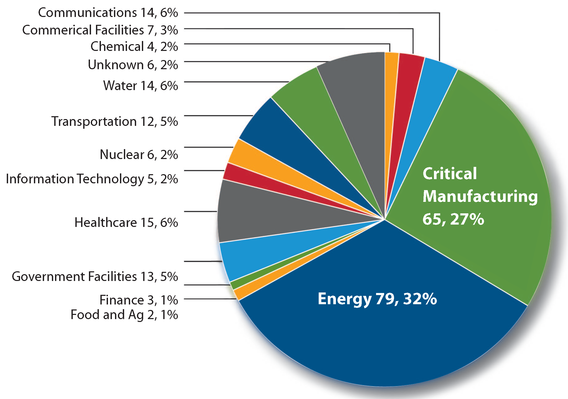
9]. ICS-CERT has tracked a large number of attacks against ICS systems (
Figure 1) and critical national infrastructure over recent years with a large portion of those being investigated, and publicised, occurring in the energy sector.
Obviously the protection of systems that operate the majority of a nation’s critical infrastructure is a primary concern for governments. The EU Cyber Security Strategy compels organisations to report CNI incidents to a competent authority and in the US an order to promote the sharing of information on incidents [
10] has been signed. The UK’s CPNI [
11], and the US DOE, advise that organisations carefully monitor their networks for signs of intrusion or attack.
Figure 1.
ICS-CERT Monitor report 2014/15 [
9].
Figure 1.
ICS-CERT Monitor report 2014/15 [
9].
Many monitoring proposals have focused on revising enterprise solutions, such as Intrusion Detection Systems (IDS), for ICS/SCADA environments [
12,
13]. These approaches are successful at identifying a limited range of attacks, but are often not capable of detecting the unique signatures of advanced persistent threats (APT) due to the specialisation of the components and attack-tools utilised. In addition their deployment in the settings of a real-time, critical system can severely impede the system operation itself through the introduction of time delays that mean the system’s control programmes are not able to respond in time to abnormal events. As a consequence the deployment of security solution in the ICS space has been hampered and in many cases even known patches for security vulnerabilities of deployed components are not rolled out, or on maintenance cycles that leave the system vulnerable for prolonged periods of time. Many of the infrastructures are required to operate 24/7/365 and there are, in many cases, no backup systems on which the effect of a patch deployment can be tested for emergent system effects. This and the often proprietary nature of the protocols used in deployed infrastructures that lead to an increased adoption cost. Finding a relatively low-cost solution that provides adequate assurance without affecting the ICS network itself is one of the driving motivations of our research.
In this paper we are considering the particular threat of semantic attacks [
14]. Semantic attacks change the behaviour of critical systems components such as PLCs in a subtle way, making it difficult for traditional IDS systems to detect. This change, however, can be leading to an overall degradation of the system that is manifesting itself in increased tolerances during production or increased wear of equipment used in the production line. A well known and widely reported case of a semantic attack was the case with Stuxnet [
2]. This type of attack might not be immediately recognised, unlike denial of service (DoS) style attacks, when systems are noticeably non-functional.
In this paper we treat the security breach within an ICS as the malicious and intentional attempt to subvert the safety of the system to cause harm to the operating organisation. This means our focus is on the functional behaviour of the system and in its current form is not intended to address more traditional security properties such as confidentiality. Our approach applies established runtime-monitoring techniques that are based on the ITL/Tempura framework [
15] and adapt them to provide an early warning system that can be deployed in an ICS/SCADA environment.
The approach offers the opportunity for real-time detection and response to unusual activities through semantic monitoring of safety and security properties. The aim of runtime verification (RTV) is the detection of violations of correctness properties [
16]. We consider a run of a system to be a finite sequence of system states. Most RTV approaches are checking correctness properties that are derived from the system’s requirements by monitoring the execution of the system. The monitor will raise an alert if the run is entering a state that violates the correctness property. This is one of the limitations of our approach, as we consider the system specification, or an uncompromised version of the ladder logic, to be available—which is not always the case as ICS and SCADA systems have typically been evolved over time and access to adequate and accurate documentation in terms of asset management and configuration management is not always maintained. However, our approach does not require complete specifications and a good starting point are safety properties that are identified in safety cases used in the certification of the deployed system.
The contribution of this paper is an approach to monitor safety properties of ICS components based on a formal and verifiable specification of the component’s behaviour. The solution is designed to be passive and is designed to be non-intrusive to the existing technology in recognition that existing ICS/SCADA systems often accommodate fragile timing constraints. Our approach addresses the cyber security challenge of ICS and SCADA through providing a low-cost and formally verifiable approach to monitor component’s functional behaviour through the deployment of monitors in the control system that verify the behaviour of e.g., PLCs in the system. The RTV monitor alerts operators to any violation of the contained specification and thus providing additional situational awareness and fault detection that could be the result of a semantic attack on the ICS infrastructure that would otherwise be difficult to detect. In comparison with IDS approaches that are based on the learning of normal system behaviours, our approach starts with the intended system behaviour specification and integrates in the configuration management activities of the systems to provide failure alerts. This is advantageous when exceptional system behaviours are considered that would in the case of IDS raise false alarms an lead to the protection mechanisms to be disabled. An example would be the trigger of safety protocols that an IDS would not consider normal behaviour. A cyber attack that is aided by physical intervention to trigger faults would lead to the execution of safety protocols which would render an IDS approach vulnerable. This paper expands significantly on earlier work [
17] in that the runtime monitor is now implemented to run on a Arduino device, making the deployment of this technology self-contained and reducing the opportunity of an attacker to mount a man-in the middle attack against the monitoring framework.
The rest of this paper is structured as follows:
Section 2 reviews related work while
Section 3 covers background material on SCADA architectures.
Section 4 then introduces our runtime monitoring approach. This includes an overview, introduction to syntax and our approach for implementation. In
Section 4.1 we provide the informal and formal semantics of PLC ladder logic constructs in ITL and its executable subset Tempura. In
Section 4.2 we provide the detailed implementation of a case study that is used to evaluate the performance and functionality of our prototype. In
Section 4.3 we present the results of our evaluation in terms of performance and discuss limitations of the Arduino implementation for RTV. Finally
Section 5 concludes and identifies avenues for potential future work.
2. Related Work
Earlier work on monitoring ICS/SCADA environments applied enterprise solutions to control system infrastructures. For example [
18] and others have created rulesets for IDS that are applicable to ICS protocols. This requires extensive vulnerability assessments of ICS protocols [
19]. This approach is useful but limited when considering semantic attacks [
14], e.g., an attack may adhere to protocol standards, but may set a gauge to a value that is not allowed by the business/industrial rules, as was the case with Stuxnet, this would not be detectable without the functional context of the system specification. Alternative approaches to IDS have been proposed, such as model-based IDS [
13,
20].
In [
16] a brief overview of runtime verification is given including a comparison with theorem proving, model checking and testing. The main aim of runtime verification is the detection of violations of correctness properties. A run of a system is a possible infinite sequence of system’s states. An execution of a system is a finite prefix of a run. In theorem proving and model checkers one considers all possible runs of a systems and in testing one considers a selected subset of all possible runs. In runtime verification however one considers executions of a system A monitor is used to check whether an execution satisfies a correctness property and the monitor is automatically generated from this correctness property.
McLaughlin
et al. [
21] proposed SABOT, a tool that automatically maps PLC logic to a provided specification to derive semantics. Similarly the ICS-Map project attempted to adapt network mapping techniques to control systems to aid the discovery of system components to feed into the automated asset discovery process. Both approaches are supplemental to our work and allow the specification of the ICS and its components to be discovered, rather than assumed. Mohan
et al. [
22] proposed S3A, an architecture deployed on an FPGA that detects malicious changes to state when execution times differ, which addresses some of the real-time challenges identified. Our approach is capable of addressing real-time properties, however, the focus is on semantic attacks against the logic of the PLCs rather than exploitation of timing behaviours.
Our work is most closely aligned with [
14] who proposed analysing the internal state of PLCs for safety and security monitoring, using existing network traffic, to identify semantic attacks. Our work differs by the choice of formal language; we propose the use of ITL and Tempura and low cost micro-controller deployment. This is advantageous, as the formal semantics can be used to simulate and analyse the formal specification and thus reason about boundary cases.
One technique of generating such monitors is by translating the correctness property into an automaton, either deterministic [
23], non-deterministic [
24,
25], with counters [
24] or alternating [
26,
27,
28]. The construction of a non-deterministic, with counters or alternating automaton for a correctness property reduces the size and speeds up the monitoring performance. The execution of the system is then fed to the automaton corresponding to the correctness property. If the automaton accepts the execution then this execution satisfies the correctness property. There are several ways of defining this acceptance condition. Via the standard final state definition one needs to consider the whole execution to determine whether the automaton accepts or not. This can be relaxed via the introduction of unconditionally accepting and unconditionally non-accepting states and constructing the complement automaton for the correctness property [
24] then in certain cases one does not need to consider the whole execution. Our approach is based on rewriting and reduction steps. The specification is rewritten into a form that specifies the current state of system and the behaviour from the next state onward. The underlying Tempura engine that was adapted to run on Arduino technology rewrites a formula in checking that the current state of the system conforms to the specification before reducing the formula to the future part, in effect advancing to the next state. Concrete details and a more theoretical treatment can be found in [
29]. This approach is shared with a number of other works that are based on rewrite systems [
29,
30,
31,
32,
33]. The correctness property is first rewritten into a normal form and the rewrite system is used to constantly rewrite the property as one checks the execution of the system. The rules in this rewrite systems are such that one part deals with what should hold now (current state) and another part with what should hold in the next state. The part what should hold now is used to check the current in the execution while the other part is used to rewrite the property.
A third technique of generating a monitor is by rewriting the correctness property into a dynamic programming algorithm [
30,
34]. It is a compiled version of the rewrite system with optimisations. The execution of the system is then fed to this algorithm.
The difference between the techniques described above and our technique is that we rewrite the execution of the system into a normal form instead of manipulating the correctness property. This technique is thus orthogonal to the techniques of generating a monitor corresponding to a correctness property.
3. Background
ICS and SCADA systems have been common in industry and manufacturing since the 1940’s [
4]. They are found in many diverse industries, such as transportation, manufacturing, chemical processing, power generation and water processing making them a key component in a countries CNI.
Historically, ICS deployments were electro-mechanical relays and switches that required direct operator control. The operator received feedback on the status of a process through analogue dials and similar methods of feedback. In the 1960’s [
4]. as technology progressed, mini-computers were used to perform the decision making and control of the systems, though these systems were very centralised, relying on mainframe computers for control and data acquisition functions.
The next development of ICS systems was in the 1990’s where micro-controllers are integrated into the control system. The use of general purpose operating systems, and open standards such as LAN protocols has allowed formerly centralised systems to become more distributed, allowing control to be located closer to the field devices [
4].
Modern SCADA architectures are composed of three segments: the corporate network segment, SCADA network segment and field devices segment [
4]. Alternative architectural frameworks describing common SCADA infrastructures are eg. found in the Purdue model [
35] or its variants [
36].
3.1. Corporate Network Segment
The Corporate network segment is a common ICT infrastructure that supports the general business functions of the organisation. In here are administrative services such as accounting, communications, email and marketing located. This segment is normally connected to the internet to perform its functions. Traditionally air-gapped from the SCADA network segment today the requirements of business to have full visibility of real-time production lead to a corrosion of these airgaps. This segment is also often connected to external providers for services such as cloud storage of hosting. As a consequence this segment shares much of the attack surface with general IT networks that are the traditional target of cyber attacks through phishing, web-vulnerabilities and generic malware infections.
3.2. SCADA Network Segment
This segment is used by operators to interact with field devices. It typically contains Human Machine Interfaces (HMI) that allow operators to control field devices such as PLCs and RTUs and maintain general control of the system through Supervisory Control and Data Acquisition (SCADA) functions. The HMIs allow operators to monitor and change values of the field devices that lead to physical changes in the system, such as the change of motor speeds. Software-based input validation is typically deployed to prevent operator errors to avoid accidental or malicious (sabotage) changes that would endanger the plant and potentially lead to the loss of human life. To acquire and store data Historian systems are used that provide an audit trail of operational data. This database may contain information from thousands of devices and needs to be capable of processing and storing these in real-time.
3.3. Field Devices
This segment is comprised of Programmable Logic Controllers (PLCs), Remote Terminal Units (RTUs) and Intelligent Electronic Devices (IEDs). PLCs are small computers that are able to automate control decisions through a control logic, commonly described in terms of Ladder logic, although other languages exists and are often proprietary to the vendor. The PLCs are fed data by RTUs that monitor and control the IEDs. The IEDs are sensors and actuators that are implemented on microprocessor devices, examples are motors and circuit-breakers. The RTUs and PLCs can control some of the ICS through the IEDs directly, e.g., by regulating valves or activating switches. The control decisions are taken on the basis of either sensor-data, or as a result of direct operator input from the control centre. The resulting control action then flows to the IED to make the change to the system. These components are physically connected by Ethernet, fibre-optic cabling, telephone lines, or wireless technologies such as microwave, satellite or radio, depending on their physical distribution.
Figure 2 shows a typical SCADA environment and presents the segments, machines and devices that have been discussed.
As ICS are today relying on general purpose operating systems, such as Windows, and common LAN and WAN technology, they are almost indistinguishable from common IT systems. One may consider that if this is the case then the issues of cyber security can be discounted, as many of the common problems that plagued IT systems over the last 20 years have been addressed by the IT industry. However, it would be a dangerous conclusion to arrive at, as the subtle differences between what could be dubbed Operational Technology and traditional IT mean that securing an OT network is not the same as securing an IT network [
38].
Figure 2.
Typical SCADA System Architecture [
37].
Figure 2.
Typical SCADA System Architecture [
37].
In this paper we are considering mainly the monitoring of Operational Technology such as field devices where the use of IDS technologies and internal protection mechanisms such as AV is not feasible due to the lack of computation power, or not well established.
4. Runtime Monitoring Interval Temporal Logic
Interval Temporal Logic (ITL) is a flexible notation for both propositional and first-order reasoning about periods of time found in descriptions of hardware and software systems [
29]. Unlike most temporal logics, ITL can handle both sequential and parallel composition and offers powerful and extensible specification and proof techniques for reasoning about properties involving safety, liveness and projected time. Timing constraints are expressible and furthermore most imperative programming constructs can be viewed as formulas in a slightly modified version of ITL. Tempura provides an executable framework for developing and experimenting with suitable ITL specifications. In addition, ITL and its mature executable subset Tempura have been extensively used to specify the properties of real-time systems where the primitive circuits can directly be represented by a set of simple temporal formulae. In addition, various researchers have applied Tempura to hardware simulation [
39] and other areas where timing is important.
4.1. Syntax and Informal Semantics
In this section we revisit the standard semantics of Interval Temporal Logic [
15] (albeit restricted to the finite case) ITL is the underlying formalism of the AnaTempura Runtime Verification Framework [
29] which uses an
executable subset of ITL called
Tempura developed by [
40,
41].
The key notion of ITL is an interval. An interval σ is considered to be a non-empty, finite sequence of states , where a state is a mapping from the set of variables to the set of values . The length |σ| is equal to n.
4.1.1. Syntax
The syntax of ITL is defined below, where μ is an integer value, v is a variable, g is a function symbol and p is a predicate symbol.
4.1.2. Informal Semantics
The informal semantics of the most interesting constructs are as follows:
: unit interval (length 1, i.e., an interval of two states).
: holds if the interval can be decomposed (“chopped”) into a prefix and suffix interval, such that
holds over the prefix and
over the suffix. Note the last state of the interval over which
holds is shared with the interval over which
holds.
f*: holds if the interval is decomposable into a finite number of intervals such that for each of them
f holds.
v: value of v in the next state when evaluated on an interval of length at least one, otherwise an arbitrary value.
v: value of v in the final state when evaluated on a finite interval, otherwise an arbitrary value.
ITL is well suited to specify sets of intervals that describe the components behaviour. In effect an ITL formula will specify the acceptable behaviour of a device in the control system. Our approach is monitoring the behaviour of these components and verify that the behaviour exhibited by the component (the current trace) satisfies its specification in form of an ITL formula. These properties can express safety properties of the system, e.g., the following formula:
would denote that
x remains constant over the interval. The formula:
would denote that the value of
x is monotonic increasing until the point at which an interrupt occurs. Subsequently the value of x remains stable as in the first example. In the above examples the formula
denotes that
f holds for all suffix intervals; the formula
denotes that the interval ends with the first occurrence of
w. The concatenation of the two specifications using ; shows the compositional nature of these specifications. For readability we introduce a number of derived constructs that are used in
Section 4.2.
4.1.3. Derived Constructs
The following lists some of the derived constructs used in the remainder of this paper. The Boolean operators ⌄ (or) and ⊃ (implication) are derived as usual.
f next f, f holds from the next state. Example: : Any interval such that the value of X in the second state is 1 and the length of that interval is at least 1.
non-empty interval, i.e., any interval of length at least one.
interval, i.e., any interval of length zero (just one state).
f sometimes f, i.e., any interval such that f holds over a suffix of that interval. Example:
: Any interval such that there exists a state in which X is not equal to 1.
always f, i.e., any interval such that f holds for all suffixes of that interval. Example:
: Any interval such that the value of X is equal to 1 in all states of that interval. final state, i.e., any interval such that f holds in the final state of that interval. Existential quantification.
holds if the length of the interval is e.
4.1.4. Formal Semantics
Let stand for the set of integer numbers, and the set of integer variables. We denote by the set of all total functions from E to F. We assume that a total function is associated with each n-ary function symbol g, and a total function is associated with each n-ary relation symbol p. Function symbols, e.g., + and −, and relation symbols, e.g., ≥ and =, have their standard meanings. In particular, the truth-values tt and ff are associated with true and false, respectively.
An interval is a finite nonempty sequence of states
, where each state
is a
value assignment which associates an integer number with each variable:
We denote by
the sets of finite intervals. For any
and an interval
σ such that
, we write
to denote the subinterval
of
σ. Given two intervals
, we write
if the intervals
σ and
are identical with the possible exception of their mappings for the variable
v,
i.e.,
and
for
. The semantics of an expression
is a function
defined inductively on the structure of expressions by
where
χ denotes a choice function which maps any nonempty set to some element in the set. The
semantics of a formula f is a function
defined inductively on the structure of formulae below, where the following abbreviation is used:
The definition of
is
ITL has got a sound and compositional proof system. Interested readers are referred to [
15,
42] for the proof system and further details about the logic. We have implemented a prototype of this system on a Arduino micro-controller that is able to recognise behaviour deviation due to fault or malicious change of the internal logic, through the rewriting of such formulae.
4.2. Approach
To validate our approach we used embedded micro-controllers (Arduino) boards with Ethernet compatibility as shown in
Figure 3. Our SCADA laboratory contains a number of popular PLCs from Siemens (Berlin, Germany) and ABB (Zurich, Switzerland). We chose the Siemens S7-1200 as it is widely used and supported (shown in
Figure 3). Siemens S7-1200 controllers use the proprietary S7 communications protocol. An existing library, Snap7 and Settimino was selected to interface with the PLCs and minimal modification was required.
Figure 3.
(a) Arudino microcontroller and (b) Siemens S7-1200 PLC.
Figure 3.
(a) Arudino microcontroller and (b) Siemens S7-1200 PLC.
To explain our approach in detail we provide first the semantic framework for specifying PLC Ladder Logic and then proceed to the concrete example of a PLC program.
4.2.1. Semantics of PLC Ladder Logic
To use Tempura to monitor control systems components such as PLC, we needed to define the semantics of their programming. The following presents the ITL/Tempura definition of a Siemens S7-1200 PLC ladder logic. Tempura is a restricted (executable) subset of ITL [
40]. In the following we will provide the definition of the Tempura constructs using ITL as they occur in the Semantics of the PLC Ladder Logic, where this is not immediately obvious.
LAD Contacts
/*   In  --| |--      */
define NO(In) = {if In=0 then 0 else 1}.
/*   In  --|/|--      */
define NC(In) = {if In=1 then 0 else 1}.
/* --| NOT |--- */
define NOT(In) = {if In = 1 then 0 else 1}.
And, Or and Xor
/*   In1    In2
   --| |----| |--  AND(In1,In2)  */
define AND(In1,In2) = {if (In1 =1 and In2=1) then 1 else 0}.
define AND_IL(In) = {if (forall i<|In| : In[i]=1) then 1 else 0}.
/*   In1
  |--| |--|-----  Or(In1,In2)
  |       |
  |  In2  |
  |--| |--| */
define OR(In1,In2) = {if (In1=0 and In2=0) then 0 else 1}.
define  OR_IL(In) = {if (forall i<|In| : In[i]=0) then 0 else 1}.
define XOR(In1,In2) = {
  if (In1=0 and In2=1) or (In1=1 and In2=0) then 1 else 0}.
define XOR_IL(In) =
  {if |In| < 2
   then { format(“Error: at least two inputs\n”) }
   else {if |In| = 2
         then { XOR(In[0],In[1]) }
         else { XOR([In[0],XOR_IL(In[1..|In|])]) } }
}.
And, Or and Xor can be applied to lists of inputs (_IL). In Tempura lists are dereferenced using the commonly used l[i] to access the ith element of the list. The length of a list is denoted by |l|. The bounded quantification forall i<|In| : f is defined as .
Output Coil
/*  Out
  --( )--  */
define  COIL(In,Out) = { Out := In }.
/*  Out
  --(/)-- */
define NCOIL(In,Out) = { Out := NOT(In) }.
The Tempura operator Out := In (unit assignment) is defined as .
Set and Reset
/*  Out
  --(S)-- */
define SET(In, Out) = { Out := if In=1 then 1 else Out}.
/*  Out
  --(R)-- */
define RESET(In, Out) = { Out := if In=1 then 0 else Out}.
Latches
/* Set-dominant and Reset-dominant bit latches */
/*    Out
   ---------
   |  RS   |
  -|R      |
   |      Q|-
  -|S1     |
   --------- */
define RS_LATCH(R,S1,Out,Q) = {
    Q is Out and
    Out := if (S1=0 and R=0) then Out
           else
            if (S1=0 and R=1) then 0
            else
             if (S1=1 and R=0) then 1
             else
              if (S1=1 and R=1) then 1
}.
/*    Out
   ---------
   |  SR   |
  -|S      |
   |      Q|-
  -|R1     |
   --------- */
define SR_LATCH(S,R1,Out,Q) = {
    Q is Out and
    Out := if (S=0 and R1=0) then Out
           else
            if (S=0 and R1=1) then 0
            else
             if (S=1 and R1=0) then 1
             else
              if (S=1 and R1=1) then 0
}.
The Tempura construct Q is Out is defined as .
Edge Instructions
/*  In
  --|P|--
    M       */
define POS_EDGE_ADDRESS(M,In) = { if M=0 and In=1 then 1 else 0}.
/*  In
  --|N|--
    M       */
define NEG_EDGE_ADDRESS(M,In) = { if M=1 and In=0 then 1 else 0}.
Edge Instructions with Coil
/*  Out
  --(P)--
    M      */
define POS_Edge_RLO(In,M,Out) = {
    M:=In and
    Out:= if M=0 and In=1 then 1 else 0
}.
/*  Out
  --(N)--
    M      */
define NEG_EDGE_RLO(In,M,Out) = {
    M:=In and
    Out:= if M=1 and In=0 then 1 else 0
}.
Triggers
/* ---------------
   |   P_TRIG    |
  -| CLK        Q|-
   ---------------
          M         */
define P_TRIG(CLK,M,Q) = {
     M:=CLK and
     Q:= if M=0 and CLK=1 then 1 else 0
}.
/* ---------------
   |   N_TRIG    |
  -| CLK        Q|-
   ---------------
          M        */
define N_TRIG(CLK,M,Q) = {
     M:=CLK and
     Q:= if M=1 and CLK=0 then 1 else 0
}.
4.2.2. Example PLC Program
This program has a single external input PB and four outputs PL0-3 that are connected to the following ladder. These were executed on a Siemens S7-1200 PLC in our experiment.
/*      PL3     PL0
    |---| |-----( )---|
    |                 |
    |   PL2     PL1   |
    |---| |-----( )---|
    |                 |
    |   PB      PL2   |
    |---| |-----( )---|
    |                 |
    |   PL1     PL3   |
    |---| |-----( )---|
    |                 |   */
define plc(PB,PL) = {
  /* let’s output the value of PB and PL in each state */
  always ( format("PB=%d, PL=%t\n",PB,PL) )  and
  { /* the first rung */
   { COIL(NO(PL[3]),PL[0]) and skip and no_ch(PB,PL[1],PL[2],PL[3]) };
    /* the second rung */
   { COIL(NO(PL[2]),PL[1]) and skip and no_ch(PB,PL[0],PL[2],PL[3]) };
    /* the third rung */
   { COIL(NO(PB),PL[2])    and skip and no_ch(PB,PL[0],PL[1],PL[3]) };
    /* the fourth rung */
   { COIL(NO(PL[1]),PL[3]) and skip and no_ch(PB,PL[0],PL[1],PL[2]) }
  }
}.
Here is a unit interval. The abbreviation no_ch(...) means that all variables in ... remain unchanged during the interval. The “chop” (;) is a crucial element of the specification and the main motivator for using ITL. Rungs need to be evaluated sequentially, which makes the compositional definition using “chop” natural.
To test our RTV approach we launched two exploits against the PLC. First we used an existing publicly available exploit that sets the PLC run mode to OFF. Tempura detects this as the PLC does not enter the next expected state in the duration of time expected. This type of exploit could be trivially detected by an existing monitoring system such as IDS and presents a proof of concept for our approach.
The second exploit is more advanced; we maliciously uploaded new program code that is slightly different to the original code, in effect changing the drill activity on a Fisher-Technik assembly line that was used to simulate our real production system. This simulates a assembly line in which a drill is used on work-products as the progress on the conveyor belt. In this case we are violating one of the safety precautions and simulate drilling even if no product is placed. This is detected by Tempura as the state transition does not match the Tempura formula that was specified for the PLC. This semantic attack might not be detected by an existing system as the signature matches normal behaviour and instead breaks operational safety rules.
4.3. Results
The monitoring technique captures a snapshot of the current state of the PLC, as shown in
Table 1. Values for Markers, Digital Inputs and Outputs, Counters and Timers are captured. Historic data is stored on an SD card for backup and offline analysis through a sliding window. This is facilitating forensic analysis after a critical breach an can provide additional information that is not normally reported to or stored by Historian databases, as it directly relates to the action taken by the controller rather than monitoring and archiving sensor data.
Table 1 shows an example of the data trace (Run) that is captured by the Arduino device and fed into the runtime-monitoring software.
Our initial prototype [
17] sent these data to a Tempura programme on an x86 Linux workstation. We implemented a modified version of Tempura to execute directly on the Arduino Yun using MIPS and the Atheros 71XX toolchain with the Arduino Yun now being able to verify properties without the need of an external toolchain. This means that the Arduino can now be deployed to sit alongside the system component it is monitoring, such as the PLC, not requiring a separate high power computing device. A remaining limitation of the current prototype is that it actively receives data from the PLC over its Profinet interface. This can be overcome with alternative passive monitoring techniques such as used in [
14]. However, our current approach is feasible as the computation times for the ladder logic in
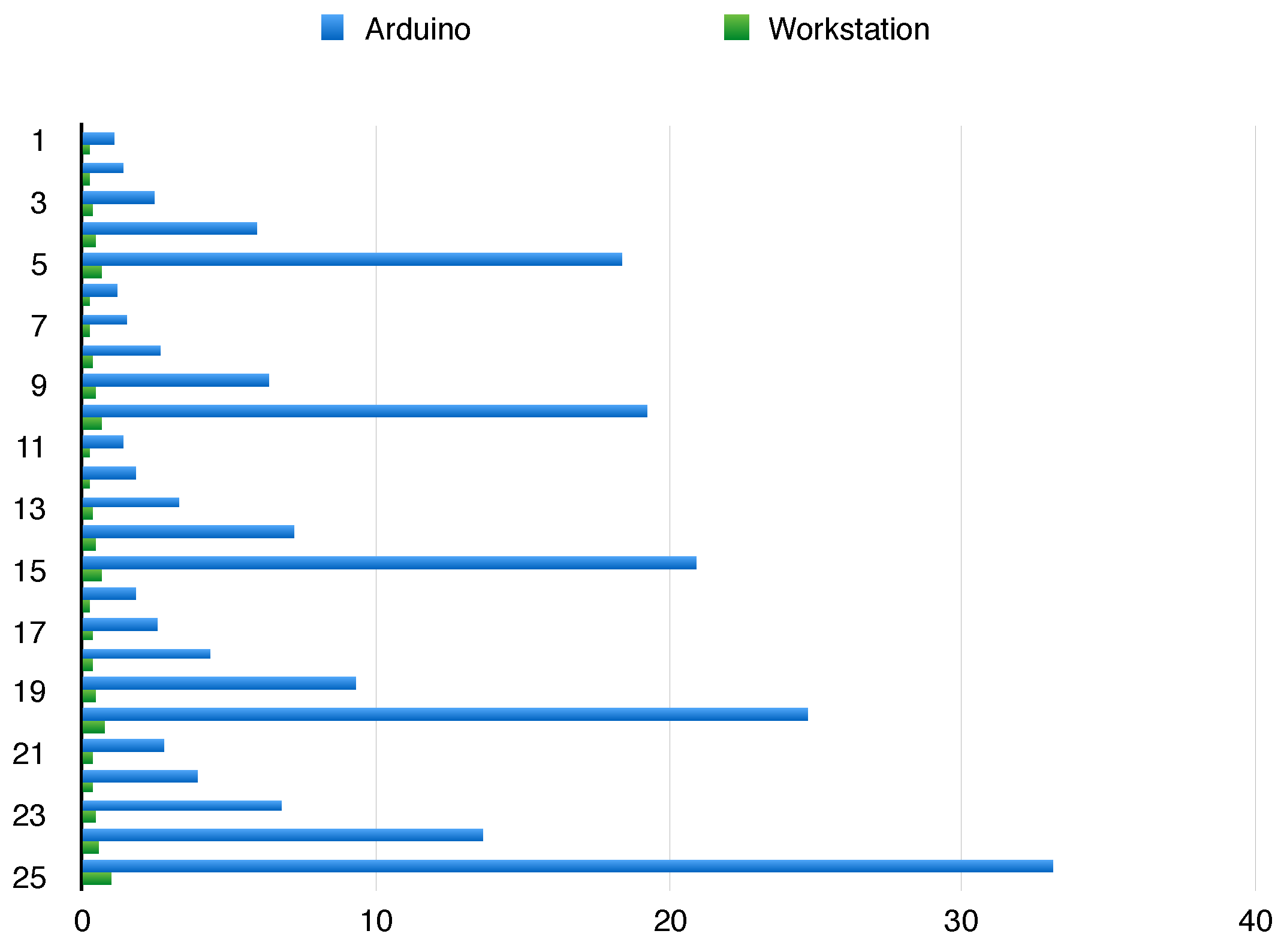
Section 4.2.2 are within the typical scan-cycle of PLCs (1–300ms). Exemplar execution times are shown in
Figure 4 where the execution of our Arduino based implementation and our previous work [
17] are compared.
Table 1.
Sensor captures PLC state transitions
Table 1.
Sensor captures PLC state transitions
| State 1 | Base State |
|---|
| MK: | 00 00 00 00 00 00 00 00 00 00 00 00 00 00 |
| DI: | 01 00 00 00 00 00 00 00 00 00 00 00 00 00 |
| DO: | 04 00 00 00 00 00 00 00 00 00 00 00 00 00 |
| CT: | 04 00 00 00 00 00 00 00 00 00 00 00 00 00 |
| TI: | 04 00 00 00 00 00 00 00 00 00 00 00 00 00 |
| State 2 | PB pushed and PL2 set |
| MK: | 00 00 00 00 00 00 00 00 00 00 00 00 00 00 |
| DI: | 01 00 00 00 00 00 00 00 00 00 00 00 00 00 |
| DO: | 06 00 00 00 00 00 00 00 00 00 00 00 00 00 |
| CT: | 0F 00 00 00 00 00 00 00 00 00 00 00 00 00 |
| TI: | 0F 00 00 00 00 00 00 00 00 00 00 00 00 00 |
| State 3 | PB pushed and PL3,2,1 set |
| MK: | 00 00 00 00 00 00 00 00 00 00 00 00 00 00 |
| DI: | 01 00 00 00 00 00 00 00 00 00 00 00 00 00 |
| DO: | 0E 00 00 00 00 00 00 00 00 00 00 00 00 00 |
| CT: | 0F 00 00 00 00 00 00 00 00 00 00 00 00 00 |
| TI: | 0F 00 00 00 00 00 00 00 00 00 00 00 00 00 |
| State 4 | PB pushed and PL3,2,1,0 set |
| MK: | 00 00 00 00 00 00 00 00 00 00 00 00 00 00 |
| DI: | 01 00 00 00 00 00 00 00 00 00 00 00 00 00 |
| DO: | 0F 00 00 00 00 00 00 00 00 00 00 00 00 00 |
| CT: | 0F 00 00 00 00 00 00 00 00 00 00 00 00 00 |
| TI: | 0F 00 00 00 00 00 00 00 00 00 00 00 00 00 |
| State 5 | PB released and PL3,1,0 set |
| MK: | 00 00 00 00 00 00 00 00 00 00 00 00 00 00 |
| DI: | 00 00 00 00 00 00 00 00 00 00 00 00 00 00 |
| DO: | 0B 00 00 00 00 00 00 00 00 00 00 00 00 00 |
| CT: | 0F 00 00 00 00 00 00 00 00 00 00 00 00 00 |
| TI: | 0F 00 00 00 00 00 00 00 00 00 00 00 00 00 |
Figure 4.
Comparison of execution times.
Figure 4.
Comparison of execution times.
In our experiment we aimed to establish the effect that the number of inputs and outputs has on a typical ladder (using AND). The resulting ladder structure is depicted in
Figure 5.
Figure 5.
Ladder logic for experiment.
Figure 5.
Ladder logic for experiment.
The experiment increases the number of inputs and outputs in exponential steps as shown in
Table 2. The initial run (1) has 8 inputs (
) and 8 outputs (
); the second run has 8 inputs and 16 outputs (
); increasing in powers of 2 until run 5 has 128 (
) outputs. Each run continues over 25 scan-cycles of the PLC to get a view of the performance behaviours over time.
Table 2.
Arduino vs. Workstation Execution times.
Table 2.
Arduino vs. Workstation Execution times.
| Run (25 cycles) | width | rungs | Arduino (in s) | Workstation (in s) | Arduino Cycle Time |
|---|
| 1 | 8 | 8 | 1.098652 | 0.284879 | 0.04394608 |
| 2 | 8 | 16 | 1.383761 | 0.289258 | 0.05535044 |
| 3 | 8 | 32 | 2.474498 | 0.321464 | 0.09897992 |
| 4 | 8 | 64 | 5.983378 | 0.411479 | 0.23933512 |
| 5 | 8 | 128 | 18.352708 | 0.652042 | 0.73410832 |
| 6 | 16 | 8 | 1.214912 | 0.288827 | 0.04859648 |
| 7 | 16 | 16 | 1.561846 | 0.292534 | 0.06247384 |
| 8 | 16 | 32 | 2.702835 | 0.320951 | 0.1081134 |
| 9 | 16 | 64 | 6.376643 | 0.418389 | 0.25506572 |
| 10 | 16 | 128 | 19.232659 | 0.652068 | 0.76930636 |
| 11 | 32 | 8 | 1.394678 | 0.287716 | 0.05578712 |
| 12 | 32 | 16 | 1.870166 | 0.302580 | 0.07480664 |
| 13 | 32 | 32 | 3.308286 | 0.345304 | 0.13233144 |
| 14 | 32 | 64 | 7.254494 | 0.439429 | 0.29017976 |
| 15 | 32 | 128 | 20.950088 | 0.695534 | 0.83800352 |
| 16 | 64 | 8 | 1.828162 | 0.300098 | 0.07312648 |
| 17 | 64 | 16 | 2.520783 | 0.320074 | 0.10083132 |
| 18 | 64 | 32 | 4.374399 | 0.379231 | 0.17497596 |
| 19 | 64 | 64 | 9.367750 | 0.491460 | 0.374710 |
| 20 | 64 | 128 | 24.755715 | 0.785922 | 0.9902286 |
| 21 | 128 | 8 | 2.755121 | 0.343993 | 0.11020484 |
| 22 | 128 | 16 | 3.954991 | 0.385808 | 0.15819964 |
| 23 | 128 | 32 | 6.752542 | 0.451242 | 0.27010168 |
| 24 | 128 | 64 | 13.664713 | 0.592664 | 0.54658852 |
| 25 | 128 | 128 | 33.034423 | 0.957798 | 1.32137692 |
Run 6 then continues to increase the number of inputs to cycles through the number of outputs analogous to the first sequence (run 1-5), but now with the number of inputs remaining at 16 (). This scheme continues until the last run (25) where the ladder contains 128 inputs and 128 outputs ().
This scheme was chosen to identify the performance behaviour corresponding to the size of the ladder in terms of width and number of rungs.
Figure 4 clearly shows some peaks for the Arduino, namely in runs (5,10,15,20,25) during which the Tempura engine performs an internal garbage collection. This is the effect that can be seen with the default Tempura compilation settings. The current version of Tempura allows to restrict the running of the garbage collector to specific times to better control this effect; an alternative is to analyse the memory usage of the concrete ladder beforehand and adjust the memory allocation during compile-time.
Table 2 shows the concrete execution times of this experiment including the ladder width and number of rungs. Whilst the Arduino is performing significantly (Factor 10) worse than the original workstation solution [
17], we consider a cycle time of 300 ms or less to mean that the solution is applicable. The advantage of the native arduino approach is the reduced cost and improved deployment factor that was one of our main aims of investigation. This means that this is only limiting the application where ladders are exceeding 64 inputs and 64 outputs which are not often encountered.
From a functional point of view the results of both the Arduino and the Linux implementation are identical in all test cases we have run (including other examples from the current Tempura distribution, such as the large scale EP3 example). This means that when Tempura notices that the output does not match the formal description, an alert is raised and an audible warning sound emits from the Arduino micro-controller. In a real deployment this of course could be enhanced by sending a text message to a Factory Manager or alerting the security operations centre (SOC) for the organisation.
This approach means that any update or new deployment of ICS components requires to modify the specification of the attached runtime monitoring device. This requires the integration of the mechanism into existing configuration management processes of the plant. The applications of this technology are therefore wider than just the monitoring of safety properties for enhancing the situational awareness and detectability of semantic level cyber attacks. The runtime monitors also play a vital role in the management of the evolution of the system in flagging up adhoc changes to programme code that do not satisfy previously defined component specification. This is a valuable addition to pre-deployment tests and provides additional assurances on the functioning of the system.
Whilst the approach does not prevent cyber attacks, it is a critical component of any incident response support to identify current stages and compromised nodes of a system under attack. The presented run-time monitoring system is capable of providing this situational awareness. An obvious risk is that both the Arduino and the system are compromised by an high capability adversary. Whilst this cannot be completely ruled out, we seeing the deployment of the Arduino based monitors in isolation of the network (ie, the arduino is not accepting input from the control network) through separation of networking channels. Whilst this does not offer complete protection, it significantly raises the required resources to launch an undetected semantic attack against a ICS component.
5. Conclusions
We presented a run-time monitoring framework that is deployed on Arduino Yun devices and based on a formal rewriting mechanisms that establishes whether the behaviour of a ICS component complies with a given specification. This specification is build upon the safety case for the system and distinguishes itself by the compositional nature that allows to reason about the parts of the monitoring specification and infer properties of the whole. We have provided the motivation and implementation of the existing Tempura framework based on Arduino technology and developed a prototype that is demonstrating the feasibility of the approach. Our experiments have demonstrated that this approach to safety and security monitoring in ICS environments is feasible. However, this approach is by no means a silver-bullet solution and should be incorporated as part of a multilayer security architecture and should be seen as an additional capability and safeguard to protect the system against semantic attacks. To some extend this technology also makes insider attacks more difficult to achieve, as a remote access to an engineering workstation is no longer sufficient to update the control logic as part of a semantic attack. The attacker in addition must gain access to the monitor and replace the monitor in conjunction with the code update. As these are separate channels and the monitor requires physical access or access to a different network this is significantly harder to achieve without raising an alarm through the monitor when compared to systems that do not employ run-time monitors.
Future work should validate the approach alongside other techniques and assess the added resilience to semantic attacks and measure the security benefit of deploying such a solution. This is currently not feasible due to the lack of adequate metrics to measure the effectiveness in a realistic setting, which we are actively investigating. Other work we are pursuing is the distributed monitoring of these systems and allowing monitors to share their activity, with the view of including sleep-wake cycles to further reduce the surface for an attacker to identify and side-step the monitoring technology.
The approach presented is a step towards the more security aware management of CNI and their ICS. Whilst our technology is targeting the popular Siemens S7-1200 series of PLC, the approach is clearly transferable to other Vendor and System types. The monitoring devices used in our approach are low cost, simple to configure, deploy and monitor, they could be a disruptive technology to monitor safety and security properties in ICS environments.


