1. Introduction
Smart homes are one of the new trends for integrating technology in people’s daily life. In general, many household devices employ electronics that are in standby mode most of the time. The average standby power consumption of individual electrical devices in homes is around 60 W–110 W per home, which is an average of 10% of the total house power consumption [
1]. However, recent studies have shown that up to 77% of energy can be saved if the electronic device is turned off completely instead of switched to the standby mode [
2]. Standby mode is defined as the minimum consumption power of a device, which means that the electronics are still active at the lowest possible operating power. It would be a better choice to completely shut down the devices by unplugging them manually from the electricity. However, each time we need to operate a device, we need to plug it in again, and this tiring process will sooner or later result in leaving the devices in the normal standby mode. Therefore, controlling the process automatically using a remote device could be the optimal solution.
Smartphones are considered a rich environment that contain several communication mediums, such as WiFi and Bluetooth. A smartphone is a device that is nicely suited as a remote control, and many users already possess one. The first option is to consider the integrated WiFi transceiver to establish a connection to an access point in the network. At the receiver side, integrated WiFi can switch the device to react to any command sent by the smartphone. However, using WiFi results in an increased energy consumption, since the WiFi chip has to be continuously connected to the network to receive the commands transmitted from the smartphone. Bluetooth Low Energy (BLE) is considered an alternative method to operate and control low power devices. A performance analysis of BLE is presented in [
3]. BLE can operate from days to several years depending on the Bluetooth activity and the required time for its active operation. However, most smartphones are not equipped with a BLE chip.
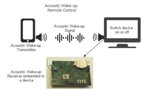
Therefore, we consider an unconventional method to wake up the receiver that is attached to a device in order to power it on or off. This method does not need any infrastructure, like an access point similar to WiFi, and it is based on the acoustic wave signals generated by the smartphone, where these acoustic waves form the wake-up signal are required to wake-up the electronic device. The concept of a wake-up receiver on a sensor node is not new; however, most of the approaches use radio frequencies (RF) for the wake-up signal [
4,
5,
6,
7,
8]. Using different approaches from RF to wake up the nodes is somehow uncommon. Furthermore, it is possible to design an optical wake-up receiver similar to [
9] that achieves a low power consumption of 695 pW.
An implementation for a surveillance sensor network using acoustic signals is considered in [
10]. The designed wake-up receiver focuses on a low power comparator integrated with a micro-electromechanical system (MEMS) microphone, where the performance of the system depends on the signal acquisition. The system consumes around 300 μW. A thorough implementation of an ultrasound wake-up receiver consuming 4 μW of current and working at 40 kHz is presented in [
11]. It uses off-the-shelf ultrasonic transducers, where a wake-up distance up to 8.6 m is achieved. Another paper presenting an ultrasonic wake-up receiver with less than 1 μW of energy operating at 40 kHz for wireless sensor networks can be found in [
12]. Bogliolo
et al. [
13] discussed a combination of an ultrasonic wake-up module that works on a frequency of 40 kHz with sustainable energy harvesting to power up the receivers. In [
14], an algorithm is presented for sensor nodes’ localization using microphones. In addition, wake-up receivers are used for localization in emergency cases [
15]. The aim of integrating wake-up receivers in sensor nodes is to reduce the power consumption by operating on low power modes. An ultrasound wake-up receiver is presented in [
16], where a wake-up signal is transmitted to the receiver when the mobile device moves into the receiver’s range.
We present an approach that has the possibility of including a 16-bit address coding in the wake-up signal, which enables selective sensor nodes to wake-up from sleep. Furthermore, the wake-up signal can be transmitted using commercial smartphones. We implemented this approach using only off-the-shelf components. In our previous work [
17], we considered an approach of acoustic wake-up receivers without considering any filter for noise cancellation and signal amplification, which resulted in a limited functionality, where a wake-up distance up to 5 m is achieved.
2. Acoustic Wake-Up Receiver Design
In this work, our current acoustic wake-up receiver is powered by a battery for measurement reasons. The receiver has to be integrated in home appliances; thus, the design considers powering the receiver through the 230 V AC without using any battery. Therefore, our focus in this work is to develop a proof of concept of the wake-up receiver.
The design of the acoustic wake-up receiver is inspired from the work presented in [
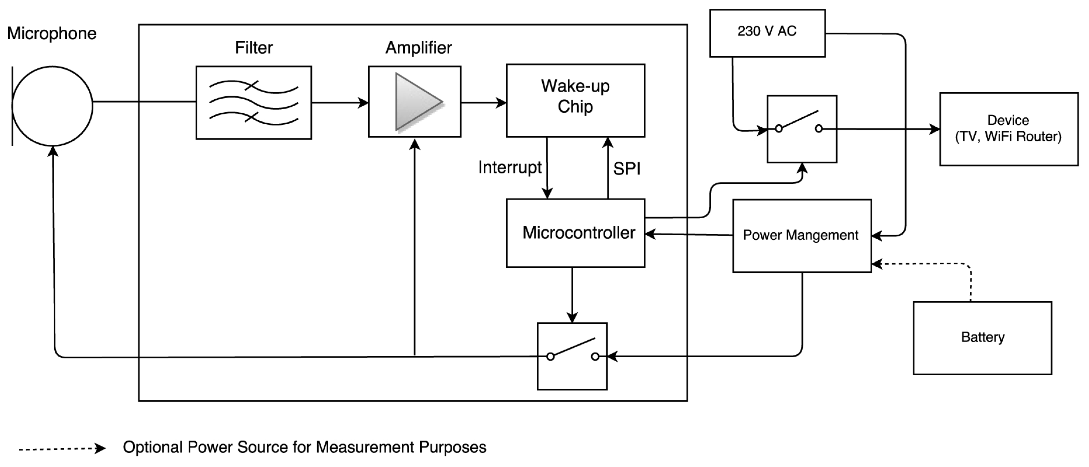
7]. The circuit contains some additional components, such as a microphone and a sound filter, to adjust to the functionality of the receiver. The design of the receiver can be seen in the block diagram in
Figure 1. The core component of the receiver consists of a low power microcontroller. It consumes a current of 0.1 μA in low power operation mode. The microcontroller is connected to a wake-up chip AS3933 [
18] that is responsible for detecting wake-up signals. The wake-up chip can react to a frequency in the range of 16–150 kHz, and it has a current consumption of 2.8 μA in deep sleep. In addition, the microcontroller communicates with the wake-up chip through a serial peripheral interface bus (SPI) in order to assign a specific wake-up address.
The microcontroller uses a duty cycle approach to switch the relay on and off to power the amplifier and the microphone. In an active period, the microphone samples audio signals and routes these signals after filtering them through the amplifier to the wake-up chip. Upon detecting a wake-up signal, the wake-up chip activates the microcontroller, which in turn switches the relay on or off to power the device, as in
Figure 1.
Figure 1.
Schematic block diagram of the acoustic wake-up receiver powering a device.
Figure 1.
Schematic block diagram of the acoustic wake-up receiver powering a device.
2.1. MEMS-Microphones
The first part in the signal chain of our receiver is a microphone, which converts the acoustic signals to electrical signals. The sensitivity for detecting the acoustic signals is very important for the reliability of the receiver. In a previous work [
19], the sensitivity as a function of frequency is measured. Four electret microphones from the manufacturers Kingstate and Ekulit and a MEMS microphone from Knowles Acoustics are used. The measurement of the frequency responses between the different types of microphones is seen in
Figure 2. In general, the frequency responses of the electret microphones have a descending trend. The MEMS microphone shows a stability, and a peak in its frequency response appears around 20 kHz. Thus, the use of the MEMS microphone is preferred for better detecting of the signals used in our receivers.
The efficiency of the MEMS microphone is measured [
20] to see in which direction and at what angles would be suitable for placing the microphone. In this measurement, 10 receivers are used. A smartphone is used to transmit 630 acoustic signals to test the reception of the receivers. We have seen that the opening of the angles depends mainly on the direction of the microphones and the detection threshold of the receiver. When the smartphone is placed in the direction of the receiver toward the microphone, a higher signal detection is achieved. When the smartphone is placed toward the backside of the receivers, the detection rate of the signals decreases. We notice that the detection threshold of the microphones achieves higher results when the smartphone is located in an angle range of 180° in front of the receivers.
Figure 2.
Frequency response of electret and MEMS microphones in the range from 500 Hz–25 kHz (adapted from Hoppe [
19], with permission from © 2012 University of Freiburg).
Figure 2.
Frequency response of electret and MEMS microphones in the range from 500 Hz–25 kHz (adapted from Hoppe [
19], with permission from © 2012 University of Freiburg).
2.2. Bandpass Filter
A passive bandpass filter is directly connected to the microphone’s output. It is considered at the receiver to increase the wake-up distance and to minimize the noise. The purpose of this filter is to lower the noise as much as possible before the first amplification stage. Initially, we have simulated several circuits that include high pass, low pass and bandpass filters to achieve a possible upper and a lower cut-off frequency of 1 kHz–20 kHz. Since most of the simulated filter circuit models require up to 63 mH inductance, we chose this since the induction is not available at all values. In addition, a special induction costs a great deal. A higher induction value needs more space in the circuit, as well. Therefore, we selected a value that considers the requirements of availability, cost and space. An LCfilter and an LC half-section filter are selected for filtering the signals. In order to avoid long interconnection, the filter is placed close to the microphone output, as seen in
Figure 3. Therefore, we minimize the noise interference before the amplifier stages. The microphones have a selective reception behavior, which works as an additional filter to the LC filter. Since no improvement in the wake-up distance can be achieved by including a secondary LC filter, we assume that one LC filter and the filtering effect of the microphone are sufficient. Thus, an increase in the signal-to-noise ratio (SNR) will increase the wake-up distance, since the maximum reachable wake-up range depends on the amplitude of the signal.
Figure 3.
A prototype of a wake-up receiver board.
Figure 3.
A prototype of a wake-up receiver board.
2.3. Amplifiers
Larger wake-up distances can be achieved by increasing the amplification of the signals. The current layout contains two amplification stages. However, only an amplification of a factor of 400 can be achieved, because the low power operational amplifier (MIC861 [
21]) has a gain-bandwidth of 400 kHz. The acoustic signal works at 20 kHz; it is only possible to achieve a maximum amplification factor of 20 per step. The amplification of the signal makes it easier for the wake-up chip to detect the signal. A complete prototype of the wake-up receiver can be seen in
Figure 3.
3. Wake-Up Signal Transmitter
Smartphones’ development has increased in the past several years to include several technologies, such as WiFi and Bluetooth, and they even could function as a complete audio system. We can use these technologies as a remote control to generate wake-up signals. However, most of the WiFi and Bluetooth chipsets in smartphones have a physical and a data link layer integrated in the hardware. It would be very difficult to manipulate the standard protocol to generate customized radio signals, which are required to wake-up the receivers. On the contrary, generating customizable audio signals can be achieved, since there is no protocol restriction and constraints on the sound. Furthermore, the programming of custom audio wave forms is quiet easy using an application programming interface (API) within the operating system of the smartphones. In addition, the power consumption of a receiver containing a WiFi chip is higher than a receiver that contains a microphone. One of the major concerns for an acoustic wake-up receiver is at what signal can the receiver work with minimal noise interference for detecting a valid wake-up signal.
3.1. Audio Frequencies
It is commonly known that the range of human hearing is between 20 Hz and 20 kHz, and it is best at frequencies where most of speech takes place, which is around 0.5–6 kHz. The ability to hear is reduced when we move out of these frequency ranges. The hearing threshold of humans increases at high frequencies [
22]. The absolute hearing threshold defines the minimum sound pressure level, which a pure tone needs to have, in order to be recognizable by human beings. Usually, the pressure levels are plotted as a function of frequency. The audibility of a sound signal depends on its frequency, its sound pressure and the individual properties of hearing [
23,
24]. The sound pressure of a smartphone depends on the distance to the smartphone and on the frequency response of the speaker. Hoppe
et al. [
25] states that an 18-kHz sound sent out by a commercial off-the-shelf smartphone can be heard by 0.13% of people at a distance of 5 m. Higher frequencies than 18 kHz cannot be heard by humans, even if the sound is generated from shorter distances.
In order to choose the right operating frequency to generate the wake-up signal, the speaker of several smartphones is characterized in the aspect of normalized amplitude
vs. frequency [
19]. The results can be seen in
Figure 4. We have seen that the the signals descend after the 6-kHz frequency, and a rise in the amplitude of the signals is found around 16 kHz, independent of the smartphone type. However, a 16-kHz frequency is found in the human hearing range. Transmitting the acoustic wake-up signals at this frequency will generate a noise that might affect human hearing. Therefore, we prefer to use a frequency that, on the one hand, still delivers a good amplitude in the smartphone speaker, but, on the other hand, that cannot be heard by humans. In addition, higher frequencies are less susceptible to environmental noise, similar to lower frequencies. Therefore, we chose 20 kHz to be the operating frequency of our wake-up signal.
Figure 4.
Normalized amplitude in dB
vs. frequency for a sinus tone with different speakers of smartphones(adapted from Hoppe [
19], with permission from © 2012 University of Freiburg).
Figure 4.
Normalized amplitude in dB
vs. frequency for a sinus tone with different speakers of smartphones(adapted from Hoppe [
19], with permission from © 2012 University of Freiburg).
3.2. Acoustic Wake-Up Signal
The generated wake-up signal has a specific pattern in order to be detected by the wake-up chip similar to the RF wake-up signals from the work presented in [
7], where amplitude shift keying is used to code the address. The acoustic wake-up signal operates at a frequency of 20 kHz, and the signal has a length of 27 ms. The acoustic wake-up signal can be seen in
Figure 5. It consists of three different parts: the first part is a carrier burst that is generated within 4.5 ms; the second part is a preamble that consists of the binary number 10101010, where a one bit is transmitted over 18 periods at a frequency of 20 kHz; the last part is a coded 16-bit address, and in
Figure 5, the address is represented by the hexadecimal number (0x6655). Addressable wake-up receivers have the advantage to react only when a matched address is detected. Due to this, several wake-up receivers can be installed within a house to control the devices separately as required.
Figure 5.
Acoustic wake-up signal.
Figure 5.
Acoustic wake-up signal.
The optimization of the wake-up signal is necessary for the operation of the receiver. The acoustic wake-up signal is generated through a burst followed by several on/off phases. The hard switching, between the on and off phases of the amplifier, generates a sine-phase and Dirac pulses at the output of the amplifier, which results in generating unwanted frequency parts. These are clearly audible through the loudspeaker and considered noise and beeping that affect the signal; thus, they are undesirable. Therefore, we optimized the generated signal in the smartphone by applying a bandpass filter, which normalizes the signal to 0 dB to avoid any noise that might result from increasing the smartphone volume to the highest level.
Figure 6 shows a section of the wake-up signal, where the upper part of the figure represents an unoptimized section of the signal, whereas the lower part is considered after optimization. Eventually, the optimized acoustic signal is not audible to humans.
Figure 6.
The upper part represents a section of an unoptimized acoustic wake-up signal. By applying a bandpass filter, an optimized acoustic wake-up signal will be generated similar to the lower part.
Figure 6.
The upper part represents a section of an unoptimized acoustic wake-up signal. By applying a bandpass filter, an optimized acoustic wake-up signal will be generated similar to the lower part.
In addition, we optimized the transmission process of the signal in the audio speaker of the smartphone. Before and after transmitting the wake-up signal, we inserted a pause period of 10 ms to avoid any noise that can be generated from operating the smartphone. The amplifier and speakers are therefore not forced immediately to operate at a frequency of 20 kHz after giving the command in the smartphone, which will help eliminate any possible noise. The signal can be played continuously within the smartphone to ensure reliability, in which a wake-up signal is correctly received by the intended wake-up receiver.
5. Conclusions
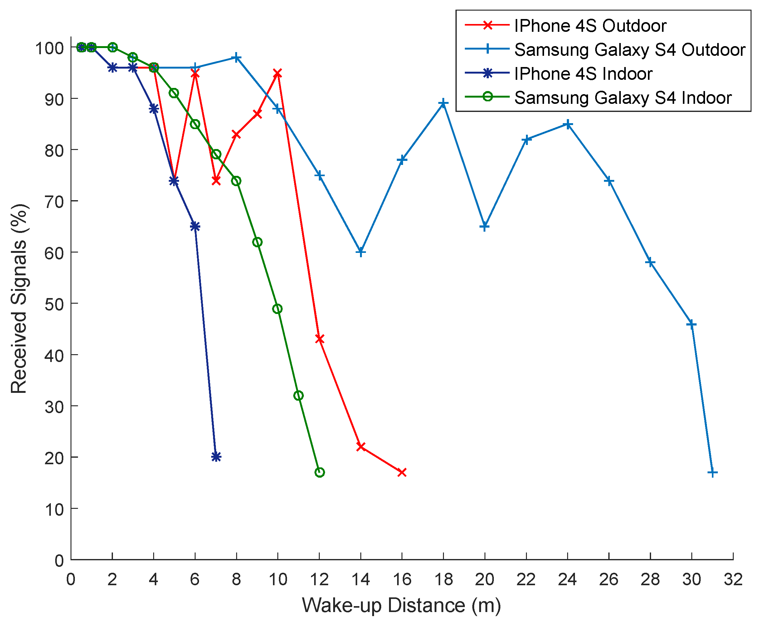
In this work, we presented a 16-bit addressable acoustic wake-up receiver, which can be used to operate home devices by powering them on and off from the main power. In this process, we power off the devices when they are not in use in order to reduce the power wasted from the continuous operation in standby mode. The receiver consists of off-the-shelf components, such as a MEMS microphone that is used to transform acoustic waves into electric voltages. In addition, the wake-up receiver includes a filter and amplifiers to reduce the noise and amplify the signals for a better detection. A duty cycle approach is used and controlled by the microcontroller. In an active phase, the MEMS microphone is powered on to receive acoustic signals. A wake-up chip detects a signal with a valid address at a frequency of 20 kHz and triggers the receiver from sleep to active mode to turn on and off home appliances upon detecting the signals. In the active phase, a receiver needs 140 μA, whereas the receiver needs 15 μA in sleep phase. The setup enables a person that possesses a smartphone to wake-up the receivers in the surroundings. A wake-up distance of 30 m is achieved outdoors, whereas a 12-m wake-up distance is reached indoors.


 ,
, 


