1. Introduction
Robotics networks have gained a lot of attention in the last decade due to the major technological advances that have widened the scope of their applications. A robot can be equipped with sensors, which enable such a network type to combine the advantages of its mobility and actuation features with the wireless sensor network capabilities. In harsh environments where human intervention is not possible, robots can be used for monitoring specific phenomena, reporting data to a base-station and taking action as deemed feasible and appropriate. Robot deployment can be done manually, by placing each node in a pre-determined position in an area of interest such that some desired coverage and connectivity properties are ensured [
1,
2]. Alternatively, robots may dynamically adjust their positions by self-spreading such that the covered area is maximized while maintaining the inter-robot connectivity [
3,
4,
5,
6,
7,
8]. The reactive nature of robots and the applications in which a robotics network is effective makes the deterministic placement impractical and adaptive self-deployment of robots more appropriate. Consequently, the need arises for a distributed method that enables the robots to be self-deployed and self-organized to accomplish a certain task. Virtual force-based [
3] deployment is one of the most commonly used distributed algorithms.
1.1. Virtual Force Approach (VF)
One of the most popular approaches for multi-robot deployment is virtual force. In this approach, there are three kinds of objects: robots, obstacles and preferential areas. All of them exert a different kind of force; either an attractive force or a repulsive force. Robots exert repulsive force and attractive force toward each other depending on the Euclidian distance between them. Obstacles exert repulsive force and preferential areas exert an attractive force on robots. In this approach, we consider the following assumptions. First, each robot has a sensing range and a communication range . Within the sensing range, the robot can detect local environments’ conditions or implement a certain task. Moreover, a robot can communicate with other robots within its communication range . We assume a circular radio coverage and circular sensing coverage. Second, the positions of all the robots are known and can be acquired. Third, all the robots can move according to the calculated results of the algorithm. Fourth, the communication range is greater than the sensing range.
1.2. Robots Movement of VF
In virtual force model, obstacles are assumed to exert repulsive (negative) forces on a robot. However, areas of preferential coverage exert attractive (positive) forces on a robot. Let
be the total (attractive) force on robot
due to preferential coverage areas, and let
be the total (repulsive) force on robot
due to obstacles. The total force
on
can now be expressed as in Equation (1).
where
is the attractive force,
is the repulsive force, and
is the distance between robot
i and robot
j,
is the distance threshold between any two nodes which control how close will be the nodes from each other, and
is the angle between node
i and node
j. The main objective of this work is to investigate how the variation of
and
affect the behavior of VF on multi-robot deployment under different scenarios.
1.3. Problem Statement
Virtual force has been proposed in [
3] to be used for mobile sensor self-deployment. However, the setting of its parameters, specifically the attractive force
and the repulsive force
has neither been discussed nor specified clearly; researchers have just mentioned that the attractive force should be much smaller than the repulsive force. Therefore, in this paper, the goal is to formulate those two factors to be a function of system parameters such as the number of robots and communication threshold. Moreover, considering the level of remaining energy in each robot is another important factor to be considered, in order to maximize the lifetime of the network. Some robots may start to deplete their energy earlier than other robots, so the possibility of these robots shutting down is very high and could cause a disruption to the robotics network. So, in this work, we present an energy aware virtual force that considers the heterogeneous level of energy among robots such that the ones with a low level of energy will be able to switch to a power saving mode and consequently maintain their energy level when possible.
The remainder of the paper is organized as follows.
Section 2 presents the related works. Then, in
Section 3, we describe the proposed approach for calibrating the virtual force parameters as well as the energy-aware virtual force approach. After that, in
Section 4, we present and discuss the simulation experiments’ results under different scenarios. The challenges and open issues are discussed in
Section 5. The details of the real experiment are presented in
Section 6. Finally,
Section 7 concludes the paper.
2. Literature Review
The virtual force algorithm (VFA) has been used widely to achieve uniform distribution of robots. The following summary presents how virtual force has been used for sensor deployment and the various amendments to it. The idea of using potential field for robot deployment was first investigated in [
9]. In the robotics field, each robot behaves as a ‘‘source of force’’ for all other robots. This force can be either positive or negative. If two robots are placed too close to each other, the ‘‘closeness’’ being measured by a pre-determined threshold, they exert negative forces on each other. This ensures that the robots are not overly clustered, leading to poor coverage in the other parts of the robotics network. On the other hand, if a pair of robots is too far apart from each, they exert positive forces on each other. In [
3], the idea of virtual force was, for the first time, used to improve the coverage after a random deployment of mobile sensors. They consider a binary detection model in which a target is detected (not detected) with complete certainty by the sensor if a target is inside (outside) its circle. After the initial random deployment, all sensor nodes are able to communicate with the cluster head. The cluster head is responsible for executing the virtual force algorithm and managing the one-time movement of sensors to the desired locations. The obstacles are considered in this work and modeled as a repulsive force. This work considers a uniform distribution of the mobile sensor. It is centralized in terms of virtual force calculation which is a single point of failure. It did not consider the heterogeneity of the mobile sensors’ energy level. Wand et al. [
10] added particle swarm optimization (PSO) to a virtual force approach. In the process of self-organized deployment, the nodes do not really move, but a cluster-head node calculates the virtual path first, and then guides cluster-in nodes to migrate once, in order to save energy. Only a uniform distribution of the mobile sensors is considered in this work and no guidelines on how to choose the virtual force parameters has been suggested. Chen et al. [
11] considered a probabilistic detection model. In reality, sensor detections are imprecise; hence, the coverage of a target point by a sensor needs to be expressed in probabilistic terms. This work considers the difference of heterogeneous sensor nodes’ sensing detection radius. They propose a “diversity degree” to compute the distance threshold between nodes in a heterogeneous network. It considers both obstacles and preferential areas. The obstacles exert a repulsive force based on a rank given to each obstacle, while the preferential areas and target points exert an attractive force based also on a rank given to each preferential point. These processes depend on a cluster head to perform all related calculations needed for robot deployment.
In order to limit the number of neighboring robots involved in virtual force computation, authors in [
12] suggest the use of Delaunay triangulation to do so. Robots will only be effected by the attractive force and the repulsive force of the nodes that are directly connected to it in the constructed Delaunay triangulation. This approach requires a lot of computation: each node is required to build a Delaunay diagram for every iteration of virtual force computations. Garetto et al. [
13] proposed a distributed sensor relocation scheme based on virtual forces, adding the restriction that there are at most only six nodes that can exert forces on the current node. This work handled the problem that arises when nodes have a high communication range by using the six nodes restrictions. In our work, we handled such problems during the formulation of the virtual force parameters.
Ying et al. use virtual force for post-deployment to improve the coverage in wireless sensor networks. They assume that static sensor nodes are initially deployed in the monitoring environment randomly, and the nodes communicate with each other to detect the coverage holes [
14]. The mobile nodes will be used for increasing the coverage. Assuming that coverage holes generate an attractive field on mobile nodes, the mobile nodes compute the virtual force for many rounds until there is no force toward the mobile node or the maximum number of rounds is reached, so the mobile nodes stay where they stop at the last round. If a force is exerted toward a mobile robot from multiple directions it will cause the robots to oscillate and trigger a lot of unnecessary movements.
The work in [
15] aims to overcome the problem of zigzag movement of sensors. Initially, sensors compute the total virtual force and move based on it; however, in some cases, the sensor may move in a zigzag manner before it reaches the final destination. Therefore, in this work, they propose a prediction mechanism where a sensor can predict its position after multiple steps and therefore moves directly to the final position. Instead of moving iteratively, sensors calculate their target position based on an iterative algorithm, move logically, and exchange new logical locations with their new logical neighbors. The actual movement only occurs when sensors determine their final locations. In this approach, all sensors need to be in the range of each other to be able to exchange their logical position and compute the next supposed position or require a network-wide broadcast of messages, which will cause the broadcast storm problem. In [
16], they propose a prediction approach for virtual force implementation. Each robot is supposed to predict its position after two or more steps in order to avoid zigzag movement and speed up the deployment process. Error is limited in [
15] by making it only a two-step prediction. The main problems with [
15] and [
16] are that: first, the network will behave poorly in case of network partitions. Each partition will predict the position of its robots without knowledge of positions of others; second, this mechanism requires a network-wide broadcast, which causes a high communication overhead. Work in [
17] adds a constraint on when a robot is allowed to move. It considers only one robot moving at a time. It assumes that, in the case where all robots relocate themselves at the same moment, some robots may move needlessly. This is because none of the robots makes their movement decision based on the most updated robots’ location information in the neighborhood. So, to solve this problem, they suggest using randomized backoff delay to allow only one robot to move at a time. This approach requires synchronization using global communication to determine the required time for each iteration of the algorithm.
Work in [
18] considers the boundary effect on virtual force calculation. The sensor is limited in its movement to the boundary of the region of interest. It also limits the number of robots that can participate in virtual force calculation by introducing a communication threshold. Robots that are far from each other and beyond the communication threshold will not effect each other, although there are actually communicating with each other. In [
19], the authors use virtual force to perform zone of interest (ZoI) coverage. They compare it with particle swarm optimization and found that virtual force is better in terms of coverage but consumes more energy. Works in [
7,
8] consider the use virtual force to achieve purposeful deployment. The area of the deployment has fixed sensors and each one has a need for a specific number of mobile sensors. The need of each fixed sensor is factored in virtual force computation in order to speed the deployment process and satisfy the demand of each fixed sensor.
As we see from the discussion above, the virtual force approach has been used in many applications. However, providing a universal setting for its parameters, specifically the attractive force and repulsive force is missing or not considered carefully. More importantly, none of these previous works has considered a real implementation for such deployment. Therefore, our aim is to fill this gap and try to provide a formulation for these factors to meet the demand of different applications. Moreover, we validate our proposed solution on real robots to demonstrate some practical results.
3. The Proposed Guidelines
In order to effectively achieve the required deployment, we investigate how to set the attractive force and repulsive force for a different number of robots with different parameters. In addition, the proposed virtual force introduces how to limit the step size that a robot can move in each round to avoid oscillation (i.e., a phenomenon appears when a robot or robots near to reach the final stage in the deployment scenario). Then, we introduce an energy aware implementation of virtual force. We consider a scenario where robots have a different level of energy and the goal is to balance energy consumption among all robots to maximize the network lifetime.
3.1. Attractive Force
In the virtual force computation, if robots are far from each other by a distance threshold, which is determined specific to system requirements, the robots are supposed to attract each other. Attracting other robots requires that the value of is set properly. If the value of is high, it will cause the robots to move a longer distance than needed and become very close to each other, which will trigger a repulsive force and then an attractive force, and so on. Consequently, the robots will not stabilize and the network convergence would be difficult to attain.
If the number of robots is high, the attractive force should be reduced such that each robot avoids attracting a large number of robots to its vicinity
. For example, in
Figure 1A, when the number of robots is high (
N = 50), setting the attractive force to be high (i.e.,
=1) caused the robots to remain close to each other, although their repulsive force is set properly. Additionally, setting the attractive force to be arbitrarily smaller compared to the repulsive force did not give the expected result, as shown in
Figure 1C.
Furthermore, if the communication range is high, this means that the robot forces (i.e., attractive and repulsive) will affect a large number of robots. In this case, it is better to tune the attractive force to be inversely proportional to the communication threshold
. In
Figure 1B, when the communication range is high (i.e.,
>
), it yields a nonuniform distribution of the robots. So, for a high number of robots, the best setting is shown in
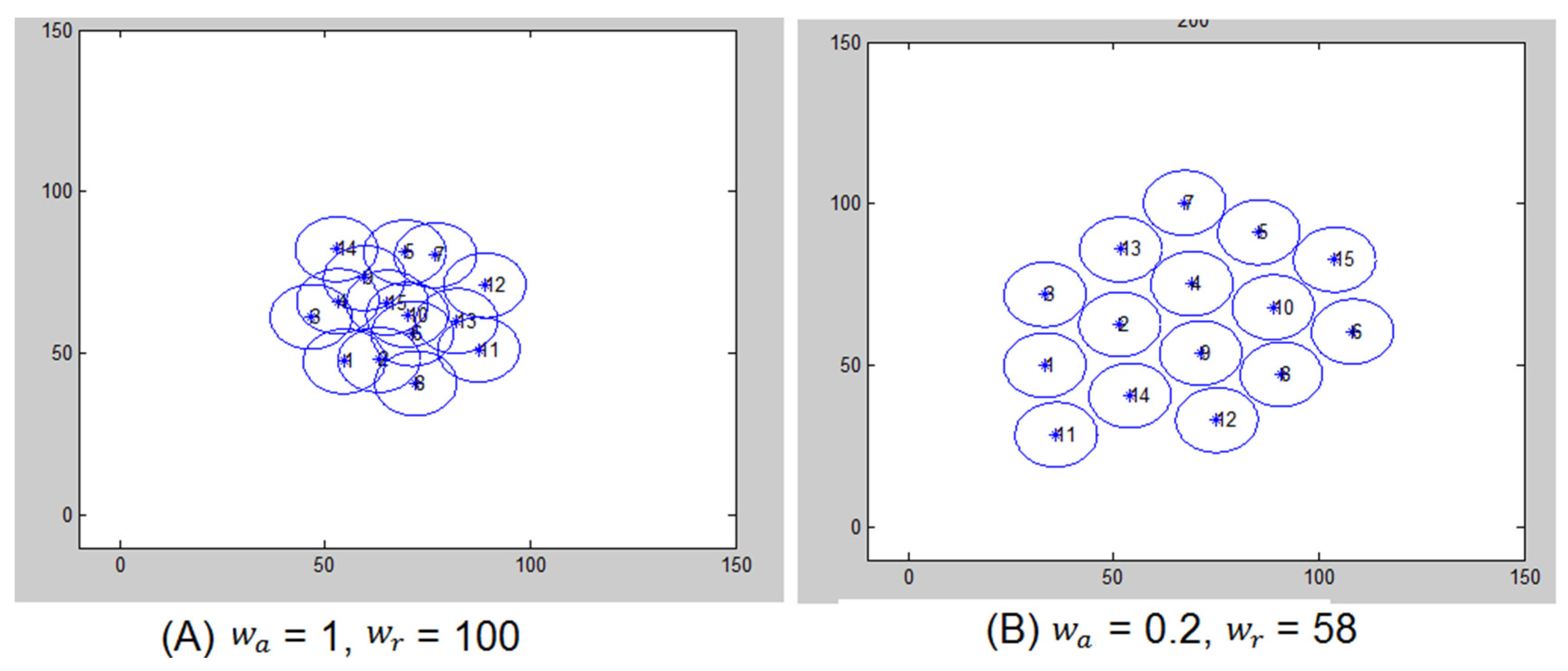
Figure 1D, where the attractive force considers the number of robots as well as their communication range. On the other hand, if the number of robots is small, it is recommended to set the attractive force high in order to keep the robots close to each other. In
Figure 2B, we show different settings for
under a small number of robots. We can observe that setting
to be high is suitable but only to a certain level. Otherwise, as in
Figure 2A, it causes the robots to attract each other more. Therefore, they will not be spread uniformly.
So, in order to accommodate all the situations mentioned above, we propose the following setting for the attractive force:
where
is the distance that should be kept between each two robots at the final deployment which is
,
is the communication range of each robot which is
, K>2, α is an arbitrary factor but a predetermined tuning parameter (in the presented experiments α =3/2), and
J represents a number of mobile robots within the communication range. Increasing the value of α increases the repulsive force and decreases the attractive force. Decreasing the value of α decreases the repulsive force and increases the attractive force.
For some applications, such as rescue and search operations, it is preferred to deploy more robots in certain locations than others do. In this case, the location that should attract more robots, the setting of
should be higher relative to other robots’ setting of
, and proportional to the preference that needs to be given to that point. As seen in
Figure 3, points 26 and 27 have different preferences, and the preferential of point 26 needs to be higher than that of point 27. As a result, point 26 was able to attract more robots to its vicinity. Higher attractive force is given to a point by multiplying its
by a factor relative to the attraction of the others. For example, in
Figure 3, point 26 and 27 require a demand of 10 and 5 robots, respectively. So, point 26 has
multiplied by 10, while, point 27 has
multiplied by 5.
3.2. Repulsive Force
We have discussed the key role of attractive force in a virtual force approach; however, this approach still depends on another factor: the repulsive force (
). Typically, the repulsive force is triggered when the robots are close to each other by less than the distance threshold. The setting of this parameter has a great influence on the stability of the virtual force approach. If this parameter is set to a high value, it will have a different impact if the number of robots is high or low. If the number of robots is low and
is high relative to their number, it will cause them to become out of range of each other. This kind of behavior is solved partially by limiting the step size that a robot can move at one time. On the other hand, if the number of robots is high, and the repulsive force is high beyond a certain level (i.e., >1000), it will cause the robots to move in clusters as shown in
Figure 4A–C. Therefore, governing the value of
has the same impact of
. As a result, we propose that
should be directly proportional to the number of robots within the communication range, as shown in equation (4).
As the number of robots increases, the repulsive force should increase to let them spread throughout the area and maximize the coverage.
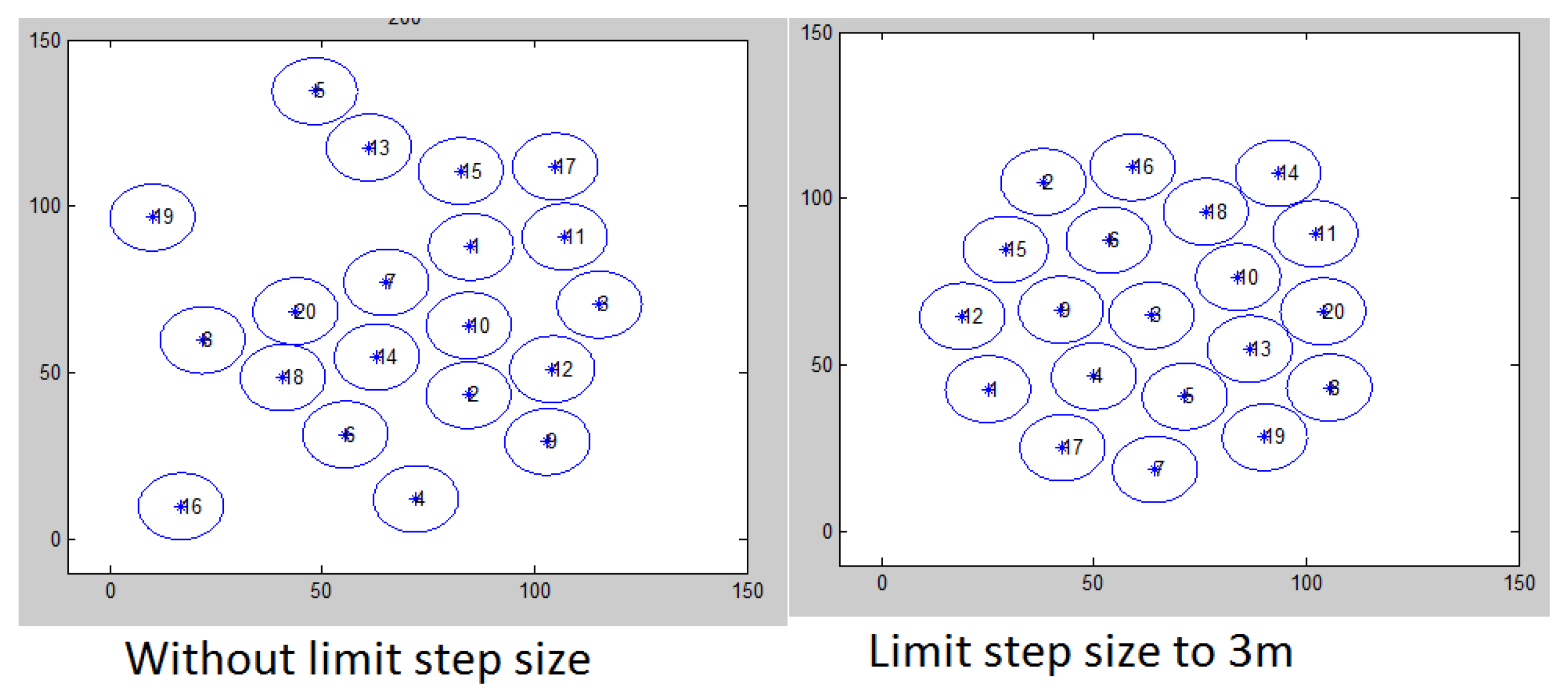
In all the above settings, the step size should be limited; otherwise, the robots will not stabilize at all. For example, if robots are very close to each other, the repulsive force will be high and could cause them to move a larger distance, which would result in robots getting out of range of each other. In other cases, it could trigger an oscillation cycle of high attractive force, then high repulsive force, and so on. Hence, the network deployment will not stabilize at all. This effect is shown in
Figure 5, where the number of robots is 20. It is recommended that the step size should be set to be less than
; however, if its value is too small, it may slow down the convergence and trigger a high number of communication messages. Limiting step size also produces the required uniform distribution of robots and reasonable movements.
3.3. Energy-Aware Virtual Force Approach (EAVF)
In order to consider the level of energy that each robot has, we integrate the remaining energy of each robot in the virtual force calculation. So, the virtual force computation will correspond to the following equation:
where
is the energy of the current robot, while
is the energy of the neighboring robot. Therefore, the energy of each pair of robots is considered such that if the robots have the same energy level, then the original VF is applied. Otherwise, the one with higher energy will get a higher VF than those with lower energy and vice versa. Additionally, since we consider that there is a limit on the step size that a robot can move, this limit will be related to the level of energy of the robot and its neighbors as a summation of the difference between a robot’s energy and its neighbors’ energy as follows:
where
is the number of neighboring robots. We have the following case:
If ≤ 10% of the maximum energy, the robot moves a very small step and keeps participating in virtual force messages.
If ≥ % of the , then the step size is increased by a certain value.
If % of the, then the step size is decreased by a certain value. Otherwise, the step level stays as the default value.
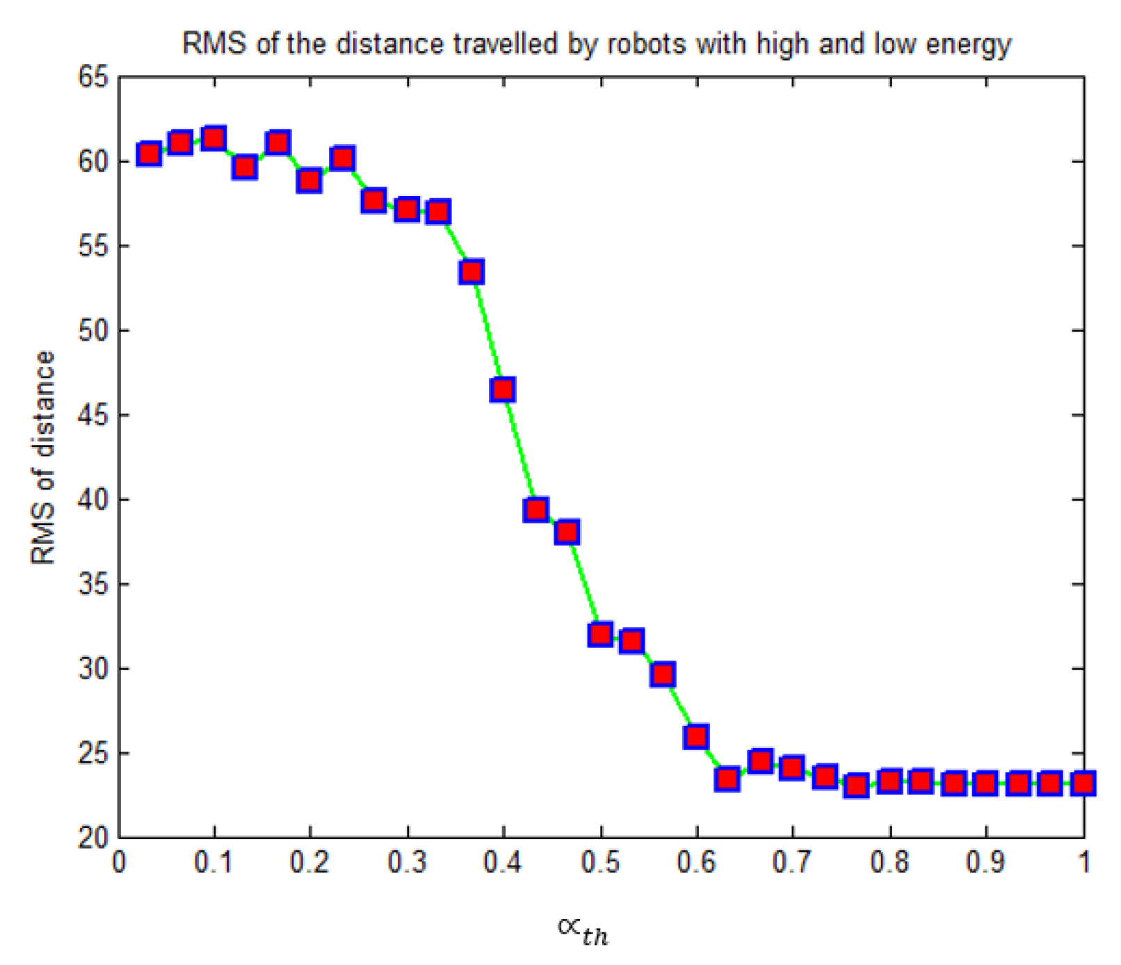
The value of
is selected based on conducting different experiments. We have tested a range of values from 0.03 to 1. For each value, the number of robots varies from 6 to 30, half of them with low energy and the second half with high energy. Then, we measure the sensitivity by computing the root mean square (RMS) of the difference between the average traveled distance by low-energy robots and high-energy robots.
Figure 6 shows that increasing the level of the threshold gives a good result until it reaches around point 0.3, where the RMS starts to decline. This gives us an insight of how we can choose the threshold value to attain the best result.
4. Results and Discussion
We have tested the above formulas of
and
on different scenarios with different requirements. Moreover, we have tested the virtual force approach with different settings of
to study its relationship with a different number of robots. As we can see from the results in
Figure 7 and
Figure 8, for different numbers of robots, there is a safe region where the value of
provides the highest performance in terms of coverage maximization. If we would like to make some robots preferential over others, the other robots should have the same
value and the
of the preferred robots should be set higher relative to how much preference we would like to set.
The proposed formula for
is also tested under different variations and different scenarios. We see in
Figure 6 and
Figure 7 that when a small number of robots is used, we have a limit on how much the attractive force could be set to. On the other hand, increasing the number of robots implies increasing the repulsive force to a certain level; after that the performance of the network deteriorates in terms of coverage. The proposed formulas for
and
fall in the safe region for any number of robots, which confirms the applicability of the proposed formulas and they can adapt to different kinds of scenarios.
Moreover, we compare our proposed settings to the settings mentioned in reference [
3] where it is suggested that the attractive force should be much smaller compared to the repulsive force. We see that our setting is able to reach the maximum possible coverage while the arbitrary small value for the attractive force and high value for the repulsive force work for some scenarios but not for all, as illustrated in
Figure 9.
To consider practical aspects of antenna coverage, we have tested our approach assuming a circular coverage for the communication with randomness (normal distribution with mean =
, and variance = 0.05
) added to the circumference of
. The result is depicted in
Figure 10. We can see that the variation added to the communication radius did not affect the overall coverage achieved.
In order to investigate the effect of robot remaining energy on the deployment process, we have conducted some experiments using the original virtual force and the energy-aware virtual force. We find that the proposed approach is able to balance the energy consumption among the robots with high remaining energy and those with a low level of remaining energy, as in
Figure 11. In the original virtual force, all robots, regardless of their remaining energy, have traveled almost the same distance, while with the energy-aware approach, the robots with a low energy level (EAVF-low) have traveled less distance compared to those with a high energy level (EAVF-high).
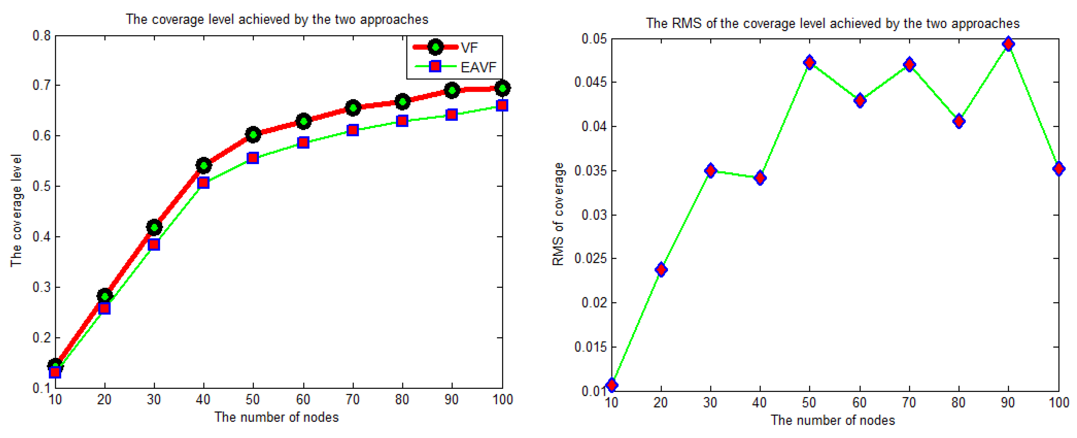
Additionally, we can observe that applying the energy-aware version has minimal effect on the coverage level achieved of multi-robot deployment. In both approaches, almost the same level of coverage has been achieved, as shown in
Figure 12B.
6. Virtual Force Testbed Using EV3 Robots
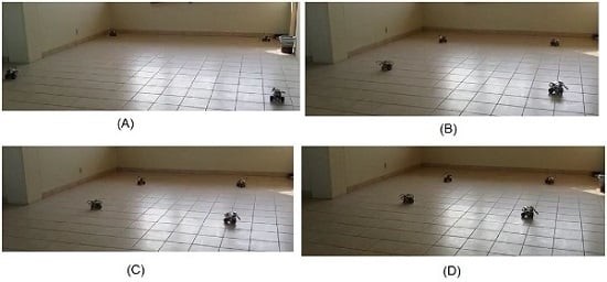
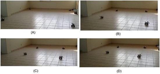
In order to test the proposed setting of and, we have carried out several experiments using a testbed consisting of six Lego Mindstorm EV3 robots. We installed a tiny Linux distribution (leJOS) on a microSD in order to implement our algorithm in each robot and to be able to program it using java. The experiments have been conducted on two scenarios: one scenario where the robots are close to each other and repulsive force is expected to work in this case, and the second scenario where the robots are far from each other and the attractive force is supposed to be triggered for a scenario.
Figure 14 shows snapshots for the first scenario where the robots started away from each other as in
Figure 14A, and the requirements of this scenario is to keep the distance between the robots to within two meters. So, the robots used virtual force to achieve the required deployment as in
Figure 14D. In contrast,
Figure 15 shows snapshots for the repulsive force application. The robots used virtual force until they reached the uniform distribution shown in
Figure 15D. All the presented experiments use the proposed setting of
and
presented in this paper. YouTube videos of these two experiments are available at KFUPM Robotics [
20].
7. Conclusion
In this work, we have investigated and provided guidelines on how to set virtual force parameters in order to accommodate different scenarios. We proposed two calibrations: one for the attractive force and one for the repulsive force which factors in system parameters such as the number of robots while computing attractive/repulsive forces. Moreover, we have presented an energy-aware version of virtual force that is able to balance the remaining energy among robots and, at the same time, achieve the required deployment. The proposed settings have been tested in simulation and in real experimentation using Lego EV3. The results showed that, under the proposed settings, the robotic network reached the ultimate coverage level, adapted to the number of nodes and area size, preferential points demand, and, finally, balanced energy consumption.


