
Analysis and Design of a DSTATCOM Based on Sliding Mode Control Strategy for Improvement of Voltage Sag in Distribution Systems


Abstract
:1. Introduction
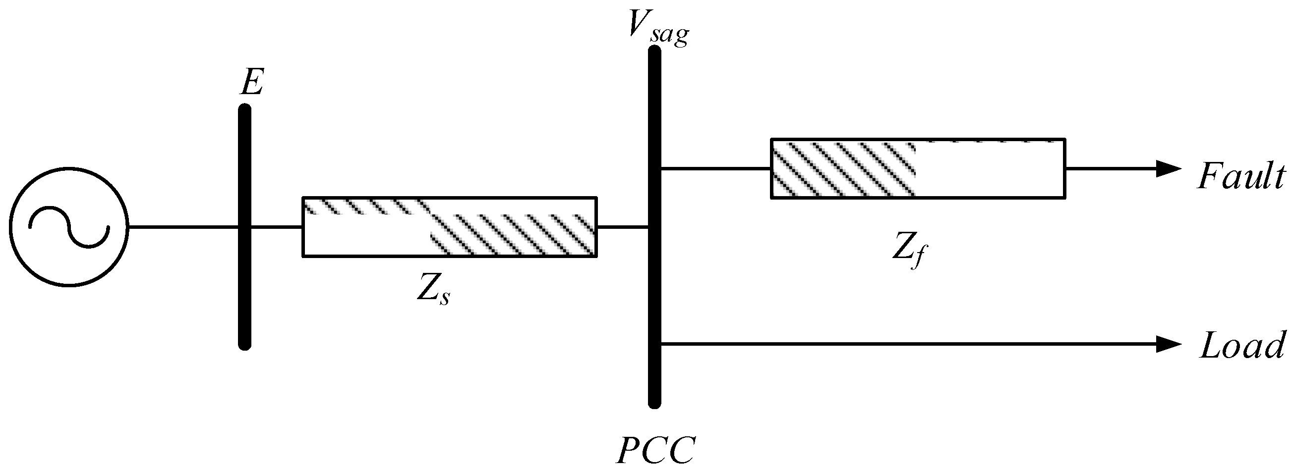
2. Voltage Sag
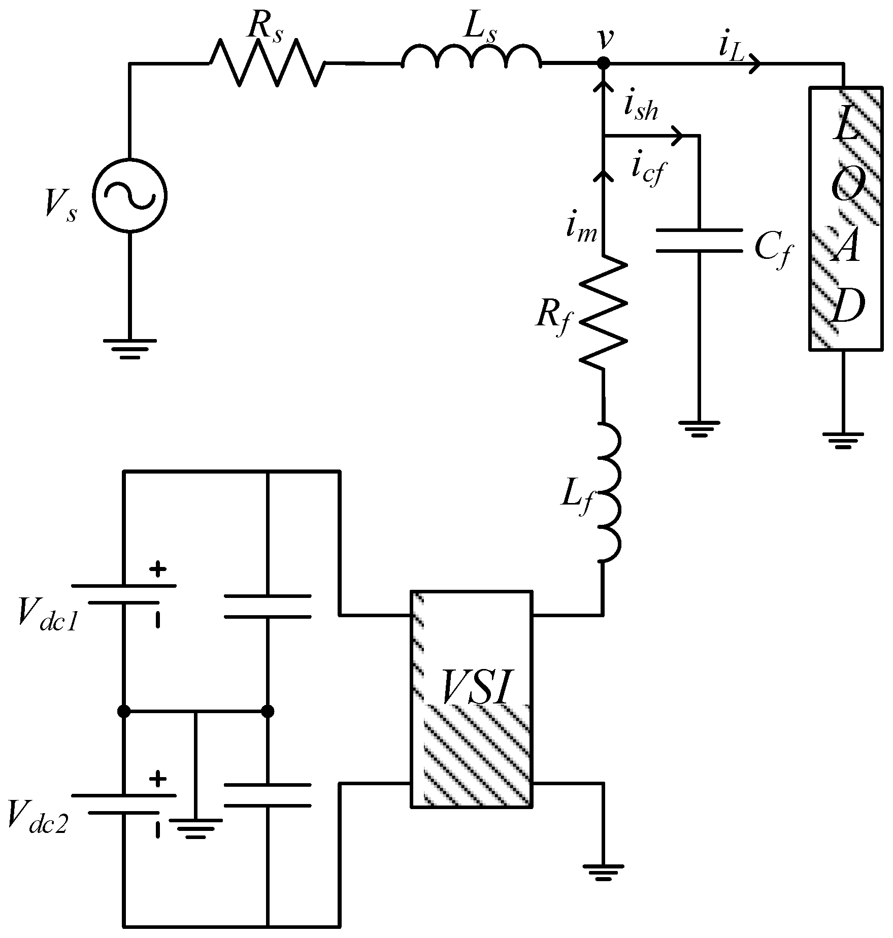
3. DSTATCOM Structure
4. Sliding Mode Control
4.1. System Equations
4.2. Sliding Surface Selection and Sliding Mode Existence Evaluation
- -
- if S > 0 and Ṡ < 0, then S(Ve,t) will decrease towards zero.
- -
- if S < 0 and Ṡ > 0, then S(Ve,t) will increase towards zero.
4.3. Determination of Control Law
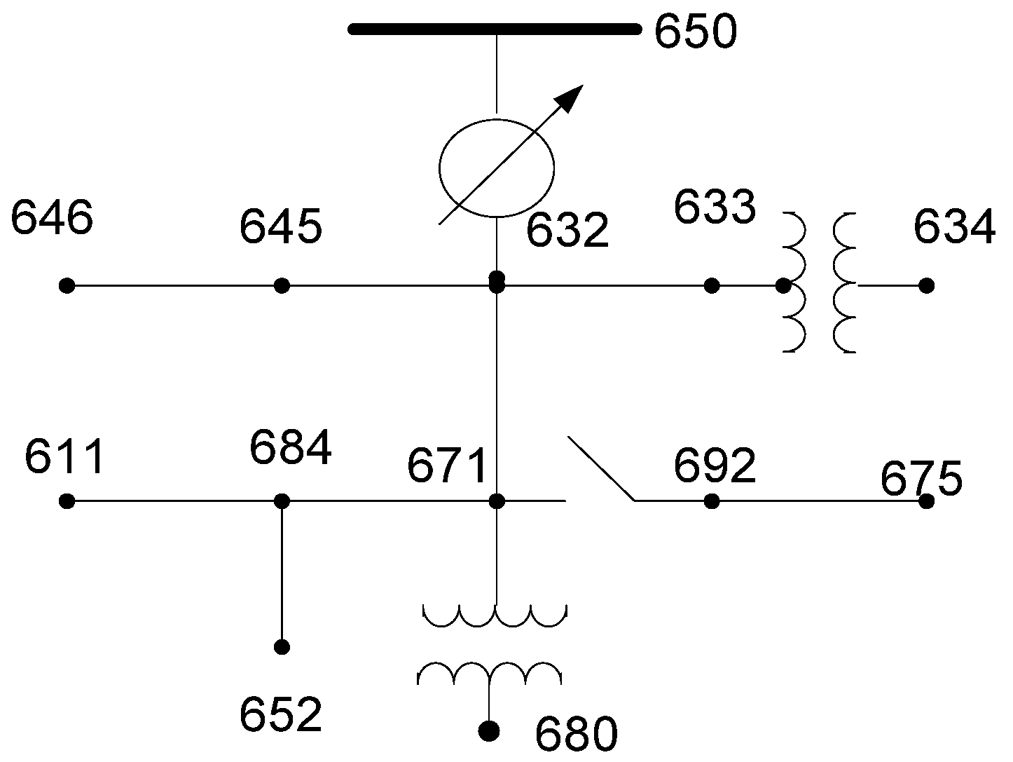
5. Simulation Results
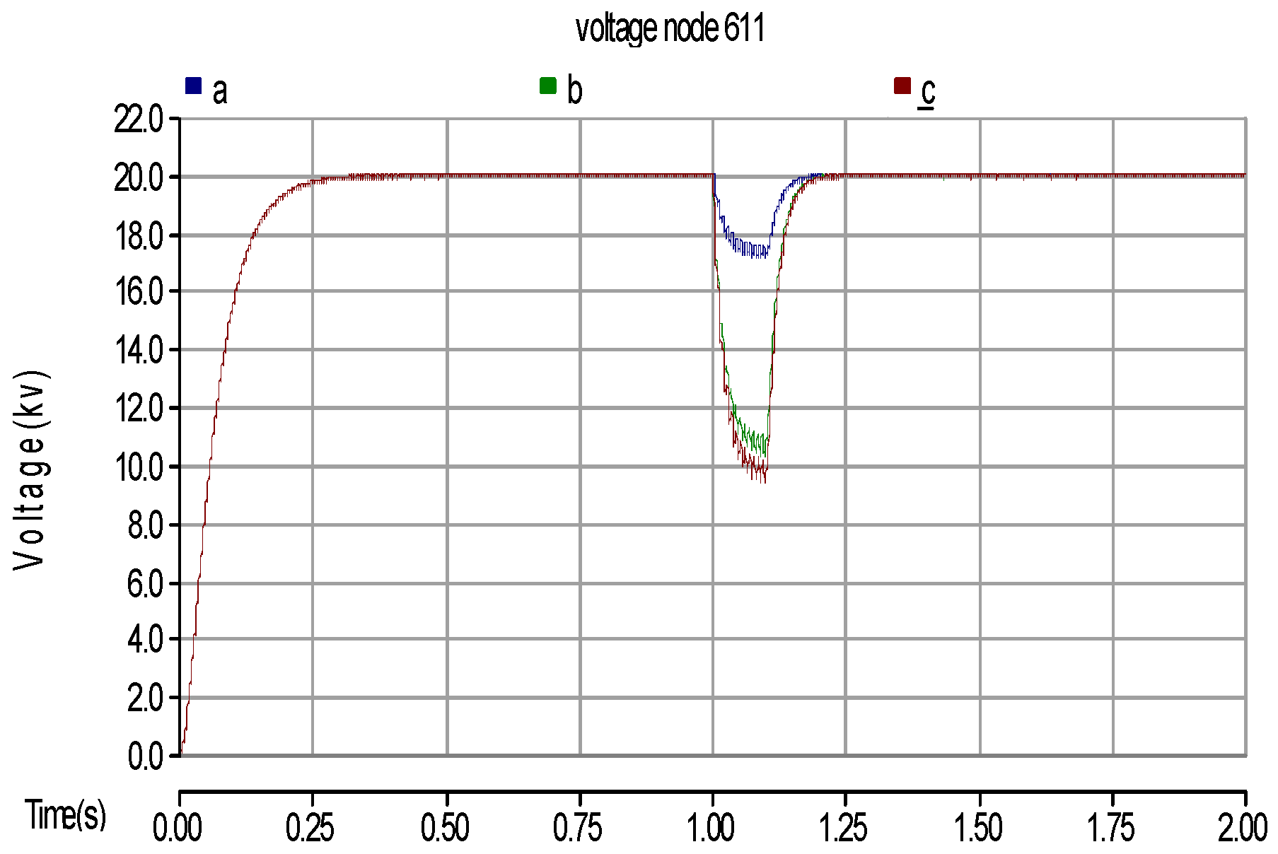
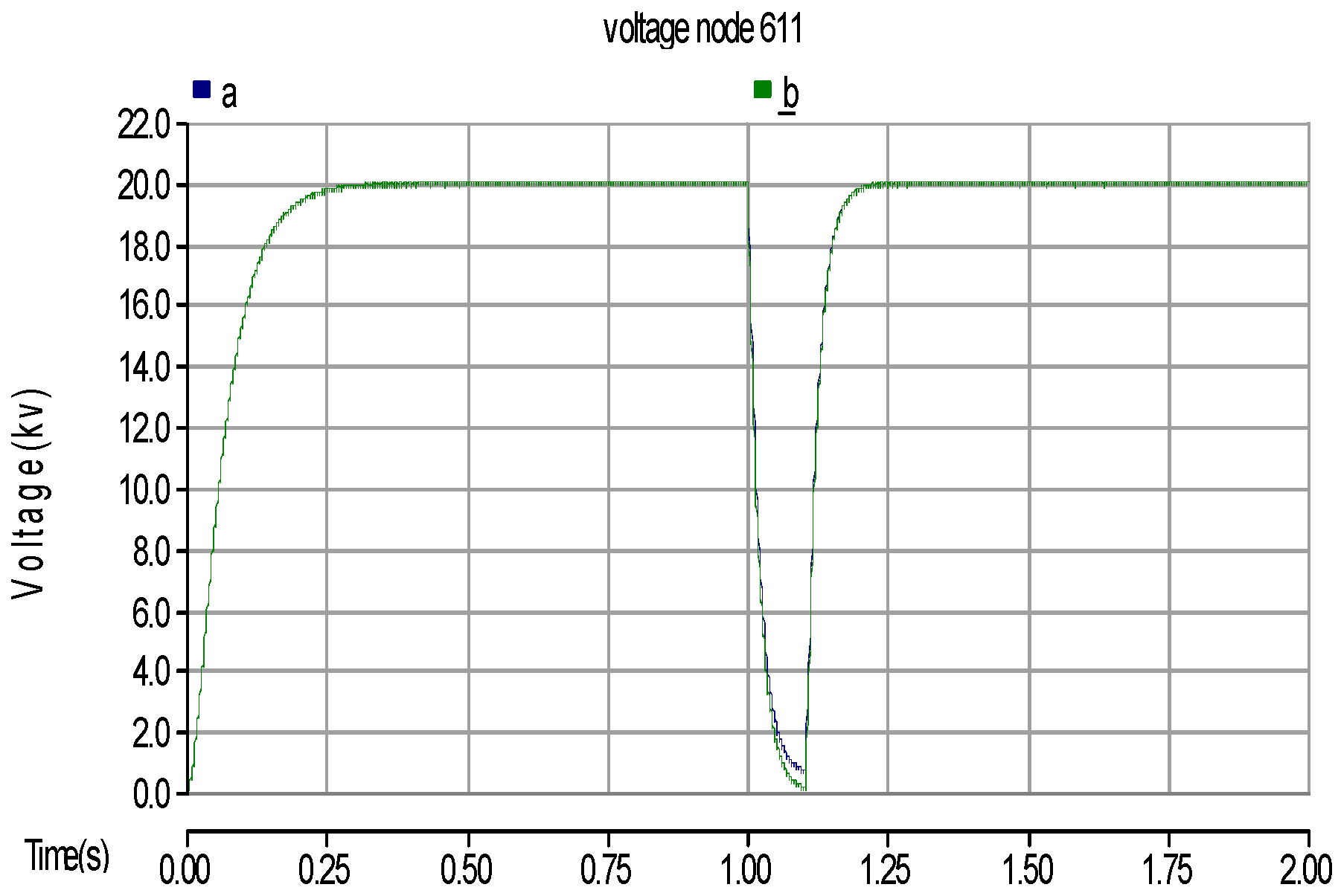
5.1. Voltage Sag
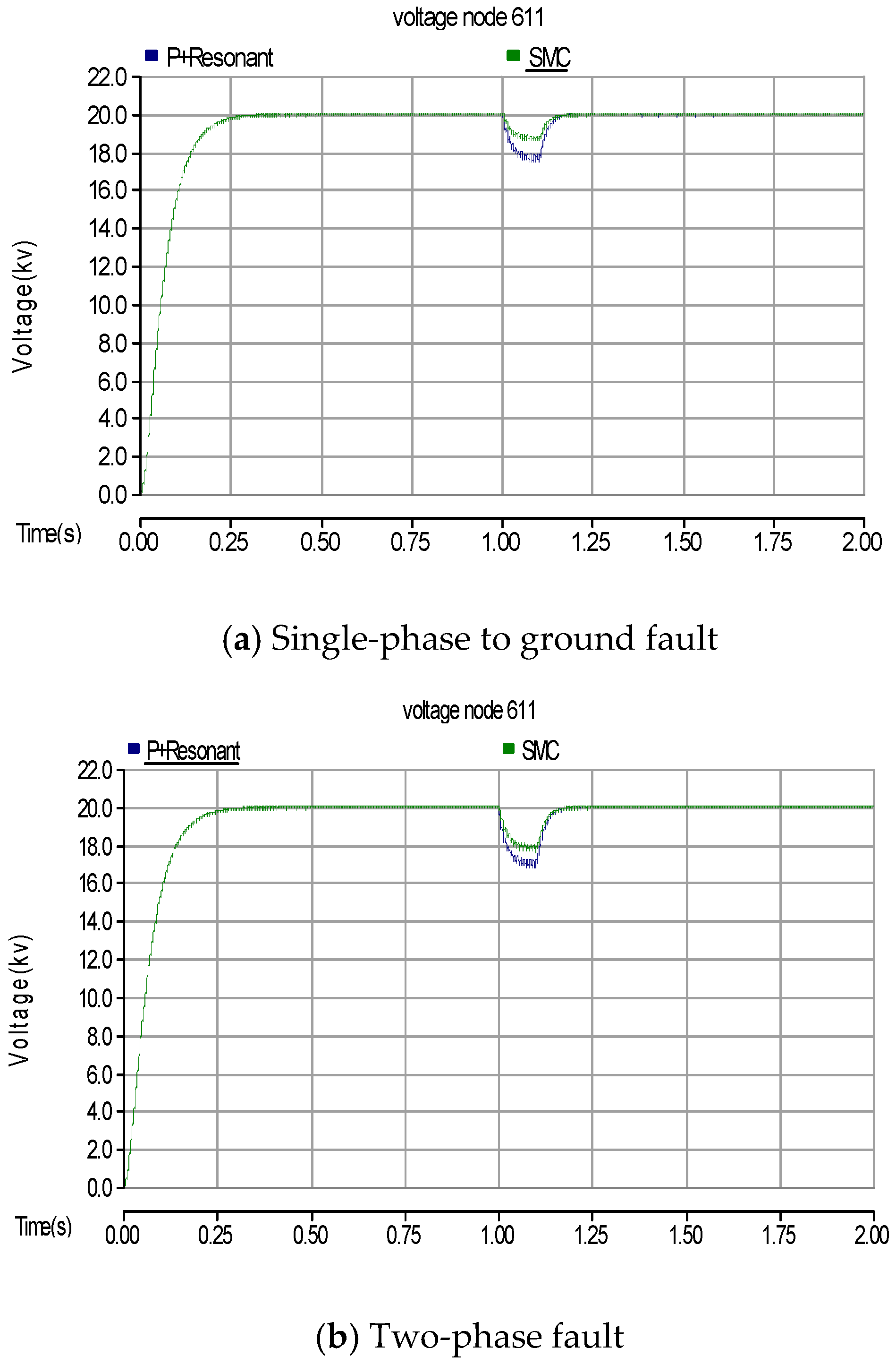
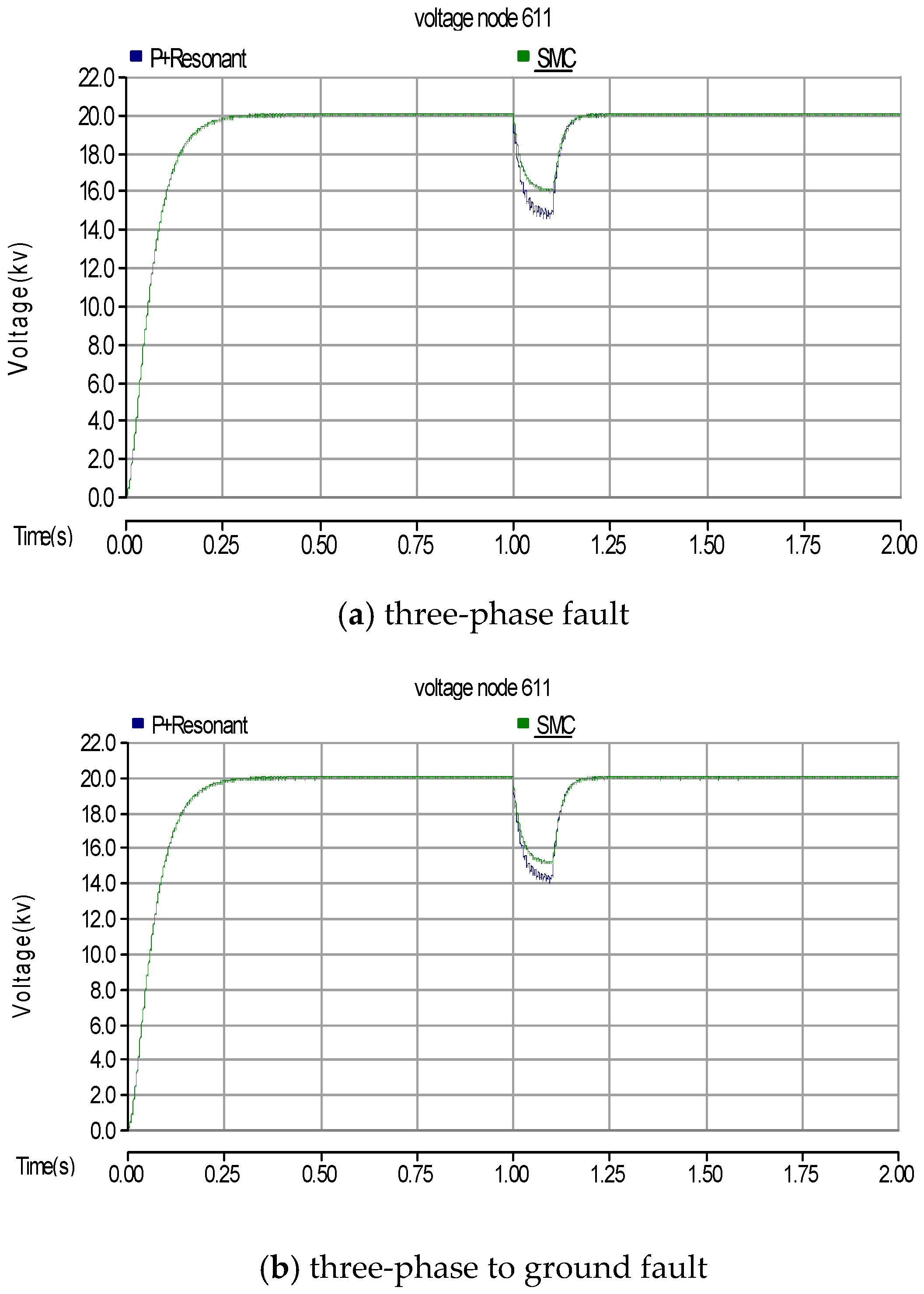
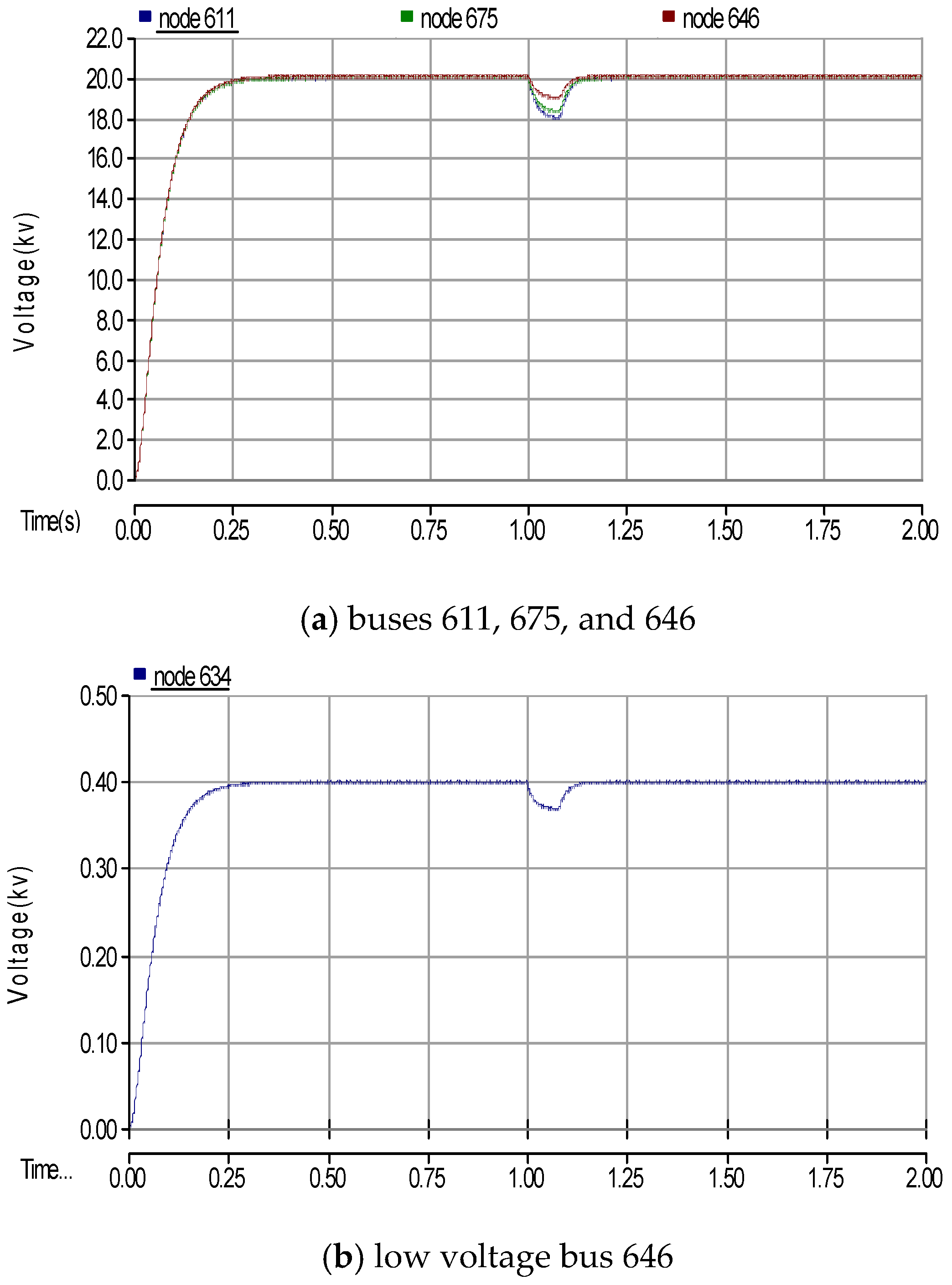
5.2. Voltage Sag Compensation
6. Conclusions
Author Contributions
Conflicts of Interest
References
- Shahgholian, G.; Movahedi, A. Power system stabiliser and flexible alternating current transmission systems controller coordinated design using adaptive velocity update relaxation particle swarm optimisation algorithm in multi-machine power system. IET Gener. Transm. Distrib. 2016, 10, 1860–1868. [Google Scholar] [CrossRef]
- Shahgholian, G.; Haghjoo, E.; Seifi, A.; Hassanzadeh, I. The improvement DISTATCOM to enhance the quality of power using fuzzy-neural controller. J. Intell. Proc. Electr. Technol. 2011, 2, 3–16. [Google Scholar]
- Goswami, A.K.; Gupta, C.P.; Singh, G.K. Minimization of voltage sag induced financial losses in distribution systems using FACTS devices. Electr. Power Syst. Res. 2011, 81, 767–774. [Google Scholar] [CrossRef]
- Naidu, S.R.; de-Andrade, G.V.; da-Costa, E.G. Voltage sag performance of a distribution system and its improvement. IEEE Trans. Ind. Appl. 2012, 48, 218–224. [Google Scholar] [CrossRef]
- Bingham, R.P. Measurement instruments for power quality monitoring. In Proceedings of the IEEE/PES, Chicago, IL, USA, 21–24 April 2008; pp. 1–3.
- IEEE Std. 1159–1995. IEEE Recommended Practice for Monitoring Electric Power Quality, Technical Report; The Institute of Electrical and Electronics Engineers, Inc.: New York, NY, USA, 1995. [Google Scholar]
- Heine, P.; Khronen, M. Voltage sag distributions caused by power system faults. IEEE Trans. Power Syst. 2003, 18, 1367–1373. [Google Scholar] [CrossRef]
- Nagpal, M.; Martinich, T.G.; Moshref, A.; Morison, K.; Kundur, P. Assessing and limiting impact of ttransformer inrush current on power quality. IEEE Trans. Power Deliv. 2006, 21, 890–896. [Google Scholar] [CrossRef]
- Martinez, J.A.; Arnedo, J.M. Voltage sag studies in distribution networks—Part I: System Modeling. IEEE Trans. Power Deliv. 2006, 21, 338–345. [Google Scholar] [CrossRef]
- Khanh, B.Q.; Dong-Jun, W.; Seung, M. Fault distribution modeling using stochastic bivariate models for prediction of voltage sag in distribution systems. IEEE Trans. Power Deliv. 2008, 23, 347–354. [Google Scholar] [CrossRef]
- Milanovic, J.V.; Zhang, Y. Modeling of FACTS devices for voltage sag mitigation studies in large power systems. IEEE Trans. Power Deliv. 2010, 25, 3044–3052. [Google Scholar] [CrossRef]
- Basu, M.; Das, S.P.; Dubey, G.K. Investigation on the performance of UPQC-Q for voltage sag mitigation and power quality improvement at a critical load point. IET Gener. Transm. Distrib. 2008, 2, 414–423. [Google Scholar] [CrossRef]
- Faiz, J.; Shahgholian, G.; Ehsan, M. Stability analysis and simulation of the single-phase voltage source UPS inverter with two-stage cascade output filter. Eur. Trans. Electr. Power 2008, 18, 29–49. [Google Scholar] [CrossRef]
- Azpeitia, M.A.P.; Fernandez, A.; Lamar, D.G.; Rodriguez, M.; Hernando, M.M. Simplified voltage-sag filler for line-interactive uninterruptible power supplies. IEEE Trans. Ind. Electron. 2008, 55, 3005–3011. [Google Scholar] [CrossRef]
- Shahgholian, G.; Movahedi, A.; Faiz, J. Coordinated design of TCSC and PSS controllers using VURPSO and genetic algorithms for multi-machine power system stability. Int. J. Control Autom. Syst. 2015, 13, 398–409. [Google Scholar] [CrossRef]
- Valderrábano, A.; Ramirez, J.M. DStatCom regulation by a fuzzy segmented PI controller. Electr. Power Syst. Res. 2010, 80, 707–715. [Google Scholar] [CrossRef]
- Masdi, H.; Mariun, N.; Mahmud, S.; Mohamed, A.; Yusuf, S. Design of a prototype DSTATCOM for voltage sag mitigation. In Proceedings of the IEEE/NPEC, Chicago, IL, USA, 28–29 June 2004; pp. 61–66.
- Elnady, A.; Salama, M.M.A. Unified approach for mitigating voltage sag and voltage flicker using the DSTATCOM. IEEE Trans. Power Deliv. 2005, 20, 992–1000. [Google Scholar] [CrossRef]
- Blazic, B.; Papic, I. Improved D-Statcom Control for Operation with Unbalanced Currents and Voltages. IEEE Trans. Power Deliv. 2006, 21, 225–233. [Google Scholar] [CrossRef]
- Molina, M.G.; Mercado, P.E. Control design and simulation of DSTATCOM with energy storage for power quality improvements. In Proceedings of the IEEE/PEC, Caracas, Venezuela, 15–18 August 2006; pp. 1–7.
- Ortega, R.; Trujillo, C.; Garcera, G.; Figueres, E.; Carranza, O. A PI-P+Resonant controller design for single phase inverter operating in isolated microgrids. In Proceedings of the IEEE/ISIE, Hangzhou, China, 28–31 May 2012; pp. 1560–1565.
- Singh, B.; Arya, S.R. Adaptive theory-based improved linear sinusoidal tracer control algorithm for DSTATCOM. IEEE Trans. Power Electron. 2013, 28, 3768–3778. [Google Scholar] [CrossRef]
- Singh, B.; Arya, S.R. Back-propagation control algorithm for power quality improvement using DSTATCOM. IEEE Trans. Ind. Electron. 2013, 61, 1204–1212. [Google Scholar] [CrossRef]
- Nasiraghdam, H.; Jalilian, A. Balanced and unbalanced voltage sag mitigation using DSTATCOM with linear and nonlinear Loads. Int. J. Electr. Comput. Syst. Eng. 2007, 1, 86–91. [Google Scholar]
- Kumar, C.; Mishra, M.K. Operation and control of an improved performance interactive DSTATCOM. IEEE Trans. Ind. Electron. 2015, 62, 6024–6034. [Google Scholar] [CrossRef]
- Jain, A.; Behal, A.; Zhang, X.; Dawson, D.; Mohan, N. Nonlinear controllers for fast voltage regulation using statcoms. IEEE Trans. Control Syst. Technol. 2004, 12, 827–842. [Google Scholar] [CrossRef]
- Shahgholian, G.; Karimi, H.; Mahmoodian, H. Design a power system stabilizer based on fuzzy sliding mode control theory. Int. Rev. Mod. Sim. 2012, 5, 2191–2196. [Google Scholar]
- Bollen, M.H.J. Understanding Power Quality Problems: Voltage Sags and Interruptions; Wiley-IEEE Press: New York, NY, USA, 1999. [Google Scholar]
- Nam, S.R.; Sohn, J.M.; Kang, S.H.; Park, J.K. Ground-fault location algorithm for ungrounded radial distribution systems. J. Electr. Eng. 2007, 89, 503–508. [Google Scholar] [CrossRef]
- Mokhtari, M.; Khazaie, J.; Nazarpour, D.; Farsadi, M. Interaction analysis of multifunction FACTS and D-FACTS controllers by MRGA. Turk. J. Electr. Eng. Comput. Sci. 2013, 21, 1685–1702. [Google Scholar] [CrossRef]
- Karmiris, G.; Tsengenes, G.; Adamidis, G. A multifunction control scheme for current harmonic elimination and voltage sag mitigation using a three phase three level flying capacitor inverter. Simul. Model. Pract. Theory 2012, 24, 15–34. [Google Scholar] [CrossRef]
- Shahgholian, G.; Rajabi, A.; Karimi, B. Analysis and design of PSS for multi-machine power system based on sliding mode control theory. Int. Rev. Electr. Eng. 2010, 4, 2241–2250. [Google Scholar]
- Carpita, M.; Marchesoni, M. Experimental study of a power conditioning system using sliding mode control. IEEE Trans. Power Electron. 1996, 11, 731–741. [Google Scholar] [CrossRef]
- Guptaand, R.; Ghosh, A. Frequency-domain characterization of sliding mode control of an inverter used in DSTATCOM application. IEEE Trans. Circuits Syst. 2006, 53, 662–676. [Google Scholar]
- Bajpai, R.S.; Gupta, R. Sliding mode control of converter in distributed generation using DSTATCOM. In Proceedings of the IEEE/ICPCES, Allahabad, India, 28 December–1 January 2010; pp. 1–7.


| Bus Number | 650 | 634 | 646 | 675 | 611 | |
|---|---|---|---|---|---|---|
| Short Circuit Type | ||||||
| Single-phase to ground | 19.950 | 0.379 | 19.164 | 17.233 | 17.190 | |
| Two-phase | 19.941 | 0.373 | 18.243 | 10.579 | 10.470 | |
| Two-phase to ground | 19.935 | 0.364 | 18.101 | 9.791 | 9.669 | |
| Three-phase | 19.914 | 0.335 | 17.793 | 0.385 | 0.363 | |
| Three-phase to ground | 19.892 | 0.319 | 17.685 | 0.141 | 0.135 | |
| Bus Number | Control System | 650 | 634 | 646 | 675 | 611 | |
|---|---|---|---|---|---|---|---|
| Short Circuit Type | |||||||
| Single-phase to ground | SMC | 19.983 | 0.390 | 19.531 | 18.413 | 18.407 | |
| P+Resonant | 19.963 | 0.382 | 19.241 | 17.601 | 17.589 | ||
| Two-phase | SMC | 19.976 | 0.384 | 18.984 | 17.718 | 17.705 | |
| P+Resonant | 19.957 | 0.377 | 18.442 | 16.891 | 16.998 | ||
| Two-phase to ground | SMC | 19.968 | 0.373 | 18.525 | 17.008 | 16.922 | |
| P+Resonant | 19.949 | 0.369 | 18.229 | 16.423 | 16.313 | ||
| Three-phase | SMC | 19.959 | 0.359 | 17.992 | 16.023 | 15.995 | |
| Control system | 650 | 634 | 646 | 675 | 611 | ||
| Three-Phase to ground | SMC | 19.959 | 0.359 | 17.992 | 16.023 | 15.995 | |
| P+Resonant | 19.940 | 0.347 | 17.851 | 14.889 | 14.908 | ||
| Bus Number | Control System | 650 | 634 | 646 | 675 | 611 | |
|---|---|---|---|---|---|---|---|
| Short Circuit Type | |||||||
| Three-Phase to ground | SMC | 19.948 | 0.347 | 17.841 | 15.482 | 15.135 | |
| P+Resonant | 19.921 | 0.331 | 17.716 | 14.304 | 14.361 | ||
© 2016 by the authors; licensee MDPI, Basel, Switzerland. This article is an open access article distributed under the terms and conditions of the Creative Commons Attribution (CC-BY) license (http://creativecommons.org/licenses/by/4.0/).
Share and Cite
Shahgholian, G.; Azimi, Z. Analysis and Design of a DSTATCOM Based on Sliding Mode Control Strategy for Improvement of Voltage Sag in Distribution Systems. Electronics 2016, 5, 41. https://doi.org/10.3390/electronics5030041
Shahgholian G, Azimi Z. Analysis and Design of a DSTATCOM Based on Sliding Mode Control Strategy for Improvement of Voltage Sag in Distribution Systems. Electronics. 2016; 5(3):41. https://doi.org/10.3390/electronics5030041
Chicago/Turabian StyleShahgholian, Ghazanfar, and Zahra Azimi. 2016. "Analysis and Design of a DSTATCOM Based on Sliding Mode Control Strategy for Improvement of Voltage Sag in Distribution Systems" Electronics 5, no. 3: 41. https://doi.org/10.3390/electronics5030041