1. Introduction
Upcoming 5G technology is targeting the controlling and steering of the Internet of Things (IoT) in real-time on a global scale. This will break new ground for new markets such as driverless vehicles, manufacturing, humanoid robots, and smart grids. The number of wireless devices is expected to increase by five times to up to 50 billion devices [
1]. It is generally believed that those devices will not be connected in the same manner as current devices are connected today. Centralized systems will collapse in terms of capacity, while distributed systems appear as an alternative. Therefore, we believe mesh technologies will play a major role in the communication architecture in future systems. Mesh technology has been known for sensor and ad hoc networks or mobile cloud scenarios, but the technical requirements on 5G mesh-based communication systems are dramatically increasing. Future mesh networks need to support high data rate, low latency, security, network availability and heterogeneous devices to ensure high Quality of Experience (QoE) for the final user. In state-of-the-art systems, those requirements are traded-off with each other, but in the 5G context, we cannot do this anymore.
Introduced by Ahlswede et al. [
2], network coding constitutes a paradigm shift in the way that researchers and industry understand and operate networks, by changing the role of intermediate relays in the process of transmission of information. Relays are no longer limited to storing and forwarding data, but also take part in the coding process, through a process called recoding, where the relay generates new linear combinations of incoming coded packets without previously decoding the data. Network coding allows the increase of throughput, reliability, security and delay performance of the networks. In previous works, we have shown that Random Linear Network Coding (RLNC) [
3,
4] is able to satisfy the aforementioned technical requirements. We have actually shown how to increase the throughput [
5], reduce the delay [
6] or support heterogeneity for coding enabled communication nodes [
7].
In our prior works, the C++11 Kodo library [
8] was used as the common building block containing the basic RLNC functionalities. Most of the work was focusing on small mesh networks with a handful of communication nodes, though the expected scenarios are fairly beyond this order of magnitude. Despite this successful deployment in real systems, many of these protocols and contributions have been implemented in separate testbeds and the experiences are hard to reproduce. Deploying a large-scale and configurable testbed for networking and storage can be challenging, not only due to the inherent costs of the hardware, but due to maintenance challenges and ability to replicate results consistently. The latter requires not only the devices to run the same Operating System (OS), but also have exactly the same configurations and software packages. There is a need to evaluate large-scale network deployments of low-cost devices in a quick, easy-to-deploy, reproducible and maintainable fashion.
The emergence of powerful and inexpensive single-board computers opens new possibilities in this area. By running a standard OS, they allow implementations that are compatible with higher end devices. In addition, they utilize stable software supported by their communities. For example, the Iridis-pi platform [
9] provides a detailed description of a Raspberry Pi (Raspi) [
10] testbed ideal for educational applications. Here, the authors present computational speed benchmarks, inter-node communication throughput and memory card writing speeds for data storage to assess the testbed performance. This work indicates only a basic description of how to set up the required software and also mentions that its maintenance could be time-consuming. Moreover, this work does not consider possible network coding applications. Different studies of IoT applications consider using the Raspi for data processing: In [
11], the Raspi is the processing unit that coordinates and controls the activity of an isle of lamps on a public road and reports it to a monitoring center. A use case regarding remote environment surveillance using the Raspi and the Arduino [
12] technologies is presented in [
13]. Here, both devices report air pressure, humidity and temperature of the locations of cultural paintings plus high-resolution images of the paintings themselves. This data is sent to a monitoring center to ensure the preservation of the paintings. Furthermore, authors in [
14] consider FingerScanner, a technology that utilizes the Raspi to act as the data server in a finger scanning application that collects the fingerprints. Even though all these applications consider the use of the Raspi as a core block, they provide few to no descriptions of their procedures to configure the Raspi. These applications become cumbersome to maintain as their considered systems could potentially scale when aiming to serve more users. The current way that the data is sent in the considered networks for these IoT applications will not be feasible in future 5G systems as mentioned previously.
Given this set of specific needs, in this work, we present the design, key step-by-step instructions and mechanisms to setup, configure and maintain an inexpensive testbed using potentially several Raspi devices for networking (wireless or wired) and storage applications including RLNC functionalities into the testbed through Kodo. The architecture itself is not bounded to the networking area and can be used for other applications that require replicable results with the Raspi. Our work for the testbed procedure is organized as follows:
Section 2 introduces the testbed system. In
Section 3, we provide details about the testbed setup, scripts, configuration files and connectivity. In
Section 4, we elaborate on the need and setup for an overlay filesystem for our testbed in order to have both persistent and non-persistent data on it as an optional step.
Section 5 describes a set of automation and monitoring tools that can be included in the testbed to simplify the execution of routinary and repetitive tasks.
Section 6 elaborates on the compilation of the Kodo library for the Raspi. Conclusions and future work are reviewed in
Section 7. Finally, a set of alternative commands, in case the ones presented in this work might not be executed, are discussed in the Appendices.
2. Testbed Overview and Design Criteria
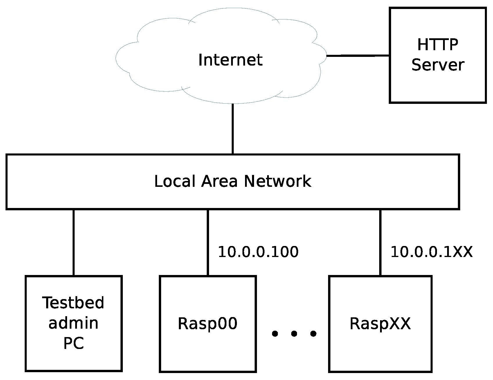
A sketch of the testbed is depicted in
Figure 1. The testbed consists of up to 100 Raspis of different models. More specifically, in our design, we consider: Raspberry Pi 1 model B rev. 2, Raspberry Pi 2 model B V1.1 and Raspberry Pi 3 model B V1.2. All Raspis are each equipped with a 8 GB Secure Digital (SD) memory card, a wired and wireless network interface and a power supply. All the Raspi are connected to a common Local Area Network (LAN) that provides internal and external connectivity. Without loss of generality, in our case, they are connected to a university network using their wired Ethernet interface that is named
eth0 according to the legacy naming convention of Ethernet interfaces in Linux [
15]. We consider the university network since our testbed is used by students and academic staff to perform measurements and experimentation of controlled and reproducible scenarios as part of academic research. The testbed description and procedures for setting it up are not restricted to this academic scenario. All Raspis are configured to run a Secure Shell (SSH) daemon for easy remote access within the university network. We requested the university Information Technology (IT) department to configure the university Dynamic Host Configuration Protocol (DHCP) server to assign each Raspi a static Internet Protocol (IP) address. This eliminates the demand for monitors and keyboards with the Raspis for non-graphical applications. Finally, our design aims to configure all Raspis identically from a customized bootable image in their respective memory cards, while still allowing the end-users to store files locally in each of the Raspis.
We will refer to the testbed administrator as the person(s) in charge of setting up and configuring the testbed with administrator privileges from the OS point of view. The setting and configuration procedures are performed by the testbed administrator in a PC running a Linux distribution as shown in
Figure 1. Although in principle the administrator Linux distribution is not a restriction, we present our procedure in a Debian-based Linux distribution. Our basic design considers to create a customized image to store it later on a memory card for each Raspi. Once configured, we store the resulting image file in a Hyper Text Transfer Protocol (HTTP) server as backup and in case the testbed administrator requires the making of new changes to this file. In our case, we store all files at Zenodo [
16], but the testbed administrator should copy the our files to his/her own HTTP server to get read/write permissions. We also put all the required configuration files and scripts for the Raspis setup in the HTTP server so there is a single place where system setup is stored and could be modified. This simplifies the system maintenance, as it may not always be desirable to make persistent changes on the Raspis—for example, when different users are interested in running experiments on a rebooted testbed. We later present how to utilize stacked filesystems to enable both persistent and temporary storage to have this capability. Its purpose is to remove non-desired data after a reboot while keeping the original customized image structure. This step of the procedure is optional if the testbed administrator decides to keep only persistent changes regardless of the testbed use. Finally, we include a set of automation, monitoring and cross-compilation tools over the top of our system in order to simplify the execution of repetitive and long tasks, be able to follow the progress of long task processes and compile relevant C++ source code for the testbed administrator.
3. OS Image Setup
In this section, we review the steps to create a common OS image for all the Raspis. The image setup is composed of three major steps: select and download the OS image file, alter the image structure and configure the OS files. We proceed to detail all these steps providing brief discussions to our setup choices when required. To perform these steps, we indicate with command-line blocks the required sequential commands to be typed by the testbed administrator on his/her PC to obtain the desired setting. In all the command blocks in the paper, we indicate if a command needs to be run with root permissions (#) or common user permissions ($). These signs will prefix the commands.
3.1. OS Selection and Download
To get started, we first need to install an OS that works properly on all the Raspi models. We will download and setup the image in the testbed administrator PC using a Debian-based distribution. An alternative to this method, is to create a tailoared Linux distribution for the Raspi platform using the Yocto Project [
17]. However, this process would require assembly and compilation of all the software for the Raspi platform from scratch, which goes beyond the scope of our work. We use the popular Debian-based Raspbian Linux [
18] given that is the recommended and default OS for the Raspi. Raspbian is made available in two bundles: Raspbian and Raspbian Lite. The difference between the two is that Raspbian contains a pre-installed desktop environment for user interaction, and Raspbian Lite by default only permits interaction through a command shell. Given that the Raspis in our testbed are not connected to monitors, we decide to work with Raspbian Lite. If required, a desktop environment can be installed using the package manager later.
The latest Raspbian Lite bundle can be downloaded from the Raspbian official webpage [
18]. At the time of this writing, the latest available bundle was
2016-05-27-raspbian-jessie-lite.zip. To ensure that the content of the bundle does not change, this procedure is based on that particular version of Raspbian Lite, which we have made available at [
16]. All other files used in this paper are also available there. The testbed administrator has to move these files to his/her own HTTP server. To get started, the testbed administrator must open a Linux shell (terminal) on his/her PC and declare the environment variables shown in the command block below. We show the whole procedure by performing the role of the testbed administrator.
![Electronics 05 00067 i001]()
In this code block, the
${URL} and
${IMAGE} variables specify where the Linux bundle is located and
${WORKDIR} specifies a working directory where the Raspbian Lite bundle will be downloaded and customized. If the testbed administrator allocates his/her files into another location, then it will be required to change the
${URL} environment variable. Notice that even though we use the $ and # signs in the shell, in general, these signs will be particular to the testbed administrator OS shell. Next, we create the working directory and change to it with the
cd command. To download the image, we utilize the
wget command before unpacking the
zip file as follows:
![Electronics 05 00067 i002]()
3.2. Image Customization
After Raspbian Lite has been unpacked, there should be an
.img file in the working directory
${WORKDIR}.
fdisk can be used to display the content of the image. We parse the arguments
-u sectors to display the sizes in sectors and
-l to display the partitions within the image. The
fdisk command should output to the terminal something similar to:
![Electronics 05 00067 i003]()
The output provides relevant information about the image. The image is in total 2,709,504 sectors (1.3 GiB) in size and contains two partitions. The first partition starts at sector 8192 and the other partition starts at sector 137,216. The first partition type is FAT32 with a size of 63 MB and the second partition is of type Linux with a size of 1.2 GB. This indicates that the first partition is a boot partition, and the second one is a traditional Linux filesystem. In this case, the root filesystem, i.e., /.
3.3. Image Resizing
Given that we want to customize the root filesystem in the Raspis, we need to expand the image file since 1.2 GB might not be enough to store the existing root filesystem plus additional files and software packages. Thus, we need to increase the partition size. The following procedure illustrates how the image and its root filesystem can be expanded by one GB. First, to expand the image one GB, we execute:
![Electronics 05 00067 i004]()
Later, we use
fdisk with the same arguments as before to see that the image is now one GB larger:
![Electronics 05 00067 i005]()
Now, in the above command block output, we observe that the change has taken effect by noticing the total available image size is 2.3 GiB. To expand the root filesystem, we replace the Linux partition with a new partition one GB larger. The starting point of this new partition should be the same as the old one. We make use of
fdisk to alter the partition table in the commands below. They (i) delete partition number 2; (ii) create a new primary partition and (iii) set the new partition starting point. The new partition starting point value is 137,216 in our case; Finally, we (iv) write the new partition table to the image file. This is made as follows:
![Electronics 05 00067 i006]()
If the partitions commands were correct, the partition table should now look like the following:
![Electronics 05 00067 i007]()
3.4. Loopback Device Setup
After successfully resizing the image file, we use a loopback device to make the Raspbian image available as a block device in the filesystem. For this command to work, the testbed administrator distribution must have the
util-linux package with version 2.21 or higher. Otherwise, the
-P argument of
losetup will appear as invalid. If the version of
losetup can not be updated for some reason, an alternative option for this part is presented in
Appendix A.1 of the Appendices.
![Electronics 05 00067 i008]()
If the previous command was succesful, the
lsblk command can be used to list the available block devices in the filesystem as follows:
![Electronics 05 00067 i009]()
The image block device appears as
/dev/loop0. This block device has two partitions associated with it, e.g.,
loop0p1 and
loop0p2. Finally, we check the filesystem of the block device with
e2fsck and resize it with the
resize2fs command:
![Electronics 05 00067 i010]()
3.5. Block Device Mounting
For browsing and altering the files in the image, we mount the block device partitions into a particular path of our
${WORKDIR} in order to customize them. We mount the block device partition that contains the root filesystem and later the boot partition. This is done by creating an empty directory that is used as a mountpoint. We name it
root and create it in the working directory before mounting the root filesystem onto the mountpoint. We mount the root filesystem as follows:
![Electronics 05 00067 i011]()
The root filesystem mounted in
${ROOTDIR} already has a boot directory that can be used as the mount point for the boot partition in the block device
/dev/loop0p1. This is convenient because the final edited partition from
${ROOTDIR}/boot will be mounted on this same directory when a Raspi starts up with a memory card containing the raw final image. Hence, to mount boot partition we do:
![Electronics 05 00067 i012]()
In this way, it is now possible to change all files within the Raspbian image as desired by editing the files in ${ROOTDIR}. We take advantage of this to edit configuration files, append new files and even update and install packages.
3.6. Image OS Files and Configuration Scripts Setup
In general, the Raspis should be setup as similarly as possible. However, some particularities exist to differentiate the devices in principle. In addition, scripts containing further configurations for the Raspis are desirable to be distributed as part of the common image. Therefore, we present here the steps to setup basic properties of the Raspis and distributing configuration scripts to each of them through the image. For this, we first indicate how to obtain and put our configuration scripts in the image. Later, we describe the tasks performed by these configuration scripts. Finally, we indicate how and in which order the scripts are executed to configure all the devices. Any testbed administrator might modify or include other tasks according to his / her needs as we will show.
3.6.1. Image Default Configuration Scripts Download
In our case, we have our default configuration scripts stored in a file
rasp_config.zip located in the same URL of the HTTP server where the image was retrieved from, i.e., the one in the environment variable
${URL}. We first download this compressed file with
wget and extract it locally into our Raspbian Lite image. These commands and the output of the last one are shown as follows:
![Electronics 05 00067 i013]()
The unzippped files are one configuration file and three configuration scripts in the newly created ${ROOTDIR}/home/pi/rasp_config/ folder in the image. We describe which features that we require all the Raspis to have and how are they achieved with these configuration scripts.
3.6.2. Device Hostnames
The hostname helps the user to physically distinguish the devices from each other. In our case, we require the devices in our testbed to have different hostnames. We define the hostnames based on the Medium Access Control (MAC) addresses of the Raspis wired Ethernet interface.
Prior to this stage, the MAC address of a network card can be found using the command
ifconfig or
ip addr on a given Raspi. We store the MAC addresses and hostnames of the Raspis in the configuration file
${ROOTDIR}/home/pi/rasp_config/nodes.csv. A sample of our file is shown as follows:
![Electronics 05 00067 i014]()
The testbed administrator has to insert the MAC addresses and hostnames of his/her Raspis obtained previously in the format shown in the configuration file. For each given Raspi, there is a MAC address and the corresponding hostname. This file will be employed by the
${ROOTDIR}/home/pi/rasp_config/set_hostname Bourne Again SHell (Bash) script to assign the hostname of each Raspi. The script content is the following:
![Electronics 05 00067 i015]()
The script (in lines): (1) tells the system to interpret the script using Bash; (3–4) gets the path to the script itself and the list of hostnames; (5) gets the MAC address of the node itself; (6) gets the current hostname; (7) gets the new hostname from the hostname list; and (10–14) assigns the new hostname to the Raspi where the script will be executed.
3.6.3. Updating Default Configuration Files and Scripts
Besides the single script with its configuration file introduced up to this point of our procedure, it is possible that the testbed administrator may require to add other scripts to configure his/her Raspis. We want to ensure that all the Raspi configuration scripts of any testbed administrators are obtained in a simple way. We automate this task by including the ${ROOTDIR}/home/pi/rasp_config/update_rasp_config script in our procedure. The purpose of this script is to make all the Raspis fetch all the configuration scripts located with the image during a testbed start up.
In our case, as the testbed administrator for presenting the procedure, we want to fetch all our configuration scripts in
${URL%/}/raspi_config.zip. The update script
automatically downloads all the required configuration files in
rasp_config.zip file from a remote location. This is the same that we manually did earlier to get our files, but this will be made in an automated way after booting up the system. This script content is:
![Electronics 05 00067 i016]()
The update script lines (3–4) specify the URL and .zip file that should be downloaded. Lines (7–10) download the configuration files to /tmp folder in the corresponding Raspi. It also prints a warning in case of errors and line (13) unzips the files to /home/pi/, the Raspi home directory. Existing files and directories are simply overwritten.
For the above scripts to work in the Raspis, it is required that the Raspis MAC addresses are found in nodes.csv. In addition, it should be noted that for other testbed administrators besides ourselves, the URL for file fetching and the configuration scripts themselves can be modified to fit their requirements. If required for a testbed administrator, the rasp_config.zip will need to be edited to include all the required configuration files and scripts. In addition, it might be necessary to edit the URL in the script update_rasp_config to store and fetch from a different location. Nevertheless, both the URL and configuration files presented here can be used as a starting boilerplate if desired.
3.6.4. Configuration Scripts Execution Order
To actually make the Raspis change hostnames and any other considered configurations, we have to make each Raspi call the above scripts when it starts up. After finishing the setup process, all the unzipped files presented in
Section 3.6.1 should be locally available at each Raspi after getting the root filesystem. We first need to run the update script before running any other configuration scripts. To do this after boot up, we include a call for the update script in
${ROOTDIR}/etc/rc.local before
exit 0 in the file:
# sed -i ’/^exit 0/i bash /home/pi/rasp_config/update_rasp_config’ ${ROOTDIR}/etc/rc.local
If it is required to have more configuration scripts, adding them in the
rc.local file makes maintenance by the testbed administrator difficult since this needs to be both in the image and the downloaded
rasp_config.zip. To avoid this problem, we include the
${ROOTDIR}/home/pi/rasp_config/main script that calls all other configuration scripts (besides
update_rasp_config) in a sequential order. This script content is:
![Electronics 05 00067 i017]()
In this way, the automation process is simplified since we do not need to modify
${ROOTDIR}/etc/rc.local again after the image has been written to the memory cards. Now, we insert a call to the
main script in
${ROOTDIR}/etc/rc.local as follows:
# sed -i ’/^exit 0/i bash /home/pi/rasp_config/main’ ${ROOTDIR}/etc/rc.local
Finally,
${ROOTDIR}/etc/rc.local should look like the following:
![Electronics 05 00067 i018]()
Notice that set_hostname is now called by the main script instead. The update script is still called directly. This ensures that all configuration scripts are updated before executed. Changes to the update script itself will first take effect at the next system startup.
3.7. Image Package Updating by Changing the Apparent Root Directory
Besides adding and configuring files within the image, the testbed administrator may want to install and update the software packages within the image before it is written to all the memory cards that goes into the Raspis. From any Linux x86 machine as the testbed administrator PC, this can be done using
chroot command in the Quick Emulator (QEMU) [
19] hypervisor for Advanced RISC Machine (ARM) processors.
chroot is a method in Linux that modifies the apparent root filesystem location from
/ to any other path. Consequently, in our case, we can use the Raspbian Lite image root filesystem within the testbed administrator Linux distribution. Then, QEMU allows the execution of commands for the Raspi image (ARM instructions) through the ones from the testbed administrator PC architecture. Due to the ARM processor that the Raspis employ, installation of the QEMU related software is required first and verification that QEMU is ARM enabled. To do so, run the following commands:
![Electronics 05 00067 i019]()
In the previous output, the testbed administrator must be sure that the second command writes
qemu-arm (enabled) as indicated. If that is not the case, then it should be possible to enable it by running:
![Electronics 05 00067 i020]()
Provided that
qemu-arm is enabled, we should now be able to
chroot into our Raspbian lite image. There are a few commands to be performed before actually changing root into the root partion of the image. First, to get internet access from within the Raspbian lite image, copying the testbed administrator Linux distribution
resolv.conf file into the image root filesystem is required. To do this, it is necessary to run the following:
![Electronics 05 00067 i021]()
Now, because of the ARM architecture, the
/usr/bin/qemu-arm-static command needs to be copied into the image before continuing by running:
![Electronics 05 00067 i022]()
Before changing the root, it is necessary to populate the directories
proc,
sys and
dev for the image to get control as the testbed administrator apparent root filesystem. This is made by the following commands:
![Electronics 05 00067 i023]()
Finally, run the following command to change root:
![Electronics 05 00067 i024]()
If successfully executed, our terminal should have changed the prompt, indicating that we are the root user in the Raspbian lite root filesystem as the apparent root. In case the
chroot command is not successful, we provide an alternative command in
Appendix A.2 of the Appendices. To be aware of the mode that we are working now, we change the prompt title to indicate that it is a
chroot environment as follows:
![Electronics 05 00067 i025]()
The Raspbian lite image should now be possible to use almost as if it had been booted in a Raspi. A major difference is that the testbed administrator PC is likely significantly faster than a Raspi. Hence, enabling updates, upgrades and installing new software packages should be faster than in a Raspi. Still updating and upgrading the packages for the Raspi might take some amount of time. To update the system package list, run the following command:
![Electronics 05 00067 i026]()
We further install some packages that we consider useful:
![Electronics 05 00067 i027]()
vim is the improved
vi editor for Linux,
git for managing Git repositories and
screen [
20] for better handling of long-runnning processes. When writing the image to a memory card, all the changes that have been made to the image so far will exist in all Raspis after fetching it.
4. Overlay File System
In principle, our procedure modifies the image file only once in the testbed administrator PC when its setup is made. In addition, keeping this image in the Raspis provides the same initial system for all the devices. If we do not make any further modifications during the image setup, any files created after the initial boot of a Raspi will remain in the memory card. This is cumbersome to maintain since the size of the memory card is relatively small (8 GB), and there might be various users utilizing the testbed. In addition, different testbed users could be interested in running their experiments in a fresh rebooted system with the original customized image. We emphasize that this step is not necessary if the tesbed administrator wants to consider only persistent storage for its devices. A use case for this scenario could be a single user for the testbed or when a testbed administrator only wants to setup a few Raspis.
If both persistent and non-persistent storage are required for the Raspis, we present here the steps to setup an overlay filesystem. This type of filesystem enables an upper filesystem to overlay into a lower filesystem. Whenever a file is requested, the upper filesystem will forward the request to the lower filesystem in case it does not have it itself. If the upper filesystem has the requested file, it will simply return the file. This idea can be used in our setup to mount the root filesystem (i.e., Raspbian Lite) in the Raspis during startup as read-only filesystem. On the one hand, the image configuration files will remain after a reboot but the local data in these directories will be erased after a reboot. To enable the possibility of persistent changes, we overlay the upper filesystem that is mounted in the Raspi Random Access Memory (RAM), i.e., /tmp as rewritable on top of the lower root filesystem. Reading a file may return a file from the lower filesytem, but if it is stored, it will be saved in the upper filesystem. Accessing this file again will return the stored file from the upper layer. After a reboot, all the stored files in the upper filesystem will be retrieved, but the ones in the lower filesystem that are not part of the original image will be removed.
4.1. Filesystem Installation
Assuming that we are still in the
chroot environment of the Raspbian Lite root filesystem for installing packages, we can setup the overlay filesystem at this point of the procedure. There already exists implementations overlaying the root filesystem. We use an implementation available at the Git repository in [
21]. Since we have installed
git in a previous step, we clone the repository. The command block below stores it in
/tmp which is really mounted in RAM. All the files stored here will disappear when the system is rebooted.
![Electronics 05 00067 i028]()
Before enabling the overlaying filesystem, it is necessary to generate an initial RAM filesystem or
initramfs. This is an initial filesystem that is loaded into RAM during the startup process of a Linux machine to prepare the real filesystem. For this purpose, we need the BusyBox package by running:
![Electronics 05 00067 i029]()
To create and activate the overlaying filesystem, we need to first add the required system scripts to do so. This is done as follows:
![Electronics 05 00067 i030]()
To generate the initial RAM filesystem, we have to utilize the
mkinitramfs command. This searches by default for the available kernel modules in the system. Since we are in
chroot mode, we need to specify the correct kernel modules to search for. The available kernel modules are located in
/lib/modules. To see them, we just run:
![Electronics 05 00067 i031]()
Now, the initial RAM filesystem can be generated. Raspi version 1 needs a different kernel than Raspi version 2 and version 3. Kernel version 4.4.13+ is for Raspi version 1 and kernel 4.4.13-v7+ for Raspi version 2 and version 3. We proceed to generate an initial RAM filesystem for these kernels by running:
![Electronics 05 00067 i032]()
Although these commands might output some warnings, they should successfully generate working initial RAM filesystems. Later, an initial RAM filesystem will need to be called by the bootloader. In Raspbian, this is done by adding a command to
config.txt file in the boot partition. If the system should be run in a Raspi version 1, then use
init.gz by executing only the first code line below; otherwise, use
init-v7.gz by executing only the second code line:
![Electronics 05 00067 i033]()
After this point, it is no longer required to be in
chroot mode. The following commands exit the
chroot environment, unmount all partitions and detach the loopback devices:
![Electronics 05 00067 i034]()
For the
--recursive option to work properly, it is necessary that the package
util-linux version is greater than or equal to 2.22. Otherwise, an alternative is to either update the package or follow the procedure in
Appendix A.3 of the Appendices.
4.2. Persistent and Non-Persistent Image Directories
Provided the stacked filesystem is configured, it is now possible to have directories where files are removed or not upon rebooting the Raspis. The following procedure creates an extra partition in the image for the Raspi user home directory that will be made storage persistent. We first expand image according to the desired home directory size, but avoid to making the image bigger than the target memory card size.
![Electronics 05 00067 i035]()
We create a partition for the home directory after the root partition. To do this, we again use
fdisk to find the next available sector in the image. To verify the new available space for the full image and observe the next available sector, we run:
![Electronics 05 00067 i036]()
We notice that one GB is now available to be used in the partitions. In addition, we observe the new partition should start at sector 4806656. To create it, we use
fdisk as follows:
![Electronics 05 00067 i037]()
We create a loopback device again and format the new partition, as follows:
![Electronics 05 00067 i038]()
If the
-P option is not available for
losetup, we provide an alternative command line in
Appendix A.1. Finally, if the previous filesystem formatting was successful, the filesystem is now available for use. We need to inform the Raspbian OS to mount the home partition that we have just created. This can be done by adding an entry in
fstab as follows:
![Electronics 05 00067 i039]()
If the last command was executed correctly, the
${ROOTDIR}/etc/fstab file should have the new line. The resulting file should look like the following:
![Electronics 05 00067 i040]()
Originally, the home folder is located in the root filesystem. However, we have to move its content to the new home partition and store it properly. We do that as follows:
![Electronics 05 00067 i041]()
Now, unmount again all the partitions and detach the loop devices as follows:
![Electronics 05 00067 i042]()
If the
--recursive option is not available, then follow the procedure in
Appendix A.3 of the Appendices. If the steps are successfully executed up to this point, the customized image is available in the
${IMAGE}.img file and is ready to be deployed into the Raspis. In the following section, we indicate how to proceed with the writing of the image into various memory cards.
4.3. Writing Customized Image to SD Memory Cards
For a basic system setup, the final step is to write the customized image to all the memory cards before they can be used in the Raspis. For our current considered system, we do this manually for each card. The testbed administrator needs to insert each memory card in his/her PC and follow the procedure in this section. A given card will be available as /dev/mmcblkX or /dev/sdYX where X is a natural number and Y is a letter.
It is
very important to write to the correct device as everything will be overwritten. To avoid removing information from the wrong device, a testbed administrator can use the commands
lsblk and/or
df -h before and after inserting the memory card to deduce its correct device name. For our case, the device was
/dev/mmcblk0. Once identified, to write the image to a memory card, the following command is used:
![Electronics 05 00067 i043]()
The previous dd and sync commands for copying the image to the memory card and flushing the remainder in memory to the filesystem will take tens of minutes depending on the memory card speed and the size of the image. After this is made, it is only necessary to eject the memory card and now plug it in a Raspi so it can boot up.
5. Automation and Monitoring Tools
Within the daily testbed use, there exists frequent tasks that require a set of various commands in a given Raspi. This could be tedious, prone to errors and time-consuming to realize every time the task is required to be made. Therefore, in this section, we introduce a set of tools that help to automate and monitor routinary task execution in the Raspis and show relevant example commands with them. To be able to run all the following commands, it is necessary to have SSH connectivity with the Raspis; otherwise, the commands need to be run locally on a Raspi making necessary to use a keyboard and a monitor. The testbed administrator needs to put the memory cards in the Raspis and turn them on for them to be able to boot. The devices should now be bootable.
5.1. Fabric
Controlling multiple devices using SSH from a single PC often leads to many repetitive tasks. Among these, we can mention: (i) rebooting a set of devices; (ii) installing applications in multiple devices; and (iii) copying files to/from multiple devices. Fabric [
22] provides a Python library that simplifies the management of working with many devices from a single PC. First, the testbed administrator creates a directory to hold the
Fabric source code:
![Electronics 05 00067 i044]()
Then, the
${CODEDIR}/fabfile.py file below provides a script with some basic functionalities that can perform the few items above (i–iii). In general, other administrators may require different functionalities, but this is out of the scope of this work. The following file serves as a starting boilerplate:
![Electronics 05 00067 i045]()
The previous
fabfile shows three functions that perform our example tasks. These functions utilize variables and subsequent functions from the Fabric Application Programming Interface (API) such as
env,
task and
sudo among others. Each of these API functions permits defining environment variables, creating the administrator tasks through decorators or running the mentioned task in
sudo mode, respectively. When a task is called from the terminal, Fabric searches the directory for the
fabfile.py file and executes the desired task. The syntax for executing a task with arguments is in the form
fab <TASK>:arg1,arg2,... We denote the IP address of a generic Raspi for test as
<RASP_IP>. The executions from the terminal of some of these commands are shown as follows:
![Electronics 05 00067 i046]()
The first function above reboots the Raspis in the lists of hosts and the second function installs a program given by an argument. For the connection to the devices, Fabric calls the Paramiko [
23] module from Python to make an SSH connection. For this to work properly, the Paramiko version needs to be higher than or equal to 1.15.1. If not available, the SSH connections from Fabric may fail. In case of any problems, some instructions for updating the Paramiko package are available in
Appendix A.4 of the Appendices. This is a standard recommendation from the Fabric troubleshooting guide [
24].
After a successful SSH connection is made, in the previous two commands towards the Raspi, Fabric employs the Raspi’s
reboot and
apt-get commands in
sudo mode to do the required tasks. Below, an example is shown for the
push task which uses two arguments. Here, we copy
my_file from the testbed administrator PC to a test host Raspi:
![Electronics 05 00067 i047]()
To control a large set of devices, we simply need to include them in the env.hosts list in the ${CODEDIR}/fabfile.py file. Fabric has many other functionalities that are useful in controlling a large set of Raspis. For example, we may extract files or run automated experiments. The included functionalities in the ${CODEDIR}/fabfile.py file will depend on the requirements of the testbed administrator.
5.2. Long-Running Jobs Using SSH
There are times when a task may need to run for several hours or even days on the Raspis, particularly when related to simulations or measurement campaigns. For this purpose, it might be necessary to keep open an SSH connection on the Raspis without risking that the connection will be interrupted and a given Raspi will terminate the task.
There are methods to enable the Raspis to continue running applications although the connection is terminated either on purpose or unexpectedly. One method is to run programs within a
screen session.
screen enables a user to run applications within a shell window, a
screen session, which does not terminate even with connectivity interruptions. Users can attach and detach from a
screen session as desired. The following procedure presents how to use
screen with SSH to: (i) login to a generic Raspi; (ii) open a screen session; (iii) execute an example command; (iv) detach from the screen session; (v) terminate the SSH connection; (vi) login to the Raspi again; and (vii) attach to
screen session to see the program still running. From the testbed administrator PC, we start by establishing an SSH connection to a Raspi and open a screen session:
![Electronics 05 00067 i048]()
To enter in the
screen session after the introduction message, we have to press either the
Space or
Return key in the keyboard to clear the shell. After doing so, we should be in a
screen session although its appearance is the same as a regular terminal shell. Inside this example session, we execute a program that never ends:
![Electronics 05 00067 i049]()
The
top command simply continuously shows the table of processes executed on the Raspi like in any Linux distribution. When
top is running, we first press
Ctrl+a and later
Crtl+d in the keyboard to detach from the
screen session. We now terminate the SSH connection and login again to verify that the
top command is still running. Without using
screen, the
top program should terminate since its hosting shell was terminated. To log out, we run:
![Electronics 05 00067 i050]()
Now that we are logged in to the Raspi again, we first check the available detached sessions by running:
![Electronics 05 00067 i051]()
From the command output, we can see that the session is still running in our generic Raspi number
XX and that no user is currently attached to the session. To attach to the session, we execute:
![Electronics 05 00067 i052]()
After attaching again, we should see
top still running.
screen has more functionalities that can be used in this or other contexts, but this is outside the scope of this work. To terminate the
screen session, first terminate
top by pressing
q in the keyboard. Once
top is terminated, we need to type
exit two times in order to first exit the
screen session and then terminate the SSH connection. An output should be as follows:
![Electronics 05 00067 i053]()
6. Cross-Compilation: From the PC to the Raspberry Pi
An important case of a computational expensive task is to compile software packages and large libraries. Given the computing capabilities of the Raspi, such tasks can be challenging if not prohibitive in terms of Central Processing Unit (CPU), memory or space usage and/or compilation time. In this section, we present a procedure of how to cross-compile C++ source code from the testbed administrator PC for the ARM architecture of the Raspis. By doing this, we take advantage of the (typically) much higher computing power of the testbed administrator PC in order to save time and computational resources. Hence, we give an example of compiling a simple C++ program and copying the generated binaries with SSH to run locally on a Raspi.
Furthermore, given that our testbed purpose is for network coding applications, we also present how to cross-compile Kodo [
8], a C++11 network coding library to perform encoding, decoding and recoding operations. In this way, we aim to present a fully configurable and manageable testbed with the capabilities to evaluate network coding protocols with several Raspis and locally store measurements from different evaluations. Therefore, we also show how
kodo-cpp, a set of high-level C++ bindings for Kodo, can be cross-compiled for applications with the Raspi.
6.1. Toolchain Setup
To compile in a given architecture that is aimed for a different one, the testbed administrator needs to install a toolchain on his/her PC. The toolchain is mandatory due to the different processor architectures where the source can be compiled from. Given that compiling a toolchain can be an arduous task, we get the toolchain recommended for the ARM architecture of the Raspis. This toolchain is available from [
16] and it already contains the binaries for different compilers based on
gcc 4.9. We extract the binaries adjusting them to our coding style and compiling convention. For this, we use the
${TOOLCHAIN} directory as the working directory. The testbed administrator may choose some other working directory of its preference if desired. First, we create the toolchain directory:
![Electronics 05 00067 i054]()
Later, we download a Raspi toolchain with the binaries for a 64-bit Linux distribution available in [
16]. Finally, we unzip the downloaded file. This is made as follows:
![Electronics 05 00067 i055]()
Instead of calling the ARM cross compiler using its full path, we make the binaries accessible from the command shell systemwide. A way to do this is by adding the following commands in the
${HOME}/.profile as follows:
![Electronics 05 00067 i056]()
This helps the OS to recognize the location of the compiler command when a new shell is opened. The
.profile should now contain the lines we inserted. There might be other code in the file of other testbed administrators. We recommend to leave other parts unmodified.
![Electronics 05 00067 i057]()
To update the
${PATH} variable and the
.profile, we use the
source command for the changes take effect in the administrator system:
![Electronics 05 00067 i058]()
A working ARM cross-compiler in the testbed administrator PC should output the following:
![Electronics 05 00067 i059]()
6.2. Cross-Compile Example
The following shows: (i) how to cross compile the classic
hello_world C++ example for the Raspi ARM architecture and (ii) how to copy and execute the binary in a Raspi using Secure Copy (SCP) and SSH. First, we create the file
hello_world.cpp. For simplicity, we create it in the directory where we stored the
fabfile.py file with the following content using any text editor:
![Electronics 05 00067 i060]()
We save the previous file and compile it for Raspi in the testbed administrator PC by doing:
![Electronics 05 00067 i061]()
This should produce a binary
hello_world that is executable on the Raspi. We copy it to a Raspi using SCP and using Fabric instead if we are interested in deploying a compiled binary for many Raspis.
![Electronics 05 00067 i062]()
After the executable has been copied to the Raspi, we login through SSH to it:
![Electronics 05 00067 i063]()
We can list the directory content after we have logged into the Raspi and verify that the compiled
hello_world binary is there:
![Electronics 05 00067 i064]()
Finally, we simply execute the
hello_world to confirm that the cross-compiling of
hello_world worked properly:
![Electronics 05 00067 i065]()
6.3. Cross-Compile Kodo
As we originally mentioned, Kodo is a C++11 network coding library that permits implementation of network coding functionalities by allowing any network protocol designer to use and test the primitive encoding, decoding and recoding operations of RLNC. In this way, a designer only needs to focus on the design and test of a network coding-based protocol. Kodo is available through programming bindings for a variety of popular programming languages. This procedure will present how to configure the Kodo C++ bindings
kodo-cpp to cross-compile applications that can run in Raspi.
kodo-cpp provides a simple interface to the underlying C++11 code that exists in the libraries
kodo-core for the object structure and
kodo-rlnc for the RLNC codec implementation. More details about Kodo are provided in the code documentation [
25].
To use Kodo for research, it is necessary to obtain a research free license. To do this, a request form needs to be filled in [
26] and wait for it to be processed by the Kodo developers. Once the access for Kodo has been granted, the source code can be pulled from its Git repositories to be compiled. Assuming that the testbed administrator already has access, we clone the
kodo-cpp repository locally in
$CODEDIR and change directory into the repository by doing:
![Electronics 05 00067 i066]()
We first configure
kodo-cpp to build executables for the ARM architecture using the Raspi toolchain and later build them by running:
![Electronics 05 00067 i067]()
If the configuration and build steps are successful, the binaries should have been created. To be able to use them, we need to create a shared library that we will use in the Raspi. To do this, we run the following command:
![Electronics 05 00067 i068]()
Now, we copy the shared library, binary files and related headers to the Raspi home directory as follows:
![Electronics 05 00067 i069]()
Alternatively, and for the testbed administrator reference, Kodo can also generate static libraries. We log in to the Raspi and execute the unit tests and one of the binaries by running:
![Electronics 05 00067 i070]()
If the Kodo cross-compilation worked properly, both the unit tests and binaries run should provide the shown outputs.
7. Conclusions
Observing the expectation of the IoT and lack for a low-cost, easy-to-configure testbed in this area for reproducible research, we provide an in-depth description of the new Aalborg University’s Raspi testbed for network coding evaluation and how to guarantee replicability and scaling management of this system. The description shows how to set up interconnected Raspis with memory cards for local storage, a Raspbian Lite image, network connectivity and proper system administration privileges. Using the presented procedure permits setting up a Raspbian Lite image for the Raspis. A tailored Linux distribution might be created from the scratch using the Yocto project. However, to assemble and compile the software for the Raspi can be a tedious and time-consuming task. However, this method could be adequate for an expert user. We hope this work permits researchers to replicate setups and scenarios for evaluating their strategies in a rapid and manageable way. Future work in the use of Raspi devices will focus on expanding the setup and automation of tasks to run the testbed, configure specified network topologies (e.g., with specific connectivity or packet loss ratios), reserve the use of these sub-networks for running tailored experiments and open the use of the testbed beyond our team at Aalborg University. Future work in this area will consider making the testbed fetch the image through the HTTP server. This is expected to simplify the maintenance of the memory cards.


 ,
, 


