Article

Laboratory Experiment of Blind Adaptive Array with Subcarrier Transmission Power Assignment in Spectrum Superposing Scenarios †

1
NTT Network Innovation Laboratories, 1-1, Hikarinooka, Yokosuka-shi, Kanagawa 239-0847, Japan
2
NTT Access Network Service Systems Laboratories, 1-1, Hikarinooka, Yokosuka-shi, Kanagawa 239-0847, Japan
*
Author to whom correspondence should be addressed.
This paper is an extended version of our paper published in the IEEE 84th Vehicular Technology Conference (VTC2016-Fall), Montréal, QC, Canada, 18–21 September 2016.
Current address: Graduate School of Engineering, Chiba University, 1–33 Yayoi-cho, Inage-ku, Chiba-shi 263-8522, Japan.
Electronics 2018, 7(1), 7; https://doi.org/10.3390/electronics7010007
Submission received: 14 November 2017 / Revised: 8 January 2018 / Accepted: 9 January 2018 / Published: 11 January 2018
(This article belongs to the Special Issue Smart Antennas and MIMO Communications)

Abstract

:
This paper experimentally validates the basic feasibility of our proposed blind adaptive array (BAA) with subcarrier transmission power assignment (STPA) scheme using a prototype. The proposed STPA-BAA enables spectrum superposing without any channel state information between two different wireless communication systems: employing STPA-BAA to the secondary system, inter-system interference from/to the primary system can be suppressed. Exploiting the characteristics of constant modulus algorithm (CMA) and power inversion (PI), the secondary transmitter provides two levels of power density for each subcarrier: high and low levels. It enables the secondary receiver to suppress interference with almost the same level of the desired signal. It is also effective in reducing interference to the primary receiver that has no interference suppression function. This paper conducts laboratory experiments of spectrum superposition in two multicarrier systems by wired setup. Though the practical performance of STPA-BAA is limited due to the quantization level or dynamic range of the transceiver, effectiveness of the proposed scheme is confirmed.

1. Introduction

Since many kinds of wireless communication systems such as wireless fidelity (Wi-Fi), worldwide interoperability for microwave access (WiMAX) or long-term evolution (LTE) (-Advanced) have emerged, frequency resources are becoming exhausted, especially in the microwave band. In order to accommodate the explosive increase in data traffic, many approaches are now being actively discussed, e.g., the use of higher frequencies, small cell deployment, and Multiple-Input Multiple-Output (MIMO) enhancement [1,2]. All of them are essential in improving the spectral efficiency. To further enhance frequency resource utilization, the spectrum sharing approach, well known as cognitive radio [3], is being investigated. The basic principle is opportunistic spectrum access (OSA) or dynamic spectrum access (DSA) [4,5]: the secondary system detects which time/frequency resources are active or which are idle, and instantly accesses vacant channels so as not to interfere with the primary systems. It can maximize the use of available frequency resources, but spectral utilization efficiency cannot be increased beyond 100%. This approach also necessitates spectrum usage of the primary system. The secondary system should perform request-to-send (RTS) and clear-to-send (CTS) handshake, rendezvous protocols [6,7] or requires signaling knowledge of the primary transmitter [5]. These preprocessing might cause non-negligible overhead. A concept for utilizing unlicensed spectrum such as LTE in unlicensed spectrum (LTE-U) [8] or licensed assisted access (LAA) [9] has emerged as one of the most promising solutions to the spectrum exhaustion. Although unlicensed spectrum can be effectively utilized by the LTE function, there is apprehension that it will cause inter-system interference for Wi-Fi systems. With the LAA, listen before talk (LBT) [10] is essential to ensure co-existence with Wi-Fi, but it still permits resource sharing in time domain. Therefore, spectrum sharing in a spatial domain, i.e., spectrum superposing, is a significant approach to further enhance the spectral efficiency. Opportunistic analysis for the spectrum superposing among different wireless communication systems was conducted [11]. It derived a possibility of spectrum sharing in spatial domain for the secondary system, but its communication range is limited to be short. To expand the spectrum superposing region, some additional processing could be required. The null-steering approach [12,13] disclosed the spectral efficiency improvement by suppressing inter-system interference in the superposed spectrum. The most important issue in order to realize fully spectrum superposing is how to estimate channel state information (CSI) of both primary and secondary systems since obtaining such information about different systems (inter-system CSI) is impossible. Given the above constraint, the following problems must be resolved:
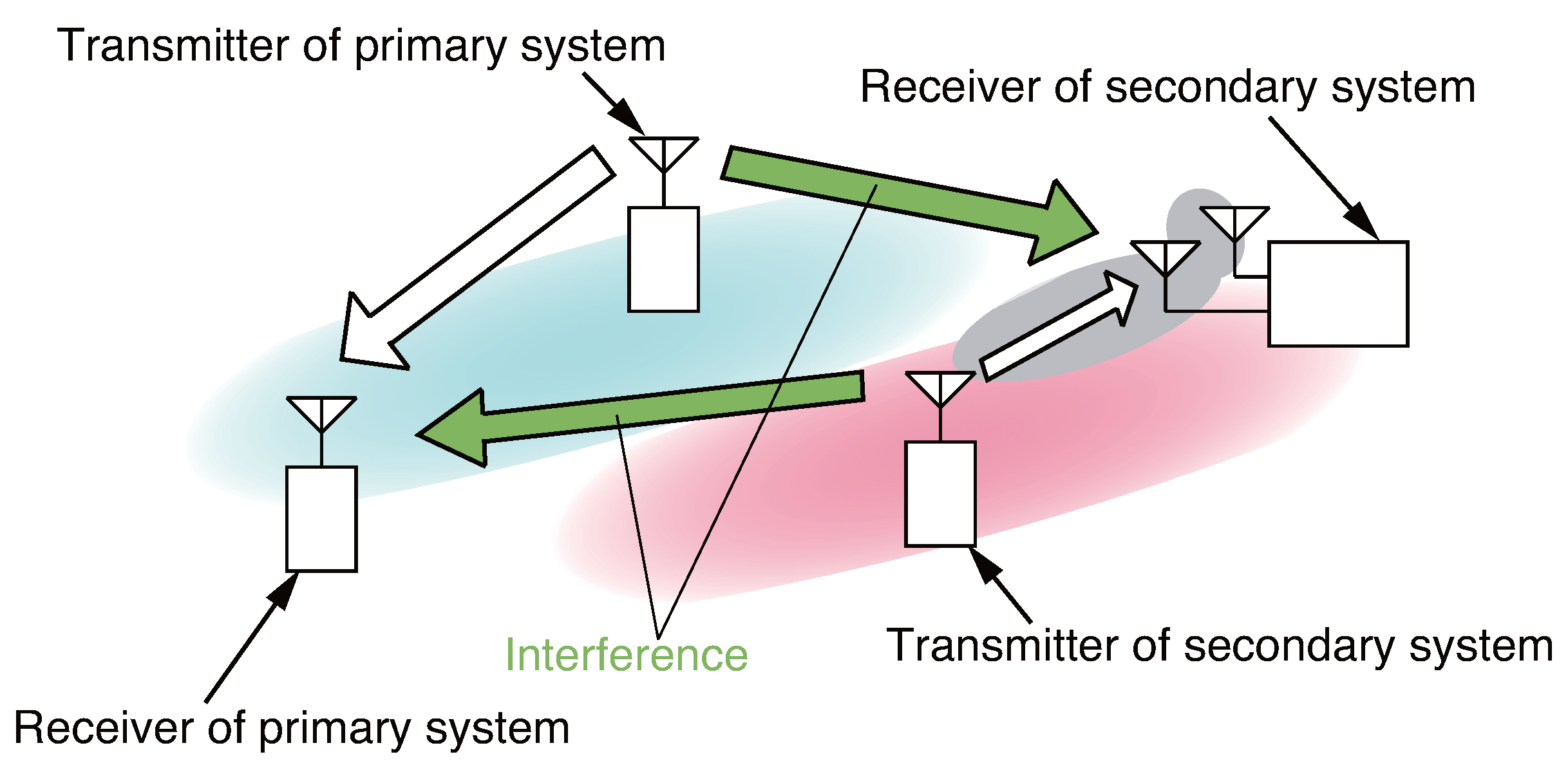
  • suppressing inter-system interference from the primary transmitter at the secondary receiver;
  • reducing inter-system interference to the primary receiver by the secondary transmitter;
  • both interference suppression/reduction must be realized in a blind manner.
Our original approach is to exploit the blind adaptive array (BAA) signal processing. It is quite effective in suppressing interference without inter-system CSI estimation. Constant modulus algorithm (CMA) [14,15] and power inversion (PI) [16,17] are well known BAA algorithms that do not require any a priori information such as a reference signal or direction of arrival. However, these algorithms are limited to some operational signal-to-interference power ratio (SIR) range at the input of receiver antenna elements. CMA cannot suppress the interference when SIR is smaller than 0 dB and PI cannot suppress it when SIR is greater than 0 dB. In other words, these algorithms face strong limits on their applicable region when the desired signal and the interference signal have almost the same power (SIR ≃ 0 dB). We then proposed a subcarrier transmission power assignment (STPA) [18,19], wherein the transmitter provides two levels of power density for each subcarrier: high and low levels. The receiver then applies CMA to high-level subcarriers and PI to low-level subcarriers so that these algorithms precisely work to suppress interference. It is regarded that the proposed STPA-BAA exploits power spectral densities as a priori information that can be implicitly shared between the transmitter and the receiver. The secondary receiver can successfully suppress the inter-system interference from the primary transmitter when SIR is equal to about 0 dB. Furthermore, STPA can improve an operational SIR for the primary system since low-level subcarriers of the secondary transmitter decreases the interference power to the primary receiver. Additionally, forward error correction (FEC) functions of the primary receiver also can compensate the strong interference influenced by high-level subcarriers. The fundamental effectiveness of the proposal was clarified through computer simulations under the scenario where two orthogonal frequency division multiplexing (OFDM) systems share the superposed spectrum [19]. Our approach can realize spectral efficiency improvement without any a priori information or sensing mechanisms. Its comprehensive comparison is summarized in Table 1. However, the practical performances of STPA-BAA appeared to be limited due to the hardware specifications, e.g., quantization or dynamic range of the transceiver. To elucidate this concern, the effectiveness of the STPA-BAA proposal was reported by fabricating and testing a prototype based on filter bank multicarrier transmission systems [20]. A major contribution of this paper is to expand its significance in terms of the detailed hardware implementation and results.
The rest of this paper is organized as follows. Section 2 describes the system model and our previously proposed STPA-BAA scheme. Section 3 and Section 4 present prototype specification and experiment results, respectively. Finally, Section 5 concludes the paper.

2. System Model and Proposed Scheme

2.1. System Model

Figure 1 shows the system model considered in this paper. Assuming a multicarrier transmission system, the secondary system with STPA-BAA is laid over the primary one on the superpose spectrum. It is noted that the primary system does not have the interference suppression function. Basically, in the cognitive radio network, the secondary system must not interfere with the primary system on the same frequency resources. Therefore, the secondary system should suppress interference from the primary transmitter as well as reduce interference to the primary receiver. SIR n and SIR total are defined as the SIR at the n-th ( 1 n N ) subcarrier and the total SIR among all subcarriers, respectively. Their relationship can be formulated as
SIR n = S n I n ,
SIR total = n = 1 N S n n = 1 N I n ,
where S n and I n stand for the desired and interference signal power at the n-th subcarrier, respectively. Let x l ( n , i ) denote the i-th symbol on the n-th subcarrier in the signal received by the l-th ( 1 l L ) antenna element. The L-by-1 received signal vector of the secondary system, X ( n , i ) , is defined as
X ( n , i ) = [ x 1 ( n , i ) x 2 ( n , i ) x L ( n , i ) , ] T ,
where ( . ) T denotes transposition. Received signal includes the desired signal for the secondary system and the inter-system interference signal from the primary one. The inter-system interference can be suppressed by BAA, which multiplies the received signal per subcarrier by a weight vector.

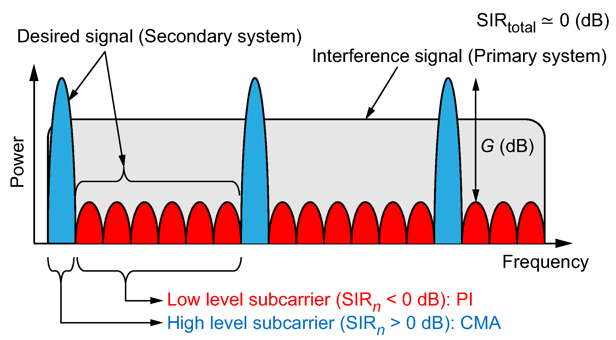
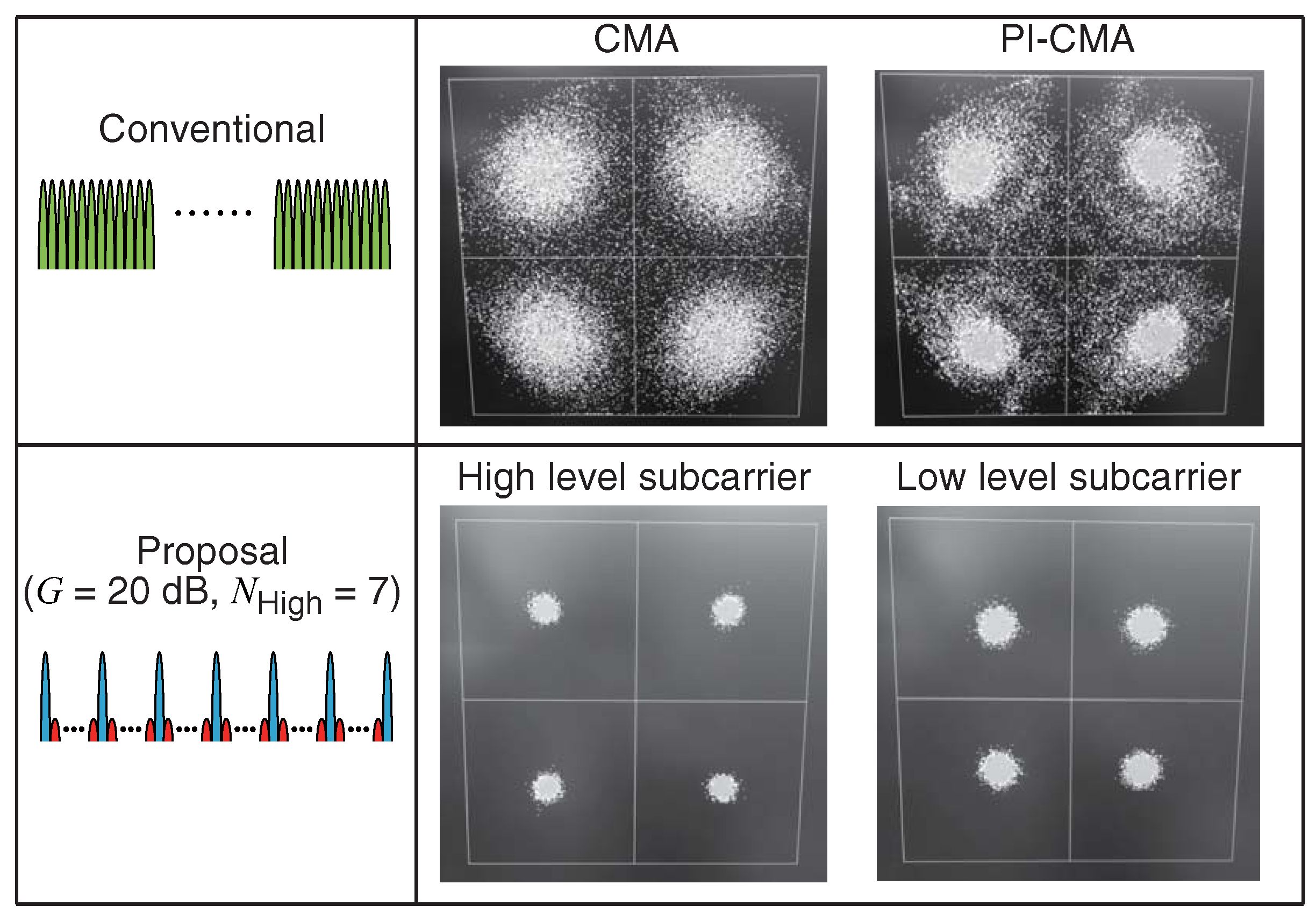
2.2. Proposal: Blind Adaptive Array with Subcarrier Transmission Power Assignment

Conventional BAA algorithms such as CMA and PI cannot suppress the interference enough when SIR total is equal to 0 dB [18]. Focusing on multicarrier systems, the secondary transmitter assigns different power densities to each subcarrier, that is, higher and lower level. At the secondary receiver, CMA and PI are selectively applied according to assigned power densities.
The concept of the proposed scheme is shown in Figure 2. G is defined as the power density difference between high and low-level subcarriers. N High is also defined as the number of high-level subcarriers. The pattern of one high-level subcarrier and multiple low-level subcarriers is assumed to be repeatedly arranged and total transmission power is controlled so as to equal that of the conventional one. When the interference from the primary system, transmitted at equal power spectral density, reaches the receiver of the secondary system, we can obtain the situation that SIR n of high-level subcarriers exceeds 0 dB while that of low-level subcarriers drops below 0 dB. The secondary system applies CMA to high-level subcarriers and PI to low-level subcarriers. This approach enables the interference suppression when SIR total is almost equal to 0 dB. Detailed algorithms of CMA and PI follow.

2.2.1. Constant Modulus Algorithm (CMA)

W CMA ( n ) defined as the L-by-1 CMA weight vector at the n-th subcarrier. CMA adapts the array output signal, y ( n , i ) , in order to yield a constant envelope by minimizing the following cost function:
Q ( W CMA ( n ) ) = E | y ( n , i ) | p σ p q = E W CMA H ( n ) X ( n , i ) p σ p q ,
where E [ . ] and ( . ) H denote ensemble mean and Hermitian transposition, respectively. σ is a constant envelope value and generally takes the value of one. p and q are positive integers, and take a value of one or two, respectively.
A number of algorithms were investigated to minimize Equation (4). We adopt least square CMA (LS-CMA) [15], which is known to exhibit superior convergence performance. CMA weight at the m-th iteration order, W CMA ( m ) ( n ) , is updated in the following manner:
W CMA ( m + 1 ) ( n ) = W CMA ( m ) ( n ) i = 1 S X ( n , i ) X H ( n , i ) 1 i = 1 S X ( n , i ) y * ( n , i ) δ * ( n , i ) = i = 1 S X ( n , i ) X H ( n , i ) 1 i = 1 S X ( n , i ) δ * ( n , i ) ,
δ ( n , i ) = σ | y ( n , i ) | y ( n , i ) ,
W CMA ( 0 ) ( n ) = [ 1 0 0 ] T ,
where p = 1 and q = 2 . m (=0, 1, 2, ...), S, and ( . ) * denote the index of CMA iteration, the index of sample, and complex conjugate, respectively. With the CMA, the desired signal must be captured at the initial array output. It indicates that the SIR n of the initial array output must be larger than 0 dB.

2.2.2. Power Inversion (PI)

PI has a property to invert the power ratio of the received signals by suppressing the signal having larger power. This leads to PI being able to effectively work when the power of the desired signal is smaller than that of the interference signal, i.e., SIR < 0 dB. The PI weight, W PI ( n ) , is calculated by autocorrelation matrix of the received signal, R x x ( n ) . They are defined as
W PI ( n ) = R x x 1 ( n ) C ,
R x x ( n ) = E X ( n , i ) X H ( n , i ) = 1 S i = 1 S X ( n , i ) X H ( n , i ) ,
C = [ 1 0 0 ] T ,
where C denotes a constraint vector.
As described, PI simply inverts the power ratio of incoming signals. Its interference suppression performance is limited in smaller absolute SIR value. W PI ( n ) can be used as the initial weight of CMA, W CMA ( 0 ) ( n ) , in Equation (5). It can enhance interference suppression performance of PI even when the power difference between desired and interference signals is small. Once the desired signal is captured by PI, residual interference signal can be further suppressed in the iteration process of CMA [19]. This approach can be classified as one variant of beamspace CMA (BSCMA) [21,22]. We define this scheme as PI-CMA.

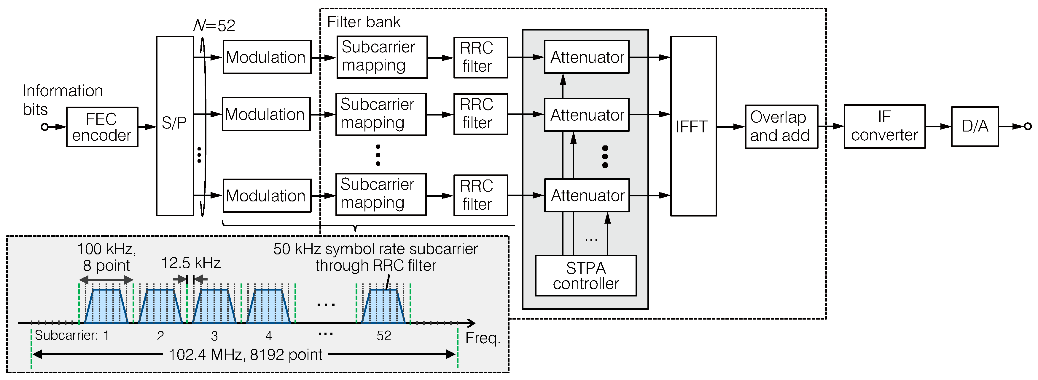
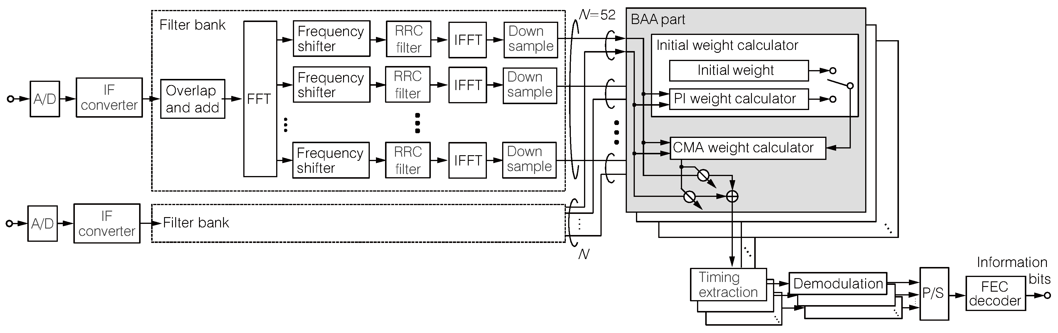
3. Prototype Specification

Figure 3 shows the external of the prototype. Table 2 lists the prototype specifications. It is composed of two field programmable gate array (FPGA) boards. Radio frequency (RF) part, modem part, STPA and BAA parts are implemented on one FPGA board while the FEC part is implemented on the other board. The transmitter and receiver are mounted on a single prototype. The receiver has two input ports capable of BAA signal processing. The prototype can also output the spectrum of the received signal after BAA processing as well as the constellations of the specific subcarrier.
We employed a fast Fourier transform (FFT) filter bank based multicarrier transmission system. In our first proposal in [19], FFT windowing and BAA per subcarrier were performed on the premise of ideal symbol timing extraction. In the presence of strong inter-system interference, the timing extraction may fail and hence FFT and BAA should be applied before that. In the FFT filter bank, we also utilized an overlapped FFT [23] so as to treat transmission/reception signals as continuous and we can obtain frequency domain signal in arbitrary timing at the receiver side. Filter bank multicarrier system can also keep orthogonality between subcarriers after the FFT time domain windowing function by providing guard bands. Although spectral efficiency is degraded compared to OFDM, the main contribution of this paper is to verify the effectiveness of the proposed STPA-BAA scheme. With this configuration, BAA is applied just after the FFT filter bank, and then followed by original reception process i.e., symbol timing extraction, demodulation, and FEC decoding.
Figure 4 shows a block diagram of the transmitter with STPA. The relationship between the system bandwidth, subcarrier bandwidth, and their arrangement is also depicted. The system bandwidth of the prototype is 102.4 MHz wherein central 5.2 MHz (=100 kHz × 52 subcarriers) are utilized for signal transmission. Multicarrier transmission signal is firstly generated in the frequency domain. The information bit sequence is encoded by a convolutional encoder. The encoded bits are converted to complex symbols according to the modulation level specified. The symbol rate of each subcarrier is 50 kHz wherein the minimum frequency resolution of the prototype system is 12.5 kHz; one symbol is represented by four sample points. Through a serial-to-parallel (S/P) converter, the symbols are mapped to each subcarrier with being shaped to the root raised cosine (RRC) frequency response. Roll-off factor of the RRC filter is 0.2 and subcarrier becomes 80 kHz bandwidth. Fifty-two subcarriers are arranged with 100 kHz spacing (i.e., eight points) without inter-carrier interference. In the STPA part, the variable digital attenuator reduces the power of low-level subcarriers to G dB. In the experiment, the total output power of all subcarriers are increased by an amplifier. Transmission signals for 52 subcarriers are superposed through an 8192 point inverse FFT (IFFT) and then the overlap-add method [24] is applied to obtain the time domain continuous waveform. The multicarrier signals are transmitted after being up-converted to the intermediate frequency (IF). Resolution of the digital-to-analog (D/A) converter is 16 bits.
Figure 5 then shows a block diagram of the receiver with BAA. Dynamic range of the receiver is 82 dB and resolution of the analog-to-digital (A/D) converter is 12 bits. Each receiver port extracts the signals received on each subcarrier through the overlapped FFT. Extracted subcarriers are individually RRC filtered in the frequency domain and converted to the time domain symbols via 8192 point IFFTs. Each symbol is downsampled to the 50 kHz symbol rate. It is also composed of four sample points. BAA weight for each subcarrier is calculated using the downsampled (but oversampled) symbols according to the pre-assigned subcarrier level (i.e., high or low), and then multiplied to the received signals. CMA (for high-level subcarriers) and PI-CMA (for low-level subcarriers) are implemented as BAA algorithms. After BAA is applied, symbol timing is detected using the unique word (UW) after carrier frequency recovery using a Costas loop [25]. It is performed per subcarrier and the prototype receiver utilizes a successfully estimated one. Finally, decimated symbols are demodulated and decoded to information bits as output after parallel-to-serial (P/S) conversion.

4. Laboratory Experiment

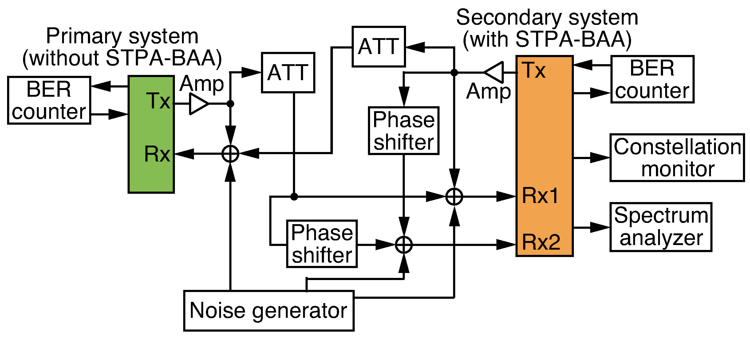
4.1. Experiment Setup

Figure 6 shows the wired setup of laboratory experiment and parameters are listed in Table 3. We assumed spectrum superposing scenarios between the primary system and the secondary system with STPA-BAA. Two prototype systems transmit multicarrier signals and interfere with each other. Each signal output from the transmitter is divided and superposed to another system through a variable attenuator (ATT) and a phase shifter. Interference signal level is controlled by the variable attenuator. The phase shifter provides the angle of arrival (AoA) difference between the primary and secondary receivers. AoA difference is set to 20 degrees where desired and interference signals are isolated enough and BAA can effectively suppress interference signal. Additive white Gaussian noise (AWGN) is also added; the signal-to-noise power ratio (SNR) is set to 30 dB. We assumed an interference limited scenario in order to clearly evaluate interference suppression performance of BAA. SNR and SIR are determined by measuring each signal power (desired signal, interference, and noise) just before the receiver input. This wired setup brings a frequency flat channel. Although the practical effectiveness of the STPA-BAA should be evaluated in multipath fading channel, this experiment first verifies its performance from the implementation viewpoint, the quantization levels or the receiver dynamic range.

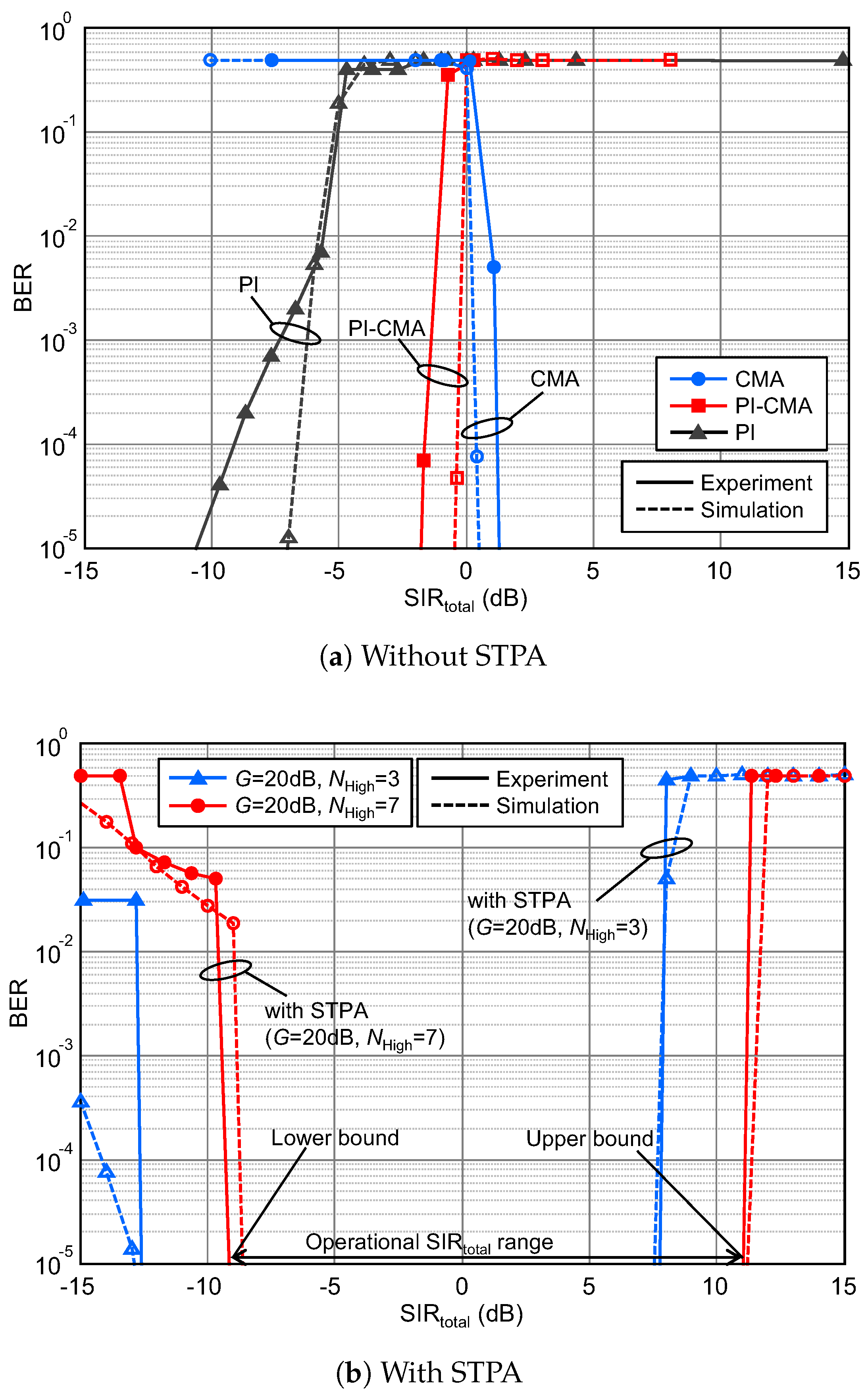
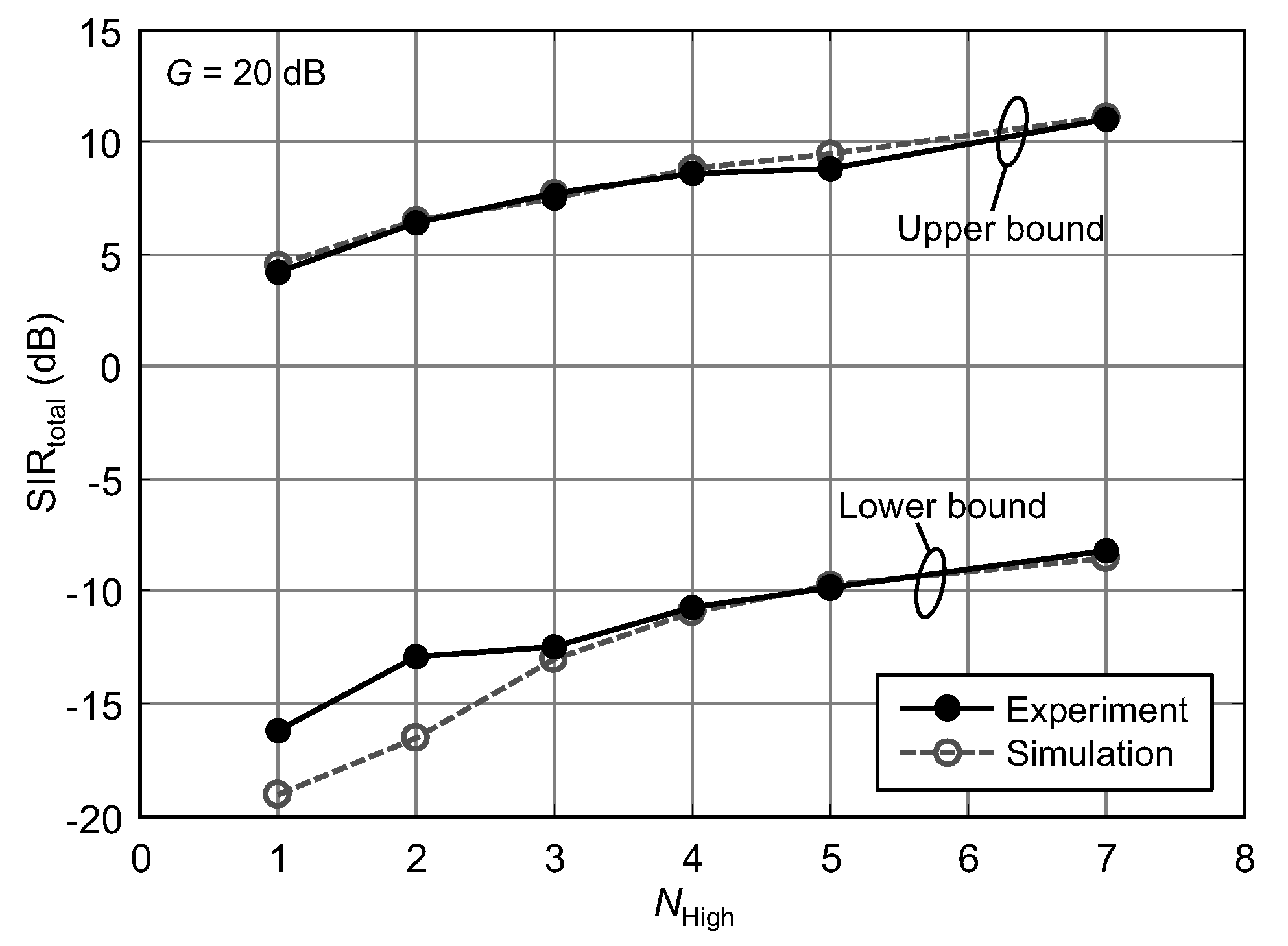
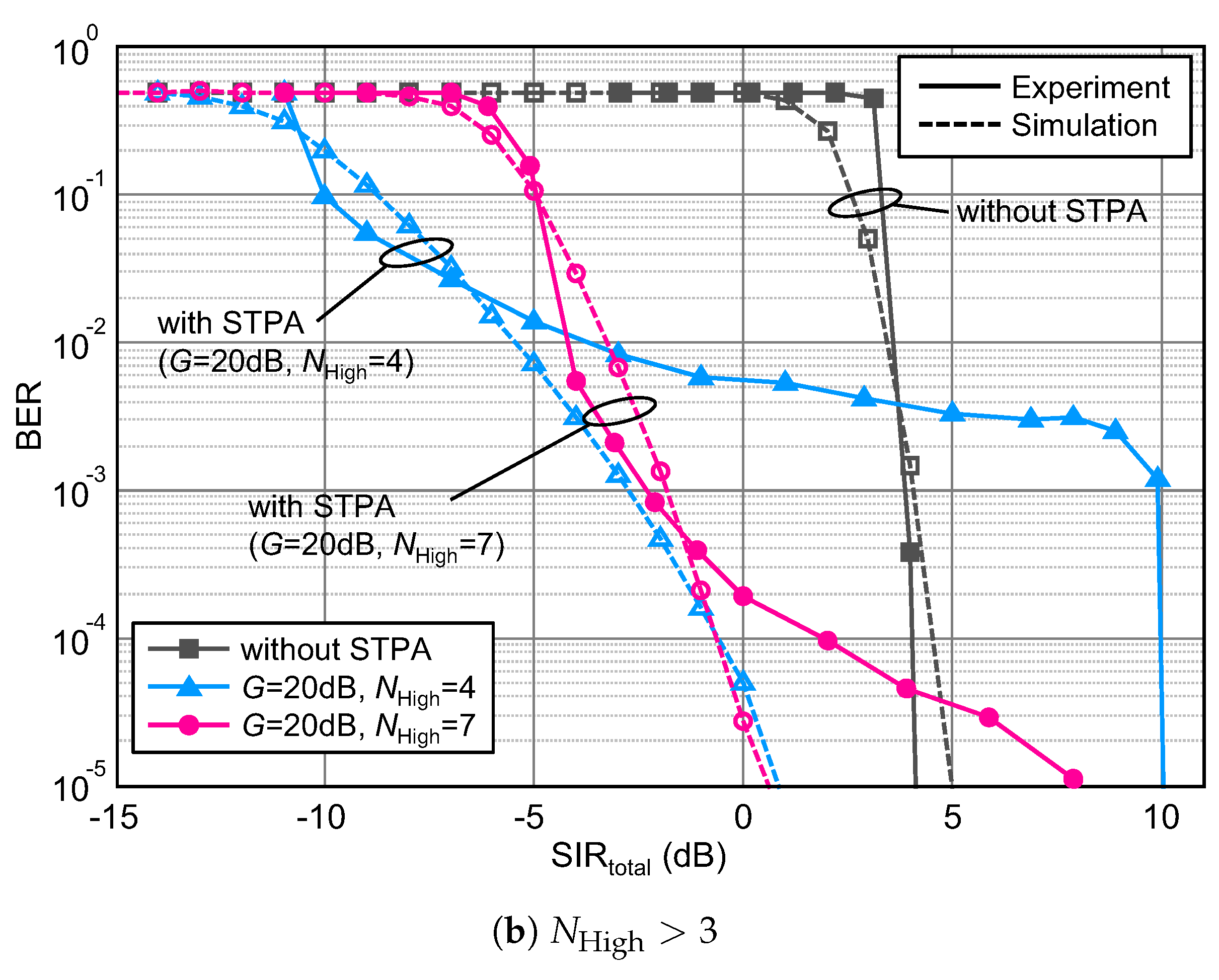
4.2. Experiment Results of the Secondary System

Figure 7 shows the in-phase and quadrature (IQ) constellation upon the application of BAA with/without STPA at SIR total = 0 dB, G = 20 dB, and N High = 7 . In BAA without STPA, the IQ constellation of the received signal is spread due to the unsuppressed interference; the resulting bit error rate (BER) was 0.5. BAA with STPA can effectively suppress the interference and thus the IQ constellation converged for both high and low-level subcarriers. Meanwhile, the amplitude of the IQ constellation at the low-level subcarriers was smaller than that at high-level subcarriers. It is obvious but enlarging the value of G degrades the reception performance of the low-level subcarriers.
Figure 8a shows the BER performance as a function of SIR total of the secondary system with a comparison to the simulation results. This figure shows the fundamental BER performance in the case that CMA, PI and PI-CMA are applied to all subcarriers without STPA. Simulation was conducted in the equivalent baseband domain assuming ideal conditions, without quantization nor oversampling. The SIR total offset of the experiment results to the simulated ones is within 2 dB except for the original PI. Since the BAA is applied to oversampled signals whose envelope is not constant, interference suppression ability is slightly weakened. In addition to that, discrepancy between two results of PI becomes larger than that of CMA and PI-CMA. It is because of excessive interference signal level to the receiver inputs. In the lower SIR total region, large power of the interference signal is input and the desired signal power is accordingly reduced so as not to exceed the dynamic range of the receiver inputs. It thus causes bit resolution shortage for the desired signal and the interference suppression performance of PI to deteriorate. Meanwhile, it can be confirmed that PI-CMA exhibits improved BER performance compared to the original PI. CMA utilizing PI as an initial weight can greatly enhance interference suppression performance. The legacy CMA and PI-CMA cannot suppress interference signal when SIR total is around 0 dB.
Figure 8b shows the BER performance of the secondary system with STPA-BAA with parameters G = 20 dB and N High = 3 and 7. The proposed scheme effectively works in the region around SIR total = 0 dB and improves the BER performance. Here, we define the operational region of the secondary system as the range to which SIR total holds the BER under 10 5 . In the case of Figure 8b, the upper and lower bounds that satisfy requirements are 11 and 9 dB, respectively; operational SIR total range is thus derived as 20 dB. Focusing on the upper bound, BER behavior of the experiment matches that of the simulation well and they exhibit almost the same upper bound SIR total value. In the higher SIR total region, interference signal level is slight, so that the sufficient dynamic range can be kept wherein BAAs suppress interference well. Although BER behaviors of the experiment and simulation results are different especially in the lower SIR total region, they almost coincide and satisfactory operational SIR total range can be ensured.
The operational SIR total range of the secondary system is revealed by the subcarrier power ratio, G, and the high-level subcarrier number, N High . Figure 9 shows the upper and lower bounds of the operational SIR total as a parameter of G when N High is set to 7. This experiment firstly measured the BER characteristics at the specified parameter of G and then obtained the upper and lower bounds as indicated in Figure 8b. The operational SIR total range can be seen as the difference between upper and lower bounds. For comparison, the computer simulation results are also plotted. Basically, operational SIR total range exhibits the same value as G because of the wired and flat fading channel. Experiment results show almost comparable performance to the simulation one. However, non-negligible deviation can be observed at G = 24 dB, and we confirmed that the prototype does not work at G = 26 dB. The conceivable reason is quantization resolution shortage of low-level subcarriers. STPA function of the prototype controls the power density of low-level subcarrier by digital attenuator, i.e., reducing the number of digits. Furthermore, 24 dB power attenuation is done by discarding the rightmost 8 bits; 10 log 10 ( 2 8 ) = 24.08 dB. At the receiver side, resolution for 24 dB attenuated symbols of low-level subcarrier is only 4 ( = 12 8 ) bits or less. It would degrade calculation accuracy of PI-CMA weight and thus interference cannot be well suppressed.
Figure 10 shows the upper and lower bounds of the operational SIR total as a function of N High . When N High decreases, the surplus power is reassigned to all subcarriers and hence the power density of overall subcarriers are increased. Accordingly, the power density of the interference signal to be suppressed by the secondary system is increased and the operational SIR total range is shifted to the lower side as N High is decreased. Here, operational SIR total in the lower bound by experiment shrinks at N High 2 compared to the simulation results. As mentioned above, it is due to the bit resolution shortage caused by ensuring the dynamic range of receiver inputs for larger interference signal power. This impact becomes more significant especially in low-level subcarriers. Increasing the number of quantization bits or enlarging dynamic range could avoid such degradations. These parameters should be optimized depending on the secondary system design.

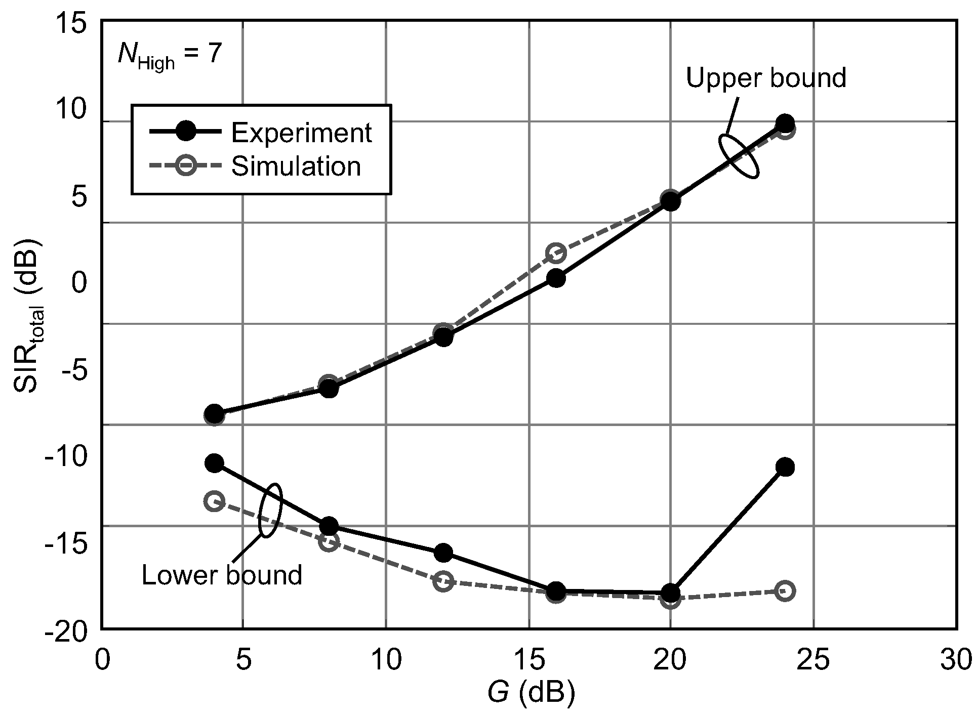
4.3. Experiment Results of the Primary System

Finally, we reveal the operational SIR total improvement of the primary system by STPA. Figure 11 shows the BER performances of experiment and simulation as a function of SIR at the primary system. The parameters of the secondary system are G = 20 and 24 dB, and N High = 1 , 3 , 4 , 7 . For comparison, BER performance is depicted when the secondary system does not perform STPA. When N High is 3 or lower (see Figure 11a), BER performance of the primary system can be improved. It should be noted that performance of the primary system depends on the symbol timing accuracy. Since the interference power within the bandwidth cannot be changed, the primary receiver should precisely detect the symbol timing in the interference dominant situation. As described in Section 3, the prototype receiver utilizes the symbol timing of a successfully estimated subcarrier. If inter-system interference from the secondary system is reduced on certain subcarriers, the primary receiver can extract symbol timing for demodulation and thus BER performance is improved. Meanwhile, when N High is larger than 3 (see Figure 11b), BER performance of the experiment becomes worse than that of the simulation. The large number of high-level subcarriers might affect over all BER characteristics of the primary receiver. Although FEC function is expected to compensate its undesired degradation, detailed mechanisms should be further investigated. SIR total improvements at BER = 10 5 in experiments are 2.5 dB at ( G , N High ) = ( 24 dB , 1 ) , 3.0 dB at ( G , N High ) = ( 20 dB , 3 ) and 7.0 dB at ( G , N High ) = ( 24 dB , 3 ) , respectively. Allowing degradation of interference suppression performance for the proposed scheme, larger value of G and lower value of N High can provide more effective interference reduction for the primary system. In addition, the experiment results match the computer simulation ones well except for the primary system with N High > 3 .
The above experiments verified a fundamental feasibility of the proposed spectrum superposing approach via STPA-BAA using a wired setup. For practical applicability, experiments should be conducted in outdoor environments where multipath components exist. Multipath fading might dynamically fluctuate levels of high and low subcarriers and it weakens interference suppression performance of BAAs. Although our simulative work showed the effectiveness of the proposal [19], more practical performance should be further investigated. In this case, OFDM is preferable since cyclic prefix (CP) can mitigate the inter-symbol interference (ISI) caused by the multipath effect. Here, challenges arise regarding how to extract an exact timing for FFT windowing in interference limited situations. FFT windowing should be performed before BAA processing per subcarrier; therefore, the timing extraction should be done in the presence of large inter-system interference, which causes the detection accuracy to deteriorate. Resolving the above issues, its overall effectiveness will be disclosed under practical application scenarios, e.g., LAA or LTE-U.

5. Conclusions

This paper experimentally verified the fundamental feasibility of our spectrum superposing scheme enabled by the proposed STPA-BAA. A prototype was fabricated and its performance in two multicarrier transmission systems was evaluated through a wired setup. The experiment demonstrated that STPA-BAA can suppress interference from the primary transmitter at SIR total of around 0 dB and can reduce interference to the primary receiver. Its practical applicable regions have been disclosed under some limitations in interference suppression ability due to the quantization or dynamic range of the transceiver. The most significant feature of the proposed scheme is that there is no need to modify the existing primary system. More detailed feasibility of the STPA-BAA scheme will be further investigated in more practical environments such as frequency selective fading channels.

Acknowledgments

The authors are sincerely grateful to Yutaka Sakuda, Michiaki Nagai, and Hiroshi Morooka of NTT Advanced Technology Corporation for their support on hardware implementation and prototype fabrication. The authors also give their sincere thanks to Takatoshi Sugiyama of Kogakuin University and Jun Mashino of NTT Docomo Inc. for their coordination of this work.

Author Contributions

H.S. and K.S. conducted experiments and analyzed the data; K.M. conceived the proposed scheme, provided simulation results and directed prototype fabrication; and H.S. and K.M. wrote the paper.

Conflicts of Interest

The authors declare no conflicts of interest.

Abbreviations

The following abbreviations are used in this manuscript:
Wi-FiWireless Fidelity
WiMAXWorld interoperability for Microwave Access
LTELong Term Evolution
OSAOpportunistic Spectrum Access
DSADunamic Spectrum Access
LTE-ULTE in Unlicensed spectrum
LAALicensed Assisted Access
LBTListen Before Talk
RTSRequest-to-Send
CTSClear-to-Send
OFDMOrthogonal Frequency Division Multiplexing
CPCyclic Prefix
ISIInter-Symbol Interference
FECForward Error Correction
MIMOMultiple-Input Multiple-Output
STPASubcarrier Transmission Power Assignment
BAABlind Adaptive Array
CMAConstant Modulus Algorithm
PIPower Inversion
FPGAField Programmable Gate Array
RFRadio Frequency
IFIntermediate Frequency
S/PSerial-to-Parallel
P/SParallel-to-Serial
D/ADigital-to-Analog
A/DAnalog-to-Digital
RRCRoot Raised Cosine
FFTFast Fourier Transform
IFFTInverse Fast Fourier Transform
UWUnique Word
AoAAngle of Arrival
ATTAttenuator
AWGNAdditive white Gaussian noise
QPSKQuadrature Phase Shift Keying
SNRSignal-to-Noise power Ratio
SIRSignal-to-Interference power Ratio
BERBit Error Rate

References

  1. Boccardi, F.; Heath, R.W.; Lozano, A.; Marzetta, T.L.; Popovski, P. Five disruptive technology directions for 5G. IEEE Commun. Mag. 2014, 52, 74–80. [Google Scholar] [CrossRef]
  2. Spencer, Q.H.; Swindlehurst, A.L.; Haardt, M. Zero-forcing methods for downlink spatial multiplexing in multiuser MIMO channels. IEEE Trans. Signal Process. 2004, 52, 461–471. [Google Scholar] [CrossRef]
  3. Haykin, S. Cognitive radio: Brain-empowered wireless communications. IEEE J. Sel. Areas Commun. 2005, 23, 201–220. [Google Scholar] [CrossRef]
  4. Zhao, Q. Spectrum Opportunity and Interference Constraint in Opportunistic Spectrum Access. In Proceedings of the 2007 IEEE International Conference on Acoustics, Speech and Signal Processing-ICASSP, Honolulu, HI, USA, 16–20 April 2007; Volume 3, pp. III-605–III-608. [Google Scholar]
  5. Zhao, Q.; Sadler, B.M. A Survey of Dynamic Spectrum Access. IEEE Signal Process. Mag. 2007, 24, 79–89. [Google Scholar] [CrossRef]
  6. Chang, G.Y.; Huang, J.F. A Fast Rendezvous Channel-Hopping Algorithm for Cognitive Radio Networks. IEEE Commun. Lett. 2013, 17, 1475–1478. [Google Scholar] [CrossRef]
  7. Takyu, O.; Yamakita, T.; Fujii, T.; Ohta, M.; Sasamori, F.; Handa, S. Optimization of Learning Time for Learning-Assisted Rendezvous Channel in Cognitive Radio System. IEICE Trans. Commun. 2015, 98, 360–369. [Google Scholar] [CrossRef]
  8. Valls, V.; Garcia-Saavedra, A.; Costa, X.; Leith, D.J. Maximizing LTE Capacity in Unlicensed Bands (LTE-U/LAA) While Fairly Coexisting With 802.11 WLANs. IEEE Commun. Lett. 2016, 20, 1219–1222. [Google Scholar] [CrossRef]
  9. Jian, Y.; Shih, C.F.; Krishnaswamy, B.; Sivakumar, R. Coexistence of Wi-Fi and LAA-LTE: Experimental evaluation, analysis and insights. In Proceedings of the 2015 IEEE International Conference on Communication Workshop (ICCW), London, UK, 8–12 June 2015; pp. 2325–2331. [Google Scholar]
  10. Song, Y.; Sung, K.W.; Han, Y. Coexistence of Wi-Fi and Cellular With Listen-Before-Talk in Unlicensed Spectrum. IEEE Commun. Lett. 2016, 20, 161–164. [Google Scholar] [CrossRef]
  11. Nishimori, K.; Taranto, R.D.; Yomo, H.; Popovski, P.; Takatori, Y.; Prasad, R.; Kubota, S. Spatial Opportunity for Cognitive Radio Systems with Heterogeneous Path Loss Conditions. In Proceedings of the 2007 IEEE 65th Vehicular Technology Conference-VTC2007-Spring, Dublin, Ireland, 22–25 April 2007; pp. 2631–2635. [Google Scholar]
  12. Park, J.; Park, Y.; Hwang, S.; Jeong, B.J. Low-Complexity GSVD-Based Beamforming and Power Allocation for a Cognitive Radio Network. IEICE Trans. Commun. 2012, 95, 3536–3544. [Google Scholar] [CrossRef]
  13. Sodagari, S. On effects of imperfect channel state information on null space based cognitive MIMO communication. In Proceedings of the 2015 International Conference on Computing, Networking and Communications (ICNC), Anaheim, CA, USA, 16–19 February 2015; pp. 438–444. [Google Scholar]
  14. Treichler, J.; Agee, B. A new approach to multipath correction of constant modulus signals. IEEE Trans. Acoust. Speech Signal Process. 1983, 31, 459–472. [Google Scholar] [CrossRef]
  15. Agee, B. The least-squares CMA: A new technique for rapid correction of constant modulus signals. In Proceedings of the IEEE International Conference on Acoustics, Speech, and Signal Processing (ICASSP), Tokyo, Japan, 7–11 April 1986; Volume 11, pp. 953–956. [Google Scholar]
  16. Compton, R.T. The Power-Inversion Adaptive Array: Concept and Performance. IEEE Trans. Aerosp. Electron. Syst. 1979, AES-15, 803–814. [Google Scholar] [CrossRef]
  17. Ukawa, T.; Fujimoto, M.; Hori, T. Optimal snapshot number of power inversion adaptive array in ITS communication environment. In Proceedings of the 2013 Asia-Pacific Microwave Conference Proceedings (APMC), Seoul, Korea, 5–8 November 2013; pp. 563–565. [Google Scholar]
  18. Maruta, K.; Mashino, J.; Sugiyama, T. Blind adaptive arrays with subcarrier transmission power assignment for spectrum superposing. In Proceedings of the 2014 Asia-Pacific Microwave Conference, Sendai, Japan, 4–7 November 2014; pp. 567–569. [Google Scholar]
  19. Maruta, K.; Mashino, J.; Sugiyama, T. Blind Interference Suppression Scheme by Eigenvector Beamspace CMA Adaptive Array with Subcarrier Transmission Power Assignment for Spectrum Superposing. IEICE Trans. Commun. 2015, 98, 1050–1057. [Google Scholar] [CrossRef]
  20. So, H.; Maruta, K.; Mashino, J.; Suzaki, K. Experimental Verification of Spectrum Superposing in Two Different Systems by Blind Adaptive Array with Subcarrier Transmission Power Assignment. In Proceedings of the 2016 IEEE 84th Vehicular Technology Conference (VTC-Fall), Montreal, QC, Canada, 18–21 September 2016; pp. 1–5. [Google Scholar]
  21. Chiba, I.; Chujo, W.; Fujise, M. Beam space constant modulus algorithm adaptive array antennas. In Proceedings of the 1993 Eighth International Conference on Antennas and Propagation, Edinburgh, UK, 30 March–2 April 1993; Volume 2, pp. 975–978. [Google Scholar]
  22. Nishimori, K.; Kikuma, N.; Inagaki, N. The Differential CMA Adaptive Array Antenna Using an Eigen-Beamspace System. IEICE Trans. Commun. 1995, 78, 1480–1488. [Google Scholar]
  23. Tanabe, M.; Umehira, M. Design and Performance of Overlap FFT Filter-Bank for Dynamic Spectrum Access Applications. IEICE Trans. Commun. 2012, 95, 1249–1255. [Google Scholar] [CrossRef]
  24. Oppenheim, A.V.; Schafer, R.W.; Buck, J.R. Discrete-Time Signal Processing, 2nd ed.; Prentice-Hall, Inc.: Upper Saddle River, NJ, USA, 1999. [Google Scholar]
  25. Costas, J. Synchronous Communications. IRE Trans. Commun. Syst. 1957, 5, 99–105. [Google Scholar] [CrossRef]
Figure 1. System model.
Electronics 07 00007 g001
Figure 2. Concept of blind adaptive array with subcarrier transmission power assignment (STPA-BAA). SIR: signal-to-interference power ratio; CMA: constant modulus algorithm; PI: power inversion.
Electronics 07 00007 g002
Figure 3. External of the prototype. RF: radio frequency; FEC: forward error correction.
Electronics 07 00007 g003
Figure 4. Transmitter employing STPA. S/P: serial-to-parallel; RRC: root raised cosine; IFFT: inverse fast Fourier transform; IF: intermediate frequency; D/A: digital-to-analog.
Electronics 07 00007 g004
Figure 5. Receiver employing BAA. A/D: analog-to-digital; P/S: parallel-to-serial.
Electronics 07 00007 g005
Figure 6. Experiment block diagram. BER: bit error rate; ATT: attenuator.
Electronics 07 00007 g006
Figure 7. In-phase and quadrature (IQ) constellation by BAA at SIR total = 0 dB (G = 20 dB and N High = 7).
Electronics 07 00007 g007
Figure 8. BER performance of the secondary system. (a) without STPA; (b) with STPA. STPA: subcarrier transmission power assignment.
Electronics 07 00007 g008
Figure 9. Operational SIR total range of the secondary system by subcarrier power ratio G ( N High = 7 ).
Electronics 07 00007 g009
Figure 10. Operational SIR total range of the secondary system by number of high level subcarrier N High ( G = 20 dB).
Electronics 07 00007 g010
Figure 11. BER performance of the primary system. (a) N High 3 ; (b) N High > 3 .
Electronics 07 00007 g011aElectronics 07 00007 g011b
Table 1. Comparisons in spectrum sharing/superposing approaches. DSA: dynamic spectrum access, CSI: channel state information.
DSANull-SteeringProposed
Spectral efficiency≤100%≥100%≥100%
Sharing domainTime/FrequencySpaceSpace
RequirementSpectrum usage of primary systemInter-system CSI
Table 2. Prototype specifications. FPGA: field programmable gate array; FFT: fast Fourier transform; IF: intermediate frequency; D/A: digital-to-analog; A/D: analog-to-digital; BAA: blind adaptive array; CMA: constant modulus algorithm; PI: power inversion.
ParametersValues
FPGAXilinx Vertex-4
Data bus bit-width8 bits
Clock frequency409.6 MHz
Sampling rate102.4 MHz
Number of FFT point8192
Frequency resolution12.5 kHz
Symbol rate per subcarrier50 kHz
Subcarrier spacing100 kHz
Number of subcarrier, N52
Pulse shaping filterRoot raised cosine, Roll-off factor: 0.2
IF frequency140 MHz
Resolution of D/A Converter16 bits
Resolution of A/D Converter12 bits
Receiver dynamic range82 dB
BAA algorithmCMA/PI/PI-CMA
Table 3. Experiment parameters.
ParametersValues
Number of Transmission antenna1 (Primary system)
1 (Secondary system)
Number of Reception antenna1 (Primary system)
2 (Secondary system)
Modulation schemeQPSK (quadrature phase shift keying)
FEC (forward error correction) schemeConvolutional code
Constraint length7
FEC Coding rate1/2
FEC DecoderViterbi
Bit interleaveNone
ChannelFrequency flat
SNR (signal-to-noise power ratio)30 dB
Angle of arrival difference 20
Number of sample for BAA, S512 (128 symbols)
CMA iteration number10
High/Low-level subcarrier power ratio, G4, 8, 12, 16, 20, 24 dB
Number of high-level subcarrier, N High 1, 2, 3, 4, 5, 7

