Article

Design of a T-Shaped Antenna Based on Characteristic Mode Manipulation for Metal-Framed Handset Application

1
College of Information Engineering, Shenzhen University, Shenzhen 518060, China
2
ATR National Key Laboratory of Defense Technology, College of Information Engineering, Shenzhen University, Shenzhen 518060, China
3
ZTE Corporation, No. 55 Keji Road South, Shenzhen 518057, China
*
Author to whom correspondence should be addressed.
Electronics 2018, 7(10), 209; https://doi.org/10.3390/electronics7100209
Submission received: 20 August 2018 / Revised: 10 September 2018 / Accepted: 16 September 2018 / Published: 20 September 2018

Abstract

:
Recently, metal-framed handset antennas have aroused much attention due to their fantastic appearance and superior robustness. In this paper, a T-shaped antenna suitable for integration with a USB connector is proposed for metal-framed handset application by utilizing the theory of characteristic modes (TCM). Five eigenmodes, one for the lower band and four for the higher band, were merged by a T-shaped metal frame, a feed point, and two shorting pins, as well as three radio frequency (RF) switches so as to broaden the antenna’s operating bandwidth. A prototype was fabricated in order to verify the design concept. Experimental results showed that the proposed antenna was able to cover bandwidths of 0.824–0.960 GHz (GSM band) and 1.710–2.690 GHz (DCS, PCS, UMTS, and LTE bands) with an acceptable radiation efficiency of up to 50% and satisfactory radiation patterns.

1. Introduction

In the past few years, with the development of mobile communication, metal-framed and metal shell handsets have been widely studied. The metal shell and metal frame of the handsets certainly greatly enhance the handsets’ appearance. However, they occupy a certain amount of space in the handsets as well, making it more challenging for the antenna design to achieve multi-band and high-efficiency characteristics. Hence, the main object of this study was to design a metal frame handset antenna without destroying the fantastic appearance and superior robustness of the handset structure.
Several handset antennas for mobile communication have been described in [1,2,3,4,5,6,7,8,9,10], covering bandwidths of 824–960 MHz and 1710–2690 MHz, and with desirable radiation efficiency. The antenna structure in [1] is a combination of a monopole antenna and a coupled ground line fabricated on an FR-4 substrate, covering the desired bandwidth with 3.82 dBi gain. A small-size reconfigurable loop antenna for mobile phone applications with a compact volume of 55 × 5 × 3 mm3 is proposed in [2]. To cover more operating bands with such a compact antenna, the reconfigurable technique is applied by inserting a radio frequency (RF) switch at the end of the proposed antenna to improve the bandwidth at the lower band. The antenna in [3] is an inverted-F antenna (IFA), which consists of four radiating branches. Each branch operates as an IFA and has a resonant length of a quarter-wavelength at the fundamental frequency.
The theory of characteristic modes (TCM) for antenna application has been studied recently to better understand the radiation principle [11,12,13,14,15,16,17,18,19,20,21,22]. TCM brings a clearer insight into an antenna’s physical behavior independent of the feeding arrangement by identifying the eigenmodes (characteristic modes) of the antenna structure. The handset antennas described in references [11,12,13] were analyzed using TCM to better adjust the antenna structure to make the antenna resonate at a certain frequency with high efficiency—up to 60%. Also, Sharma and Shanmugam employed a novel wideband modified Archimedean spiral antenna without a ground plane using TCM; hence, its radiation patterns are bidirectional as it radiates simultaneously in both directions [14].
In this paper, TCM was utilized to design a T-shaped antenna for metal-framed handset application. The first five eigenmodes were studied to reveal the resonant modes for both the lower and higher bands. With this knowledge, it was possible to easily adjust the structure more accurately by introducing a feed point and two shorting pins around the USB connector, making the antenna cover the bandwidths of GSM, DCS, PCS, UMTS, and LTE. Also, three RF switches were used to help the antenna achieve a multi-state resonation characteristic.
The contents of this paper are organized as follows. Section 2 discusses the structure of the proposed antenna. Subsequently, Section 3 uses TCM to analyze the antenna design. The techniques for merging and controlling multiple characteristic modes (CMs) are demonstrated with the help of simulation. Section 4 presents the fabrication of the antenna prototype and its measured results. Finally, Section 5 presents the conclusions of the work.

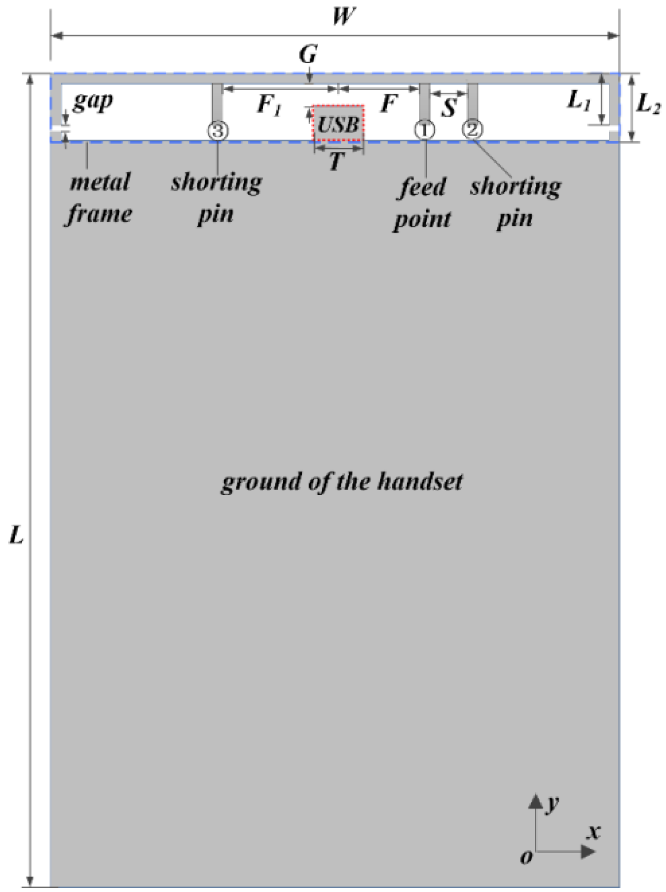
2. Antenna Configuration

Figure 1 presents the geometry of the proposed T-shaped antenna. The antenna was designed using the metal frame of the handset as the main radiator. A feed point (labeled ①) and two shorting pins (labeled ② and ③) were placed around the USB connector to excite the structure, working as Modes 1, 2, 3, 4, and 5, respectively. The USB connector with a width of T was located in the center of the metal frame. F and F1 represent the distance of points ① and ③ away from the USB connector, respectively. The space between point ① and ② is S. The working principles of the radiation characteristic will be discussed in detail in Section 3. The size of the handset was set to W × L with 2 mm gaps separating the metal frame and the ground plane. The gaps were filled with dielectric ( ε r = 2.2) to connect the metal-frame together. Therefore, the length of the metal frame could be considered as (L1 + L1 + W). The distance between the metal frame and the ground was L2. All these parameters are reasonable for practical smartphone antenna design and were simulated and optimized by the commercial electromagnetic software, CST Microwave Studio® 2015. The detailed parameters are tabulated in Table 1.

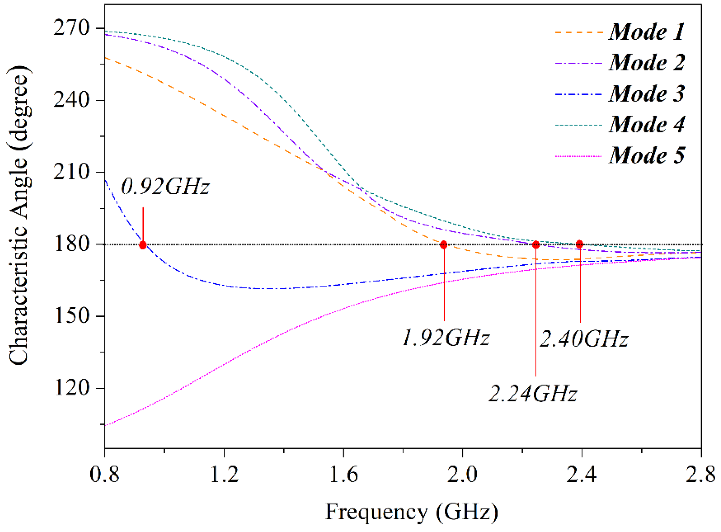
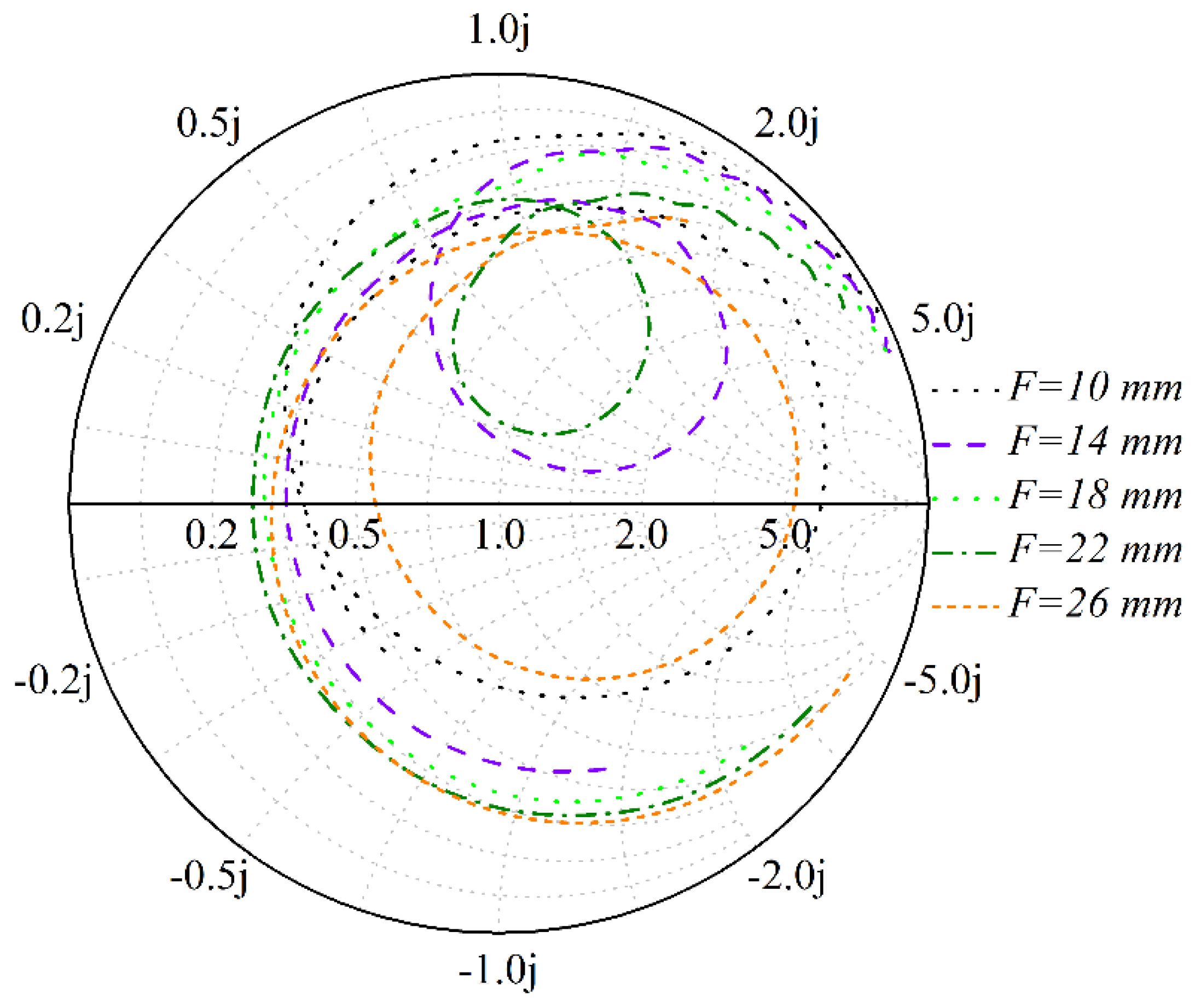
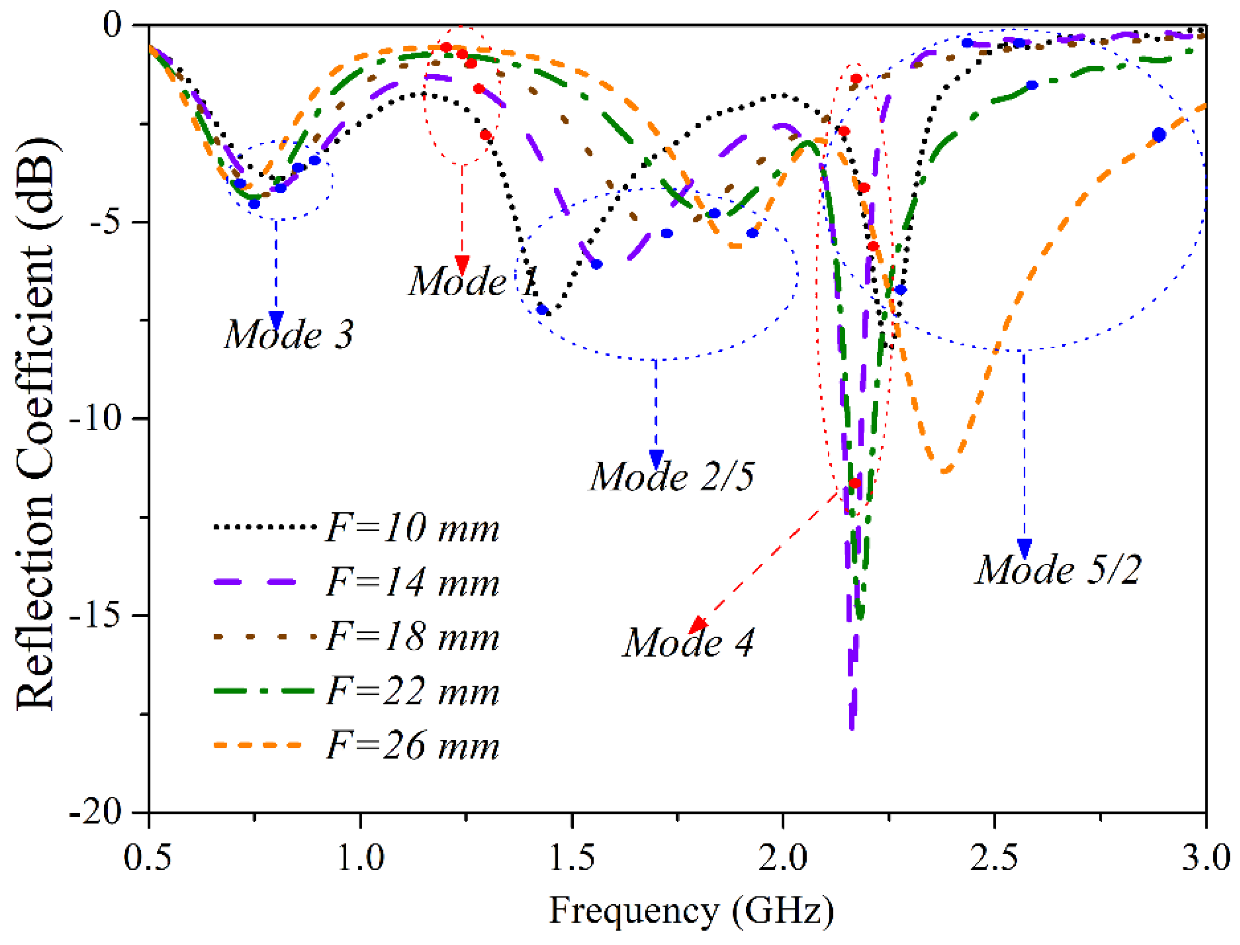
3. Working Principles of the Proposed Antenna

At the beginning of the analysis, the characteristic angles of the basic structure were tracked by simulation, with the shorting pins ② and ③ not taken into consideration. According to the TCM, the eigenmodes will be excited when the characteristic angles reach 180 degrees [19]. In Figure 2, one can observe that the characteristic angle of Mode 3 is equal to 180 degrees at the frequency of 0.92 GHz (lower band), while others reach 180 degrees from 1.92 GHz to 2.4 GHz (higher band). Considering the target bandwidths of the proposed antenna (0.824–0.960 GHz and 1.710–2.690 GHz), Mode 3 could be used to generate the lower operating band (0.824–0.960 GHz), and the other modes to achieve the higher bandwidth of 1.710–2.690 GHz. In order to better understand the modes shown in Figure 2, the characteristic current was simulated and is depicted in Figure 3. When concentrating on the current null point and the current peak point, Mode 3 can be seen as a 0.25 λ-mode of the longer arm of the metal frame, while Mode 2 is a 0.25 λ-mode of the shorter arm (λ is the wavelength in free space). Hence, moving the location of the feed point ① allowed to adjust the resonant frequency of the lower band. Mode 1 can be regarded as a 0.5 λ-mode of the whole arm. Mode 4 is a 0.75 λ-mode of the longer arm of the metal frame, while Mode 5 is a λ-mode of the whole metal frame. In addition, Mode 3 corresponded to the lower band, and the others to the higher band. After matching the eigenmodes and their characteristic currents, the effect of the parameters F, F1, and S could be better estimated.
The adoption of TCM in this work was able to give an insight into the antenna operating mechanism, offering a clear guideline for antenna performance improvement. According to the TCM analysis, the first five modes of the structure without shorting pins were demonstrated. The analysis could offer a better understanding about the corresponding part of the antenna which contributes to these modes. As Mode 1 could be considered the resonance generated from the whole arm of the metal frame, its resonant frequency could only be changed by adjusting the positions of the three points ①, ②, and ③. Also, if point ① was placed at the center of the metal frame, Modes 1, 2, and 3 would be located at around the same frequency. Therefore, it was possible to separate these modes by simply adjusting the feed point ①. In another case, if the feed point ① was placed at a quarter of the way along the frame width (W/4), Modes 2, 4, and 5 would be generated at around the same frequency. In order to excite a specific mode, the feed point could be placed at the position where its characteristic surface current reaches a maximum. Thus, Mode 5 could be easily excited by placing the feed point at a position around a quarter the width of the frame. Furthermore, in order to separate Modes 2, 4, and 5 and make the T-shaped antenna realize a multi-band characteristic, the value of F should be adjusted and optimized by simulation. According to the theory of a dipole antenna, the resonant frequency of Mode 1 can be made to be around 1.9 GHz, while that of Mode 3 can be made lower than 0.9 GHz by adjusting the value of F so as to cover the required bandwidth of GSM 850/900.
As mentioned above, the placement of the feed point can adjust the resonant frequencies of both the lower and the higher bands. Different values of F were simulated by CST Microwave Studio® and the impedance of different F values embodied in a Smith chart is presented in Figure 4. As the feed point moved away from the USB connector (and F increased), the knot in the Smith chart became smaller first, then larger again. When F = 18 mm, the knot disappeared, and this point was also where Mode 2 and Mode 5 reverse positions. When F < 18 mm, the sequence of the characteristic modes was Mode 3–Mode 1–Mode 2–Mode 4–Mode 5; if F > 18 mm, the sequence became Mode 3–Mode 1–Mode 5–Mode 4–Mode 2. The knot represents resonance at the higher band. A smaller distance away from the center of the Smith chart means a better resonance. Moreover, as the |S11| of different values of F illustrated in Figure 5, the value of F would affect all frequencies in both the lower and higher bands. The value of F was finally set at 14 mm, which rendered a better resonance in the higher band, as shown in Figure 6.
Another shorting pin ② could be inserted to make the lower band have a better resonance. Figure 6 is a comparison of |S11| with and without the shorting pin ②. One can see that the curve with the shorting pin ② has a better resonance phenomenon at the lower band, while its second resonance moves to a higher frequency, which is able to cover the bandwidth of 1710–2690 MHz. Figure 7 shows the Smith chart with and without the shorting pin ②. It can also be seen that the insertion of the shorting pin ② helped to squeeze the knot of the lower band without destroying the higher band resonance (Mode 4 and Mode 5).
Next, the shorting pin ③ was imported to adjust the resonant frequency of the higher band. The final states of the proposed antenna can be seen in Figure 8 and Figure 9. The two figures illustrate the final five |S11| and efficiency states of the proposed antenna, respectively. The final five states are described in Table 2. Three radio frequency (RF) switches were installed at points ①, ②, and ③. Each switch could be switched to different states, making the antenna work in five states. A 1 pF capacitor was introduced to the feed point in series so as to match the lower frequency in State 1 when the shorting pin ② was connected to the ground plane while the shorting pin ③ was disconnected. After adjusting the matching circle to a direct feed, State 2 was able to cover the band of 0.824–0.960 GHz together with State 1. The shorting pin ③ with different values of inductance would adjust the higher band resonance. When the shorting pin ③ was connected to the ground plane using an inductor of 3 nH, 6 nH, and 8 nH, States 3, 4, and 5, respectively, displayed resonance at the higher band. The shorting pin ③ should be 11.9 mm away from the USB connector, for this position is very suitable for parallel loading according to the characteristic currents shown in Figure 3. The bandwidth of |S11| (<−6 dB) and high efficiency (>50%) was great enough to cover the GSM, DCS, PCS, UMTS, and LTE bands.

4. Fabrication and Measurement

To validate the above analysis, a prototype was fabricated and measured. A photograph of the fabricated antenna is shown in Figure 10, and the experimental results of the prototype are shown in Figure 11 and Figure 12. The |S11| (|S11| < −6 dB) and efficiency (efficiency > 50%) bandwidth were wide enough to cover GSM, DCS, PCS, UMTS, and LTE bands.
The radiation pattern of the proposed antenna was also tested in an anechoic chamber. Figure 13 presents the simulated and measured results at the lower, middle, and higher bands of the structure. The patterns at the higher band split into more sidelobes because of the high-order mode generation. Also, the measured results and simulated results coincided with each other, showing the proposed antenna is an excellent candidate for a metal-framed handset antenna.

5. Conclusions

A novel and efficient method for designing a metal-framed handset antenna is proposed in this paper. TCM was adopted to better understand the working principle of the antenna by associating the radiation parts of the antenna structure with each corresponding resonant mode. A feed point and two shorting pins were inserted to help the antenna resonate at both the lower and higher bands. The feed point and shorting pins were properly placed by observing the characteristic currents of each mode. By using three RF switches, the antenna was made to work in five different states, insuring the antenna covered the bandwidths of 824–960 MHz and 1710–2690 MHz with an efficiency of 50% and |S11| < −6 dB. This design is very promising for industrial handset application.

Author Contributions

Conceptualization, C.-Z.H.; Supervision, J.-Z.W.; Writing—review & editing, G.-L.H. and T.Y.

Funding

This work was supported in part by National Natural Science Foundation of China (No. 61801300 and No. 61701320), State Key Laboratory of Millimeter Waves Grant (K201932), Shenzhen Science and Technology Grant (JCYJ20170818101347761) and New Teacher Natural Science Research Project of Shenzhen University (No. 2018078).

Conflicts of Interest

The authors declare no conflicts of interest.

References

  1. Chou, Y.J.; Lin, G.S.; Chen, J.F.; Chen, L.S.; Houng, M.P. Design of GSM/LTE multiband application for mobile phone antennas. Electron. Lett. 2015, 51, 1304–1306. [Google Scholar] [CrossRef]
  2. Wang, H.; Wang, Y.; Wu, J.; Chen, P.; Wu, Z.; Yang, G. Small-size reconfigurable loop antenna for mobile phone applications. IEEE Access 2016, 4, 5179–5186. [Google Scholar] [CrossRef]
  3. Sung, Y. Simple inverted-F antenna based on independent control of resonant frequency for LTE/wireless wide area network applications. IET Microw. Antennas Propag. 2014, 9, 553–560. [Google Scholar] [CrossRef]
  4. Kim, G.H.; Yun, T.Y. Small wideband monopole antenna with a distributed inductive strip for LTE/GSM/UMTS. IEEE Antennas Wirel. Propag. Lett. 2015, 14, 1677–1680. [Google Scholar] [CrossRef]
  5. Hsieh, H.W.; Lee, Y.C.; Tiong, K.K.; Sun, J.S. Design of a Multiband Antenna for Mobile Handset Operations. IEEE Antennas Wirel. Propag. Lett. 2009, 8, 200–203. [Google Scholar] [CrossRef]
  6. Park, S.J.; Shin, D.H.; Park, S.O. Low side-lobe substrate-integrated-waveguide antenna array using broadband unequal feeding network for millimeter-wave handset device. IEEE Trans. Antennas Propag. 2016, 64, 923–932. [Google Scholar] [CrossRef]
  7. Liu, H.; Li, R.; Pan, Y.; Quan, X.; Yang, L.; Zheng, L. A multi-broadband planar antenna for GSM/UMTS/LTE and WLAN/WiMAX handsets. IEEE Trans. Antennas Propag. 2014, 62, 2856–2860. [Google Scholar] [CrossRef]
  8. Yuan, B.; Cao, Y.; Wang, G. A miniaturized printed slot antenna for six-band operation of mobile handsets. IEEE Antennas Wirel. Propag. Lett. 2011, 10, 854–857. [Google Scholar] [CrossRef]
  9. Kearney, D.; John, M.; Ammann, M.J. Miniature ceramic dual-PIFA antenna to support band group 1 UWB functionality in mobile handset. IEEE Trans. Antennas Propag. 2011, 59, 336–339. [Google Scholar] [CrossRef]
  10. Cho, Y.J.; Hwang, S.H.; Park, S.O. A dual-band internal antenna with a parasitic patch for mobile handsets and the consideration of the handset case and battery. IEEE Antennas Wirel. Propag. Lett. 2005, 4, 429–432. [Google Scholar]
  11. Deng, C.; Feng, Z.; Hum, S.V. MIMO mobile handset antenna merging characteristic modes for increased bandwidth. IEEE Trans. Antennas Propag. 2016, 64, 2660–2667. [Google Scholar] [CrossRef]
  12. Szini, I.; Tatomirescu, A.; Pedersen, G.F. On small terminal MIMO antennas, harmonizing characteristic modes with ground plane geometry. IEEE Trans. Antennas Propag. 2015, 63, 1487–1497. [Google Scholar] [CrossRef]
  13. Miers, Z.; Li, H.; Lau, B.K. Design of bandwidth-enhanced and multiband MIMO antennas using characteristic modes. IEEE Antennas Wirel. Propag. Lett. 2013, 12, 1696–1699. [Google Scholar] [CrossRef]
  14. Sharma, S.K.; Shanmugam, B. Radiation pattern characteristics of a wideband novel modified archimedean spiral antenna array covering DCS/PCS/WLAN and LTE wireless communication bands. IEEE Antennas Wirel. Propag. Lett. 2011, 10, 1453–1456. [Google Scholar] [CrossRef]
  15. Young, M.W.; Bernhard, J.T. Characteristic mode investigation of a reactively loaded electrically small dipole antenna. In Proceedings of the 2015 9th European Conference on Antennas and Propagation (EuCAP), Lisbon, Portugal, 13–17 April 2015; pp. 1–2. [Google Scholar]
  16. Akiyama, N.; Michishita, N.; Morishita, H.; Satoh, H.; Koyanagi, Y. Characteristic mode analysis for small handset antenna. In Proceedings of the 2017 International Symposium on Antennas and Propagation (ISAP), Phuket, Thailand, 30 October–2 November 2017; pp. 1–2. [Google Scholar]
  17. Yang, X.; Liu, Y.; Gong, S. Design of a wideband omnidirectional antenna with characteristic mode analysis. IEEE Antennas Wirel. Propag. Lett. 2018, 17, 993–997. [Google Scholar] [CrossRef]
  18. Wen, D.; Hao, Y.; Wang, H.; Zhou, H. Design of a wideband antenna with stable omnidirectional radiation pattern using the theory of characteristic modes. IEEE Trans. Antennas Propag. 2017, 65, 2671–2676. [Google Scholar] [CrossRef]
  19. Harrington, R.; Mautz, J. Computation of characteristic modes for conducting bodies. IEEE Trans. Antennas Propag. 1971, 19, 629–639. [Google Scholar] [CrossRef]
  20. Mosallaei, H.; Sarabandi, K. Antenna miniaturization and bandwidth enhancement using a reactive impedance substrate. IEEE Trans. Antennas Propag. 2004, 52, 2403–2414. [Google Scholar] [CrossRef]
  21. Li, L.W.; Li, Y.N.; Yeo, T.S.; Mosig, J.R.; Martin, O.J. A broadband and high-gain metamaterial microstrip antenna. Appl. Phys. Lett. 2010, 96, 164101. [Google Scholar] [CrossRef] [Green Version]
  22. Yao, J.; Tchafa, F.M.; Jain, A.; Tjuatja, S.; Huang, H. Far-field interrogation of microstrip patch antenna for temperature sensing without electronics. IEEE Sens. J. 2016, 16, 7053–7060. [Google Scholar] [CrossRef]
Figure 1. Proposed T-shaped antenna configuration with a feed point, two shorting pins and a USB connector.
Electronics 07 00209 g001
Figure 2. Characteristic angles of the first five modes of the structure: Mode 3 at 0.92 GHz, Mode 1 at 1.92 GHz, Mode 2 at 2.24 GHz, and Mode 4 at 2.4 GHz.
Electronics 07 00209 g002
Figure 3. Surface current of the first five modes of the structure: (a) Mode 3; (b) Mode 1; (c) Mode 2; (d) Mode 4; (e) Mode 5; (f) all modes.
Electronics 07 00209 g003
Figure 4. Smith chart showing different values of F: 10 mm, 14 mm, 18 mm, 22 mm, and 26 mm.
Electronics 07 00209 g004
Figure 5. |S11| with different values of F: 10 mm, 14 mm, 18 mm, 22 mm, and 26 mm.
Electronics 07 00209 g005
Figure 6. |S11| with and without the shorting pin ② for the proposed T-shaped antenna.
Electronics 07 00209 g006
Figure 7. Smith chart with and without the shorting pin ② for the proposed T-shaped antenna.
Electronics 07 00209 g007
Figure 8. Five |S11| states of the proposed T-shaped antenna: State 2 for lower bands and the other four states for mid and high bands.
Electronics 07 00209 g008
Figure 9. Five efficiency states of the proposed antenna: State 2 for lower bands and the other four states for mid and high bands.
Electronics 07 00209 g009
Figure 10. Photograph of the prototype.
Electronics 07 00209 g010
Figure 11. Measured result of five |S11|: State 2 for lower bands and the other four states for mid and high bands.
Electronics 07 00209 g011
Figure 12. Measured results of efficiency: State 2 for lower bands and other the four states for mid and high bands.
Electronics 07 00209 g012
Figure 13. Simulated and measured radiation patterns of the proposed antenna: (a) at 0.840 GHz; (b) at 1.900 GHz; (c) at 2.500 GHz.
Electronics 07 00209 g013
Table 1. Parameters of the proposed antenna
ParameterValue (mm)ParameterValue (mm)
W80L140
L16L29
T6S3.2
F14F111.9
G2.2
Table 2. Five states of the proposed antenna.
StateFeed Point ①Shorting Pin ②Shorting Pin ③
11 pF in seriesSwitch onSwitch off
2Switch onSwitch onSwitch off
3Switch onSwitch off3 nH
4Switch onSwitch on6 nH
5Switch onSwitch on8 nH

