A New Method of the Pattern Storage and Recognition in Oscillatory Neural Networks Based on Resistive Switches


Institute of Physics and Technology, Petrozavodsk State University, 31 Lenina str., Petrozavodsk 185910, Russia
*
Author to whom correspondence should be addressed.
Electronics 2018, 7(10), 266; https://doi.org/10.3390/electronics7100266
Submission received: 10 September 2018
/
Revised: 16 October 2018
/
Accepted: 18 October 2018
/
Published: 22 October 2018
(This article belongs to the Special Issue Nanoelectronic Materials, Devices and Modeling)
Abstract
:Development of neuromorphic systems based on new nanoelectronics materials and devices is of immediate interest for solving the problems of cognitive technology and cybernetics. Computational modeling of two- and three-oscillator schemes with thermally coupled VO2-switches is used to demonstrate a novel method of pattern storage and recognition in an impulse oscillator neural network (ONN), based on the high-order synchronization effect. The method allows storage of many patterns, and their number depends on the number of synchronous states Ns. The modeling demonstrates attainment of Ns of several orders both for a three-oscillator scheme Ns ~ 650 and for a two-oscillator scheme Ns ~ 260. A number of regularities are obtained, in particular, an optimal strength of oscillator coupling is revealed when Ns has a maximum. Algorithms of vector storage, network training, and test vector recognition are suggested, where the parameter of synchronization effectiveness is used as a degree of match. It is shown that, to reduce the ambiguity of recognition, the number coordinated in each vector should be at least one unit less than the number of oscillators. The demonstrated results are of a general character, and they may be applied in ONNs with various mechanisms and oscillator coupling topology.
1. Introduction
Usage of artificial neural networks [1] for information processing allows mastering the problems that arise when traditional computation schemes are applied in such areas as pattern and speech recognition [2], and data computation and encoding [3]. Therefore, the important research trends include studying the modes of oscillator neural network (ONN) operation and training, implementation of associative memory modes based, for example, on weakly coupled phase oscillators (Kuramoto model) [4] or impulse oscillators [5,6]. The effect of synchronization plays a crucial role in ONN operation, and is often used as a marker of ONN action, for example, in pattern recognition event.
There is a class of ONNs based on relaxation oscillators that generate subsequent pulses (spikes). These oscillators, in turn, are composed of electronic components with resistive switching effect, for example, VO2-switches [7,8], 1T-TaS2 charge density wave devices [9,10,11], thyristors [12], tunneling diodes [13], resistive memory elements [14], spin-torque nano-oscillators [15]. Such ONNs appear to be interesting because of hardware solution simplicity, as well as compactness and energy efficiency of the developed micro- and nanoelectronic self-oscillators. VO2-based oscillators, as the elements of ONNs, have been chosen because they ensure rapid electric switching (~10 ns) [16], manufacturability with high degree of nanoscaling [17] and, above all, because of the pronounced effect of thermal coupling that simplifies ONN assembly and circuit engineering of galvanically isolated oscillators. Consequently, VO2-oscillators started being used as the prototypes of neuro-oscillators for cognitive technology [8,16,18].
In ONNs, the system demonstrates frequency and phase synchronization [19,20,21,22] and, also, synchronization of high order [17,23] at certain control parameters, such as parameters of an oscillator scheme or coupling strengths between the oscillators. The method proposed, here, of pattern storage and recognition, is based on the effect of high-order synchronization, that has been experimentally demonstrated through thermally coupled VO2-oscillators [17]. In many studies [22,24,25], patterns to be stored are expressed through a set of vectors. Vector coordinates contain information about the pattern and unambiguously associate it with one of possible variants. For instance, the vector of the object’s color in RGB coordinates (white color—RGB (255,255,255)) may be used as a 3-dimension vector. There are some methods of vector storage based on oscillator elements’ synchronization in ONNs, and one of them is presented in paper [20]. To store E vector, a phase-shift keying method of a test vector T is specified by weight matrix setting; at the second stage, the weights are sharply changed to the initial values (corresponding to the stored vectors), and the system arrives at one of the stable combinations of phase shift E. However, this phase method has the following drawbacks: N2 couplings with tunable weights and a two-stage procedure of pattern recognition.
A second known method of vector storage is a frequency-shift keying method of encoding, based on synchronized frequency shift [22]. According to this method, vector E is stored through oscillator frequency shifts against the central frequency of oscillator array F0 synchronization (on the first harmonic) per the values corresponding to the vector coordinates E = (δω1, δω2, …, δωN). Recognition of test vector T occurs at the reverse shift of frequencies and, in the case when the vectors coincide T ≈ E, the synchronization, indicating the fact of pattern recognition, takes place. This method allows usage of an oscillator star configuration and only N couplings, however, the disadvantage of this method is that just one vector is stored.
The present work suggests a conceptually new method of vector (pattern) storage and recognition when an array of coupled oscillators enables storage of a multitude of vectors. This result is achieved due to the effect of high-order synchronization in our ONN, that has many oscillator synchronous states and, also, because of specific algorithm of the network training and identification of the degree of match for the tested objects.
2. Materials and Methods
2.1. General Principle
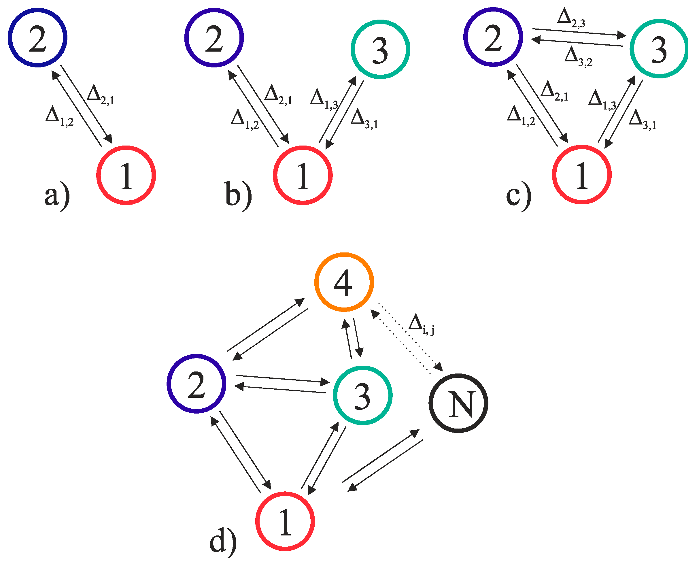
An oscillator neural network is a system of N coupled oscillators, which may be connected via electric (by resistors and capacitors) [7,26], thermal [17], and optic [27] couplings, depending on the physical mechanism of oscillator interaction. In the general case, there is a matrix of coupling strengths Δi,j (weights), where i, j are the numbers of interacting oscillators, and Δi,j denotes the value of the i-th oscillator effect on the j-th one. Oscillator networks may form various topologies: fully connected—all-to-all; and not fully connected—bus, star, and ring. Figure 1a–c show examples of two and three oscillators connections using topologies “star”, “all-to-all”, and an example of N oscillator connections using a mixed topology (Figure 1d).
It is known [17,23] that oscillators in a network may undergo the effect of synchronization and, besides synchronization on the first harmonic, synchronous modes of high order may be observed if the signal spectra possess several harmonics. To evaluate synchronization, in this work, we use a family of metrics that consists of two parameters (SHR is the value of high order synchronization and η is the effectiveness of synchronization). A detailed method of its determination is given in Section 2.3 and in [17].
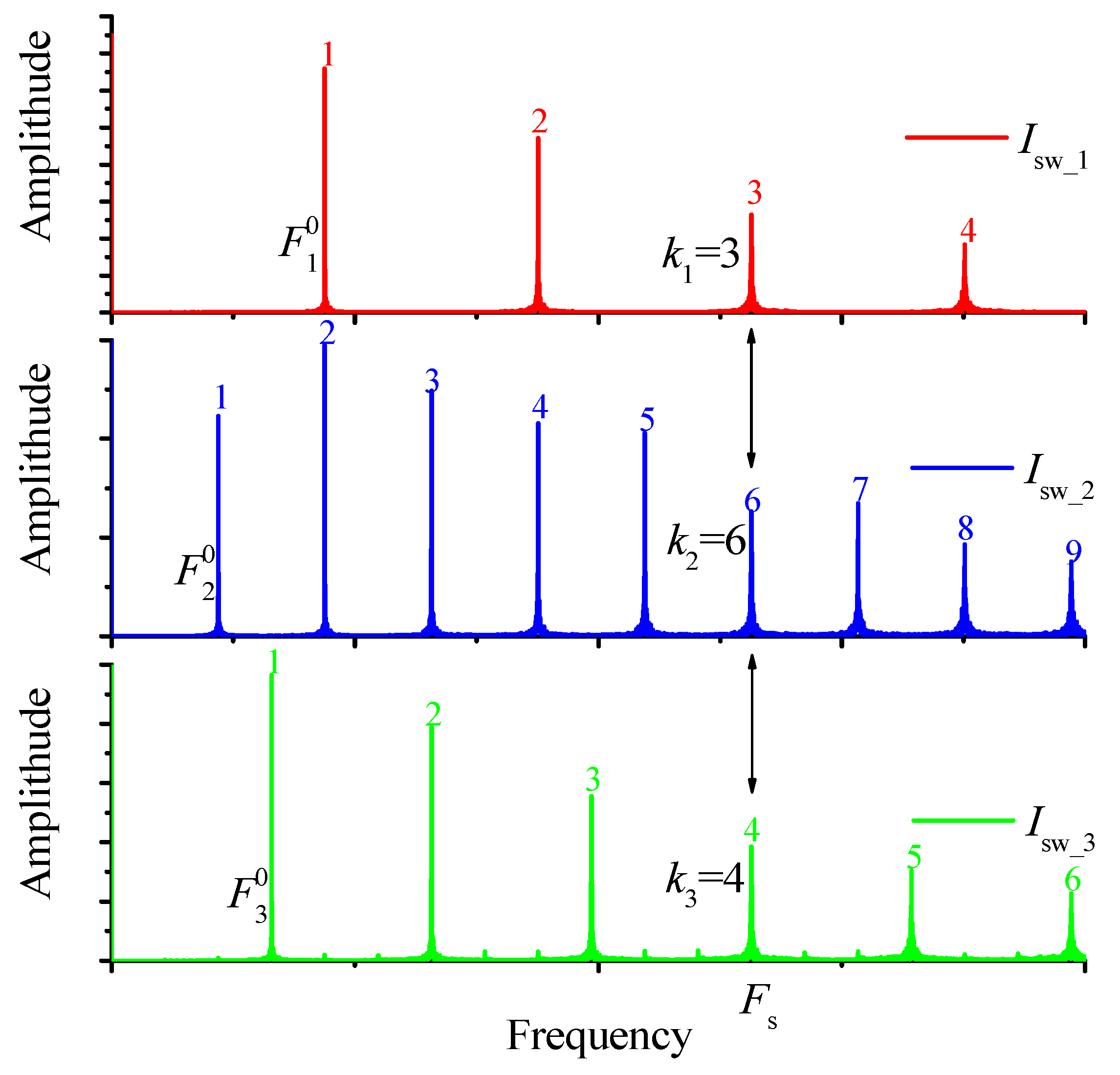
In the general case, high-order synchronization is determined by the ratio SHR = k1:k2:k3:..:kN, where kN is a harmonic order of N-th oscillator at the common frequency of the network synchronization Fs, (SHR—subharmonic ratio). As an example, Figure 2 shows spectra of three electric oscillators that have synchronization of the order SHR = k1:k2:k3 = 3:6:4. The following rule should be noted: if all paired oscillators have different synchronization frequencies, there is always a common synchronization frequency Fs for the whole system (all pairs), and the network synchronous state will also be determined by the ratio SHR = k1:k2:k3:..:kN at frequency Fs (see Section 2.3).
In addition to SHR, there is also a parameter of synchronization effectiveness η, that shows what share of oscillations of the whole time signal is synchronized. This parameter is expressed in percentages (see Section 2.3). If, at any point, η is less than the threshold value ηth, then SHR is absent, and the signal is considered conventionally non-synchronized.
Transition from one synchronous state into another is possible when the oscillator network control parameters are varied. For example, in electric oscillators, the main parameters may be oscillator feed currents Ip, their variation causes changes of the basic oscillation frequency F0. Nevertheless, in some cases, transition between states may be achieved by variation of coupling forces or noise intensity.
The range of control parameters variation, where synchronization does not change its state, is called a synchronization area. There is a whole family of synchronization areas that are called Arnold’s tongues (for the case of two oscillators). A schematic example of synchronization areas for a three-oscillator scheme is shown in Figure 3a. Here, the control parameters are oscillator feed currents. Each area has its own value of SHR. Besides, each area has its own distribution of the synchronization effectiveness value within ηth < η < 100%, with a peaked curve.
The number of possible variants of synchronous states (synchronization areas), where the system may exist when the basic control parameters are varied, is denoted as Ns. The value of Ns depends on many parameters: the oscillator number N, the range of control parameters and their number, network topology, strength of coupling between oscillators, noise level in the system and on the threshold value of synchronization effectiveness ηth. We will cover the issue in detail later, nevertheless, we have shown in [28], that for a two-oscillator network, Ns has a maximum at certain values of coupling strengths between oscillators, and decreases when the system noise amplitude increases. When the coupling strength grows considerably, the value Ns decreases because of the nearby synchronization areas’ integration.
Vectors E1, E2, ..., ENS, that connect the origin of coordinates with the points of synchronization effectiveness maximum η, can be associated with the synchronization areas. Thus, the system stores Ns of vectors, and the dimensionality of the stored vectors M is determined by the number of chosen control parameters. The coordinates determine the shift of oscillators’ control parameters, for example, currents E = (δIp1(1), δIp2(2), …, δIpN(M)), against the origin of coordinates.
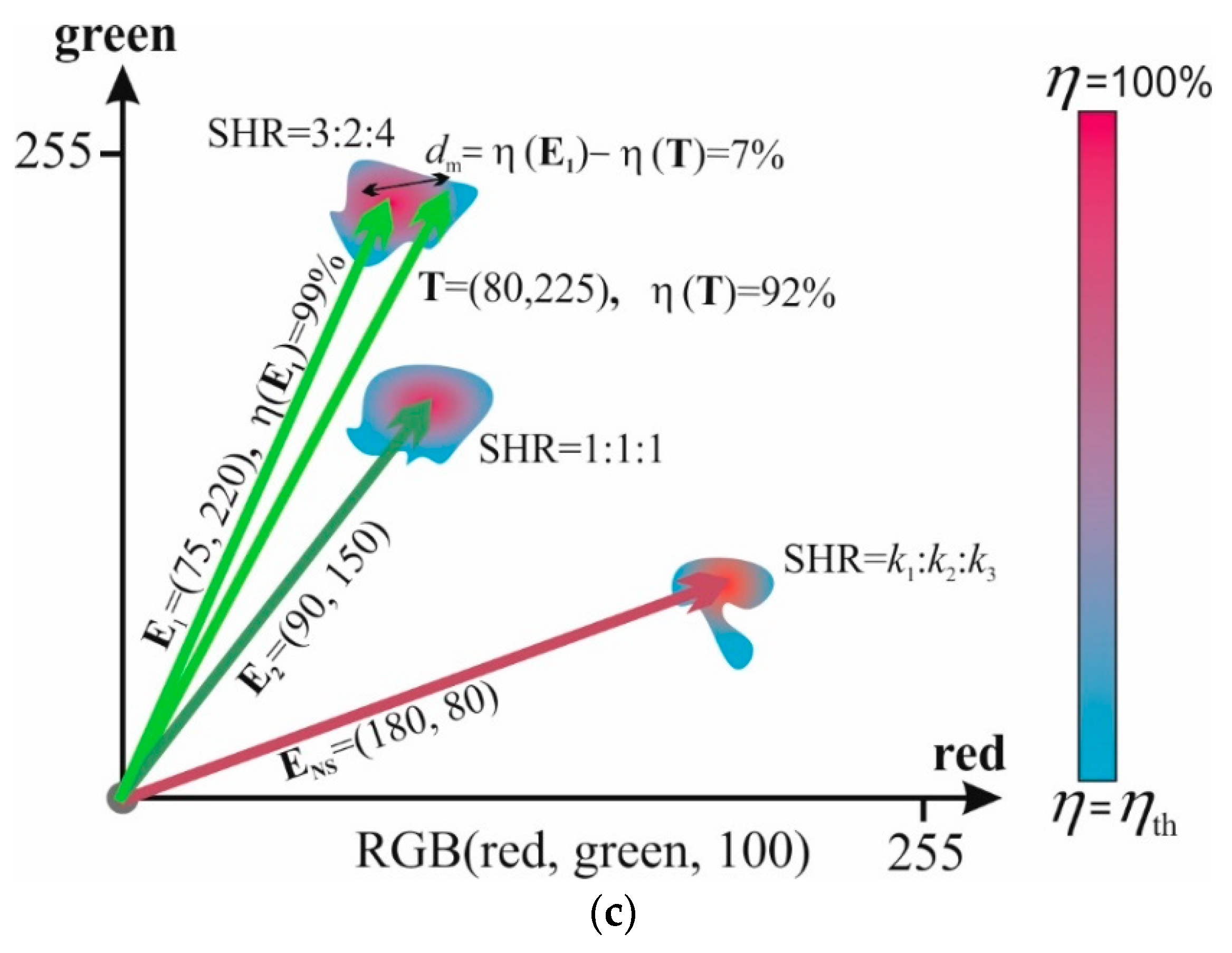
As we have mentioned in the introduction section, the patterns to be stored are usually expressed through a set of vectors. Vector coordinates contain information about the pattern and unambiguously associate it with one of possible variants. For example, Figure 3c shows storage of the object’s colors in the RGB format (red, green, blue) through the coordinates of vectors E, whose values give the information about the intensity of red and green colors E = (red, green), and parameter blue is fixed as blue = 100. This example, in Figure 3c, shows the intensities of RGB components on the axes that can be linearly transformed into the values of the oscillator currents and vice versa.
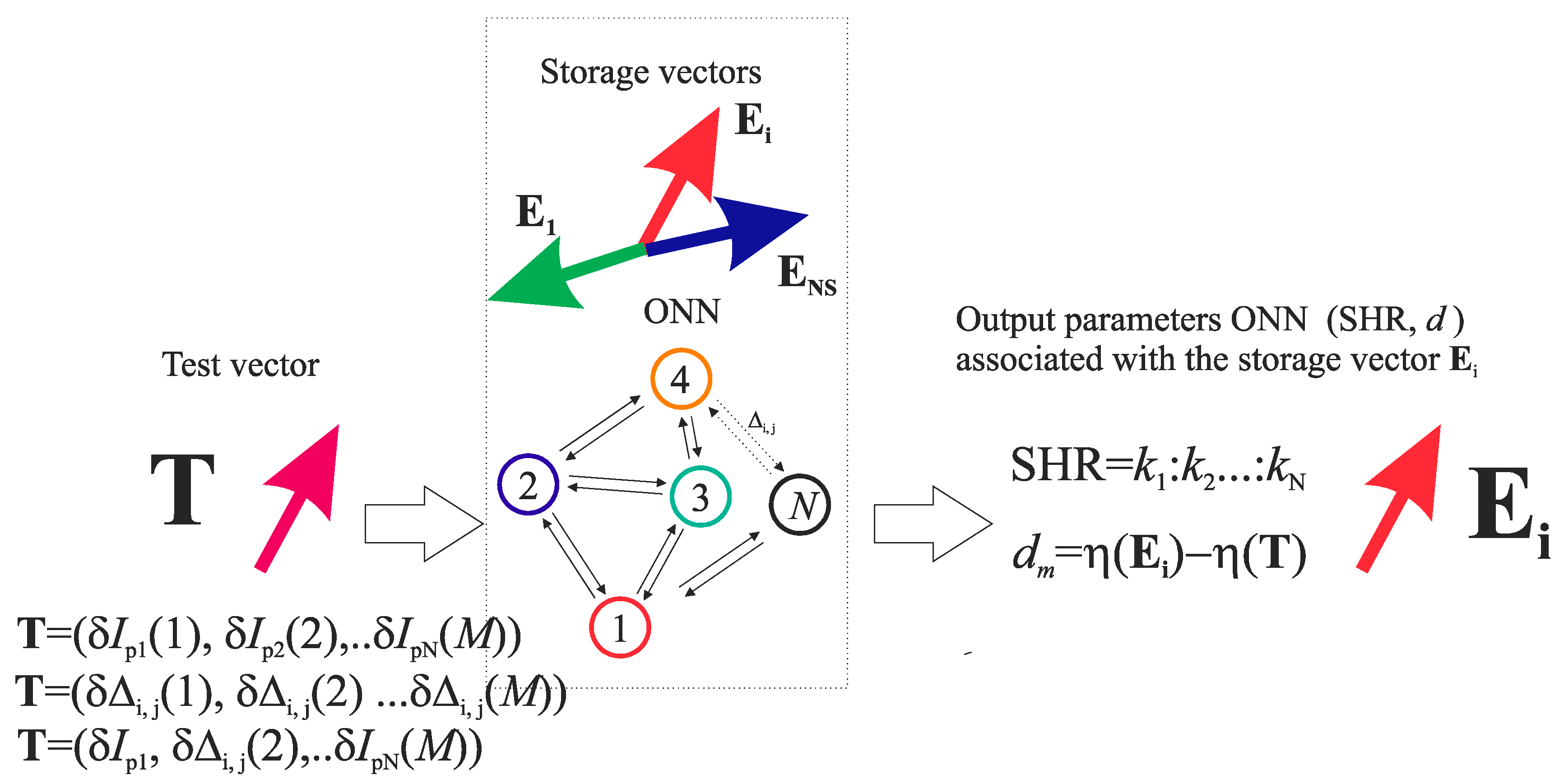
We suggest the following methods of pattern storage and recognition in a neural network, based on the high-order synchronization effect, and its general scheme is given in Figure 4.
2.1.1. Vector Storage and ONN Training
The general algorithm for vector storage and ONN training includes the following steps:
- For storage, arbitrary vectors E1, E2, …, Ei, ..., ENs should be specified. If necessary, control parameters should be transformed into the corresponding coordinate system (for example, a color one, see Figure 3b,c). In general, vectors have dimensionality M and appear as a set of a network parameters that affects the system SHR. For example, they can be either currents, as shown in Figure 3 E = (δIp1(1), δIp2(2), …, δIpN(M)), or they can be coupling strengths between some definite oscillators E = (δΔi,j(1), δΔi,j(2), …, δΔi,j(M)), or mixed parameters E = (δIp1(1), δΔi,j(2), …, δΔi,j(M)) (see Figure 4).
- Then, the network should be trained by the adjustment of the ONN parameters that are not used for the vectors’ determination (coupling strengths, currents of other oscillators in the network, noise level, and synchronization effectiveness threshold ηth). The adjustment is performed until the synchronization areas coincide with the vectors’ ends at the point of maximum value of synchronization effectiveness η (similar network training was used in the work [15]). The adjustment can be performed in two steps.
- First, by using random search until the vectors enter the synchronization area.
- Then, one of gradient methods [29] may be applied to search the maximum η. As a result, each stored vector corresponds to its unique value of SHR and maximum of η(E).
- If the training does not provide a positive result, one more oscillator should be included into the system and coupled with all oscillators already present, thus increasing the number of varied parameters and the number of possible synchronous states Ns. Then, the training should be repeated (see step 2).
2.1.2. Vectors Recognition
The algorithm of test vector T recognition includes the following steps:
- Set the test vector T to the system input through applying shifts to the control parameters (see Figure 4). The vector’s coordinates may be either shifts of currents, or coupling strengths or their combination, as it has been indicated above.
- If one of the conditions is met (T ≈ E1 or T ≈ E2 or … or T ≈ ENS), i.e., coordinates values of T are equal to one of the stored patterns, a transition to the synchronous state will occur and, actually, the act of the corresponding pattern recognition will take place. Which patterns have been exactly recognized can be determined by the value of SHR. The existence of the synchronization areas ensures the vector recognition even at its coordinates’ insignificant displacement from the stored pattern.
- The degree of match dm between the objects may be such magnitude as the difference between the synchronization effectiveness of the stored and the test vectors dm = η(E) − η(T). If the magnitude of η(E) is not known, then to compare the degree of match, the formula dm = 100% − η(T) can be used. The less dm is, the closer vector T is to vector E.
This method is a more complicated version of the method described in [22], where the analogy to the frequency-shift keying method of coding is used and, instead of setting the vector through frequencies E = (δω1, δω2, …, δωN), in our method, the vector is set through the control parameters E1 = (δIp1, δIp2, …, δIpN), that has the same meaning. The principle difference is that here, a high-order synchronization effect is used, thus allowing storage of a multitude of patterns in the ONN.
Besides, as described in the results section, it is more practical to use vector dimensions E’ = (δI1, δI2, …, δIN−1) with one less than the number of oscillators (N − 1).
2.2. Model Object
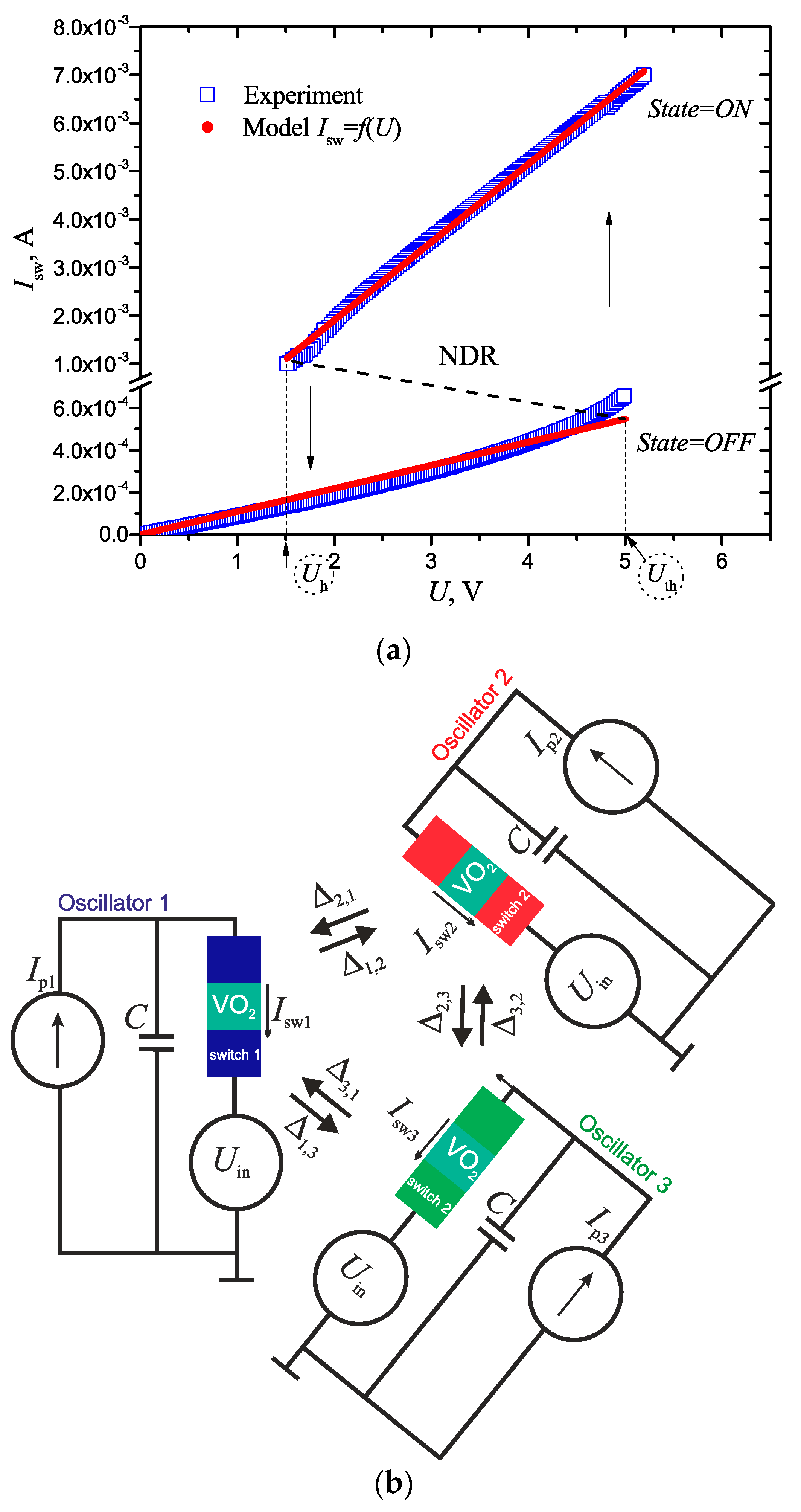
As a model object, we have chosen a neural network composed of three thermally coupled VO2-oscillators, where each oscillator has the scheme of a relaxation oscillator. Our choice is conditioned by the fact that we have done some research in thermal coupling [17,30] and its modeling, however, the coupling may be an electric one (capacitive or resistive [7]). It is known that an electric switching effect is observed in VO2 film-based structures, that is conditioned by a phase metal–insulator transition (MIT) at the moment when the temperature reaches Tt ~ 340 K, because of Joule heating by the passing current Isw [16]. This gives high-impedance (OFF) and low-impedance (ON) branches on I–V characteristics with threshold voltages (OFF→ON) Uth ~ 5 V and holding voltages (ON→OFF) Uh ~ 1.5 V (see Figure 5a). Both branches of I–V characteristics are reasonably well approximated by fsw curve, consisting of two linearized regions with dynamic resistance Roff ~ 9.1 kΩ and Ron ~ 615 Ω:
where Ubv ~0.82 V is bias voltage of a low-impedance region, and State is a switch state.
One of three topologies presented in Figure 1 may be realized, depending on coupling strength magnitudes Δ. At non-zero Δ ≠ 0, the topology is “all-to-all” (Figure 1c); at Δ2,3 = Δ3,2 = 0, the topology is “star” (Figure 1b); and at Δ2,3 = Δ3,2 = Δ1,3 = Δ3,1 = 0, the scheme turns into a two-oscillator one (Figure 1a). The control parameters here are source currents Ip1, Ip2, Ip3, and their variation leads to alteration of the fundamental oscillation frequency F0 of oscillators.
Variations of each oscillator are described by the equation of Kirchhoff’s law:
where Ui(t) is the output voltage taken from the capacitor (C = 100 nF), Isw(i)(t) = fsw(Ui(t) − Uin) is the current passing through a switch, determined by I–V characteristics (1), Ip(i) is the i-th oscillator supply current, respectively, Uin is the amplitude of switch internal noise, and i is the oscillator’s number.
Thermal interaction between the i-th VO2-oscillator and the neighbor ones ((i+)—clockwise and (i−)—counterclockwise of the scheme in Figure 5b) is realized according to the rule
If the states of oscillators State(i+) and State(i−) are on the OFF branch of I–V characteristics, then the threshold voltage of the i-th VO2-oscillator does not change: Uth(i) = Uth. Rule (3) is the same for all oscillators (with regard to cyclic permutation).
Oscillograms of oscillations with ~250,000 points and time interval δt = 10 µs were simulated using Equations (1)–(3). After that, the oscillograms were automatically processed, the synchronization order was determined, and cross-sections of oscillator synchronization areas were built.
The switch parameters did not change in numerical simulation of the results, but current intensities Ip, coupling strength Δ, and noise amplitude Uin varied.
2.3. Method of Calculating a Family of Metrics
To define the synchronization order, we used the family of metrics described above, that consists of two parameters SHR and η.
The problem of finding the high-order synchronization value determined by the ratio of integers SHR = k1:k2:k3:..:kN (see Section 2.1) may be solved in several ways. For example, by direct analysis of all oscillation spectra, or by searching the synchronization order of each pair of oscillators based on the method which we suggested in [17].
It should be noted that, at synchronous state, the frequency sets of fundamental (first) harmonics of oscillators (F10, F20, F30, …, FN0) must be commensurable. This is evident because at the synchronous state, there is a common synchronization frequency Fs, and the equality (Fs = F10·k1 = F20·k2 = … = FN0·kN) is fulfilled. If we divide F10 into all frequencies in the set (F10, F20, F30, …, FN0), then we will get (1, F10/F20, F10/F30, …, F10/FN0) = (1, k2/k1, k3/k1, …, kN/k1), that is, a new set of rational numbers determining pair synchronization of all oscillators in regard to the first oscillator (see [17]).
Thus, the method of specifying all values of k and the synchronization order of the system consisting of N-oscillators comes down to determining the set of pair synchronization fractional values (in regard to the first oscillator) for N-pairs (m1/d1, m2/d2, …, mN−1/dN−1), and to its reduction to a common denominator:
For example, a set of pair synchronization for oscillator pairs (№1–№2) and (№1–№3) in Figure 2 looks like (2/1, 4/3), after reduction to a common denominator (4), we get (2/1, 4/3) → (6/3, 4/3), and SHR = k1:k2:k3 = 3:6:4.
It should also be noted that the algorithm of pair synchronization definition is based on the search of current oscillation peaks, Isw, synchronous in time [17].
The effectiveness of pair synchronization η is determined as the percentage of the durability of all NSHR synchronous periods Ts with the definite SHR, to the whole durability of the processed oscillogram Tall:
If there are several synchronization types with different SHR, then the resulting η is associated with the maximum which, in turn, is compared with the threshold value ηth (in our case 90%). Oscillations are considered synchronized when η exceeds the threshold η ≥ ηth. If the system consists of more than two oscillators, then the total effectiveness η is calculated as the mean value of all oscillator pairs. It should be noted that the proposed methods of SHR and η identification may be used in oscillator systems with noise. It has been noted that the noise increase leads mainly to the decrease of η, while SHR does not normally change.
3. Results
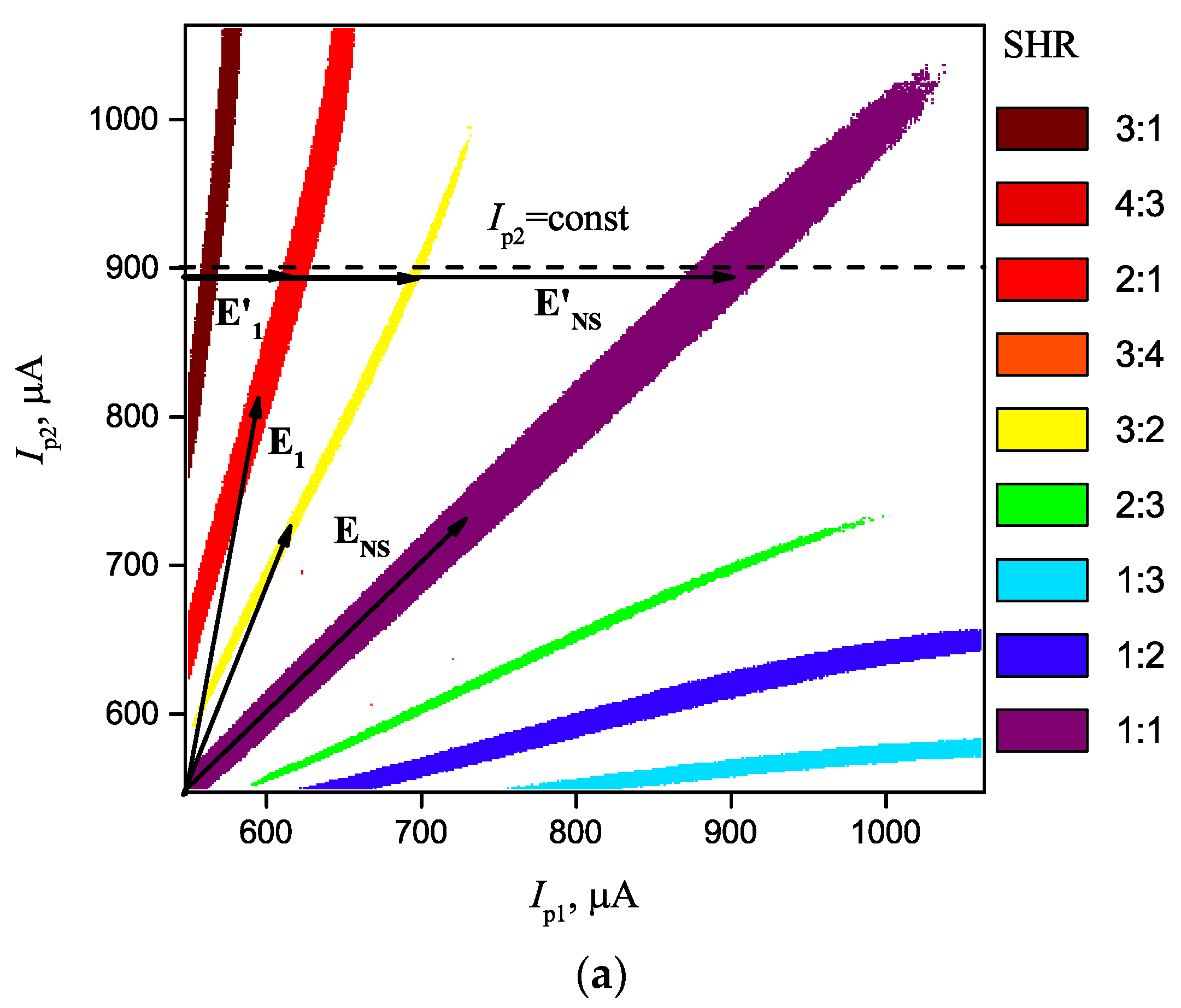
The results of synchronization areas modeling for a two-oscillator scheme (see Figure 1a) are given in Figure 6a. Control parameters are oscillator feed currents Ip1, Ip2, and noise and coupling strength values are Uin = 40 mV and Δ = 0.2 V. It can be seen that there is a whole family of synchronization areas that are called Arnold tongues [23]. The number of possible variants of synchronous states, Ns, in which the system may exist while the control parameters are varied, is Ns = 9. The dimension of the stored vectors in this case is 2, and the coordinates determine current shifts E1 = (δIp1, δIp2), with respect to the origin of coordinates.
The problem here is that the synchronization areas are long-ranged (of Arnold’s tongues shape) therefore, there is a wide range of stored pattern coordinates which bring the system into a certain synchronous state. The solution lies in narrowing the dispersion of stored pattern coordinates by using vectors E’1 = (δI1, δI2, …, δIN−1) of a dimension one less than the number of oscillators (N − 1), in this case, E’1 = (δI1). In practice, this means that we fix the current for one oscillator, and vary the currents for the others (see Figure 6a, dashed line Ip2 = const). Thus, we eliminate the ambiguity of synchronization definition by one of the vector coordinates, and the areas of possible synchronization are narrowed.
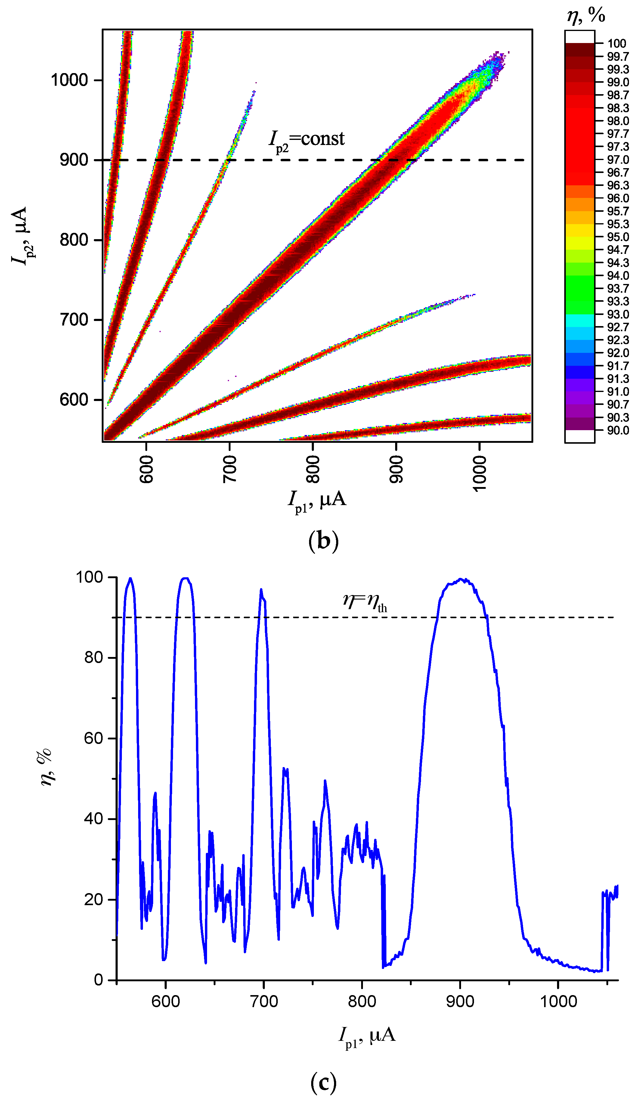
Figure 6b shows the distribution of synchronization effectiveness inside the Arnold’s tongues. It can be seen that η falls down to the edges of synchronization areas, whereas maximum of η has a progressive form in the area of control parameters, and is placed in the line in the center. When a cross-section is made (shown in Figure 6c), we can observe local maximums of η inside the synchronization areas and this is another argument to use the gradient search method in the algorithm of the network training. According to the above proposed method of recognition, the magnitude dm = η(E’) − η(T) may serve as the parameter of the degree of match between the test and stored vectors.
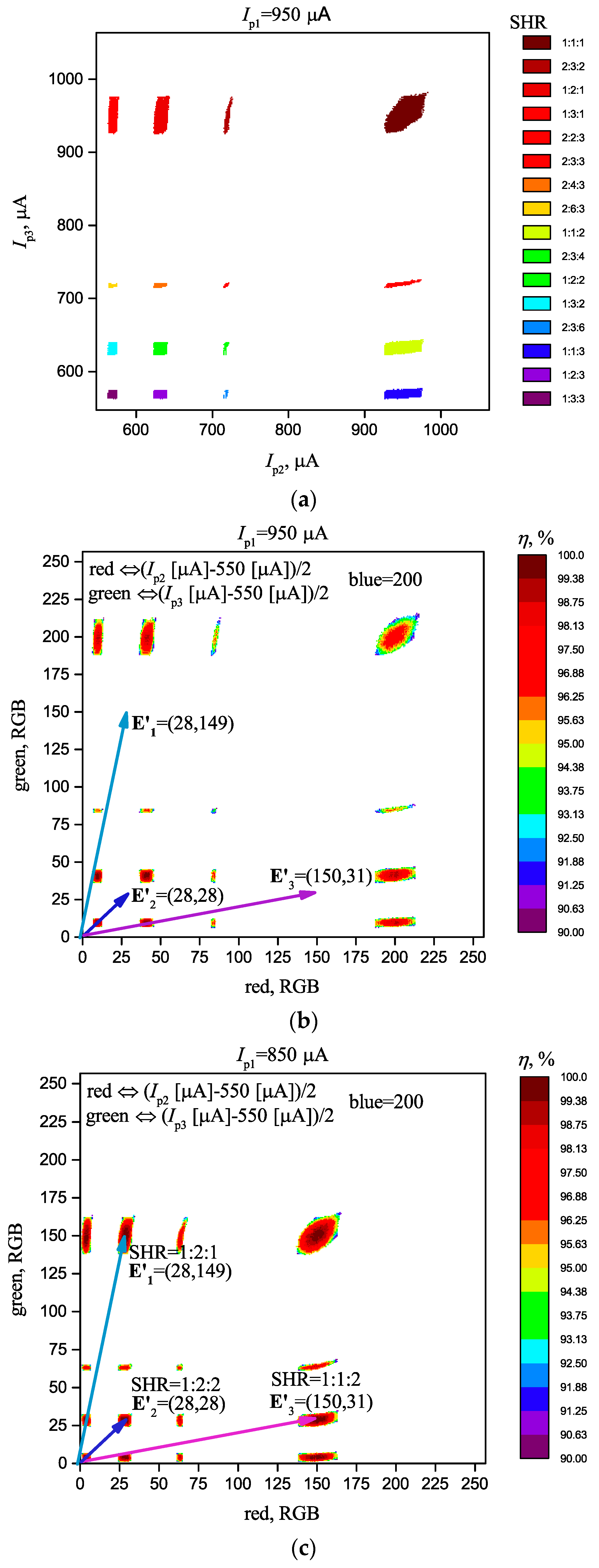
Figure 7 shows cross-sections of synchronization areas for a system consisting of three oscillators (“star”, see Figure 1b) at fixed current on the first oscillator Ip1 = 950 µA, and parameters Uin = 40 mV and Δ = 0.2 V, that are similar to a two-oscillator scheme.
It can be seen that the synchronization areas are separate isolated regions that are suitable for setting vectors E’ of dimension 2. In this case, with all other things being equal, Ns depends on the topology, and is Ns = 16 for a “star” connection and Ns = 14 for an “all-to-all” connection. The area shape also depends on the topology.
When comparing the values for two- and three-oscillator schemes with the same parameters, including the topology, we may propose a general rule stating that with the increase of the number of interacting oscillators, Ns, increases. Yet, this is evident as the number of freedom degree increases at determining the synchronization value SHR = k1:k2:k3:..:kN. Nevertheless, as we show below, at certain parameters, there are some exceptions from the general rule.
Distribution of synchronization effectiveness is shown in Figure 7b. Here, we can see that a local maximum η is present in each area, and it can be used for vector storage and recognition, according to the method described in Section 2.1.
Below, we will give an example of a vector storage and recognition (that determine colors RGB) by using the algorithm described in Section 2.1 for the scheme “star”.
3.1. Vector Storage and ONN Training
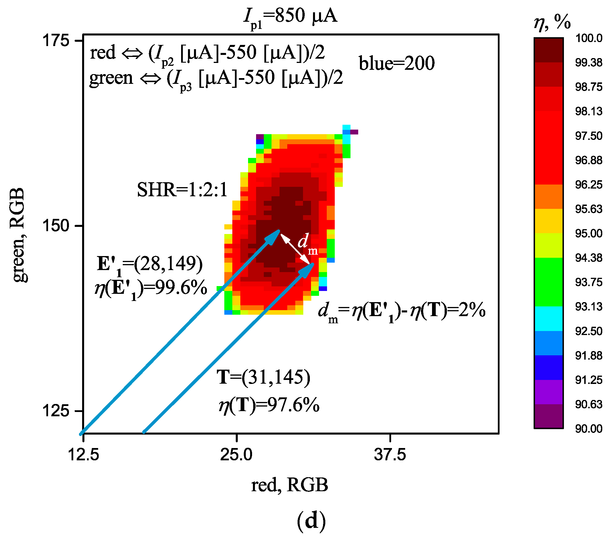
Step 1: Suppose that we have to store three vectors that correspond to three colors RGB at the constant level of the component blue = 200, with coordinates E’1 = (28, 149), E’2 = (28, 28), and E’3 = (150, 31). It should be noted that the number of coordinates in each vector is one unit less than the number of oscillators, and is equal two. As it has been explained above, this is necessary to narrow the area of possible synchronization and to reduce the recognition ambiguity. Liner transformation of coordinates, from the current parameters into color parameters, should be thought over initially. In our case, we used the following formulas: red (Ip2 [µA] − 550 [µA])/2 and green (Ip3 [µA] − 550 [µA])/2. After the working area has been transformed, we set three vectors, as shown in Figure 7b.
Step 2: Then, we start the system training by adjusting parameters of the ONN (Ip1 and coupling strength Δi,j) in such a way that the synchronization areas are obtained on the vectors at the point of maximum η. A fine adjustment for the maximum η can be done by using the gradient search. As a result, we have found that at Δi,j = Δ = 0.2 V, and Ip1 = 850 µA, the system complies with the assigned task.
Step 3: As we have achieved a positive result after the network training, the vector recording may be considered completed at this step.
3.2. Vectors Recognition
When test vector T ≈ E’1 is supplied, the neural network is transformed into a synchronous state with the synchronization order 1:2:1. At T ≈ E’2, we get SHR = 1:2:2. At T ≈ E’3, we get SHR = 1:1:2. In each case, the degree of match dm = η(E’) − η(T) is calculated, that determines the degree of match of vector T with the stored vectors. For example, at T = (31,145), the system transfers to SHR = 1:2:1 and the vector is recognized as the vector E’1 = (28,149), with the degree of match dm = η(E’1) − η(T) = 2% (see Figure 7d).
Step 1: Set the test vector T = (31,145).
Step 2: Determine that the system transfers to SHR = 1:2:1, and the vector is recognized as the vector E’1 = (28,149).
Step 3: Determine the degree of match dm = η(E’1) − η(T) = 2%.
Thus, we have performed storage and recognition of three various patterns with RGB color, although the capacity of this system is considerably higher and enables storing up to 16 patterns simultaneously.
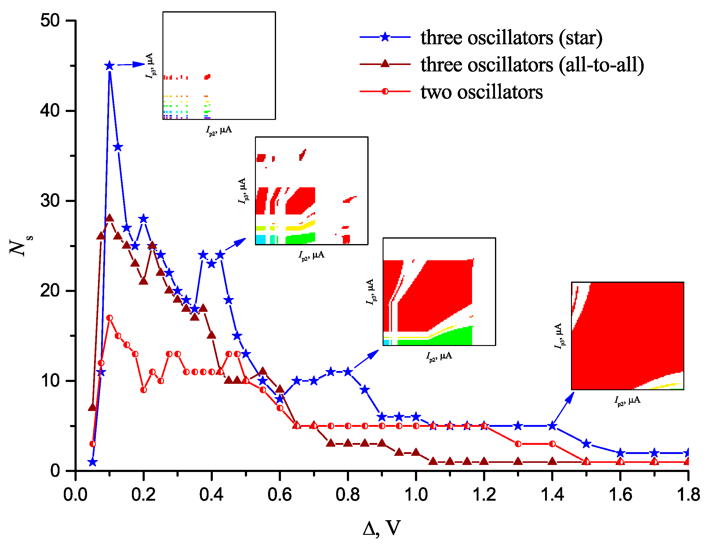
Figure 8 shows the dependence of the number of synchronous states Ns on Δ at three different configurations of a neural network at the constant noise level Uin = 20 mV. The existence of the main maximum Ns is evident at some optimal value Δopt, in this case, this value is roughly the same as Δopt ~0.1 V for all configurations, and does not depend on the oscillator number. The existence of the curve maximum Ns(Δ) reduplicates our results obtained in [28] for a two-oscillator scheme. Inalterability of Δopt for a different number of oscillators N, with all other parameters being equal, might be explained by the fact that, with the increase of the number of freedom degrees for synchronization order, SHR = k1:k2:k3:..:kN, the value of Ns has the tendency to grow.
We should also note the general tendency for Ns to decrease when the coupling strength Δ grows above Δopt and, at its large values, the system tends to the lowest possible Ns = 1 with synchronization value 1:1:1. This is related to the fact that, with the increase of Δ, the surface of certain synchronization areas increase. Neighboring areas merge; in this case, the synchronization order of the resulting area predominantly consists of lower harmonic numbers. As the dimension of the control parameters is limited, such growth of synchronization area surfaces irrevocably results in a decrease of their number and value of Ns. The insertions in Figure 8 show the evolution of synchronization areas and demonstrate the effect of their merging with Δ growth.
Besides, we should note the existence of local maximums at Δ > Δopt. In turn, this is related to the fact that, in the presence of noise in the neural network, the increase of Δ may result in the development of new synchronization areas at the control parameters values that previously corresponded to the non-synchronous state of the system. Therefore, in a general case, the curve Ns(Δ) may have a complicated shape with several maximums, as we can see in Figure 8.
In addition, the initial sharp growth of all three curves at the plot should be noted when Δ increases from 0 to Δopt. The latter is due to synchronization effect degradation at Δ→0.
When comparing the curves, it may be noted that the increase of the oscillator number in the network leads to the increase of the maximum value of Ns in the system; this does not contradict the rule suggested above. For example, Ns_max = 17 is for two oscillators, for three-oscillator schemes, and Ns_max = 28 and Ns_max = 45 are for the “all-to-all” and “star” schemes, respectively. At the same time, at certain values of coupling strength (for example, at Δ = 1.1 V), the value of Ns for a two-oscillator scheme may be even higher. Also, the regularity that the “star” topology has higher Ns than the topology of “all-to-all” is observed. All of these things mean that the increase of the coupling number may contribute to the effect of system desynchronization and decrease of Ns, as it seems that oscillators prevent each other from synchronization.
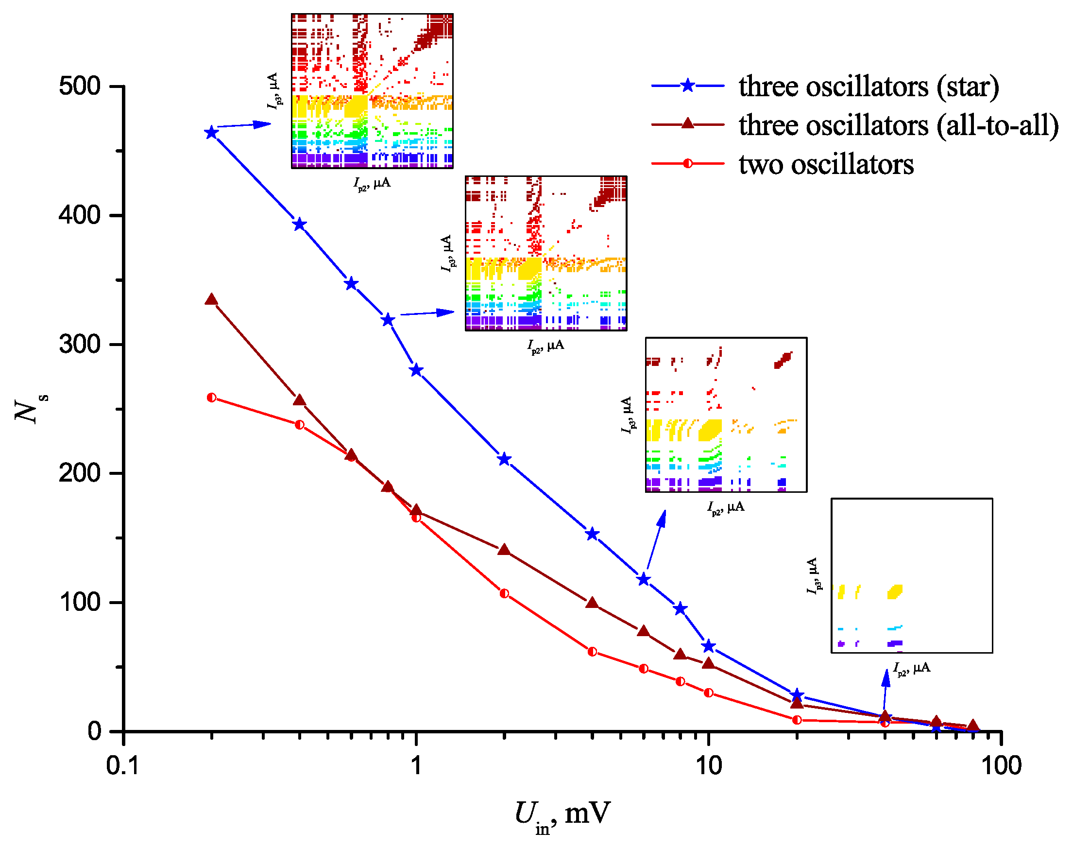
Figure 9 shows the curve of Ns vs noise level in the system Uin at the same coupling strength Δ = 0.2 V, for three configurations of an oscillator neural network. The general trend for the decrease of Ns at the noise amplitude increase is due to the decrease of the surface of synchronous areas which eventually disappear (see the insertions in Figure 9).
It should also be noted that the general rule is observed: stating that the value of Ns for a three-oscillator configuration “star” is higher than that for a two-oscillator one. The shapes of curves Ns(Uin) are similar, which indicated that the physics of noise effect on the network is similar, and does not depend on the number of oscillators.
Comparing the above curves Ns(Δ) and Ns(Uin), it may be seen that the number of synchronization areas Ns_max in our models may reach Ns_max ~450, at an optimal coupling strength value Δ = Δopt, and at lowered noise Uin = 10 μV, it increases to Ns_max ~650.
4. Conclusions
A new method of pattern storage and recognition in an impulse oscillator neural network based on resistive switches and the high-order synchronization effect is presented, using computational modeling of two- and three-oscillator schemes with thermally coupled VO2-switches.
Our method allows storage of a multitude of patterns Ns, where each state of the system is characterized by synchronization order SHR = k1:k2:k3:..:kN.
A general rule is suggested, stating that Ns increases with the increase of the number of interacting oscillators. The modeling demonstrates achievement of Ns of several orders: Ns ~650 for a three-oscillator scheme and Ns ~260 for a two-oscillator scheme.
Several regularities of functional characteristics of such ONNs have been obtained; in particular, the existence of an optimal coupling strength between oscillators has been revealed, when the number of synchronous states is maximal. A general tendency for Ns decrease with the increase of coupling strength and switches’ inner noise amplitude, is also shown.
The algorithm of vector storage, network training, and test vector recognition has been proposed, where the parameter of synchronization effectiveness is used as the degree of match. It has been shown that it is more expedient to use the number of coordinates in each vector at least one unit less than the number of oscillators (N − 1), because it is necessary to narrow the area of possible synchronization and to lower the recognition ambiguity.
By contrast, for example, to the FSK method [22], such an approach to the problem of pattern storage and recognition allows one to significantly increase the information capacity, Ns, of a neural network using the minimum number of neural oscillators. In addition, the proposed concept of pulse synchronization definition, through calculation of a family of metrics, opens a natural way for gradient method application to an oscillator network training (optimization).
Although the research has been performed on a certain model object (VO2 thermally coupled relaxation oscillators), the demonstrated method of pattern storage and recognition is sufficiently general, and the fundamental character of the obtained regularities may be the subject of further research of ONNs, of various mechanisms and oscillator-coupling topology.
Author Contributions
Conceptualization, A.V. and M.B.; methodology, V.P. and P.B.; software, A.V.; validation, P.B.; writing—original draft preparation, A.V., M.B. and V.P.; project administration, A.V.
Funding
This research was supported by Russian Science Foundation (grant no. 16-19-00135).
Acknowledgments
The authors express their gratitude to O. Dobrynina for some valuable comments in the course of the article translation.
Conflicts of Interest
The authors declare no conflict of interest.
References
- Heaton, J. Artificial Intelligence for Humans; Createspace Independent Publishing: Scotts Valley, CA, USA, 2015; ISBN 9781505714340. [Google Scholar]
- Bishop, C.M. Neural Networks for Pattern Recognition; Clarendon Press: New York, NY, USA, 1995; ISBN 0198538642. [Google Scholar]
- Hopfield, J.J.; Tank, D.W. Computing with neural circuits: A model. Science 1986, 233, 625–633. [Google Scholar] [CrossRef] [PubMed]
- Strogatz, S.H. From Kuramoto to Crawford: Exploring the onset of synchronization in populations of coupled oscillators. Phys. D Nonlinear Phenom. 2000, 143, 1–20. [Google Scholar] [CrossRef]
- Vodenicarevic, D.; Locatelli, N.; Abreu Araujo, F.; Grollier, J.; Querlioz, D. A Nanotechnology-Ready Computing Scheme based on a Weakly Coupled Oscillator Network. Sci. Rep. 2017, 7, 44772. [Google Scholar] [CrossRef] [PubMed] [Green Version]
- Nakano, H.; Saito, T. Grouping Synchronization in a Pulse-Coupled Network of Chaotic Spiking Oscillators. IEEE Trans. Neural Netw. 2004, 15, 1018–1026. [Google Scholar] [CrossRef] [PubMed]
- Velichko, A.; Belyaev, M.; Putrolaynen, V.; Pergament, A.; Perminov, V. Switching dynamics of single and coupled VO2-based oscillators as elements of neural networks. Int. J. Mod. Phys. B 2017, 31, 1650261. [Google Scholar] [CrossRef]
- Shukla, N.; Parihar, A.; Cotter, M.; Barth, M.; Li, X.; Chandramoorthy, N.; Paik, H.; Schlom, D.G.; Narayanan, V.; Raychowdhury, A.; Datta, S. Pairwise coupled hybrid vanadium dioxide-MOSFET (HVFET) oscillators for non-boolean associative computing. In Proceedings of the 2014 IEEE International Electron Devices Meeting, San Francisco, CA, USA, 15–17 December 2014; pp. 28.7.1–28.7.4. [Google Scholar]
- Khitun, A.G.; Geremew, A.K.; Balandin, A.A. Transistor-Less Logic Circuits Implemented With 2-D Charge Density Wave Devices. IEEE Electron. Device Lett. 2018, 39, 1449–1452. [Google Scholar] [CrossRef]
- Khitun, A.; Liu, G.; Balandin, A.A. Two-dimensional oscillatory neural network based on room-temperature charge-density-wave devices. IEEE Trans. Nanotechnol. 2017, 16, 860–867. [Google Scholar] [CrossRef]
- Liu, G.; Debnath, B.; Pope, T.R.; Salguero, T.T.; Lake, R.K.; Balandin, A.A. A charge-density-wave oscillator based on an integrated tantalum disulfide-boron nitride-graphene device operating at room temperature. Nat. Nanotechnol. 2016, 11, 845–850. [Google Scholar] [CrossRef] [PubMed]
- Ghosh, S. Generation of high-frequency power oscillation by astable mode arcing with SCR switched inductor. IEEE J. Solid-State Circuits 1984, 19, 269–271. [Google Scholar] [CrossRef]
- Chen, C.; Mathews, R.; Mahoney, L.; Calawa, S.; Sage, J.; Molvar, K.; Parker, C.; Maki, P.; Sollner, T.C.L. Resonant-tunneling-diode relaxation oscillator. Solid. State. Electron. 2000, 44, 1853–1856. [Google Scholar] [CrossRef]
- Sharma, A.A.; Bain, J.A.; Weldon, J.A. Phase Coupling and Control of Oxide-Based Oscillators for Neuromorphic Computing. IEEE J. Explor. Solid-State Comput. Devices Circuits 2015, 1, 58–66. [Google Scholar] [CrossRef]
- Romera, M.; Talatchian, P.; Tsunegi, S.; Araujo, F.A.; Cros, V.; Bortolotti, P.; Yakushiji, K.; Fukushima, A.; Kubota, H.; Yuasa, S.; et al. Vowel recognition with four coupled spin-torque nano-oscillators. arXiv, 2018; arXiv:1711.02704. [Google Scholar]
- Belyaev, M.A.; Boriskov, P.P.; Velichko, A.A.; Pergament, A.L.; Putrolainen, V.V.; Ryabokon’, D.V.; Stefanovich, G.B.; Sysun, V.I.; Khanin, S.D. Switching Channel Development Dynamics in Planar Structures on the Basis of Vanadium Dioxide. Phys. Solid State 2018, 60, 447–456. [Google Scholar] [CrossRef]
- Velichko, A.; Belyaev, M.; Putrolaynen, V.; Perminov, V.; Pergament, A. Thermal coupling and effect of subharmonic synchronization in a system of two VO2 based oscillators. Solid State Electron. 2018, 141, 40–49. [Google Scholar] [CrossRef]
- Sakai, J. High-efficiency voltage oscillation in VO2 planer-type junctions with infinite negative differential resistance. J. Appl. Phys. 2008, 103, 103708. [Google Scholar] [CrossRef]
- Hoppensteadt, F.C.; Izhikevich, E.M. Oscillatory Neurocomputers with Dynamic Connectivity. Phys. Rev. Lett. 1999, 82, 2983–2986. [Google Scholar] [CrossRef]
- Hoppensteadt, F.C.; Izhikevich, E.M. Pattern recognition via synchronization in phase-locked loop neural networks. IEEE Trans. Neural Netw. 2000, 11, 734–738. [Google Scholar] [CrossRef] [PubMed] [Green Version]
- Izhikevich, E.M. Weakly pulse-coupled oscillators, FM interactions, synchronization, and oscillatory associative memory. IEEE Trans. Neural Netw. 1999, 10, 508–526. [Google Scholar] [CrossRef] [PubMed] [Green Version]
- Nikonov, D.E.; Csaba, G.; Porod, W.; Shibata, T.; Voils, D.; Hammerstrom, D.; Young, I.A.; Bourianoff, G.I. Coupled-Oscillator Associative Memory Array Operation for Pattern Recognition. IEEE J. Explor. Solid-State Comput. Devices Circuits 2015, 1, 85–93. [Google Scholar] [CrossRef]
- Pikovsky, A.; Rosenblum, M.; Kurths, J. (Jürgen) Synchronization: A Universal Concept in Nonlinear Sciences; Cambridge University Press: Cambridge, UK, 2003; ISBN 9780521533522. [Google Scholar]
- Theodoridis, S.; Koutroumbas, K. Pattern Recognition; Academic Press: Cambridge, MA, USA, 2009; ISBN 9781597492720. [Google Scholar]
- Kumar, A.; Mohanty, P. Autoassociative Memory and Pattern Recognition in Micromechanical Oscillator Network. Sci. Rep. 2017, 7, 411. [Google Scholar] [CrossRef] [PubMed]
- Shukla, N.; Parihar, A.; Freeman, E.; Paik, H.; Stone, G.; Narayanan, V.; Wen, H.; Cai, Z.; Gopalan, V.; Engel-Herbert, R.; et al. Synchronized charge oscillations in correlated electron systems. Sci. Rep. 2014, 4, 4964. [Google Scholar] [CrossRef]
- Hoppensteadt, F.C.; Izhikevich, E.M. Synchronization of laser oscillators, associative memory, and optical neurocomputing. Phys. Rev. E 2000, 62, 4010–4013. [Google Scholar] [CrossRef]
- Velichko, A.; Putrolaynen, V.; Belyaev, M. Effects of Higher Order and Long-Range Synchronizations for Classification and Computing in Oscillator-Based Spiking Neural Networks. arXiv, 2018; arXiv:1804.03395. [Google Scholar]
- Gill, P.E.; Murray, W.; Wright, M.H. Practical Optimization; Emerald Group Publishing: Bingley, UK, 1982; ISBN 0122839528. [Google Scholar]
- Velichko, A.; Belyaev, M.; Putrolaynen, V.; Perminov, V.; Pergament, A. Modeling of thermal coupling in VO2-based oscillatory neural networks. Solid State Electron. 2018, 139, 8–14. [Google Scholar] [CrossRef]
Figure 1.
Examples of two (a) and three (b) oscillators connection into a neural network using topologies “star” (b), “all-to-all” (c), and N-oscillators using mixed topology (d), where Δi,j indicates the value of the i-th oscillator effect on the j-th one.
Figure 1.
Examples of two (a) and three (b) oscillators connection into a neural network using topologies “star” (b), “all-to-all” (c), and N-oscillators using mixed topology (d), where Δi,j indicates the value of the i-th oscillator effect on the j-th one.

Figure 2.
Example of oscillation spectra of three electric oscillators at synchronization order subharmonic ratio (SHR) = k1:k2:k3 = 3:6:4, where ISW is the current amplitude of a signal in an oscillator, F0 is first harmonic, k is the harmonic number at the synchronization frequency Fs.
Figure 2.
Example of oscillation spectra of three electric oscillators at synchronization order subharmonic ratio (SHR) = k1:k2:k3 = 3:6:4, where ISW is the current amplitude of a signal in an oscillator, F0 is first harmonic, k is the harmonic number at the synchronization frequency Fs.

Figure 3.
(a) Schematic representation of the synchronization areas for a three-oscillator scheme; (b) Examples of the vector and object’s RGB color association, that illustrate the algorithm of the network training and recognition (c).
Figure 3.
(a) Schematic representation of the synchronization areas for a three-oscillator scheme; (b) Examples of the vector and object’s RGB color association, that illustrate the algorithm of the network training and recognition (c).


Figure 4.
Schematic representation of pattern recognition principle by using oscillator neural network (ONN), where M is the dimensionality of the test vector T, N is the number of oscillators, Ns is the maximal number of the stored vectors E.
Figure 4.
Schematic representation of pattern recognition principle by using oscillator neural network (ONN), where M is the dimensionality of the test vector T, N is the number of oscillators, Ns is the maximal number of the stored vectors E.

Figure 5.
Experimental and model I–V characteristics of VO2-switch (a); a model scheme of a neural network based on three oscillators circuits with VO2-switches interacting via thermal coupling (b).
Figure 5.
Experimental and model I–V characteristics of VO2-switch (a); a model scheme of a neural network based on three oscillators circuits with VO2-switches interacting via thermal coupling (b).

Figure 6.
Example of synchronization areas for a two-oscillator scheme (a). The arrows show sampled vectors E and E’, in regard to the origin of coordinates. Distribution of η for a two-oscillator scheme (b). Cross-section η at I2 = 900 µA (c).
Figure 6.
Example of synchronization areas for a two-oscillator scheme (a). The arrows show sampled vectors E and E’, in regard to the origin of coordinates. Distribution of η for a two-oscillator scheme (b). Cross-section η at I2 = 900 µA (c).


Figure 7.
(a) Synchronization areas with SHR for a three-oscillator scheme “star” at Ip1 = 950 µA; (b) Distribution of synchronization effectiveness η with the set vectors E’ at Ip1 = 950 µA; (c) Distribution of synchronization effectiveness η with the set vectors E’ at Ip1 = 850 µA, on an enlarged scale with vector T (d); Levels of coupling Δ = 0.2 V and noise Uin = 40 mV.


Figure 8.
Dependence Ns on coupling strength value between oscillators Δ at various configurations of oscillator neural network and constant noise level Uin = 20 mV. The insertions show the evolution of synchronization areas and demonstrate the effect of their merging with Δ growth.
Figure 8.
Dependence Ns on coupling strength value between oscillators Δ at various configurations of oscillator neural network and constant noise level Uin = 20 mV. The insertions show the evolution of synchronization areas and demonstrate the effect of their merging with Δ growth.

Figure 9.
Dependence Ns on noise level Uin at various configurations of an oscillator neural network at the same coupling strength Δ = 0.2 V.
Figure 9.
Dependence Ns on noise level Uin at various configurations of an oscillator neural network at the same coupling strength Δ = 0.2 V.

© 2018 by the authors. Licensee MDPI, Basel, Switzerland. This article is an open access article distributed under the terms and conditions of the Creative Commons Attribution (CC BY) license (http://creativecommons.org/licenses/by/4.0/).
Share and Cite
MDPI and ACS Style
Velichko, A.; Belyaev, M.; Putrolaynen, V.; Boriskov, P. A New Method of the Pattern Storage and Recognition in Oscillatory Neural Networks Based on Resistive Switches. Electronics 2018, 7, 266. https://doi.org/10.3390/electronics7100266
AMA Style
Velichko A, Belyaev M, Putrolaynen V, Boriskov P. A New Method of the Pattern Storage and Recognition in Oscillatory Neural Networks Based on Resistive Switches. Electronics. 2018; 7(10):266. https://doi.org/10.3390/electronics7100266
Chicago/Turabian StyleVelichko, Andrei, Maksim Belyaev, Vadim Putrolaynen, and Petr Boriskov. 2018. "A New Method of the Pattern Storage and Recognition in Oscillatory Neural Networks Based on Resistive Switches" Electronics 7, no. 10: 266. https://doi.org/10.3390/electronics7100266
Note that from the first issue of 2016, this journal uses article numbers instead of page numbers. See further details here.