New Nonlinear Second-Order Phase-Locked Loop with Adaptive Bandwidth Regulation


1
School of Information, Xi’an University of Finance and Economics, Xi’an 710100, China
2
School of Aerospace Science and Technology, Xidian University, Xi’an 710126, China
*
Author to whom correspondence should be addressed.
Electronics 2018, 7(12), 346; https://doi.org/10.3390/electronics7120346
Submission received: 7 September 2018
/
Revised: 12 November 2018
/
Accepted: 20 November 2018
/
Published: 23 November 2018
(This article belongs to the Section Microwave and Wireless Communications)
Abstract
:Synchronization of large acquisition bandwidth brings great challenges to the traditional second-order phase-locked loop (PLL). To address the contradiction between acquisition bandwidth and noise suppression capability of the traditional PLL, a new second-order PLL coupled with a nonlinear element is proposed. The proposed nonlinear second-order PLL regulates the loop noise bandwidth adaptively by the nonlinear module. When a large input–output phase error occurs, this PLL reduces the frequency offset quickly by taking advantage of the large bandwidth. When the phase error is reduced by the loop control, the proposed PLL suppresses noises by using the small bandwidth to increase the tracking accuracy. Simulation results demonstrate that the tracking speed of the proposed PLL is increased considerably, and its acquisition bandwidth is increased to 18.8 kHz compared with that of the traditional second-order PLL (4 kHz).
1. Introduction
Phase-locked loop (PLL) is widely applied in synchronization of communication systems as a phase follow-up system [1,2,3]. Phase-locked loop is also extensively used in distribution grids and high-voltage DC transmission systems [4,5,6]. Compared with other orders of PLL, the second-order PLL is more preferred in actual engineering due to its absolute stability and easy implementation [7,8].
Although the large loop bandwidth can lock the loop quickly, the loop noise suppression capability declines. The loop is generally designed with a small bandwidth to realize normal operation of the PLL under low signal-to-noise ratio, but this loop has poor dynamic adaptability [9,10,11]. In this study, both noise rejection and fast locking performance are required aspects for the PLL with regard to the area of synchronous receiving highly dynamic telemetry or GPS signals. Additionally, PLL has wide applications in cellular networks for carrier synchronization, especially the D2D communications which support the cellular networks [12,13]. In addition, the phase-locked loop is extensively applicable in image/video and signal processing fields for accurate signal synchronization [14]. Furthermore, the PLL also has a find application in real-time motion detection for automated video surveillance systems [15]. The applicability of the phase-locked loop in real applications is very extensive, especially in communication networks. However, an irreconcilable contradiction exists between the tracking speed and accuracy of the traditional second-order PLL, and this contradiction is an important consideration in engineering applications [6,16]. Humphreys [17] analyzed the performance of PLL based on the Kalman filter in GPS under the influence of ionospheric scintillation. The PLL based on the Kalman filter can still maintain the locking state under serious scintillation (Scintillation index > 0.9) when the carrier-to-noise ratio decreases from 42 dB–Hz to 9 dB–Hz. The serious impacts of integral time on PLL based on the Kalman filter demand accurate processing and noise models. Nevertheless, these models are difficult to be acquired in special application environment and consume long tracking time. Ganguly [18] estimated the carrier phase by frequency-locked loop (FLL)-assisted PLL. Given the large acquisition range of FLL, this method can switch over three states depending on the quality of received signals. Specifically, this FLL tracks the object by using the pure PLL at slow changes in carrier frequency and by using the FLL-assisted PLL at the rapid changes in carrier frequency and phases. The loop is unlocked at the PLL tracking. The FLL-assisted PLL increases the acquisition and tracking speeds but still fails to reconcile the contradiction between the tracking speed and accuracy based on the traditional PLL. Chiou [19] proposed the vector tracking loop in 2008 and estimated carrier phase and Doppler frequency in an independent channel by using all available channels. On the one hand, bad channels can use other good channels for resistance. On the other hand, bad channels can contaminate healthy channels. Francesco Cupertino [20] suggested using the PLL algorithm based on Discrete Fourier Transform (DFT) to compromise the contradiction between large acquisition bandwidth and tracking accuracy. The phase discriminator was utilized to realize the DFT algorithm. Simulation results demonstrated that the PLL based on DFT increases the acquisition speed and protects the noise robustness. However, the phase discriminator in the algorithm is achieved by DFT and increases the complexity of engineering projects.
Considering the PLL with adaptive bandwidth, a set of new algorithms are proposed [21,22,23]. Through estimating the error signal of the discriminator, the algorithm proposed in Reference [22] adaptively adjusts the parameters of the loop filter to optimize the measurement accuracy of the carrier phase. Nevertheless, the parameters of the loop filter cannot be optimized rapidly because of the implementation complexity of the algorithm. Similarly, the method presented in Reference [21] is based on real-time estimations of the dynamics and signal-to-noise ratio of the incoming signals, which are used to compute the better compromise between the equivalent noise bandwidth and the steady state error factor of the loops. The performance depends on an appropriate selection of tracking loop parameters and the characteristics of the PLL itself does not change. Without the necessity of switching circuit elements in the loop filter, Cicero S. [23] proposed an adaptive PLL tuning system architecture. However, a high Signal-to-Noise Ratio (SNR) is always demanded. Those algorithms can improve the robustness of the PLL. Their performances depend on an appropriate selection of tracking loop parameters. On the other hand, they could be external auxiliary factors that will increase the complexity of implementation. All existing tracking algorithms do not change the characteristics of the traditional PLL itself to balance the contradiction between low noise and fast locking performance.
In this study, a nonlinear element is coupled into the traditional second-order PLL based on the working principle of traditional PLL and the nonlinear control idea. The new nonlinear second-order PLL can conduct adaptive regulation over loop noise bandwidth by the control effect of the nonlinear element. When a large input–output phase error occurs, the proposed PLL decreases the phase error quickly by taking advantage of the loop bandwidth. When the phase error decreases gradually due to the control effect of the loop, the method suppresses noises by using the small bandwidth and finally the loop locks accurately. Such new PLL breaks restrictions, updates performance, and balances the tracking speed and accuracy of the traditional PLL.
2. Materials and Methods
2.1. Mathematical Model of the Traditional Second-Order PLL
Phase-locked loop is a closed feedback system used to synchronize the frequency and phase of the output signal into the input signal. Figure 1a illustrates the structure of the traditional second-order PLL. It is mainly composed of three parts [24]: (1) phase discriminator (PD), (2) loop filter (LP), and (3) voltage-controlled oscillator (VCO) (Figure 1a). The three components are connected in a series. In addition, the output of the VCO is feedback connected to the other input port of the phase discriminator. Figure 1b presents the corresponding model of the second-order PLL. The phase discriminator is modeled as a multiplier. The loop filter is modeled as the corresponding transfer function, which is an ideal integrator. And, the voltage-controlled oscillator is modeled as an integrator. The oscillating frequency of the VCO is controlled by the output, namely the control voltage, of the loop filter.
Supposing the input signal of the PLL is
where Ai is the amplitude of input signal, ωi is the angular frequency of input signal, Φi is the initial phase of input signal, and ni(t) is the sinusoidal input noise, i.e., tone interference, the amplitude of output signal of the PLL is
where Ao is the amplitude of input signal, ωo is the angular frequency of output signal, Φo is the phase of output signal, and Φn is the phase noise of the output signal.
The state equations of traditional second-order PLL are constructed in accordance with Figure 1. They are expressed as
In the state Equation (3), the PD in the PLL is modeled into a multiplying unit, and its gain is Kd. Sensitivity of the VCO is Ko. The amplitudes of the input and output signals are normalized into 1. K is the loop gain, and K = 1/2 × Kd × Ko. τ1 and τ2 are time constants of the ideal integral filter. Uc(t) is the control voltage of VCO.
In the state equations, the output signal phase of the traditional second-order PLL is completely determined by the output signal of the LP. Therefore, LP design is the key in the design of traditional PLL. After the LP design is completed, the bandwidth of traditional PLL is fixed. Given the large frequency offset of input and output signals and even dynamic frequency changes in the input signal (i.e., synchronous receiving highly dynamic GPS signals), the large loop bandwidth is required to increase the acquisition bandwidth to guarantee a satisfactory tracking speed. However, large loop bandwidth weakens noise suppression ability and reduces tracking accuracy, thereby influencing receiving and demodulation of GPS signals. However, if small loop bandwidth is used to suppress noises, then the requirements on tracking speed of large bandwidth cannot be met. Hence, an irreconcilable contradiction exists between the tracking speed and accuracy of the traditional PLL. To solve such contradiction, a new PLL coupled with a nonlinear element is proposed in Section 2.2.
2.2. New PLL Coupled with a Nonlinear Element
To solve the contradiction between the tracking speed and accuracy of traditional PLL, a nonlinear element is coupled into the traditional second-order PLL based on the nonlinear control idea. The proposed new PLL conduct adaptive regulation of output of LP to balance the tracking speed and accuracy of the PLL on the basis of the controlling effect of nonlinear element.
A large Uc(t), which is caused by the large frequency-phase error, usually happens in the initial acquisition stage of the PLL control process. Therefore, the nonlinear element should enhance the control voltage of the VCO to reduce the frequency-phase error more rapidly. The frequency-phase error can gradually decrease, which causes a smaller Uc(t), due to the feedback control effect. At this time, the nonlinear element must then decrease Uc(t) as well as the input noise to improve the tracking accuracy in the tracking stage. Thus, a nonlinear element which consists of two piecewise linear segments is adopted to achieve the above described function. The new designed PLL structure is shown in Figure 2.
The proposed new PLL adds one nonlinear element N after the LP, and this nonlinear element cooperates with one low-pass filter (LPF) to control the output of the VCO. The mathematical expression of the nonlinear element N is designed as
where y* is the turning point of nonlinear element. ml and mh are the slopes of two sections. The graph of the nonlinear element N is shown in Figure 3. The output of the nonlinear element is adaptively adjusted according to the control voltage of the loop. To suppress the input noise, the larger slope of the nonlinear element should not utilize a value too large. Moreover, a smaller value of the other slope is adopted to further suppress the noise. And, the inflection point is selected based on the output of the loop filter.
Large input–output phase error and high controlling voltage of the VCO occur when the system starts to requisition, and the oscillation frequency of the VCO is adjusted quickly through the amplification of mh to reduce the input–output phase error. When the PLL runs for a certain period, the input–output phase error is decreased as a response to the controlling effect of large mh in the new PLL. In this case, residual noises in the controlling voltage can be suppressed by the compression effect of a smaller slope ml, and the accurate tracking of PLL can be realized. The relationships between the three parameters and the PLL performance can be summarized as follows: the PLL shows high tracking speed at small y* and high mh and has strong noise suppression ability at high y* and low ml.
The nonlinear element is coupled to perform adaptive regulation on the loop noise bandwidth according to the input–output phase error. When a large phase error occurs, the proposed PLL reduces this phase error quickly by using a large loop bandwidth with high mh and small y*. When the phase error is decreased by the loop controlling effect, the method suppresses noises through the small bandwidth with small ml and large y* to realize accurate fast tracking.
The state equations of the new nonlinear second-order PLL are constructed in accordance with Figure 2.
It is widely known that the traditional second-order PLL is unconditionally stable which is not related to the loop gain. The addition of the nonlinear element realizes the adaptive adjustment of the loop gain. Then, the nonlinear element will not affect the stability of the entire loop. And, the loop gain, namely K, is adaptively adjusted with the frequency-phase error due to the addition of the nonlinear element. Thus, the corresponding transfer function of the small signal model of the proposed PLL cannot be represented by a uniform expression. However, the input–output phase error of the new PLL can be calculated by solving the above-mentioned state equations (numerical method). The results can be used to analyze the PLL performance.
2.3. Design of the Nonlinear Element Parameters
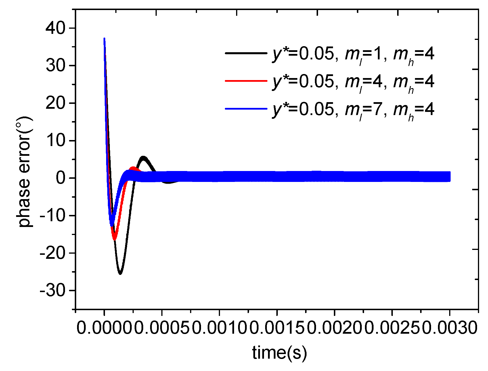
A few classical simulations are implemented to find the relationship between the performance of the nonlinear second-order PLL and the parameters of the nonlinear element. Moreover, on the basis of the relationship obtained from the simulation results, an algorithm is proposed to solve the optimal parameters of the nonlinear element N. The simulations are carried out as follows: a specific parameter of the nonlinear element is chosen to be three typical values while the other two parameters remain unchanged. First, the parameter ml selects as 1, 4, and 7 respectively, while y* is 0.05 and mh is 4. The simulation result is presented in Figure 4. Then, the parameter mh is chosen to be 1, 4, and 7 respectively, while the other two remains unchanged, the corresponding value of y* selects as 0 and ml as 1. And, the simulation result is shown in Figure 5. The other simulation parameters of the loop are: the eigenfrequency of the VCO is set ωo = 2π × 2 × 105 rad/s, the input angular frequency of the PLL is ωi = 2π × 1.99 × 105 rad/s, the input noise is ni = 0.01 × sin(1 × 10⁴ × t), and the gain of PD is Kd = 1 V. The LP parameters are τ1 = 500 × 10−6 and τ2 = 50 × 10−6. The sensitivity and sampling frequency of VCO are Ko = 1.3 × 10⁵ rad/(s V) and fs = 1 × 10⁶ Hz, respectively. The cut-off frequency of the LPF is α = 1 × 10⁶ Hz, and the simulation time is 3 ms.
As depicted in Figure 4 and Figure 5, the tracking speed of the PLL increases with ml and mh. In other words, the proposed PLL needs less time to achieve stable phase tracking (the phase error converges to zero) when the two parameters increase. However, the ability to suppress input noise deteriorations as the two parameters increase and the stable phase error jitters more intensely, which can be easily seen from Figure 4 and Figure 5.
The third parameter y* selects as 0, 0.05, and 0.5 respectively while ml is 1 and mh is 4. The simulation result is presented in Figure 6. It can be seen that the tracking speed of the PLL decreases when y* increases. Nevertheless, the ability to suppress the input noise is improved.
The three parameters are mutually constrained to jointly determine the comprehensive performance of the loop. On the basis of the analytical and simulation results, the fast locking performance is determined by the tracking speed and the noise reduction ability can be determined by the standard deviation of the frequency-phase error. Therefore, a new algorithm is proposed to solve the optimal parameters of the nonlinear element N. The final object function is constructed, which uses the minimum product of the locking time t*, namely the phase error when t ≥ t* is less than 30° and the standard deviation of the phase error as a target solution, as shown as in Equation (13).
The process of algorithm is as follows:
Step 1: In the numerical simulation process, dynamically select y* according to the output of the loop filter.
Step 2: Determine the dynamic range of the two segments slopes of the nonlinear element. In this paper, the settings of the dynamic range are mh (1, 10) and ml (0, 0.9).
Step 3: Calculate t* when the loop is locked, namely when phase_error(t ≥ t*) ≤ 30°, then calculate the standard deviation of the phase error.
Step 4: Calculate the object function based on the dynamic parameters of the nonlinear element.
Step 5: Repeat steps 1 through 4 and solve the object function, G = min(t*(y*,ml,mh) (phase_error(y*,ml,mh))).
The specific flow chart of the algorithm is shown in Figure 7.
With the above proposed algorithm, the calculated result of the object function in every iteration is stored in a three-dimensional matrix. In addition, the minimum value of the three-dimensional matrix corresponds to the optimal solution of the three parameters considering the comprehensive performance of the loop. Finally, with the parameters of the loop in this paper, the optimal parameters of the nonlinear element solved by the proposed algorithm are y* = 0.05, mh = 5, and ml = 1.5 respectively. The performance test results of the nonlinear second-order PLL are presented in Section 3.
3. Simulation and Results
The eigenfrequency of the VCO is set ωo = 2π × 2 × 105 rad/s, and the gain of PD is Kd = 1 V. The LP parameters are τ1 = 500 × 10−6 and τ2 = 50 × 10−6. The sensitivity and sampling frequency of VCO are Ko = 1.3 × 10⁵ rad/(s V) and fs = 1 × 10⁶ Hz, respectively. The cut-off frequency of the LPF is α = 1 × 10⁶ Hz, and the simulation time is 3 ms. The nonlinear PLL (NPLL) is evaluated under two conditions: NPLL1: y* = 0.05, ml = 1.5, mh = 5; and NPLL2: y* = 0, ml = 0, mh = 5. The second situation can be viewed as an extreme condition in which the nonlinear element is a linear amplification structure.
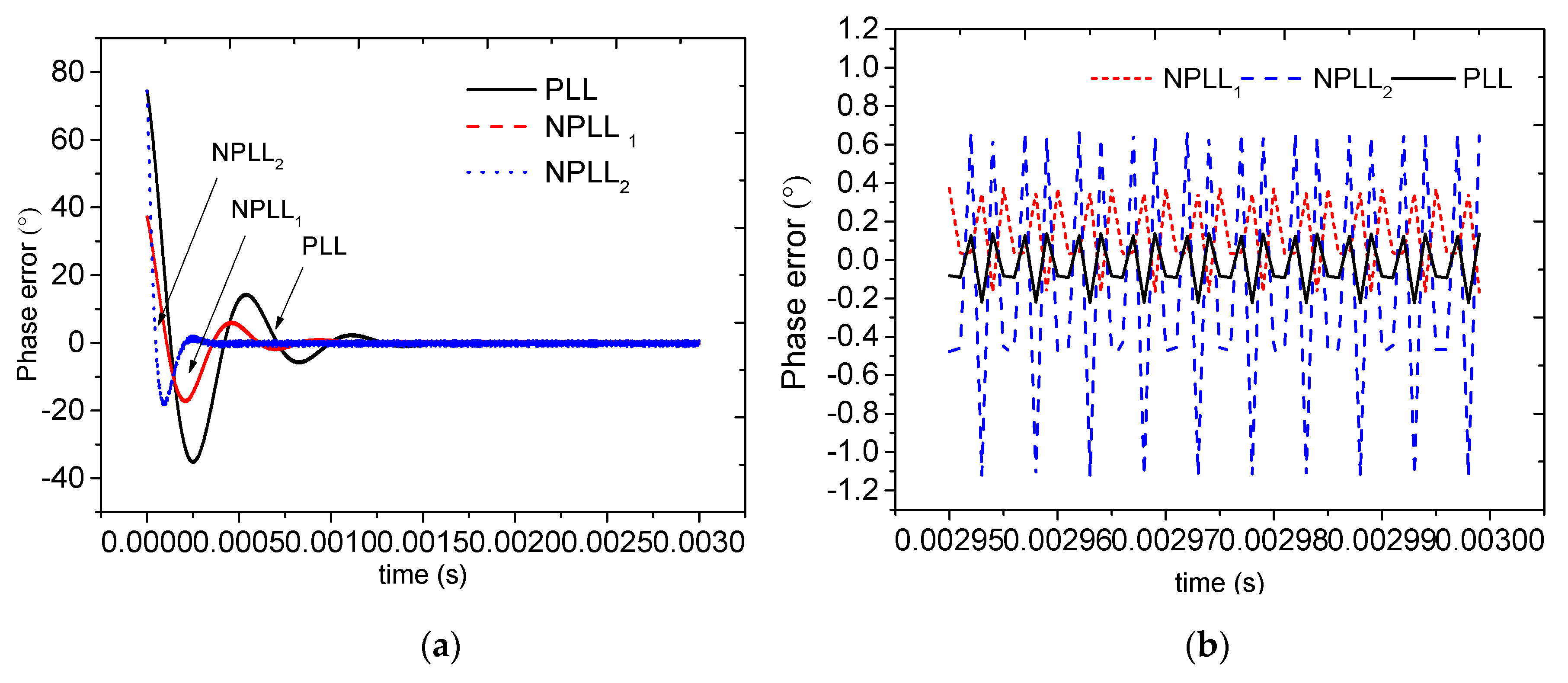
Test condition 1: the input angular frequency and the input noises are ωo = 2π × 2 × 105 rad/s and ni = 0.01 × sin(1 × 10⁴ × t). The input–output phase error of the new PLL under this condition is shown in Figure 8. It can be seen that NPLL1 and NPLL2 can be locked more quickly than the traditional PLL. Given that the NPLL2 is a linear amplification structure, it does not suppress noises through small ml in the end section, which determines its higher locking speed than that of NPLL1. In Figure 8b, the phase error of NPLL2 fluctuates considerably, which weakens the noise suppression capability. Therefore, the linear amplification structure fails to solve the contraction between tracking speed and accuracy fundamentally. However, the phase error fluctuation of NPLL1 is similar to that of the traditional PLL, indicating that NPLL1 suppresses noises successively through the compression of ml in the end section. Meanwhile, the tracking speeds of NPLL are increased by the amplification effect of mh. This condition realizes a compromise between the tracking speed and accuracy of the traditional PLL.
Test condition 2: the input angular frequency of the PLL is ωo = 2π × 1.99 × 105 rad/s. Under this condition, the input–output frequency offset of PLL is 1 kHz, and the input noise is ni = 0.01 × sin (1 × 10⁴ × t). The input–output phase error of PLL under this condition is shown in Figure 9.
Figure 9 shows that, when the input–output frequency offset is 1 kHz, NPLL1 and NPLL2 still can be locked more quickly than the traditional PLL. The phase error fluctuation amplitude of NPLL1 is equivalent to that of the traditional PLL, indicating the strong adaptation of the new PLL under large acquisition bandwidth.
Test condition 3: the input angular frequency of the PLL is ωo = 2π × 1.96 × 105 rad/s. Under this condition, the input–output frequency offset of the PLL is 4 kHz, and the input noise is ni = 0.01 × sin (1 × 10⁴ × t). The input–output phase error of the new PLL under this condition is shown in Figure 10.
Figure 10 shows that, when the input–output frequency offset is 4 kHz, the traditional PLL develops a cycle-skipping phenomenon. Meanwhile, the NPLL1 and NPLL2 still can be locked successfully, indicating the stronger adaption of new PLL to the large acquisition bandwidth than that of traditional PLL.
In order to detail what sets the upper boundary limit on the frequency difference, multiple sets of simulations are implemented. The frequency difference, namely ∆f, is set to be 6 kHz, 6.2 kHz, 6.3 kHz, and 6.4 kHz, respectively for NPLL1. The corresponding frequency of NPLL2 is 18.7 kHz, 18.8 kHz, 18.9 kHz, and 19 kHz, respectively. Finally, the maximum acquisition bandwidths of NPLL1 and NPLL2 are compared with those of the traditional PLL. The simulation results are shown in Figure 11.
As the input–output frequency offset increases from 4 kHz to 6 kHz and then to 6.2 kHz, NPLL1 still can be locked successfully (arrow line of NPLL1 in Figure 11). However, a cycle-skipping phenomenon is developed when the input–output frequency offset increases to 6.3 kHz and above. The acquisition bandwidth of NPLL1 is increased to 6.2 kHz from 4 kHz of the traditional PLL. When the input–output frequency offset is increased to 18.8 kHz, NPLL2 still can be locked successfully (arrow line of NPLL2 in Figure 11). However, a cycle-skipping phenomenon is developed when the input–output frequency offset equals 18.9 kHz and above. The acquisition bandwidth of NPLL2 is increased from 4 kHz to 18.8 kHz.
4. Discussion and Conclusions
This paper proposes a new second-order PLL structure coupled with one nonlinear element based on the nonlinear controlling idea. The proposed nonlinear second-order PLL conducts adaptive regulation of the loop bandwidth through the nonlinear element and balances between tracking speed and accuracy of traditional PLL. The results confirm that the new PLL not only can accelerate the tracking process, but also can increase the acquisition bandwidth by four times under some configuration of nonlinear element parameters compared with traditional PLL. The simulation results show the advantages of the new PLL. The proposed PLL changes the characteristics of the traditional second-order PLL itself to balance noise characteristics and fast locking performance. It will maintain good compatibility with the traditional communication systems because the proposal requires almost no additional cost. The improved PLL can be used to upgrade the traditional phase-locked receivers. The proposed new phase-locked loop will be able to adapt to large dynamic scenarios such as aerospace communications requisition and tracking, navigation, and energy harvest. Additionally, the proposal can be applied in cellular networks as well as real-time motion detection to improve the comprehensive performance of the modern communication networks. During practical applications in different fields, the parameters of the nonlinear components (e.g., turning point and slope) must be adjusted depending on the actual needs.
Author Contributions
L.Z. and C.Z. proposed research ideas and methods; C.Z. performed the simulations; L.S. analyzed the data; L.Z. wrote the paper.
Funding
This research was funded partly by the National Natural Science Foundation of China under Grants 61871302 & 61473228, National Defense Basic Scientific Research Program of China Grant CKY2016110C040, and Shaanxi National Natural Science Foundation under Grant 2016JM06.
Conflicts of Interest
The authors declare no conflict of interest.
References
- Anantharamu, P.B.; Borio, D.; Lachapelle, G. Sub-carrier shaping for BOC modulated GNSS signals. EURASIP J. Adv. Signal Process. 2011, 2011, 133. [Google Scholar] [CrossRef]
- Xue, W.; Shang, W.; Makarov, S.B.; Xu, Y. A phase trajectories optimization method for CPM signal based on Pan-function model. EURASIP J. Adv. Signal Process. 2016, 2016, 55. [Google Scholar] [CrossRef]
- Xu, R.; Liu, Z.; Chen, W. Improved FLL-assisted PLL with in-phase pre-filtering to mitigate amplitude scintillation effects. GPS Solut. 2015, 19, 263–276. [Google Scholar] [CrossRef]
- Golestan, S.; Guerrero, J.M.; Vasquez, J.C. High-Order Frequency-Locked Loops: A Critical Analysis. IEEE Trans. Power Electron. 2017, 32, 3285–3291. [Google Scholar] [CrossRef]
- Golestan, S.; Guerrero, J.M.; Vasquez, J.C. An Open-Loop Grid Synchronization Approach for Single-Phase Applications. IEEE Trans. Power Electron. 2018, 33, 5548–5555. [Google Scholar] [CrossRef]
- Kanjiya, P.; Khadkikar, V.; Moursi, M.S.E. A Novel Type-1 Frequency-Locked Loop for Fast Detection of Frequency and Phase with Improved Stability Margins. IEEE Trans. Power Electron. 2016, 31, 2550–2561. [Google Scholar] [CrossRef]
- Byun, S. More Discussions on Intrinsic Frequency Detection Capability of Full-Rate Linear Phase Detector in Clock and Data Recovery. Electronics 2018, 7, 93. [Google Scholar] [CrossRef]
- Kamel, T.; Abdelkader, D.; Said, B.; Padmanaban, S.; Iqbal, A. Extended Kalman Filter Based Sliding Mode Control of Parallel-Connected Two Five-Phase PMSM Drive System. Electronics 2018, 7, 14. [Google Scholar] [CrossRef]
- Kuznetsov, N.V.; Kuznetsova, O.A.; Leonov, G.A.; Neittaanm¨aki, P.; Yuldashev, M.V.; Yuldashev, R.V. Limitations of the classical phase-locked loop analysis. In Proceedings of the 2015 IEEE International Symposium on Circuits and Systems (ISCAS), Lisbon, Portugal, 24–27 May 2015; pp. 533–536. [Google Scholar]
- Kuznetsov, N.V.; Leonov, G.A.; Yuldashev, M.V.; Yuldashev, R.V. Hidden attractors in dynamical models of phase-locked loop circuits: Limitations of simulation in MATLAB and SPICE. Commun. Nonlinear Sci. Numer. Simul. 2017, 51, 39–49. [Google Scholar] [CrossRef] [Green Version]
- Chandra, T.M.; Debasmita, M.; Karabi, B.; Siddhartha, S. Design and performance study of phase-locked loop using fractional-order loop filter. Int. J. Circuit Theory Appl. 2015, 43, 776–792. [Google Scholar] [CrossRef]
- Katsinis, G.; Tsiropoulou, E.E.; Papavassiliou, S. A game theoretic approach to the power control in D2D communications underlay cellular networks. In Proceedings of the IEEE International Workshop on Computer Aided Modeling and Design of Communication Links and Networks, Athens, Greece, 1–3 December 2014; pp. 208–212. [Google Scholar]
- Katsinis, G.; Tsiropoulou, E.E.; Papavassiliou, S. Joint Resource Block and Power Allocation for Interference Management in Device to Device Underlay Cellular Networks: A Game Theoretic Approach. Mob. Netw. Appl. 2017, 22, 539–551. [Google Scholar] [CrossRef]
- Bravo-Muñoz, I.; Lázaro-Galilea, J.L.; Gardel-Vicente, A. FPGA and SoC Devices Applied to New Trends in Image/Video and Signal Processing Fields. Electronics 2017, 6, 25. [Google Scholar] [CrossRef]
- Singh, S.; Shekhar, C.; Vohra, A. FPGA-Based Real-Time Motion Detection for Automated Video Surveillance Systems. Electronics 2016, 5, 10. [Google Scholar] [CrossRef]
- Choukri Benhabib, M.; Saadate, S. A New Robust Experimentally Validated Phase Locked Loop for Power Electronic Control. EPE J. 2005, 15, 36–48. [Google Scholar] [CrossRef]
- Humphreys, T.E.; Psiaki, M.L.; Kintner, P.M. GPS Carrier Tracking Loop Performance in the presence of Ionospheric Scintillations. In Proceedings of the 18th International Technical Meeting of the Satellite Division of The Institute of Navigation, Long Beach, CA, USA, 13–16 September 2005. [Google Scholar]
- Ganguly, S.; Jovancevic, A.; Brown, A.; Kirchner, M.; Zigic, S.; Beach, T.; Groves, K.M. Ionospheric scintillation monitoring and mitigation using a software GPS receiver. Radio Sci. 2004, 39, 1–9. [Google Scholar] [CrossRef]
- Kiesel, S.; Ascher, C.; Gramm, D.; Trommer, G.F. GNSS receiver with vector based FLL-assisted PLL carrier tracking loop. In Proceedings of the ION GNSS, Savannah, GA, USA, 16–19 September 2008; pp. 197–203. [Google Scholar]
- Cupertino, F.; Lavopa, E.; Zanchetta, P.; Sumner, M.; Salvatore, L. Running DFT-Based PLL Algorithm for Frequency, Phase, and Amplitude Tracking in Aircraft Electrical Systems. IEEE Trans. Ind. Electron. 2011, 58, 1027–1035. [Google Scholar] [CrossRef]
- Legrand, F.; Macabiau, C.; Issler, J.-L.; Lestarquit, L.; Mehlen, C. Improvement of pseudorange measurements accuracy by using fast adaptive bandwidth lock loops. Proceedings of 13th International Technical Meeting of the Satellite Division of The Institute of Navigation (ION GPS 2000), Salt Lake City, UT, USA, 19–22 September 2000; pp. 2346–2356. [Google Scholar]
- Legrand, F.; Macabiau, C. Results of the implementation of the fast adaptive bandwidth lock loops on a real GPS receiver in a high dynamics context. In Proceedings of the International Conference on Global Navigation Satellite System (GNSS 2001), Seville, Spain, 8–11 May 2001. [Google Scholar]
- Vaucher, C.S. An adaptive PLL tuning system architecture combining high spectral purity and fast settling time. IEEE J. Solid-State Circuits 2000, 35, 490–502. [Google Scholar] [CrossRef] [Green Version]
- Ulvgård, L.; Kamf, T.; Leijon, M. Offshore Measurement System for Wave Power—Using Current Loop Feedback. Electronics 2016, 5, 86. [Google Scholar] [CrossRef]
Figure 1.
(a) Basic structure of the second-order phase-locked loop (PLL). (b) Model of the second-order PLL.
Figure 1.
(a) Basic structure of the second-order phase-locked loop (PLL). (b) Model of the second-order PLL.

Figure 2.
Basic structure of the new nonlinear second-order PLL.
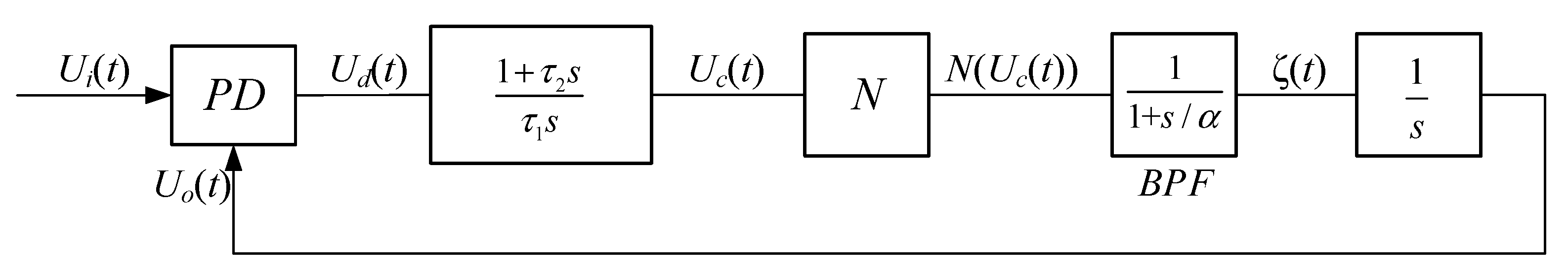
Figure 3.
Schematic of three-stage nonlinear element.
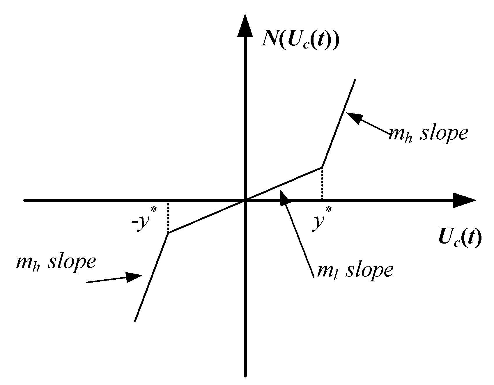
Figure 4.
Phase error when ml changes.

Figure 5.
Phase error when mh changes.
Figure 6.
Phase error when y* changes.

Figure 7.
Flow chart of the algorithm.
Figure 8.
Phase error of PLL under no frequency offset: (a) phase error of PLL under no frequency offset; (b) phase error of PLL after 2.95 ms.
Figure 8.
Phase error of PLL under no frequency offset: (a) phase error of PLL under no frequency offset; (b) phase error of PLL after 2.95 ms.

Figure 9.
Phase error of PLL under a frequency offset of 1 KHZ: (a) phase error of PLL under a frequency offset of 1 kHz; (b) phase error of PLL after 2.95 ms.
Figure 9.
Phase error of PLL under a frequency offset of 1 KHZ: (a) phase error of PLL under a frequency offset of 1 kHz; (b) phase error of PLL after 2.95 ms.

Figure 10.
Phase error of PLL under a frequency offset of 4 kHz: (a) Phase error of PLL under a frequency offset of 4 kHz; (b) Phase error of PLL after 2.95 ms.
Figure 10.
Phase error of PLL under a frequency offset of 4 kHz: (a) Phase error of PLL under a frequency offset of 4 kHz; (b) Phase error of PLL after 2.95 ms.
Figure 11.
Phase error of PLL under different frequency offsets.

© 2018 by the authors. Licensee MDPI, Basel, Switzerland. This article is an open access article distributed under the terms and conditions of the Creative Commons Attribution (CC BY) license (http://creativecommons.org/licenses/by/4.0/).
Share and Cite
MDPI and ACS Style
Zhao, L.; Shi, L.; Zhu, C. New Nonlinear Second-Order Phase-Locked Loop with Adaptive Bandwidth Regulation. Electronics 2018, 7, 346. https://doi.org/10.3390/electronics7120346
AMA Style
Zhao L, Shi L, Zhu C. New Nonlinear Second-Order Phase-Locked Loop with Adaptive Bandwidth Regulation. Electronics. 2018; 7(12):346. https://doi.org/10.3390/electronics7120346
Chicago/Turabian StyleZhao, Lei, Lei Shi, and Congying Zhu. 2018. "New Nonlinear Second-Order Phase-Locked Loop with Adaptive Bandwidth Regulation" Electronics 7, no. 12: 346. https://doi.org/10.3390/electronics7120346
Note that from the first issue of 2016, this journal uses article numbers instead of page numbers. See further details here.