A Novel Composite Equalizer Based on an Additional Cell for Series-Connected Lithium-Ion Cells


College of Mechanical Engineering, University of Shanghai for Science and Technology, Shanghai 200093, China
*
Authors to whom correspondence should be addressed.
Electronics 2018, 7(12), 366; https://doi.org/10.3390/electronics7120366
Submission received: 1 October 2018
/
Revised: 20 November 2018
/
Accepted: 20 November 2018
/
Published: 1 December 2018
(This article belongs to the Special Issue Applications of Power Electronics)
Abstract
:Cell inconsistency can lead to poor performance and safety hazards. Therefore, cell equalizer is essentially required to prevent the series-connected cells from overcharging, undercharging, and overdischarging. Among current equalization schemes, passive equalizer has a continuously wasting energy with low equalization efficiency, and active equalizer has high cost with complex circuit structure. In this study, a novel composite equalizer based on an additional cell with low complexity is presented. This method combines a passive equalizer and an active equalizer. Firstly, the configuration and circuit of our proposed composite equalizer are introduced, and the equalization principle is analyzed. On this basis, the control strategy and algorithm of the composite equalizer are further proposed. Finally, the composite equalizer is verified through simulation and experiment in various cases. The study results show that this method improves both the consistency level and the available capacity of the battery pack. Moreover, our proposed equalizer can overcome the shortcomings of commonly used equalizer and combining the advantages of different equalizer to maximize the equalization efficiency with a simpler equalizer structure.
1. Introduction
Energy crisis and environmental problem are two major challenges facing humankind in recent years, and energy savings and emission reduction have become real priorities all over the world. New technologies and methods for saving energy and reducing emissions have become an important research focus in modern automobiles [1,2,3,4,5]. In this situation, the development and popularization of battery electric vehicles (BEVs) and hybrid electric vehicles (HEVs) have entered a high-speed period. As energy storage and supply components, batteries directly determine the safety and mileage of electric vehicles (EVs). Therefore, battery and its management system are one of the core technologies of EVs [6,7,8]. Various power batteries, such as lead acid, nickel-metal hydride (NiMH), and lithium-ion batteries (LIBs) have been used in EVs. Among them, LIBs are widely used due to their high energy density, long cycle life, and high efficiency [4,9,10,11]. In order to meet high-energy and high-power application requirements for EVs, hundreds or thousands of cells are connected in series and parallel to form battery packs [12,13,14]. Factors such as the manufacturing process and the actual working environment cause inconsistencies in the performance of these LIBs. The most intuitive manifestation is voltage inconsistency, while the other is internal resistance inconsistency. These inconsistencies cause the actual capacity of the battery packs to be less than the theoretical capacity, which greatly reduces their service life [5,15,16,17].
In order to reduce cell inconsistency, it is necessary to screen cells before combining them into a battery pack. Cells in the same battery pack should have the same chemical properties and physical sizes. However, the consistency level among cells is already higher even after screening. Cell inconsistency in a battery pack can lead a cell or some cells to be overcharged, undercharged, or even overdischarged, causing serious security problems [5,16,18]. In order to maximize battery life and utilization, battery equalization technology is widely used to reduce the impact of battery inconsistencies. Therefore, equalization technology is critical for improving battery performance.
There are two main ways to equalize lithium-ion batteries. One is chemical equalization, i.e., to achieve an equalization target through the chemical reaction inside the battery [19]. This method is easy to implement and does not require complex circuit connections, but this method is presently in its infancy. The other is physical equalization, i.e., to achieve an equalization target by means of mechanics or electronics. Physical equalization mainly includes passive and active equalization [20,21]. Passive equalization, also known as energy dissipation equalization, can realize equalization by passing the excess energy of the cell through a bypass resistor. Passive equalization is advantageous in terms of its simple structure and low cost, but is disadvantageous due to its low equalization current and large energy loss [22,23,24]. However, energy is dissipated in the form of heat by the bypass resistor, which greatly reduces the energy utilization of the whole battery and simultaneously increases the temperature. Due to the demands of controlling the temperature within a certain range, the equalization current is usually low and the equalization time is long. In addition, the temperature difference may worsen the battery inconsistency [25].
Active equalization, also called energy transfer equalization, can realize energy transfer between cells in the battery packs by means of energy storage elements or other driving circuit configurations. Various active equalization configurations are summarized in Refs. [26,27,28]. The common energy storage elements are capacitors, inductors, and transformers. The advantages of active equalization include low energy loss and high efficiency. However, the disadvantages include complex control algorithms and high cost. In addition to the equalization configuration, the equalization algorithm also has a significant impact on the equalization efficiency improvement. It can be divided into state of charge (SOC)-, capacity-, and voltage-based equalization algorithms [22,29,30,31]. Generally, the energy transfer between the cells is a function of the voltage difference between cells. As a result, when the voltage difference is low, the equalization speed decreases and cells can remain unbalanced [22,30,32], and the balancing efficiency needs to be further improved [33]. Through the analysis above, we know that both active and passive equalizers have their own advantages and disadvantages.
In this study, a novel composite equalization method based on an additional cell which combines both passive and active equalizations is proposed, according to the characteristics of different equalization methods. The principle, circuit, and control strategy and algorithm are studied, and the effectiveness is verified by simulation in various cases. This method has the advantages of simple structure, low cost, simple control, and high efficiency compared to common passive and active equalization methods. Moreover, an additional cell is used in this method as the energy storage element, which allows energy storage and transfer between the battery and the additional cell. This increases the capacity of the battery pack to a certain degree while also realizing the equalization function.
The remainder of this paper is structured as follows: Section 2 gives a description of the circuit of the composite equalization. Section 3 presents its operation principles and control strategy, respectively. Modeling and simulation analysis are reported in Section 4. The effectiveness of the proposed equalizer is validated by experimental results in Section 5. Finally, conclusions and final remarks are presented in Section 6.
2. Scheme of Composite Equalizer
2.1. Configuration of the Composite Equalization Circuit
To improve the equalization efficiency, we propose a composite equalization configuration based on an additional cell that combines both passive and active equalization. This method makes full use of the advantages of different equalizations, as shown in Figure 1a. The equalization circuit is primarily composed of the main controller, the voltage acquisition module, the composite equalization module, and so on.
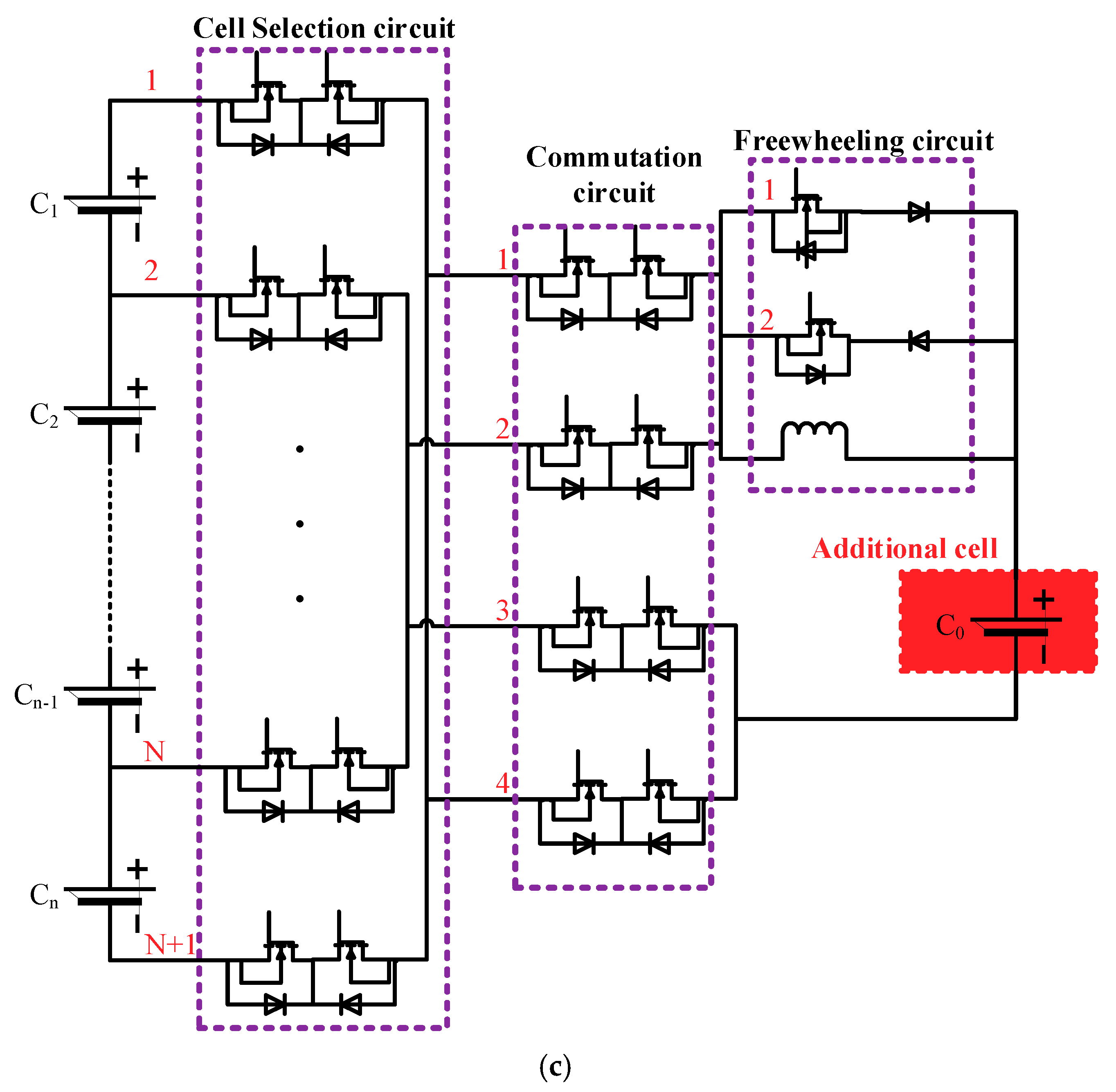
Recently, the widely used passive equalization method uses a bypass resistor in parallel with the cell to consume the excess energy of the cell, as shown in Figure 1b. The active equalization in this paper uses an additional cell as the energy storage element, thus allowing for energy storage and transfer between the battery and the additional cell. This increases the capacity of the battery pack to a certain degree while also enabling the equalization function. As shown in Figure 1c, the active equalization circuit mainly includes a cell selection circuit, a commutation circuit, a freewheeling circuit, and so on. The cell selection circuit is used to select the cell to be equalized in the battery pack. The function of the commutation circuit is to make the positive and negative polarity of the cell which is to be equalized the same as the additional cell. The circuit includes four parallel branches. The freewheeling circuit consists of diodes, MOSFETs, and an inductor, and is used to buffer the current of the circuit and protect the circuit elements from being damaged when the circuit is switched on or off.
2.2. Principle of the Composite Equalization Circuit
The basic principle of composite equalization is to choose the best equalization mode according to the relative voltage state between the cell in the battery pack and the additional cell. Equalization modes are generally divided into active and passive equalization modes. The active equalization mode can also be divided into the first and second active equalization modes. The equalization modes are explained separately as follows: (a) First active equalization mode: the high voltage cell charges the additional cell when this mode is in operation. As shown in Figure 2a, it is assumed that C1 is the cell with the maximum voltage in the battery pack. The corresponding MOSFETs are controlled to turn on, and C1 then charges the additional cell C0. (b) Second active equalization mode: the additional cell charges the low voltage cell when this mode is in operation. As shown in Figure 2b, it is assumed that C2 is the cell with the minimum voltage in the battery pack. The corresponding MOSFETs are controlled to turn on, and the additional cell C0 then charges C2. (c) Passive equalization mode: the high voltage cell battery is discharged through the bypass resistor when this mode is in operation. As shown in Figure 2c, it is assumed that C1 is the cell with the maximum voltage in the battery pack. The corresponding MOSFETs are controlled to turn on and C1 is then discharged through the bypass resistor. Therefore, through designing the control strategy and algorithm, each of the three equalization modes is activated according to the cell voltage change during the equalization process.
3. Control Strategy and Algorithm
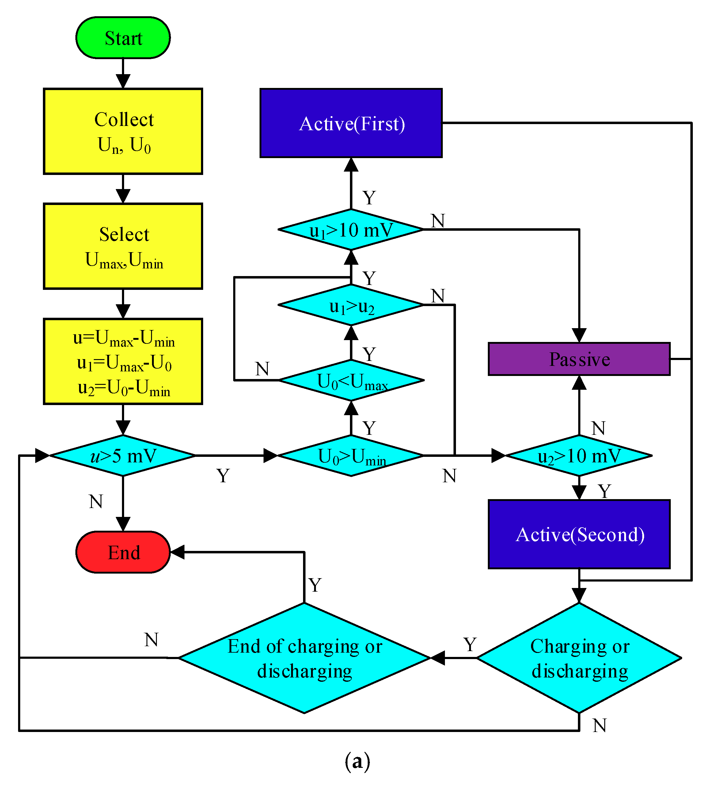
The voltage-based equalization algorithm is adopted in this paper. First, a threshold of voltage range (5 mV in this paper) is chosen. Then the voltages of cells in the battery pack are collected, and the maximum and minimum voltage are selected. If the difference between the maximum and minimum voltage is greater than the threshold, equalization control will be applied to the battery pack, otherwise not.
We first need to determine the critical voltage difference value ∆U between the additional cell and the cell to be equalized in the battery pack. When the active and passive equalization currents are equal, the voltage difference between the cell to be equalized in the battery pack and the additional cell is equal to the critical value ∆U.
It is assumed that the voltage of the cell i is Ui, where i = 1, 2, 3, …, n. The maximum voltage is Umax, and the minimum voltage is Umin. The voltage range between the cells is u. The voltage of the additional cell is U0. The difference between the maximum voltage and the additional cell voltage is u1. The difference between the additional cell voltage and the minimum voltage is u2. The relationship between these parameters can be expressed as follows:
Based on the analysis above, the composite equalization control algorithm designed in this paper is shown in Figure 3a, and can be specifically described as:
- (1)
- When the voltage U0 of the additional cell C0 is detected to be less than the minimum voltage Umin in the battery pack and u1 is greater than ∆U, the first active equalization mode is used. Otherwise, passive equalization is used.
- (2)
- When the voltage U0 of the additional cell C0 is detected to be greater than the maximum voltage Umax in the battery pack and u2 is greater than ∆U, the second active equalization mode is used. Otherwise passive equalization is used.
- (3)
- When the voltage U0 of the additional cell C0 is between the minimum voltage Umin and the maximum voltage Umax and u1 is greater than u2, return to (1). Otherwise, return to (2).
- (4)
- When the battery pack is charged or discharged (dynamic equalization), equalization will stop once charging or discharging has completed. When the battery pack is not charged or discharged (static equalization), equalization will stop if the difference between the maximum and the minimum voltage in the battery pack is less than the threshold (5 mV in this paper).
The passive equalization control algorithm is shown in Figure 3b. To avoid frequent activation of the switches, the cell’s single equalization time T must reach t0. The active equalization control algorithm is shown in Figure 3c. To avoid frequent activation of the switches, the cell’s single equalization time T must reach t0. The switch of the cell selection circuit is turned off immediately when the active equalization current IL is greater than 2 A, thus suspending equalization. When the active equalization current IL is less than 1 A, the switch is turned on to continue equalization. In dynamic equalization, t0 should not be large; we take 60 s in this paper. In static equalization, t0 should not be too small; we take 600 s in this paper.
4. Modeling and Simulation Analysis
In this section, we use the Simscape module in MATLAB/Simulink (MathWorks, Natick, MA, USA) to build a physical model of the composite equalization circuit, and we model the equalization control strategy and algorithm in Simulink/Stateflow. The simulation model is shown in Figure 4. Based on the simulation model, the equalization process is simulated in various cases, to verify the effectiveness of the proposed composite equalization.
The parameters set in the simulation are as follows: four lithium-ion cells with nominal voltage 3.7 V and rated capacity 24 Ah are connected in series to form a battery pack. The additional cell is also a lithium-ion cell with nominal voltage 3.7 V and rated capacity 24 Ah. The resistance of the bypass resistor is 30 Ω. According to the control strategy in the last section, we need to determine the size of ∆U. Preliminary simulation results show that the size of passive equalization current is 0.13 A. When the active equalization current reaches 0.13 A, the voltage difference between the additional cell and the cell which is being equalized in the battery pack is about 10 mV, thus the size of ∆U is 10 mV. The equalization process is simulated under three different states named charging, discharging and static to verify the effectiveness of the proposed composite equalization method. Simulation is carried out in MATLAB 2014a on a computer with a 3.1 GHz processor, 4 GB memory, and 64-bit operating system.
4.1. Equalization during the Charging Process
During the entire charging equalization process, there are three different conditions on the relative voltage state between the cell to be equalized in the battery pack and the additional cell, which are described as follows:
- (1)
- The relative voltage state between the cell to be equalized in the battery pack and the additional cell stays constant, and the voltage U0 of the additional cell is always less than the minimum voltage Umin.
- (2)
- The relative voltage state between the cell to be equalized in the battery pack and the additional cell undergoes a dynamic change process. At first, the voltage U0 of the additional cell is greater than the maximum voltage Umax. Then it takes a value between the minimum voltage Umin and the maximum voltage Umax. Finally, it is less than the minimum voltage Umin.
- (3)
- The relative voltage state between the cell to be equalized in the battery pack and the additional cell stays constant, and the voltage U0 of the additional cell is always greater than the maximum voltage Umax.
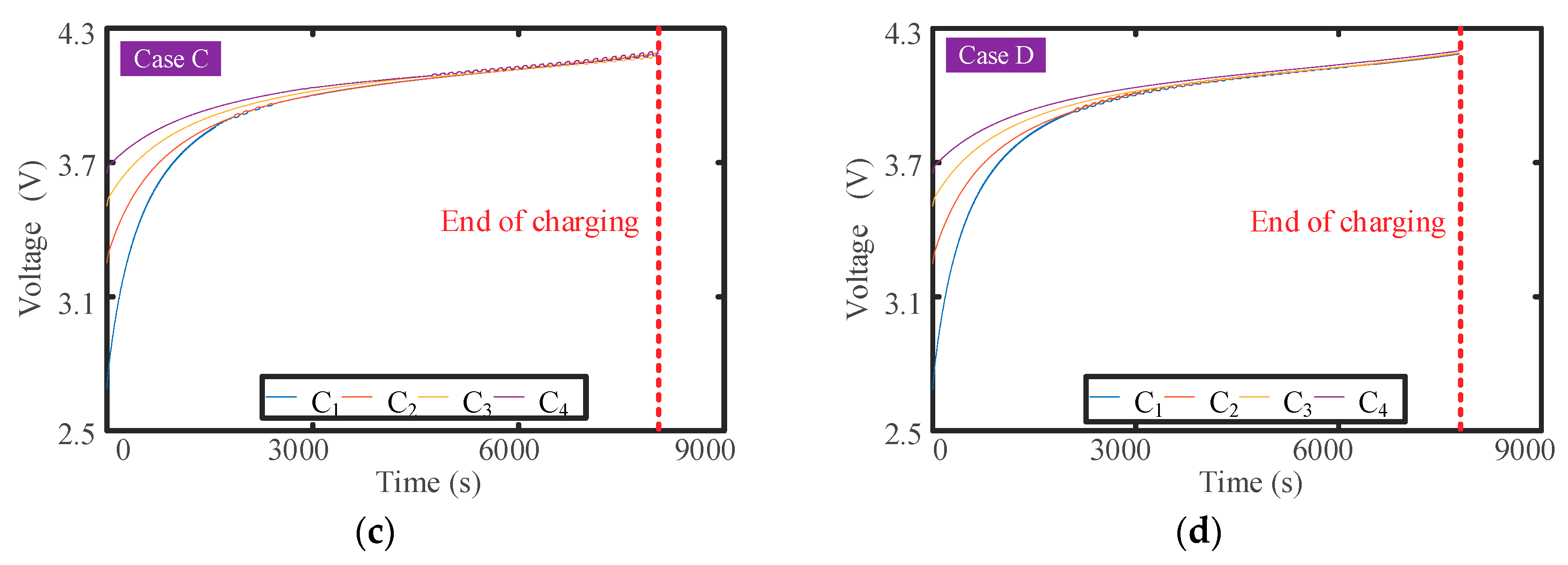
Assuming that the SOC of C1 to C4 are set to 5%, 8%, 11%, and 14%, respectively. Before charging, the SOC of the additional cell is set to 2%, 50%, and 98% under the three conditions above, respectively. A constant current power supply with 8 A of current is used to charge the battery pack. When the voltage of any cell in the battery pack reaches 4.2 V, the constant current power supply will stop charging the battery pack.
In this study, four cases marked as case A, B, C, and D are set to simulate the equalization effect under charging conditions, and the simulation results are shown in Figure 5 and Table 1. As shown in Figure 5, the voltage difference among cells during the charging process without equalization is 43.20 mV, but it decreases to 27.50 mV, 27.70 mV, and 14.20 mV after equalization.
As shown in Table 1, the charging time increases when charging with equalization, indicating that the capacity of the battery pack increases after charging with equalization. Our previous studies [33,34] show the relationship between pack capacity and cell capacities is:
where Cpack is pack capacity, SOC is the state of charge of the cell, and C is the cell capacity.
4.2. Equalization during the Discharging Process
During the entire discharging equalization process, there are three different conditions on the relative voltage state between the cell to be equalized in the battery pack and the additional cell, which are as follows:
- (1)
- The relative voltage state between the cell to be equalized in the battery pack and the additional cell stays constant, and the voltage U0 of the additional cell is always less than the minimum voltage Umin.
- (2)
- The relative voltage state between the cell to be equalized in the battery pack and the additional cell undergoes a dynamic change process. At first, the voltage U0 of the additional cell is less than the minimum voltage Umin. Then, it takes a value between the minimum voltage Umin and the maximum voltage Umax. Finally, it is greater than the maximum voltage Umax.
- (3)
- The relative voltage state between the cell to be equalized in the battery pack and the additional cell stays constant, and the voltage U0 of the additional cell is always greater than the maximum voltage Umax.
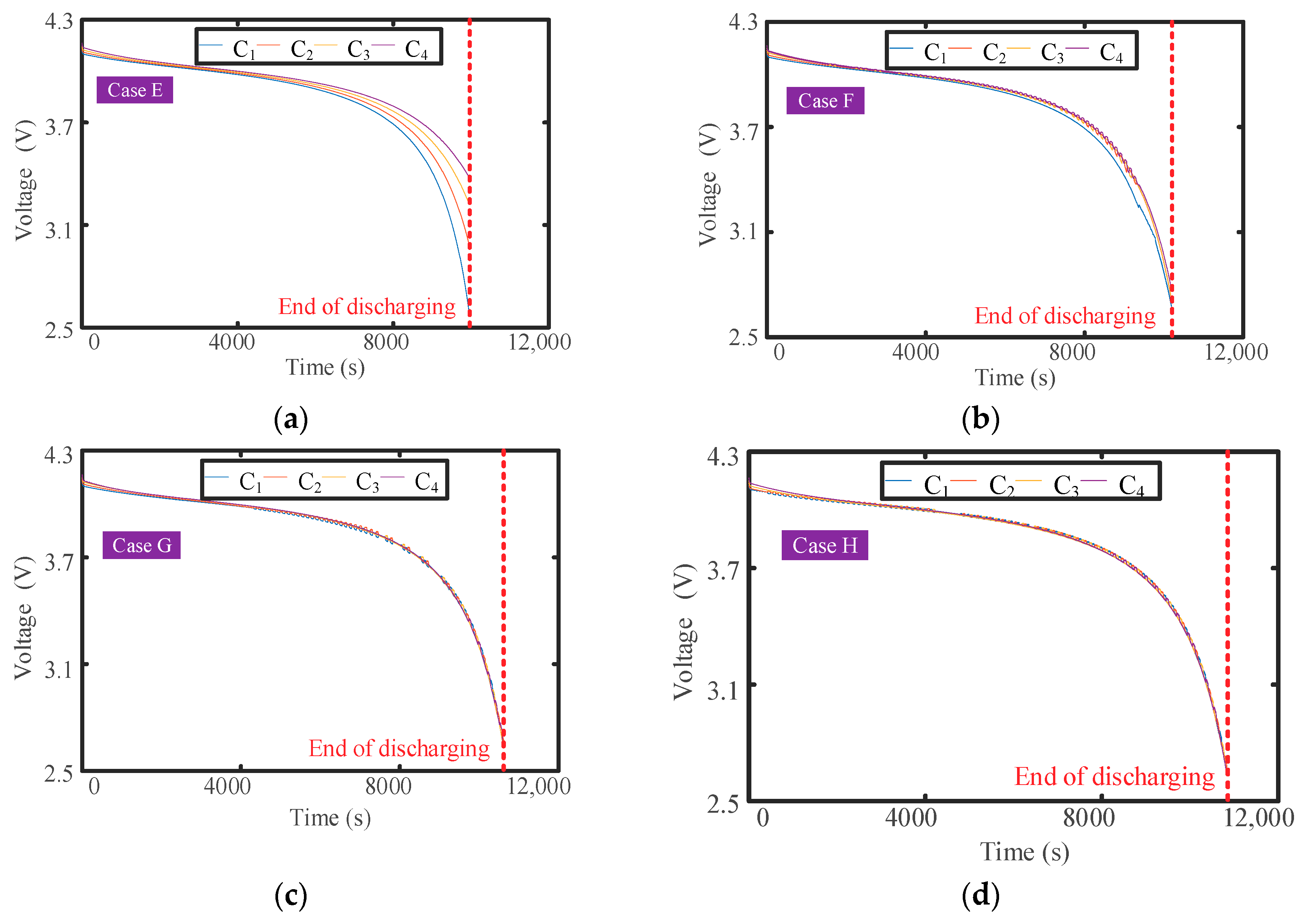
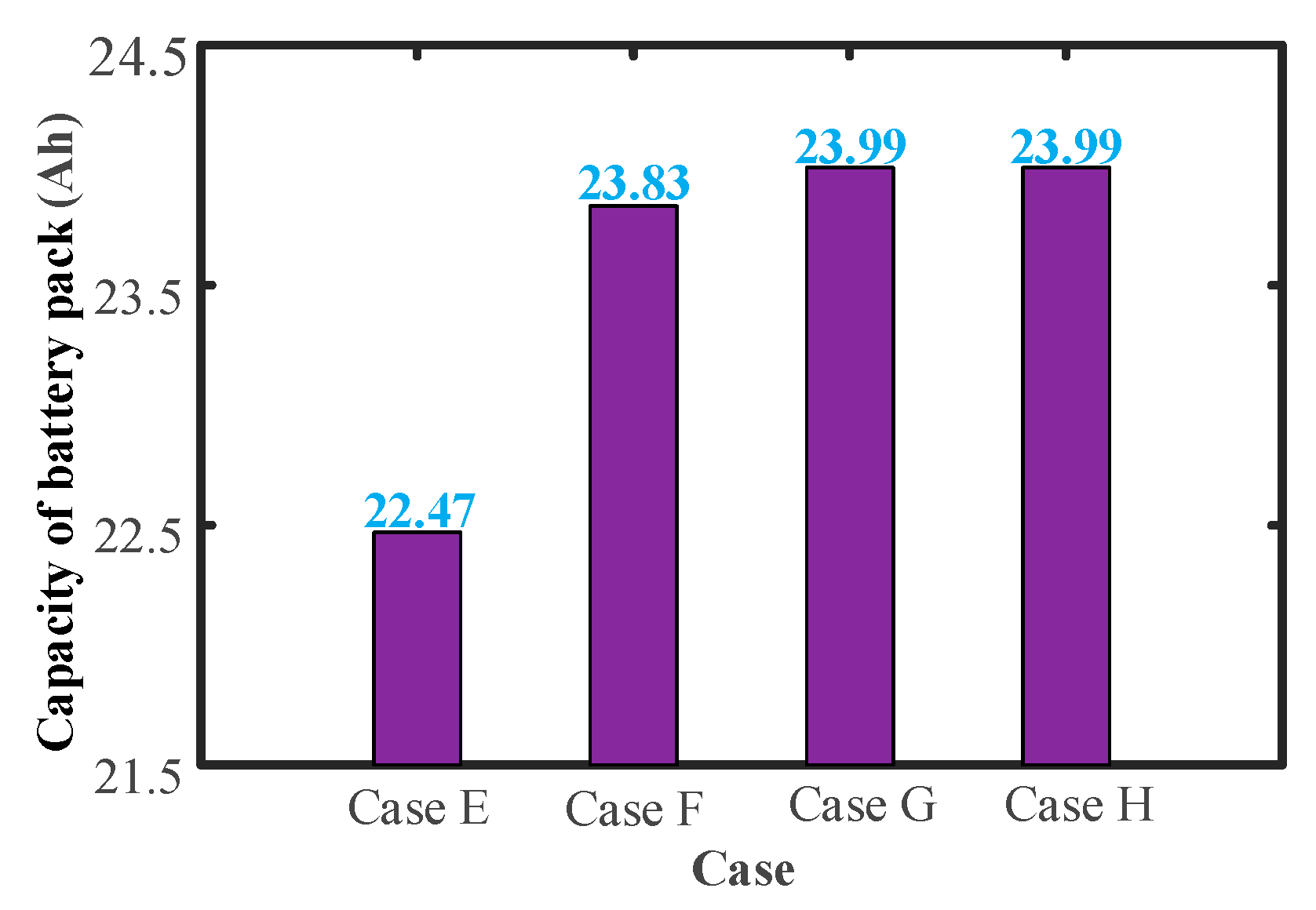
Assuming that the SOC of C1–C4 is set to 90%, 92%, 94%, and 96%, respectively, before discharging, the SOC of the additional cell is set to 2%, 50%, and 98%, respectively, under the three conditions above. A 2 Ω resistor is used to discharge the battery pack. When the voltage of any cell in the battery pack reaches 2.6 V, the battery pack will stop discharging. The voltage change trajectory of the cells in the battery pack is shown in Figure 7 and the discharging time is shown in Table 3. As shown in Figure 7, the voltage difference among cells during the discharging process without equalization is 789.10 mV, but it decreases to 95.10 mV, 40.30 mV, and 21.80 mV after equalization.
4.3. Equalization during the Static Process
During the entire static equalization process, the relative voltage state between the cell to be equalized in the battery pack and the additional cell stays constant. There are three different conditions, which are as follows:
- (1)
- The voltage U0 of the additional cell is always less than the minimum voltage Umin.
- (2)
- The voltage U0 of the additional cell is always between the minimum voltage Umin and the maximum voltage Umax.
- (3)
- The voltage U0 of the additional cell is always greater than the maximum voltage Umax.
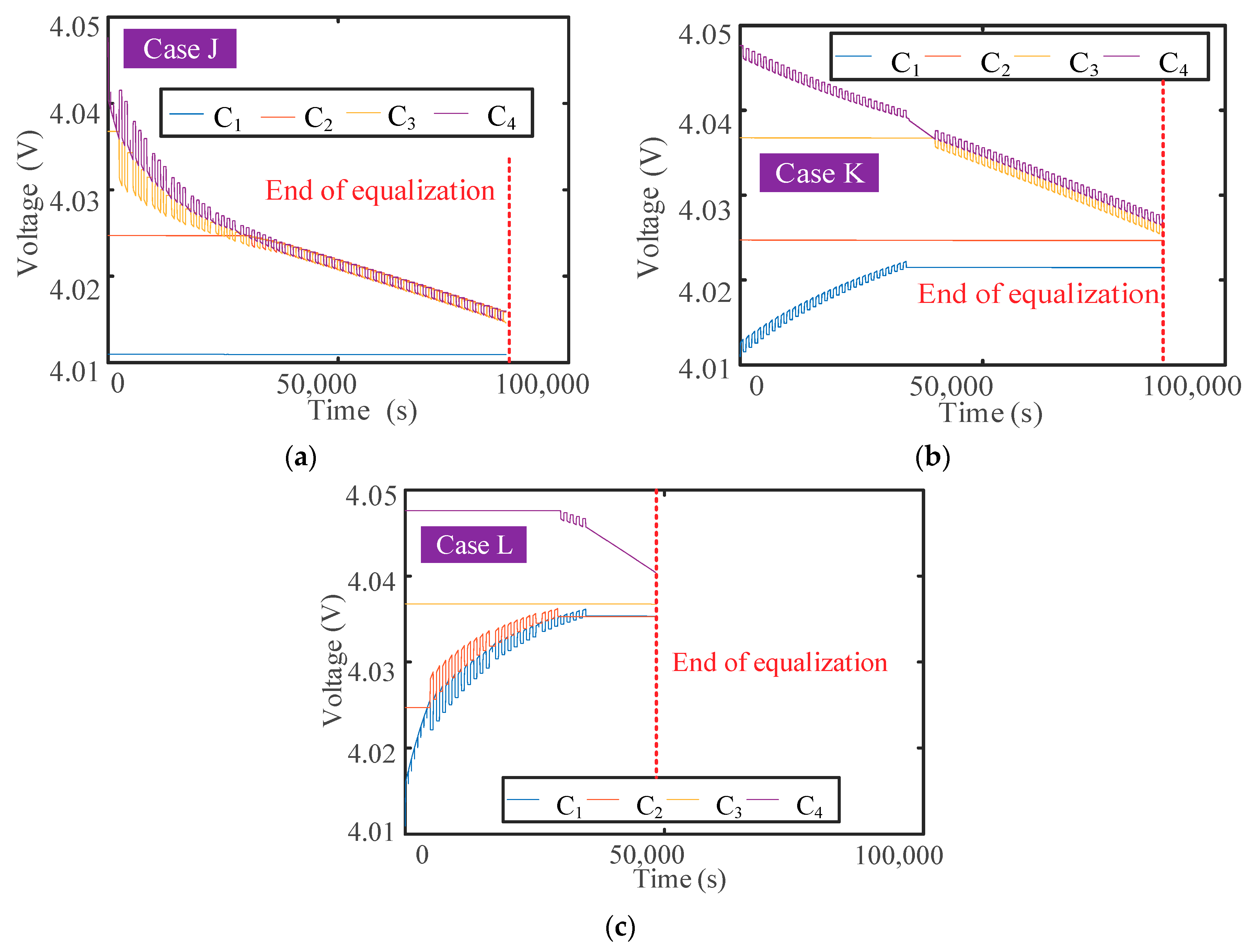
Assuming that the SOC of C1–C4 is set to 46%, 50%, 54%, and 58%, respectively, the SOC of the additional cell is set to 36%, 52%, and 68% under the three conditions above, respectively. Equalization will only begin if the voltage range of the cells in the battery pack is greater than 5 mV. The voltage change trajectory of the cells in the battery pack is shown in Figure 9, and the discharging time is shown in Table 5. As shown in Figure 9, the voltage difference among cells without equalization is 36.60 mV, but it decreases to about 5 mV after equalization.
4.4. Comparative Study with Passive and Active Equalization
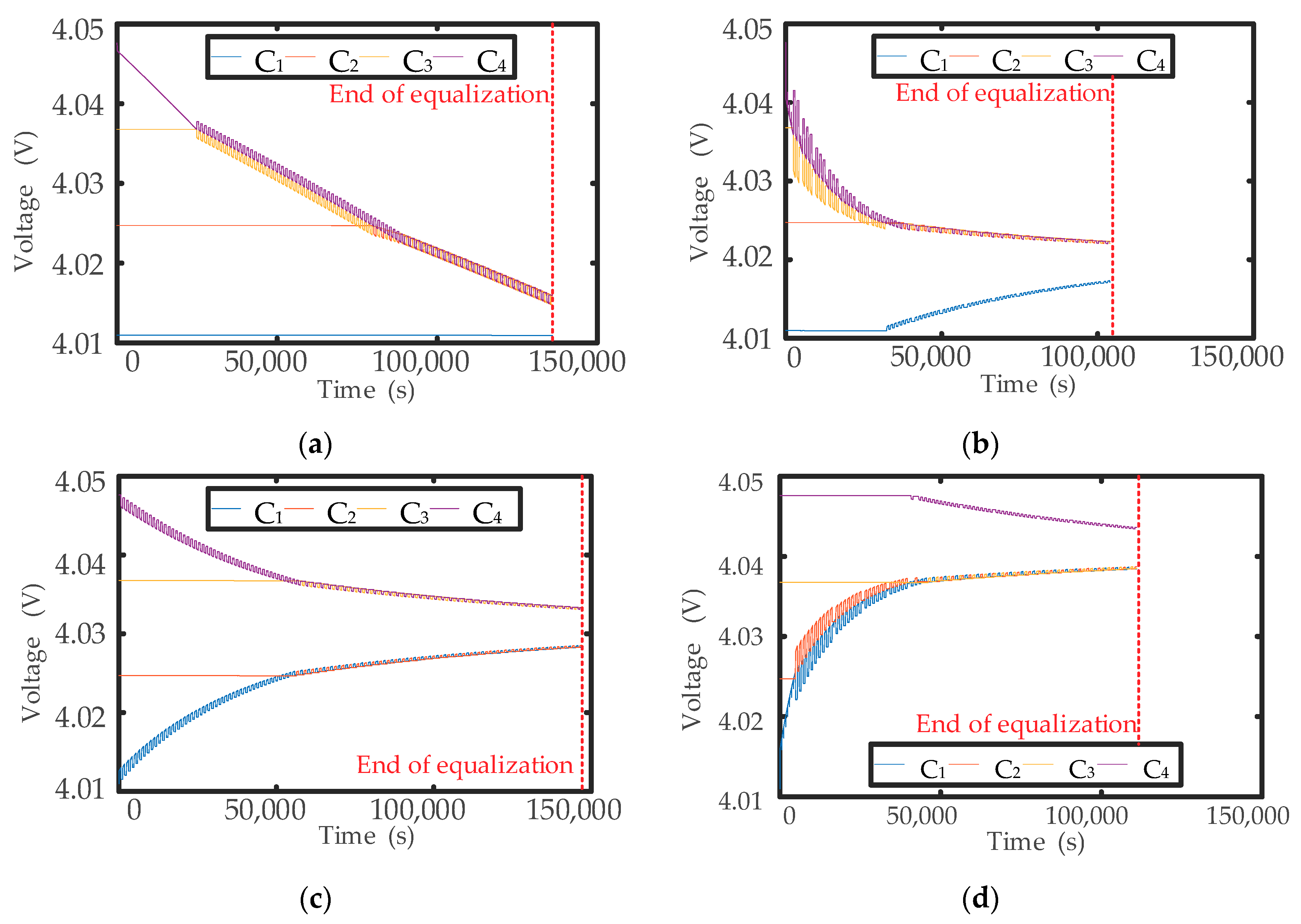
In this section, the composite equalization is compared to the passive and active equalization introduced in Section 2. We only choose the equalization during the static process in this section. The equalization during other process (charge and discharge) is similar, so there is no detail. Therefore, the initial conditions of cells in this section is consistent with that in Section 4.3. As for the comparison results, the end voltage and capacity of the cells are not very different because the equalization target (5 mV) of different equalizers are the same. In the previous sections, the end voltage and capacity of the cells are used to compare results between no equalization and equalization, so the comparison in this section is mainly through the equalization time. The shorter the equalization time, the better the equalization effect.
The voltage change of the cells in the battery pack during the different equalization methods is shown in Figure 11, and the equalization time of the different equalization methods is listed in Figure 12. It can be seen that the equalization time of the active and passive equalizers is longer than that of the proposed composite equalizer in the case of the additional cell with various SOCs, indicating the proposed method has higher equalization efficiency. Moreover, the equalization efficiency increases with the increase of the SOC of the additional cell.
5. Experiment Verification
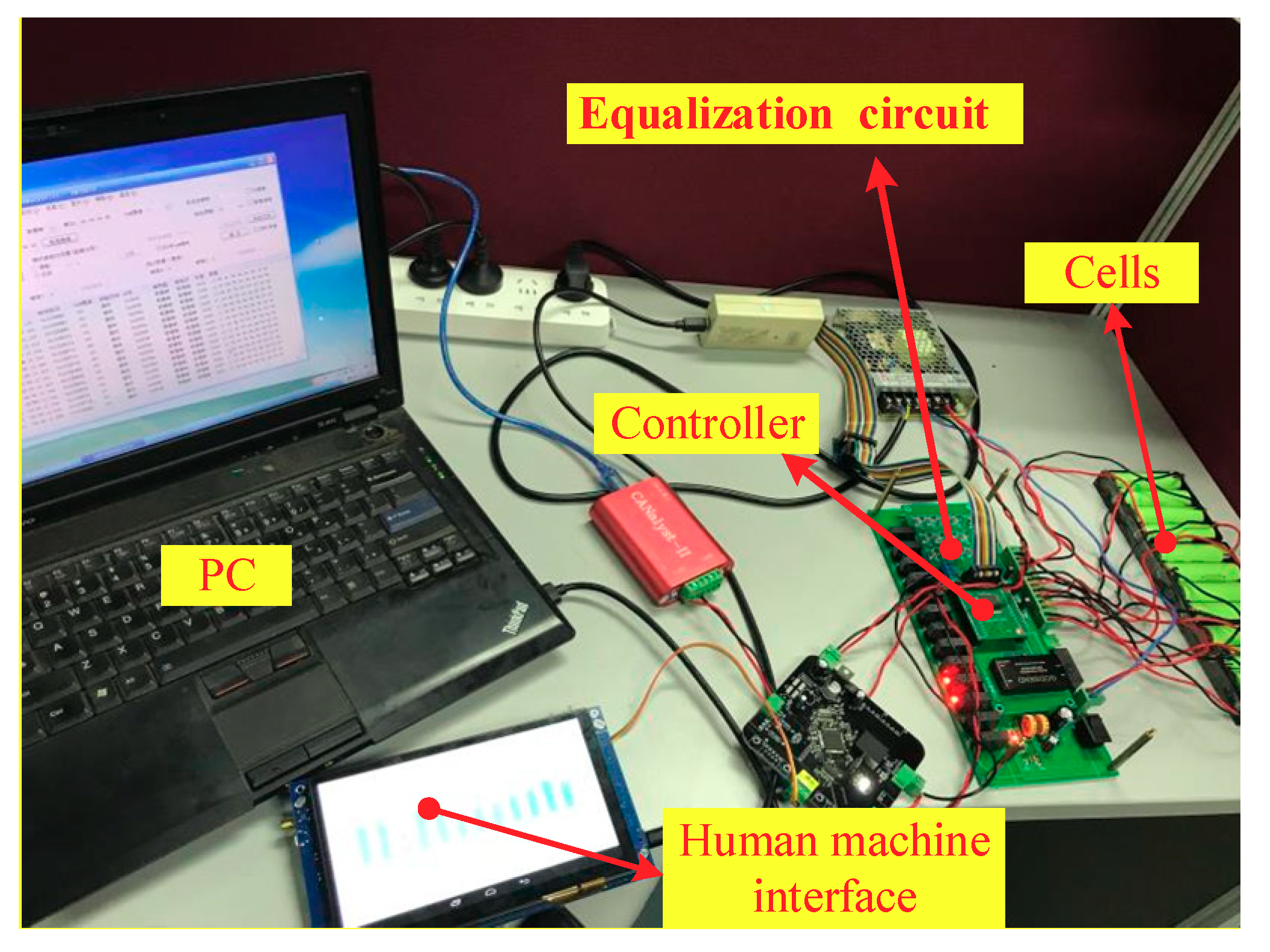
To verify the effectiveness of the proposed equalizer, experimental verification is investigated in this section. The composite equalization system is mainly divided into three parts. The first part is the microcontroller unit (MCU) based on XC164CS (Infineon Technologies, Neubiberg, Germany). The function of this part is to receive the voltage information of all single cells in the battery pack, to drive the corresponding relay switch, and to communicate with the host computer. The second part is the cell voltage acquisition circuit based on LTC6804 (Analog Devices, Norwood, MA, USA). The function of this part is to detect and collect all cell voltage information in the battery pack, and then transmit it to the MCU. The third part is the core equalization circuit, including passive and active equalization. The function of this part is to adjust the voltage level of cells in the battery pack so as to keep the voltage level of cells in good consistency.
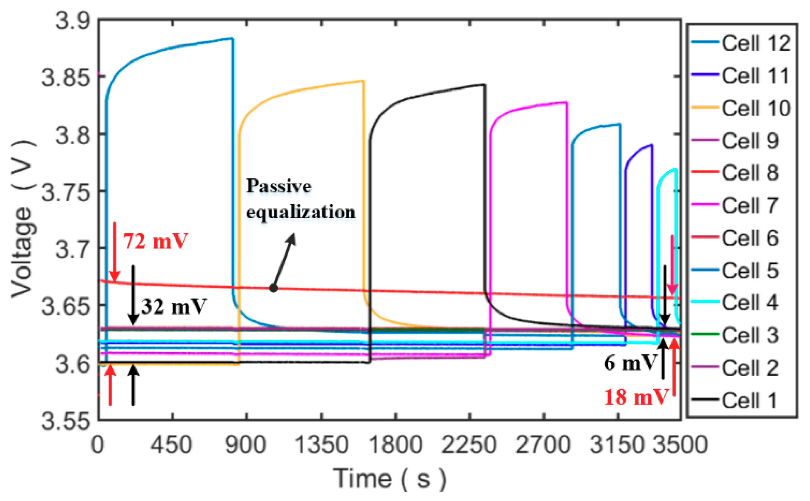
Figure 13 shows the experimental platform. The equalization circuit is the proposed circuit, and the control algorithm is realized in the controller. The data can be read by the human machine interface, and experimental data is recorded by the personal computer (PC). In this experiment, 12 cells are used as test cells for the equalizer, and a cell is used as additional cell. The parameters of the experimental cells are as follows: nominal capacity is 3200 mAh; nominal voltage is 3.6 V, lower and upper cut-off voltage are 2.5 V and 4.2 V, respectively. In the experiment, each cell has different initial SOC, and the SOC of the additional cell is the highest.
Figure 14 shows the experiment results under static condition. It can be seen that the test cells are charged by additional cell. Except Cell 8, the maximum voltage difference between cells is reduced from 32 mV to 6 mV in 3500 s. Moreover, it is obvious that passive equalizer is running (Cell 8) while passive equalizer is turned on, which greatly improves the equalization efficiency. The maximum voltage difference of all cells is reduced from 72 mV to 18 mV.
It is necessary to point out that the speed of passive equalization is slow (Cell 8), which is caused by the smaller voltage difference between cells, which is caused by the smaller equalization current, which is the disadvantage of passive equalization. However, our proposed composite equalization method combines active and passive equalizers to improve equalization efficiency, and our designed active equalizer based on an additional cell has a simpler structure than the traditional active equalizer.
6. Conclusions
In order to improve the consistency of cells in lithium-ion powered battery packs for EVs, a composite equalization method based on an additional cell that combines both active and passive equalizers is proposed. The equalization principle, circuit, control strategy and algorithm are studied through simulation and experiment in many cases. The main conclusions of this study are as follows:
(1) A novel composite equalization method is proposed, and its configuration and circuit are designed. The composite equalization includes passive and active equalization parts. These are mutually independent in structure and are mutually coordinated in function. Passive equalization adopts common energy dissipation equalization by using a bypass resistor. Active equalizer adopts non-dissipative equalization by using an additional cell, which has a simpler structure than the traditional active equalizer.
(2) A composite equalization algorithm containing three equalization modes is proposed. The equalization mode can be switched automatically according to the state of the cells. When the voltage difference between the cell to be equalized and the additional cell is large, active equalization will be used. When the voltage difference between the cell to be equalized and the additional cell is small, passive equalization will be used. The algorithm combines the advantages of the different equalization methods.
(3) The Simscape module in MATLAB/Simulink is used to build a physical model of the composite equalization circuit, and the equalization control strategy and algorithm are modeled in Simulink/Stateflow. The simulation results show that the consistency level of the battery pack improved and the available capacity increased. Moreover, the equalization time of the composite equalization during the static equalization process is obviously shortened compared to single equalization.
(4) Experimental results have shown the proposed equalizer demonstrates a good comprehensive performance of active and passive equalizers.
The proposed method is not sufficient tested and verified in a real battery management system for various cases. Further works include: (a) More intensive verification of the proposed method and algorithm in battery packs for various cases; (b) a more advanced equalization algorithm based on composite equalizer; and (c) equalization control of parallel-connected battery based on our proposed method.
Author Contributions
All authors contributed to the paper. Conceptualization: X.L. and Y.Z.; data curation: C.J. and P.H.; investigation: H.G. and X.L.; methodology: X.L. and L.Z.; project administration: X.L. and Y.Z.; software: C.J.; validation: H.G.; writing (original draft): X.L. and C.J.; writing (review and editing): X.L., C.J., and P.H. All the authors read and approved the final manuscript.
Funding
This research was funded by the National Natural Science Foundation of China (NSFC) under the grant number of 51505290 and 51877138.
Conflicts of Interest
The authors declare no conflict of interest.
References
- Armaroli, N.; Balzani, V. Towards an electricity-powered world. Energy Environ. Sci. 2011, 4, 3193–3222. [Google Scholar] [CrossRef]
- Contestabile, M.; Offer, G.J.; Slade, R.; Jaeger, F.; Thoennes, M. Battery electric vehicles, hydrogen fuel cells and biofuels. Which will be the winner? Energy Environ. Sci. 2011, 4, 3754–3772. [Google Scholar] [CrossRef]
- Lü, X.; Qu, Y.; Wang, Y.; Qin, C.; Liu, G. A comprehensive review on hybrid power system for PEMFC-HEV: Issues and strategies. Energy Convers. Manag. 2018, 171, 1273–1291. [Google Scholar] [CrossRef]
- Lai, X.; Zheng, Y.J.; Sun, T. A comparative study of different equivalent circuit models for estimating state-of-charge of lithium-ion batteries. Electrochim. Acta 2018, 259, 566–577. [Google Scholar] [CrossRef]
- Lai, X.; Zheng, Y.J.; Zhou, L.; Gao, W.K. Electrical behavior of overdischarge-induced internal short circuit in lithium-ion cells. Electrochim. Acta 2018, 278, 245–254. [Google Scholar] [CrossRef]
- Zheng, Y.J.; Ouyang, M.G.; Han, X.B.; Lu, L.G.; Li, J.Q. Investigating the error sources of the online state of charge estimation methods for lithium-ion batteries in electric vehicles. J. Power Sources 2018, 377, 161–188. [Google Scholar] [CrossRef]
- Shareef, H.; Islam, M.M.; Mohamed, A. A review of the stage-of-the-art charging technologies, placement methodologies, and impacts of electric vehicles. Renew. Sustain. Energy Rev. 2016, 64, 403–420. [Google Scholar] [CrossRef]
- Lai, X.; Gao, W.; Zheng, Y.; Ouyang, M.; Li, J.; Han, X.; Zhou, L. A comparative study of global optimization methods for parameter identification of different equivalent circuit models for Li-ion batteries. Electrochim. Acta 2019. [Google Scholar] [CrossRef]
- Xiong, R.; Cao, J.Y.; Yu, Q.Q.; He, H.W.; Sun, F.C. Critical review on the battery state of charge estimation methods for electric vehicles. IEEE Access 2018, 6, 1832–1843. [Google Scholar] [CrossRef]
- Xiong, R.; Cao, J.Y.; Yu, Q.Q. Reinforcement learning-based real-time power management for hybrid energy storage system in the plug-in hybrid electric vehicle. Appl. Energy 2018, 211, 538–548. [Google Scholar] [CrossRef]
- Lai, X.; Qin, C.; Gao, W.; Zheng, Y.; Yi, W. A state of charge estimator based extended kalman filter using an electrochemistry-based equivalent circuit model for lithium-ion batteries. Appl. Sci. 2018, 8, 1592. [Google Scholar] [CrossRef]
- Repp, S.; Harputlu, E.; Gurgen, S.; Castellano, M.; Kremer, N.; Pompe, N.; Worner, J.; Hoffmann, A.; Thomann, R.; Emen, F.M.; et al. Synergetic effects of Fe3+ doped spinel Li4Ti5O12 nanoparticles on reduced graphene oxide for high surface electrode hybrid supercapacitors. Nanoscale 2018, 10, 1877–1884. [Google Scholar] [CrossRef] [PubMed]
- Ouyang, Q.; Chen, J.; Zheng, J.; Hong, Y.G. Soc estimation-based quasi-sliding mode control for cell balancing in lithium-ion battery packs. IEEE Trans. Ind. Electron. 2018, 65, 3427–3436. [Google Scholar] [CrossRef]
- Wei, J.W.; Dong, G.Z.; Chen, Z.H.; Kang, Y. System state estimation and optimal energy control framework for multicell lithium-ion battery system. Appl. Energy 2017, 187, 37–49. [Google Scholar] [CrossRef]
- Lv, J.; Song, W.J.; Lin, S.L.; Chen, M.B.; Feng, Z.P.; Li, Y.L.; Ding, Y.L. Influence of equalization on LiFePO4 battery inconsistency. Int. J. Energy Res. 2017, 41, 1171–1181. [Google Scholar] [CrossRef]
- Gao, W.; Zheng, Y.; Ouyang, M.; Li, J.; Lai, X.; Hu, X. Micro-short circuit diagnosis for series-connected lithium-ion battery packs using mean-difference model. IEEE Trans. Ind. Electron. 2019, 66, 2132–2142. [Google Scholar] [CrossRef]
- Lai, X.; Qiao, D.; Zheng, Y.; Zhou, L. A fuzzy state-of-charge estimation algorithm combining ampere-hour and an extended kalman filter for Li-ion batteries based on multi-model global identification. Appl. Sci. 2018, 8, 2028. [Google Scholar] [CrossRef]
- Zhang, Z.; Kong, X.; Zheng, Y.; Zhou, L.; Lai, X. Real-time diagnosis of micro-short circuit for Li-ion batteries utilizing low-pass filters. Energy 2019, 166, 1013–1024. [Google Scholar] [CrossRef]
- Schmid, A.U.; Eringer, L.; Lambidis, I.; Birke, K.P. Electrochemical balancing of lithium-ion cells by nickel-based cells. J. Power Sources 2017, 367, 49–56. [Google Scholar] [CrossRef]
- Hoque, M.M.; Hannan, M.A.; Mohamed, A.; Ayob, A. Battery charge equalization controller in electric vehicle applications: A review. Renew. Sustain. Energy Rev. 2017, 75, 1363–1385. [Google Scholar] [CrossRef]
- Lu, L.G.; Han, X.B.; Li, J.Q.; Hua, J.F.; Ouyang, M.G. A review on the key issues for lithium-ion battery management in electric vehicles. J. Power Sources 2013, 226, 272–288. [Google Scholar] [CrossRef]
- Baronti, F.; Roncella, R.; Saletti, R. Performance comparison of active balancing techniques for lithium-ion batteries. J. Power Sources 2014, 267, 603–609. [Google Scholar] [CrossRef]
- Dai, H.F.; Zhang, X.L.; Wei, X.Z.; Sun, Z.C.; Wang, J.Y.; Hu, F. Cell-BMS validation with a hardware-in-the-loop simulation of lithium-ion battery cells for electric vehicles. Int. J. Electr. Power 2013, 52, 174–184. [Google Scholar] [CrossRef]
- Uno, M.; Tanaka, K. Single-switch cell voltage equalizer using multistacked buck-boost converters operating in discontinuous conduction mode for series-connected energy storage cells. IEEE Trans. Veh. Technol. 2011, 60, 3635–3645. [Google Scholar] [CrossRef]
- Zhang, X.; Wang, Y.J.; Liu, C.; Chen, Z.H. A novel approach of remaining discharge energy prediction for large format lithium-ion battery pack. J. Power Sources 2017, 343, 216–225. [Google Scholar] [CrossRef]
- Lee, S.W.; Lee, K.M.; Choi, Y.G.; Kang, B. Modularized design of active charge equalizer for Li-ion battery pack. IEEE Trans. Ind. Electron. 2018, 65, 8697–8706. [Google Scholar] [CrossRef]
- Wang, Y.J.; Zhang, C.B.; Chen, Z.H.; Xie, J.; Zhang, X. A novel active equalization method for lithium-ion batteries in electric vehicles. Appl. Energy 2015, 145, 36–42. [Google Scholar] [CrossRef]
- Bouchhima, N.; Schnierle, M.; Schulte, S.; Birke, K.P. Active model-based balancing strategy for self-reconfigurable batteries. J. Power Sources 2016, 322, 129–137. [Google Scholar] [CrossRef]
- Gallardo-Lozano, J.; Romero-Cadaval, E.; Milanes-Montero, M.I.; Guerrero-Martinez, M.A. Battery equalization active methods. J. Power Sources 2014, 246, 934–949. [Google Scholar] [CrossRef]
- Gallardo-Lozano, J.; Romero-Cadaval, E.; Milanes-Montero, M.I.; Guerrero-Martinez, M.A. A novel active battery equalization control with on-line unhealthy cell detection and cell change decision. J. Power Sources 2015, 299, 356–370. [Google Scholar] [CrossRef]
- Evzelman, M.; Rehman, M.M.U.; Hathaway, K.; Zane, R.; Costinett, D.; Maksimovic, D. Active balancing system for electric vehicles with incorporated low-voltage bus. IEEE Trans. Power Electr. 2016, 31, 7887–7895. [Google Scholar] [CrossRef]
- Hsieh, Y.H.; Liang, T.J.; Chen, S.M.; Horng, W.Y.; Chung, Y.Y. A novel high-efficiency compact-size low-cost balancing method for series-connected battery applications. IEEE Trans. Power Electr. 2013, 28, 5927–5939. [Google Scholar] [CrossRef]
- Lai, X.; Yi, W.; Zheng, Y.; Zhou, L. An All-Region State-of-Charge Estimator Based on Global Particle Swarm Optimization and Improved Extended Kalman Filter for Lithium-Ion Batteries. Electronics 2018, 7, 321. [Google Scholar] [CrossRef]
- Zhou, L.; Zheng, Y.J.; Ouyang, M.G.; Lu, L.G. A study on parameter variation effects on battery packs for electric vehicles. J. Power Sources 2017, 364, 242–252. [Google Scholar] [CrossRef]
Figure 1.
Configuration and circuit of composite equalization. (a) Configuration; (b) passive equalization circuit; and (c) active equalization circuit.
Figure 1.
Configuration and circuit of composite equalization. (a) Configuration; (b) passive equalization circuit; and (c) active equalization circuit.


Figure 2.
Principle of composite equalization. (a) First active equalization mode; (b) second active equalization mode; and (c) passive equalization mode.
Figure 2.
Principle of composite equalization. (a) First active equalization mode; (b) second active equalization mode; and (c) passive equalization mode.

Figure 3.
Flow chart of composite equalization control strategy. (a) Selection of composite equalization mode; (b) passive equalization mode; and (c) active equalization mode.
Figure 3.
Flow chart of composite equalization control strategy. (a) Selection of composite equalization mode; (b) passive equalization mode; and (c) active equalization mode.


Figure 4.
Simulation model of composite equalization. (a) Circuit configuration using Simscape in MATLAB; (b) passive equalization mode; and (c) active equalization mode.
Figure 4.
Simulation model of composite equalization. (a) Circuit configuration using Simscape in MATLAB; (b) passive equalization mode; and (c) active equalization mode.

Figure 5.
Simulation results of charging equalization. (a) Case A: no equalization; (b) Case B: SOC (State of Charge) of C0 = 2%; (c) Case C: SOC of C0 = 50%; and (d) Case D: SOC of C0 = 98%.
Figure 5.
Simulation results of charging equalization. (a) Case A: no equalization; (b) Case B: SOC (State of Charge) of C0 = 2%; (c) Case C: SOC of C0 = 50%; and (d) Case D: SOC of C0 = 98%.


Figure 6.
Battery pack capacity after charging.

Figure 7.
Simulation results of discharging equalization. (a) Case E: no equalization; (b) Case F: SOC of C0 = 2%; (c) Case G: SOC of C0 = 50%; and (d) Case H: SOC of C0 = 98%.
Figure 7.
Simulation results of discharging equalization. (a) Case E: no equalization; (b) Case F: SOC of C0 = 2%; (c) Case G: SOC of C0 = 50%; and (d) Case H: SOC of C0 = 98%.

Figure 8.
Battery pack capacity after discharging.

Figure 9.
Simulation results of static equalization. (a) Case J: SOC of C0 = 36%; (b) Case K: SOC of C0 = 52%; and (c) Case L: SOC of C0 = 68%.
Figure 9.
Simulation results of static equalization. (a) Case J: SOC of C0 = 36%; (b) Case K: SOC of C0 = 52%; and (c) Case L: SOC of C0 = 68%.

Figure 10.
Battery pack capacity (static).

Figure 11.
Simulation results of single equalization. (a) Passive equalization; (b) Active equalization (SOC of C0 = 36%); (c) active equalization (SOC of C0 = 52%); and (d) active equalization (SOC of C0 = 68%).
Figure 11.
Simulation results of single equalization. (a) Passive equalization; (b) Active equalization (SOC of C0 = 36%); (c) active equalization (SOC of C0 = 52%); and (d) active equalization (SOC of C0 = 68%).

Figure 12.
Comparison of simulation time for three different equalization methods.

Figure 13.
Experimental platform of the proposed equalizer.

Figure 14.
Experimental result under static condition.


Table 1.
Charging time comparison.
| Case | Charging Time (s) |
|---|---|
| A | 7602 |
| B | 8022 |
| C | 8044 |
| D | 7783 |
Table 2.
Voltage range and SOC (State of Charge) extremum after charging.
| Case | Voltage Range (mV) | Maximum of SOC (%) | Minimum of SOC (%) |
|---|---|---|---|
| A | 43.20 | 78.9709 | 69.4039 |
| B | 27.50 | 78.9935 | 73.2911 |
| C | 27.70 | 79.1225 | 76.7093 |
| D | 14.20 | 80.1918 | 76.2118 |
Table 3.
Discharging time comparison.
| Case | Discharging Time (s) |
|---|---|
| E | 9948 |
| F | 10,189 |
| G | 10,610 |
| H | 10,841 |
Table 4.
Voltage range and SOC extremum after discharging.
| Case | Voltage Range (mV) | Maximum of SOC (%) | Minimum of SOC (%) |
|---|---|---|---|
| E | 789.10 | 6.3843 | 0.0063 |
| F | 95.10 | 0.6933 | 0.0019 |
| G | 40.30 | 0.0477 | 0.0008 |
| H | 21.80 | 0.0482 | 0.0046 |
Table 5.
Equalization time comparison.
| Case | Equalization Time (s) |
|---|---|
| I 1 | None |
| J | 86,400 |
| K | 86,800 |
| L | 48,300 |
1 No equalization.
Table 6.
Voltage range and SOC extremum after static equalization.
| Case | Voltage Range (mV) | Maximum of SOC (%) | Minimum of SOC (%) |
|---|---|---|---|
| I 1 | 36.60 | 55.3540 | 42.5980 |
| J | 5.10 | 44.0755 | 42.5843 |
| K | 5.00 | 47.7993 | 45.7882 |
| L | 5.10 | 52.8665 | 50.5495 |
1 No equalization.
© 2018 by the authors. Licensee MDPI, Basel, Switzerland. This article is an open access article distributed under the terms and conditions of the Creative Commons Attribution (CC BY) license (http://creativecommons.org/licenses/by/4.0/).
Share and Cite
MDPI and ACS Style
Lai, X.; Jiang, C.; Zheng, Y.; Gao, H.; Huang, P.; Zhou, L. A Novel Composite Equalizer Based on an Additional Cell for Series-Connected Lithium-Ion Cells. Electronics 2018, 7, 366. https://doi.org/10.3390/electronics7120366
AMA Style
Lai X, Jiang C, Zheng Y, Gao H, Huang P, Zhou L. A Novel Composite Equalizer Based on an Additional Cell for Series-Connected Lithium-Ion Cells. Electronics. 2018; 7(12):366. https://doi.org/10.3390/electronics7120366
Chicago/Turabian StyleLai, Xin, Chun Jiang, Yuejiu Zheng, Han Gao, Peng Huang, and Long Zhou. 2018. "A Novel Composite Equalizer Based on an Additional Cell for Series-Connected Lithium-Ion Cells" Electronics 7, no. 12: 366. https://doi.org/10.3390/electronics7120366
Note that from the first issue of 2016, this journal uses article numbers instead of page numbers. See further details here.