A Cross-Layer Biometric Recognition System for Mobile IoT Devices


Department of Electrical and Computer Engineering, University of Central Florida, Orlando, FL 32816, USA
*
Author to whom correspondence should be addressed.
Electronics 2018, 7(2), 26; https://doi.org/10.3390/electronics7020026
Submission received: 29 January 2018
/
Revised: 13 February 2018
/
Accepted: 21 February 2018
/
Published: 24 February 2018
Abstract
:A biometric recognition system is one of the leading candidates for the current and the next generation of smart visual systems. The visual system is the engine of the surveillance cameras that have great importance for intelligence and security purposes. These surveillance devices can be a target of adversaries for accomplishing various malicious scenarios such as disabling the camera in critical times or the lack of recognition of a criminal. In this work, we propose a cross-layer biometric recognition system that has small computational complexity and is suitable for mobile Internet of Things (IoT) devices. Furthermore, due to the involvement of both hardware and software in realizing this system in a decussate and chaining structure, it is easier to locate and provide alternative paths for the system flow in the case of an attack. For security analysis of this system, one of the elements of this system named the advanced encryption standard (AES) is infected by four different Hardware Trojansthat target different parts of this module. The purpose of these Trojans is to sabotage the biometric data that are under process by the biometric recognition system. All of the software and the hardware modules of this system are implemented using MATLAB and Verilog HDL, respectively. According to the performance evaluation results, the system shows an acceptable performance in recognizing healthy biometric data. It is able to detect the infected data, as well. With respect to its hardware results, the system may not contribute significantly to the hardware design parameters of a surveillance camera considering all the hardware elements within the device.
1. Introduction
The current generation of the Internet network enables user participation, collaboration and interaction through two-way communication and improves the intelligence of machines and search engines by translating the network information from a high-level to a low-level standardized format. Advancement in other technologies, such as wireless communication and electronic systems’ design merged with this network, leads to a framework that provides the participation and interaction of a massive number of electronic devices over the world-wide network. This framework is called the Internet of Things (IoT) in which everything (i.e., every object) becomes smart by attaching/embedding an electronic module to/inside it and has access to the world-wide network, using its unique features and address, at any time and any place for interaction with other things, as well as network services [1]. The electronic module of everything makes the object capable of identifying, sensing, localizing, connecting and communicating, processing information, predicting, making decisions and invoking action. Furthermore, everything can be controlled and managed remotely through the Internet servers. This enormous exchange of information between everything (which means among devices and servers) helps influence every action in this world in real time. Consequently, every smart thing in this promising smart world (also known as the IoT world) can be positioned anywhere, such as military systems, transportation systems and visual systems.
The smart visual system (or the IoT visual system) has attracted the research community in spite of the increased concern and worries of privacy advocates. The state of the art technologies, namely biometrics, crowd monitoring and automated human activity recognition, can assist the system in the handling of the video feeds from a large number of surveillance cameras. Due to the vital demand to provide a safer environment along with the increased anxiety about combating crimes and terror attacks, the number of surveillance systems, such as automated closed-circuit television (CCTV), installed in the metropolitan areas in many countries has increased tremendously. The biometric technology has been leveraged in many of these systems to ease the management and monitoring of the operations of the cameras, especially for its capability to screen a large number of video feeds across different places in a real-time, remote, non-cooperative and non-invasive way.
The importance of biometric technology for surveillance purposes is extremely high [2,3]. The military forces of the United States, besides the country intelligence agencies, have utilized this technology for their intelligence, surveillance, target acquisition and reconnaissance (ISTR) activities. The incident of the September 11th attacks (coordinated by the al-Qaeda Islamic terrorist group) accelerated and extended the usage of this technology in different areas of national security such as surveillance applications in counter-terrorism and counter-piracy operations, identity management systems, crime detection, international border crossing, time and attendance management systems, government and law enforcement, DNA profiling, passport-free automated border crossings, collecting security intelligence information and the determination of friend or enemy in military installation.
In this regard, we study an application of biometric technology named the biometric recognition system here. The contributions of this paper can be stated as: (1) proposing a cross-layer biometric recognition system suitable for mobile IoT devices; and (2) proposing four Hardware Trojans (HTs) for the advanced encryption standard (AES) hardware unit positioned within this system. Section 2 presents the background on the area of the biometric recognition system. The security challenges for a hardware-software (cross-layer) biometric recognition system are discussed in Section 3. The system architecture is introduced in Section 4. The description of the designed Hardware Trojans is provided in Section 5. The results, analysis and discussion are presented in Section 6. The conclusion is given in Section 7.
2. The Background on the Biometric Recognition System
The process of acquiring, measuring and analyzing a range of human physiological characteristics is called biometrics. The measurement is defined as deriving descriptive or quantitative measurements from the characteristics for usage in a more accurate analysis. The appearance, behavior and cognition state of a human being can all be included in the scope of characteristics. The major properties of a biometric characteristic are uniqueness (which means having exclusive traits), permanence (which means being consistent across time) and universality (which means it is obtainable from all the individuals in the population). The primary advantages of biometric identifiers compared to their traditional counterparts (i.e., user-name and password) are their precise identification, highest level of security, mobility, difficulty in forging, being unforgettable, not being transferable and user friendliness.
In this context, a biometric system is defined as a pattern recognition machine that acquires physiological characteristic data from an individual person, extracts a notable feature set from the data, compares the feature set of input data (from an unknown source) against the feature set of the reference data (from a trustworthy source) stored in the database and provides the comparison results. The system can have two functionality modes depending on its application: identification and verification/authentication [4]. In identification mode, it identifies an individual by searching the feature sets of all the individuals by conducting a one-to-many comparison, while the comparison is one-to-one in verification mode. Furthermore, the system should be initialized before being prepared to deliver its functionalities. The initialization phase is called enrollment. In this phase, the authentic biometric characteristics are captured and processed. Next, their features are extracted and stored on the database.
Commonly, this machine consists of five main modules to deliver this functionality: (a) the sensor module, which acquires the raw biometric data of an individual by scanning and reading; every type of biometric characteristic or data needs to be measured by a certain type of sensor; (b) the quality assessment and enhancement module, which assesses and enhances the data quality by the respective algorithms; (c) the feature extraction module, which extracts a set of discriminatory features from the data to represent the underlying trait and structure; (d) the matching and decision making module, which compares the input feature set against the reference feature set and calculates a matching score for identity validation; the higher matching score demonstrates more accordance between the two feature sets; the assessment afterward of all the matching scores renders the recognition of all the individuals; (e) the system database module, which is the storage for all the reference feature sets (obtained during the enrollment process). If there is a storage limitation, a data compression and data decompression can be positioned in the biometric system architecture. It should be mentioned that the biometric systems usually identify individuals based on the nearest matches rather than the exact matches due to the variations among different instances of a biometric characteristic of an individual.
An individual characteristic should have seven factors to be a candidate for a biometric system: (1) universality, which means it is possessed by every individual; (2) uniqueness, which means a sufficient difference exists across individuals comprising the population; (3) permanence, which means it should not change significantly over a period of time; (4) measurable, which means it should be easy to digitize and compatible with the computing process; (5) performance, which means it should comply with the recognition accuracy requirements; (6) acceptability, which means all the individuals in the population are willing to present this characteristic; and (7) circumvention, which means the system should be immune to fake characteristics.
Examples of biometric characteristics that have been successfully used in security applications include face, fingerprint, palm print, iris, palm/finger vasculature structure and voice [5]. Among these characteristics, fingerprint and iris have captured remarkable attention for security checking purposes. Fingerprint has been used in criminal investigation for a long period of time and is known to provide good accuracy, good execution time and good security. A fingerprint is the pattern of friction ridges and valleys on the surface of a fingertip, the formation of which is determined during the first seven months of fetal development. A common way to compare two fingerprints is locating all their unique minutiae and ridge points and running a matching algorithm on the extracted feature sets to calculate the similarity score.
The initial deployment of iris recognition was at airports to replace passport presentation (or any other means for identity assessment) and is reputed for its excellent accuracy, fair execution time and excellent security. The iris is the annular region of the eye bounded by the pupil and the sclera (which is the white part of the eye) on either side. The visual texture of the iris is formed during fetal development and is stabilized during the first two years of life. It contains very distinctive and useful information for personal recognition. The texture features of two irises can be input to a matching algorithm in order to compare them.
3. The Security Challenges for a Cross-Layer Biometric Recognition System
An important challenge faced by a biometric system relates to the possibility of identity theft. What if a malicious person gets access to the biometric characteristic of an individual and performs an active or a passive attack (such as damaging the information or stealing the information)? Considering the fact that biometric data cannot be changed and canceled (easily), the security issue becomes worse. The intrusion can happen by any software or hardware means in different scenarios. In one scenario, all the enrolled users in a network can identify each other through their fingerprint and/or iris to be taken by their own cellphones. In another scenario, a small portable surveillance system transmits the biometric information to the operator’s cellphone. One solution for this security issue is encrypting the biometric data at the hardware- or the software-level before being sent to the involved units for the identification/authentication functionality.
About ten years ago, the hardware implementation of security algorithms could be considered as a more trustworthy element for security provision. Nowadays, any hardware or integrated circuit (IC) chip can be a target of various attacks. ICs usually adopt the system-on-chip (SoC) technique as their design principle for acceleration of their design-to-usage process. According to this technique, the IC designer (or SoC integrator) builds and implements a specified main function and its circuit by forming the essential interconnections between the delivered analog and digital intellectual property (IP) cores (or sub-circuits) by third parties (external sources). The chip designs by unknown external sources in the diverse environment of the semiconductor supply chain may not be trustworthy. It is probable for a design to render an alternative function due to an applied malicious change to its circuit, which is known as a Hardware Trojan (HT). A Trojan should be activated by a rare event (to be sneaky), and it can be designed and inserted during design or fabrication processes by untrusted people, design tools or modules. In other words, it manipulates the functionality for a certain data pattern and/or after a certain number of clock cycles. Hardware Trojans can create catastrophic and life-threatening situations in surveillance systems such as corrupting the biometric data to dismantle an authorized access or achieving an illegal access through misidentification/misauthentication.
4. The Cross-Layer Biometric Recognition System
In this section, a cross-layer biometric recognition system with small computational complexity suitable for mobile IoT devices is presented. In a cross-layer (hardware-software) system, the entire design problem is partitioned into manageable areas of expertise, which means small, separate and interchangeable components. Having well-defined, strict and logical interfaces within the system allows each of the leveraged layers in the system to operate independently. They are designed by different sets of experts, such as control theorists, compiler designers, software engineers, operating system designers, embedded system designers, computer architects, circuit designers and semiconductor experts. All the layers in this system architecture are employed to store information and coordinate their actions in order to jointly improve the system performance. This helps achieve phenomenal advancements in the design and development of biometric recognition systems.
The software components run on the computing cores, and the hardware components are used to accelerate some parts of the application, as well as providing interfaces to the environment. This helps extract benefits from further scaled transistor and memory technologies (such as tunnel field effect transistors or magnetic tunnel junctions) within these systems. The system modularity makes the optimization, management and maintenance processes easier. With these features, a higher level of robustness is provided in front of unpredictable events, such as node failure, loss of connectivity, security attack, reduction of channel capacity or anomalies in communications. Furthermore, the quality of the system service can be tuned according to different applications. In this heterogeneous architecture, the software elements can be changed without affecting the hardware elements, and the hardware elements can simply reuse the functionality provided by the software elements. However, the system has its disadvantages, as well: (a) suboptimal, which means layering brings redundancy to the system (i.e., multiple elements performing the same function); (b) information hiding, which means each layer may not easily access the processing information within another layer (while it can have security privileges); and (c) performance degradation if there are strict constraints on the system quality of service.
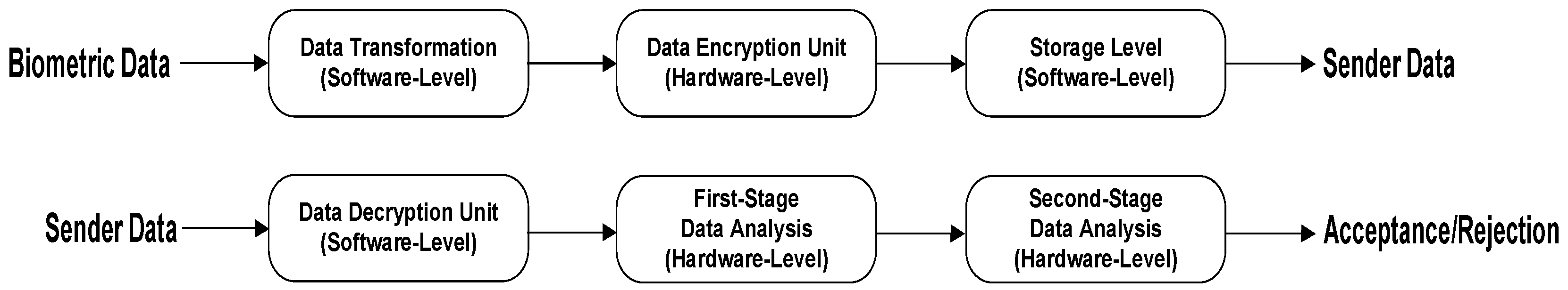
Our system architecture is shown in Figure 1. The system needs to go to an initialization or user enrollment phase in the beginning. The architecture has two sides: the Sender and the Receiver. At the sender side, an individual takes his/her biometric data (fingerprint and/or iris here) using a cellphone or any other type of mobile device. After data acquisition, it is transformed into a number of 128-bit in-sequence plaintext blocks by a built-in software module within the device. The transformed data blocks stay in a queue dedicated to plaintext. Next, the data blocks based on their priority (based on their order in the sequence) are sent to a 128-bit AES hardware module for encryption. Once a data block is encrypted, it is sent to stay in a queue dedicated to ciphertext.
At the receiverside, the ciphertexts are captured one by one and are stored in a queue. Next, they are sent to a software-level AES decryption module. After decryption, the biometric data are reconstructed and sent to the first-level data analysis hardware unit. In this unit, twelve basic statistical measures from the biometric data are compared against their reference values, which are stored in either registers or memory. The statistical measures are: (1) the number of maximum values; (2) the average value; (3) the median value; (4) the number of minimum values; (5) the mode (or the smallest frequent value); (6) the standard deviation; (7) the number of values that is greater than a high threshold value; (8) the number of values that is less than a low threshold value; (9) the kurtosis; (10) the skewness; (11) the Manhattan norm; and (12) the Euclidean norm. The high threshold value is equal to the mean of the biometric data plus the standard deviation of the data multiplied by three. The low threshold value is equal to the mean of the biometric data. The biometric data are accepted to be sent to the next stage of the recognition system if nine out of twelve statistical measures have their values within a selected tolerance boundary. If the data do not comply with this condition, they are rejected, and the process is stopped.
At the next stage, the biometric data are filtered in order to eliminate noise or any malicious effect introduced into the data. Performing a comparison on the filtered data in this step helps to detect fake biometric data, as well. Average filtering with a window size of three is used for this purpose. Then, the filtered data are sent to the second-level data analysis hardware unit. In this unit, four distance measures are leveraged to compare the filtered biometric data block against the reference biometric data. The distance measures are: (a) the average of the Euclidean distance; (b) the average of the city block (Manhattan) distance; (c) the average of the Hamming distance; and (d) the average of the Chebyshev distance. Next, the calculated values for the distance measures of the test biometric data are compared against their reference values (i.e., the values for four distance measures between the filtered reference biometric data block against the reference biometric data). An acceptance happens when three out of four of the distance measures are within the selected tolerance boundary. This process continues for all of the entering data to the receiver side. The process flow of this system is shown in Algorithm 1.
| Algorithm 1 The flow of the cross-layer biometric recognition system. |
|
5. Attacks on the Cross-Layer Biometric Recognition System
In this section, four new Hardware Trojans for the AES hardware module are presented as attacks on the proposed biometric recognition system. The existing works related to the security vulnerabilities of the AES cryptographic hardware are [6,7]. These Trojans target the hardware functionality in order to harm the biometric data. Our scenario for these Trojans is that they are not detected during the testing and verification phase since the “Mate Trigger” for the “Main Trigger” of each Hardware Trojan is generated by other parts of the SoC during the “chip run-time operation”. In other words, the mate trigger and the main trigger for each Trojan go to an AND function before being applied to the Trojan payload part. Meanwhile, the main trigger mechanism of each Trojan circuit is designed based on the principle of making its activation “random” and “sneaky”.
Without considering this scenario, the Trojans are not sneaky enough in terms of activation time, and the changes caused in the hardware functionality are considered as limitations. By taking the scenario into account, the function-targeting Hardware Trojans may not be detected during the testing phase since there is no knowledge about the application that is going to be run on the chip. Therefore, there is less controllability and observability for each Trojan circuitry, and they behave more covertly. Furthermore, we can consider a scenario for Hardware Trojan implementation according to which the idle cells (or the time-based unused cells) of the SoC chip are detected and employed adaptively in order to construct the Trojan functionality. In addition, hardware obfuscation may reduce the possibility of detecting the Trojans through physical inspection. The area overheads for the Trojans are calculated, considering the insertion of “extra” cells to implement the Trojans. Without the discussed scenario, these Trojans have limitations in terms of the added circuitry. Meanwhile, only the main trigger is considered for activation of the Trojans here.
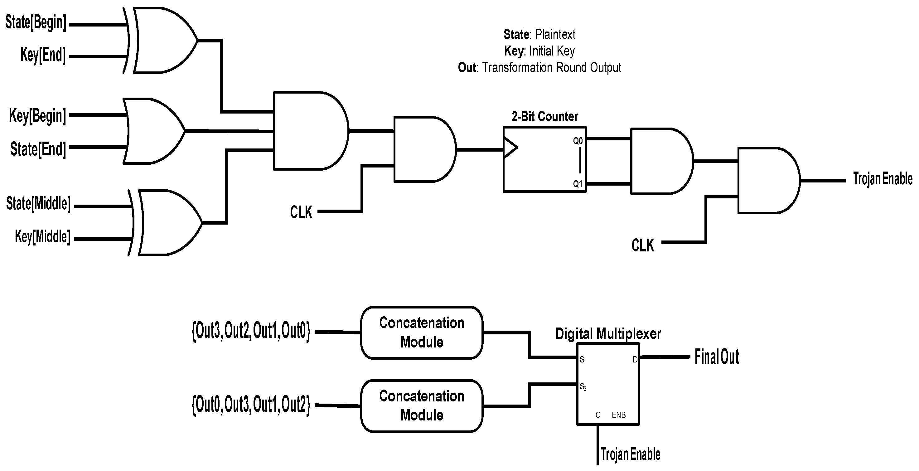
Our first attack targets the output of the intermediate transformation round within the AES algorithm. The trigger circuit and the payload circuit of this attack are shown in the top and the bottom parts of Figure 2, respectively. According to the trigger circuit, the first, the last and the middle data points of the plaintext and the initial key are chosen. The first data point of the plaintext and the last data point of the key go to an exclusive-OR (XOR) gate; the first data point of the key and the last data point of the plaintext enter an OR gate; and middle data points of the plaintext and the key enter an XOR gate. The resulting three signals go to an AND gate. The gate output signal and the clock signal are sent to another AND gate. The obtained signal from this process triggers a two-bit counter. Whenever the counter reaches its saturation state and also the clock signal is in its active state, the enable signal of the HT becomes active. The output of the intermediate transformation round is built by four 32-bit data elements that are constructed by performing the XOR operation on the round sub-keys and the outputs of the lookup table. If the HT becomes active, then the order of these data elements is changed before being sent to the output port of the intermediate transformation round.
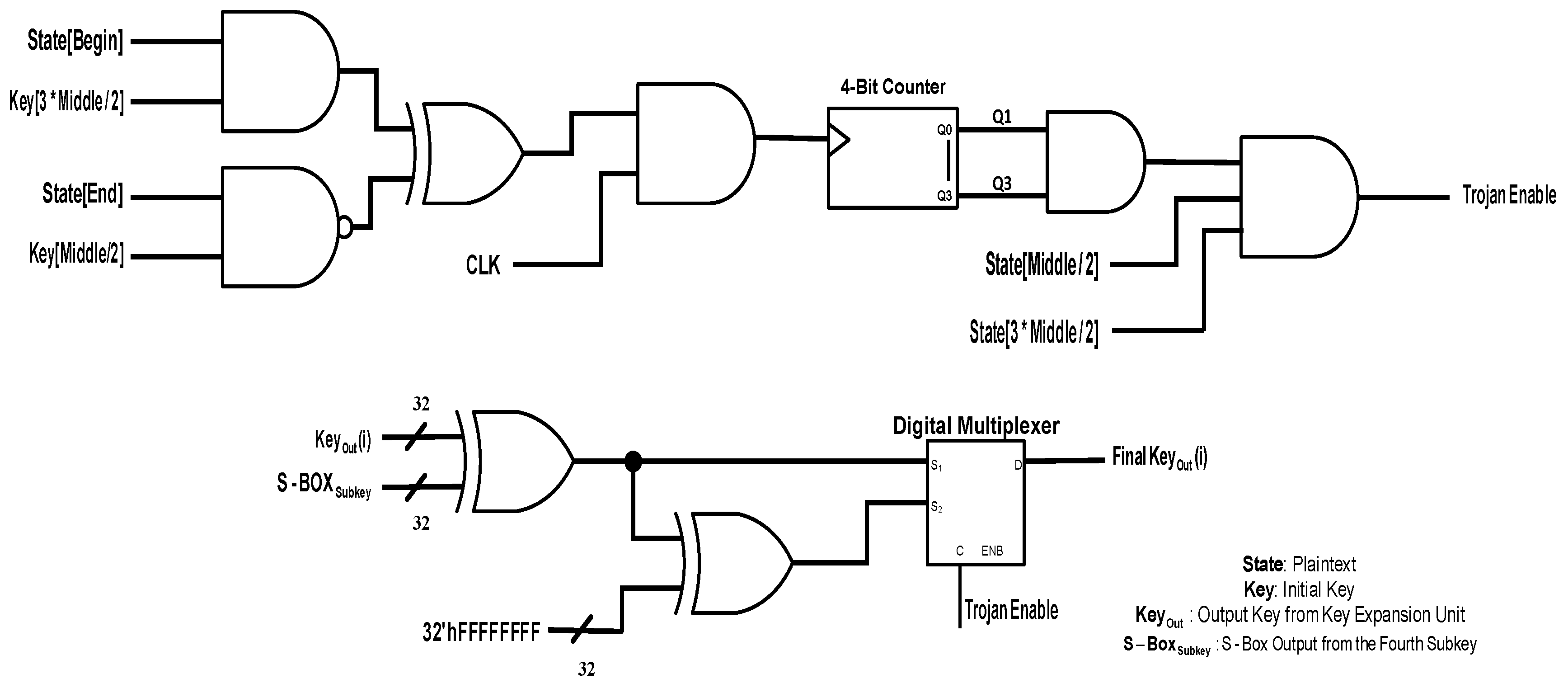
The second attack targets the data elements that make the output key generated by the key expansion unit. The trigger and the payload circuits of this attack are shown in Figure 3. For the trigger circuit, the first and the last data points of the plaintext are selected. Furthermore, the middle data points in the first and the second half of the key are chosen. The first data point of the plaintext and the middle data point of the first and the second halves of the key are sent to an AND gate, and the other data points are dispatched to an NAND gate. The resulting signals go to an XOR gate. Next, the generated signal and the clock signal enter an AND gate to make the trigger signal for the four-bit counter. The first and the last bits of the counter are sent to an AND gate, and the yield signal goes to an AND function along with the middle data point of the first and the second halves of the plaintext. The outcome signal is the enable signal for the Hardware Trojan. In the normal operation of the key expansion unit, each data element is made by performing the XOR operation on its corresponding sub-key and the substitution-box (S-Box) output when its input is the fourth sub-key. When the HT becomes active, all the bits of the data element are XORed with the logical value of one.
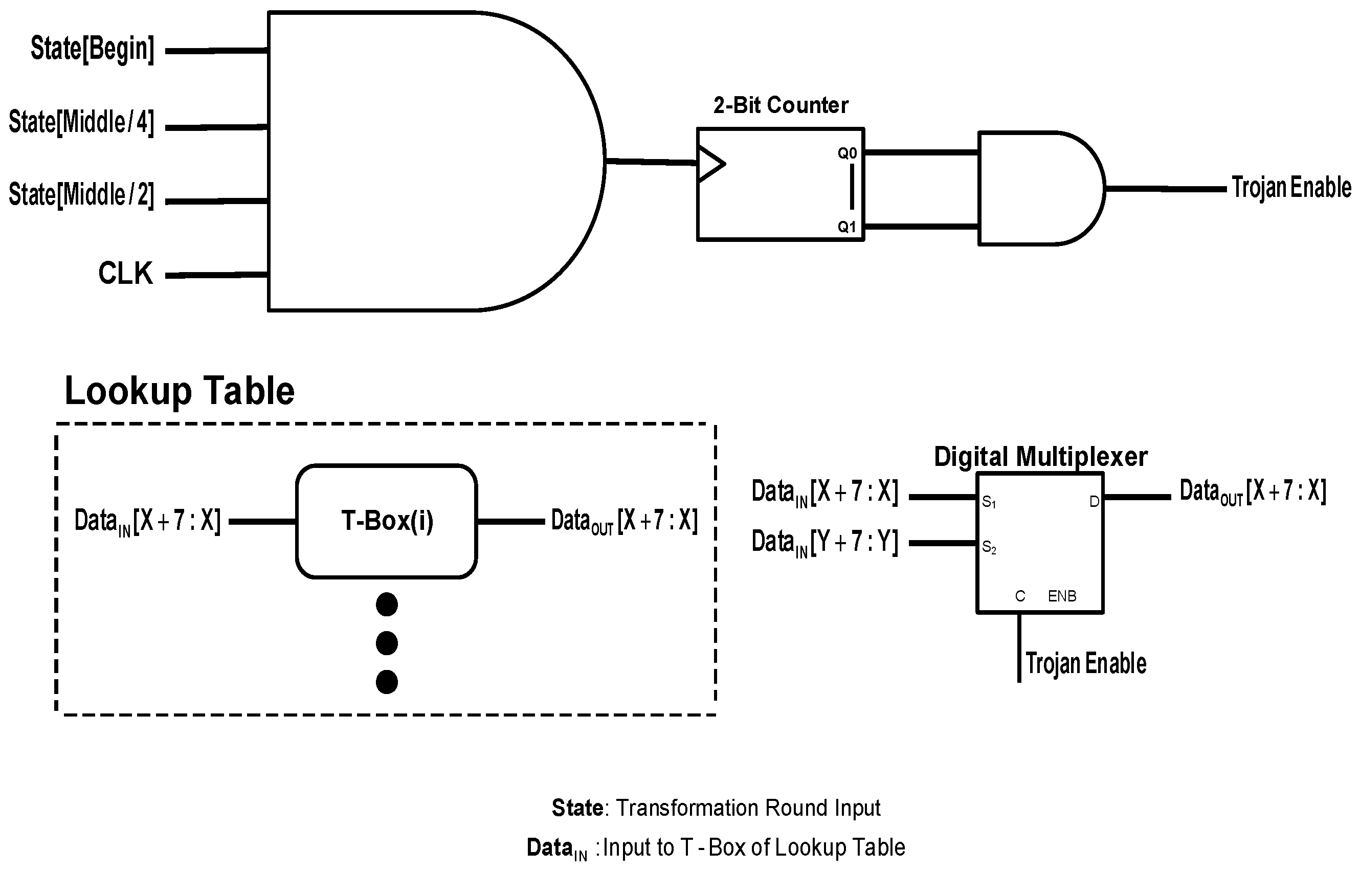
The third attack targets the output of the table boxes (T-Boxes) within the lookup table. The structure of the trigger circuit and the payload circuit for this attack are shown in Figure 4. For the trigger circuit, the first data point along with the one-fourth and the middle data points of the first half of the input data to the intermediate transformation round along with the clock signal are sent to an AND gate. The gate output signal triggers a two-bit counter. When the counter reaches its saturation state, the Hardware Trojan becomes active. Once it becomes activated, a replacement happens between different portions of the input data to a T-Box. Considering four portions for the input data, the first portion is placed for the last portion, the last portion for the second portion and the second portion for the first portion. The third portion stays the same.
The fourth attack targets the S-Box output for malicious manipulation. The structure of this attack is shown in Figure 5. For the trigger circuit, two pairs of data, each consisting of three bits, are selected. In each pair, a data point with a certain index is chosen (either zero or one), and the index of the second data point is the first data point plus three, and the index of the third data point is the second data point plus three. The pair of data with the starting index of zero goes to an XOR gate, and the other one goes to an AND gate. The output signals from these two gates are transmitted to an XOR gate. The resulting signal is the enable signal for the HT. When the Trojan becomes active, the first and the last bits of the S-Box are replaced.
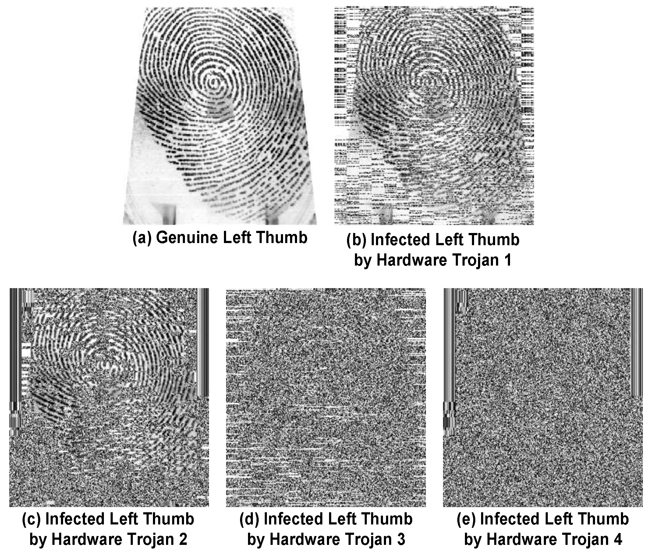
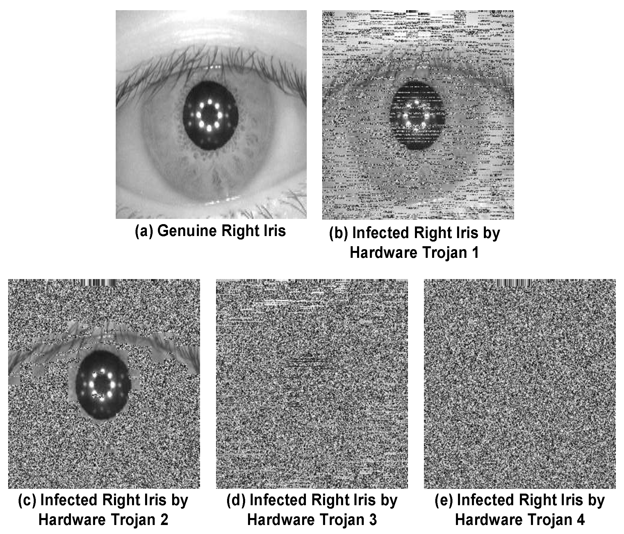
Figure 6, Figure 7, Figure 8 and Figure 9 show the effects of these Hardware Trojans on two biometrics of fingerprint and iris. The used biometric data in this experiment are from the Institute of Automation, Chinese Academy of Sciences (CASIA) -FingerprintV5 and the CASIA-IrisV4 datasets [8,9]. Among all the fingerprints in the dataset, the thumb is selected. The indices of these data instances in the datasets are: 139 for the left thumb, 100 for the right thumb, 94 for the left iris and 50 for the right iris. The utilized AES hardware module in this experiment is from [10]. All the software and the hardware implementation of the modules are done using MATLAB and Verilog HDL, respectively. It is assumed that these are the decrypted data at the receiver side. As can be seen from the figures, the first attack makes the biometric data blurry at the receiver side. However, the structure of the fingerprint or the iris can still be observed. The second attack is more destructive than the first attack, and only a small portion of the biometric data can be seen. Both the third and the fourth attacks fully annihilate the data, but it is believed that the third attack still leaves a minor pattern in the image intact (shown in Part (b) of Figure 7).
6. Results and Discussion
In this section, the results of the performance evaluation and the hardware synthesis of the proposed biometric recognition system are presented. All the biometric images are resized to pixels, and the software and the hardware modules of the system are implemented accordingly. Fifty subjects are selected from each of the CASIA-FingerprintV5 and the CASIA-IrisV4 datasets for performance evaluation. The chosen subjects for the fingerprint dataset are 50–99, and the ones for the iris dataset are 1 and 100–149 (except 147). The performance evaluation of the biometric recognition system is done using four statistical metrics: (1) the true positive rate, which is the rate of correctly-accepted data samples; (2) true negative rate, which is the rate of correctly-rejected data samples; (3) false positive rate, which is the rate of wrongly-rejected data samples; and (4) false negative rate, which is the rate of wrongly-accepted data samples. Furthermore, the evaluation of each dataset is done for seven different threshold values. For each biometric, the assessment is done through comparing the first image of the biometric data of each person against the second to the fifth images of the biometric data of all the registered people. In order to evaluate the system performance for the malicious incidents as well, two infection cases are developed. For each infection case, ten images from ten people from the set of each biometric data type (which means the left/right side of the fingerprint/iris) are infected by the designed Hardware Trojans. For the first infection case, the third image of the victim subjects is chosen, while the fifth image of the victim subjects is selected for the second infection case. The description of infecting the datasets is shown in Table 1.
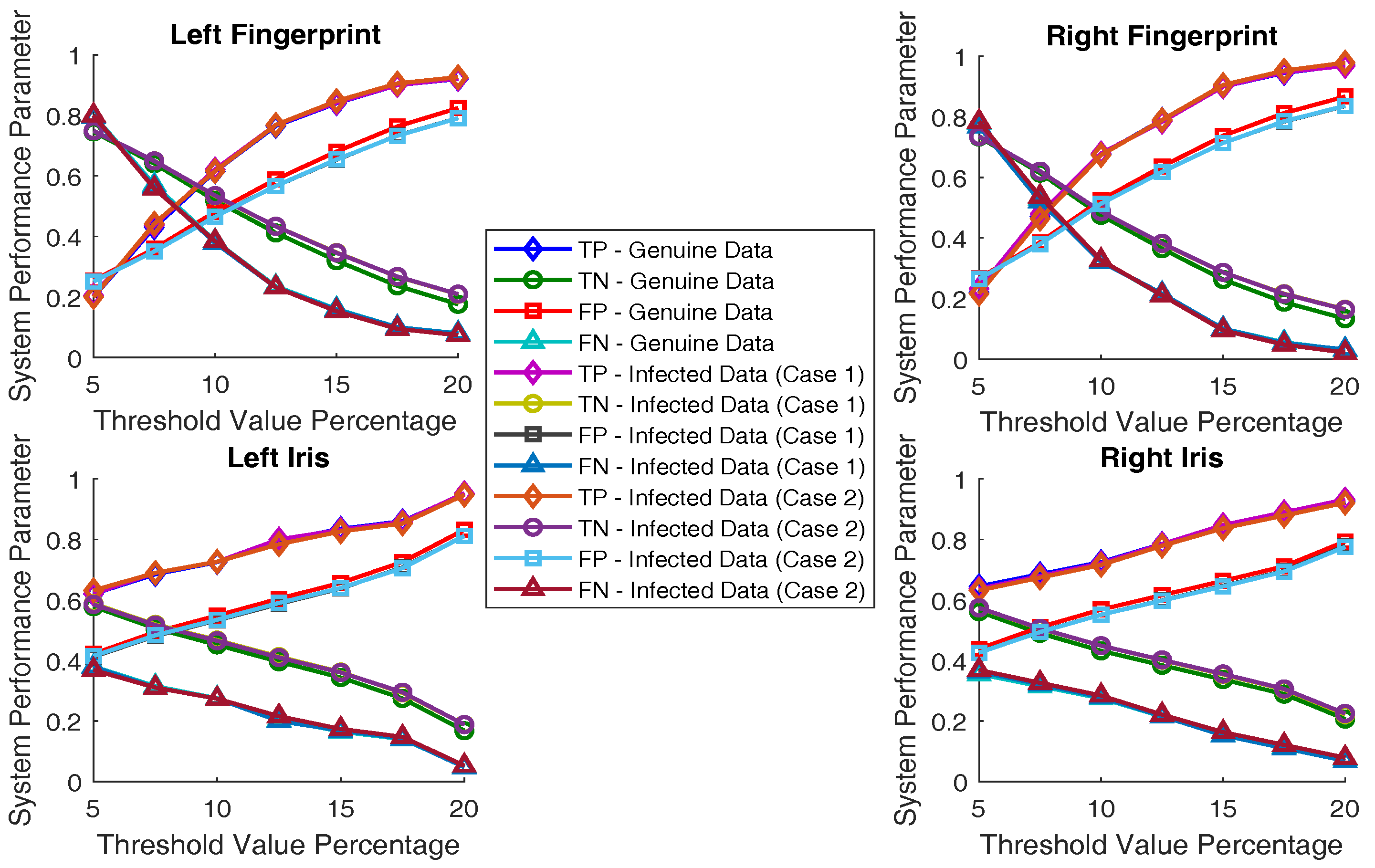
The results of the performance evaluation of the genuine and the infected biometric recognition system are shown in Table 2, Table 3 and Table 4. The average execution time of the biometric recognition system in evaluating a dataset is 36.9246 min. The most important parameter for security evaluation of the system is the false negative rate. As can be comprehended from Table 2, the system demonstrates a proper rejection capability at lower values of the threshold value. From the other side, the system performs poorly at accepting authentic data. As the threshold value becomes larger, the system operation becomes better at accepting valid data, while its ability for true rejection is degraded. Furthermore, the system performance is similar for all of the tested biometrics. More importantly, the system has a low false negative rate at higher values of the threshold value, which means it exhibits striking defense power in front of incorrect (or malicious) biometric data.
Table 3 and Table 4 show the system performance when the AES hardware module is infected. Since there are infected images among the datasets in these evaluations, the system demonstrates its defense capability, either through rejecting the infected images or filtering them for removal of an HT payload, if the rates for true rejection and true acceptance are increased. As can be seen from the results, the system proves its defense strength in confronting both infection cases. The graphical illustration of all these results is shown in Figure 10. As can be observed from the figure, there is growth in the correct acceptance and the correct rejection rates for the infection cases, which helps with the detection and localization of the Trojans.
For the hardware analysis, all the Verilog implementations of the hardware elements are synthesized using the Synopsys Armenia Educational Department (SAED) 32/28 nm generic library and the Synopsys Design Compiler tool. The clock period is set to 20 ns; the input delay is set to 1 ns; and the output delay is set to 1 ns. The synthesis results of the hardware elements of the biometric recognition system are shown in Table 5. According to the results, the hardware overheads of the Trojans are expressed as: HT 1, 0.88% for power consumption, 0% for critical path duration time and 0.82% for area; HT 2, 0.22% for power consumption, 0% for critical path duration time and 0.19% for area; HT 3, 1.46% for power consumption, 13.14% for critical path duration time and 0.68% for area; and HT 4, 1.45% for power consumption, 6.29% for critical path duration time and 1.01% for area. These overheads are relatively negligible considering all the cores within the chip. In order to compare the proposed system with its counterparts, two benchmark recognition systems are adopted from [11]. The fingerprint recognition system has a power consumption of 7.8862352 (mW), a critical path duration time of 891.2896 (ms) and an area of 329.5636 (mm2). The palm recognition system has a power consumption of 105,159.8520 (mW), a critical path duration time of 3656.1606 (ms) and an area of 2516.5824 (mm2). Our recognition system has higher values for all of the hardware parameters, but it has three main benefits: (i) performing the recognition process in two stages, which reduces the possibility of passing and accepting infected biometric data; (ii) performing a filtering process to eliminate the impact of a Hardware Trojan if applicable; and (iii) easier to locate an intrusion in the system due to a decussate and chaining hardware-software architecture. Meanwhile, our system has a conspicuously smaller hardware footprint in comparison to the existing exclusively hardware-based works, and its algorithm is computationally much simpler in comparison to the existing lightweight biometric recognition systems [12,13,14,15,16,17,18,19,20,21,22].
7. Conclusions
A cross-layer biometric recognition system with small computational complexity is studied in this work. The system has both software and hardware modules in a decussate and chaining structure. With this structure, it becomes easier to localize an intrusion in the system caused by an adversary. The system analyzes and security checks biometric data under investigation in two processing stages, which provides a higher level of defense strength. Regarding its hardware analysis, the main design parameters (power consumption, area and critical path duration time) of the hardware modules within the system are acceptable considering all hardware elements within the device. In order to further assess the recognition ability and the confrontation power of the system in front of malicious biometric data, four Hardware Trojans for the encryption unit positioned within the system are presented. The Trojans target different locations of the AES module namely the intermediate transformation round, the key expansion unit, the lookup table and the substitution-box. The HTs subvert the biometric data at different intensity levels with the aim of denial of service. According to the performance evaluation of the system, it is able to recognize the chosen biometrics, fingerprint and iris, with an acceptable level of accuracy. Furthermore, it has the potency to detect the maliciously-manipulated biometric data caused by the designed Hardware Trojans. The footprints of the designed HTs are negligible considering all the hardware elements within the victim chip. At last, studying cross-layer biometric recognition systems for surveillance applications is a relatively new research area, and more research and experiments are required to deliver more trustworthy security cameras for the IoT world.
Acknowledgments
We would like to thank Qutaiba Alasad and Milad Salem for reviewing the manuscript and providing valuable suggestions.
Author Contributions
S.T. proposed the threat and countermeasure models, implemented the circuits, performed the simulations, acquired and analyzed the experimental data and wrote the manuscript. J.-S.Y. provided technical feedback and reviewed the manuscript. S.T. and J.-S.Y. read and confirmed the final version of the manuscript.
Conflicts of Interest
The authors declare no conflict of interest.
References
- Keoh, S.L.; Kumar, S.S.; Tschofenig, H. Securing the internet of things: A standardization perspective. IEEE Internet Things J. 2014, 1, 265–275. [Google Scholar] [CrossRef]
- Bouchrika, I.; Mahfouf, Z.; Harrati, N. Re-identification: On the perception of human motion for surveillance and forensic applications. In Proceedings of the IEEE 17th International Conference on Sciences and Techniques of Automatic Control and Computer Engineering (STA), Sousse, Tunisia, 19–21 December 2016; pp. 312–316. [Google Scholar]
- Greenberg, I. From surveillance to torture: The evolution of US interrogation practices during the War on Terror. Secur. J. 2015, 28, 165–183. [Google Scholar] [CrossRef]
- Wayman, J.; Jain, A.; Maltoni, D.; Maio, D. An introduction to biometric authentication systems. In Biometric Systems; Springer: London, UK, 2005; pp. 1–20. [Google Scholar]
- Naderi, H.; Soleimani, B.H.; Matwin, S.; Araabi, B.N.; Soltanian-Zadeh, H. Fusing Iris, Palmprint and Fingerprint in a Multi-biometric Recognition System. In Proceedings of the 2016 13th Conference on IEEE Computer and Robot Vision (CRV), Victoria, BC, Canada, 1–3 June 2016; pp. 327–334. [Google Scholar]
- Ali, S.S.; Chakraborty, R.S.; Mukhopadhyay, D.; Bhunia, S. Multi-level attacks: An emerging security concern for cryptographic hardware. In Proceedings of the IEEE Design, Automation & Test in Europe Conference & Exhibition (DATE), Grenoble, France, 14–18 March 2011; pp. 1–4. [Google Scholar]
- Wu, L.; Wang, X.; Zhao, X.; Cheng, Y.; Su, D.; Chen, A.; Shi, Q.; Tehranipoor, M. AES design improvement towards information safety. In Proceedings of the 2016 IEEE International Symposium on Circuits and Systems (ISCAS), Montreal, QC, Canada, 22–25 May 2016; pp. 1706–1709. [Google Scholar]
- CASIA-FingerprintV5. 2010. Available online: http://biometrics.idealtest.org/dbDetailForUser.do?id=7 (accessed on 26 December 2017).
- CASIA-IrisV4. 2010. Available online: http://biometrics.idealtest.org/dbDetailForUser.do?id=4 (accessed on 26 December 2017).
- Tiny AES. 2015. Available online: tp://opencores.org/project (accessed on 12 December 2017).
- Gesture Recognition Hardware (Verilog Implementation). 2012. Available online: https://github.com (accessed on 19 December 2017).
- Athale, S.S.; Patil, D.; Deshpande, P.; Dandawate, Y.H. Hardware implementation of palm vein biometric modality for access control in multilayered security system. Procedia Comput. Sci. 2015, 58, 492–498. [Google Scholar] [CrossRef]
- Yeo, H.S.; Lee, B.G.; Lim, H. Hand tracking and gesture recognition system for human-computer interaction using low-cost hardware. Multimed. Tools Appl. 2015, 74, 2687–2715. [Google Scholar] [CrossRef]
- Pham, V.K.; Nguyen, H.D.; Nguyen-Khac, T.A.; Tran, M.T. Apply lightweight recognition algorithms in optical music recognition. In Proceedings of the Seventh International Conference on Machine Vision (ICMV 2014), Milan, Italy, 19–21 November 2014; International Society for Optics and Photonics: Bellingham, WA, USA, 2015; Volume 9445, p. 944504. [Google Scholar]
- McGuffey, C.; Liu, C.; Schuckers, S. Implementation and optimization of a biometric cryptosystem using iris recognition. In Proceedings of the Biometric and Surveillance Technology for Human and Activity Identification XII, Baltimore, MD, USA, 14 May 2015; International Society for Optics and Photonics: Bellingham, WA, USA, 2015; Volume 9457, p. 945702. [Google Scholar]
- Sardar, S.; Babu, K.A. Hardware Implementation of Real-Time, High Performance, RCE-NN Based Face Recognition System. In Proceedings of the 2014 27th International Conference on VLSI Design and 2014 13th International Conference on Embedded Systems, Mumbai, India, 5–9 January 2014; pp. 174–179. [Google Scholar]
- Kang, P.Y.; Chen, Y.P.; Jeng, M.J. Lane recognition system implemented by a full hardware design. In Proceedings of the 2014 International Symposium on Next-Generation Electronics (ISNE), Tao-Yuan, Taiwan, 7–10 May 2014; pp. 1–3. [Google Scholar]
- Czúni, L.; Kiss, P.J.; Lipovits, Á.; Gál, M. Lightweight mobile object recognition. In Proceedings of the 2014 IEEE International Conference on Image Processing (ICIP), Paris, France, 27–30 October 2014; pp. 3426–3428. [Google Scholar]
- Mahale, G.; Mahale, H.; Goel, A.; Nandy, S.; Bhattacharya, S.; Narayan, R. Hardware solution for real-time face recognition. In Proceedings of the 2015 28th International Conference on VLSI Design (VLSID), Bangalore, India, 3–7 January 2015; pp. 81–86. [Google Scholar]
- Lee, E.; Lee, S.S.; Hwang, Y.; Jang, S.J. Hardware implementation of fast traffic sign recognition for intelligent vehicle system. In Proceedings of the 2016 International SoC Design Conference (ISOCC), Jeju, Korea, 23–26 October 2016; pp. 161–162. [Google Scholar]
- Lee, S.S.; Lee, E.; Hwang, Y.; Jang, S.J. Low-complexity hardware architecture of traffic sign recognition with IHSL color space for advanced driver assistance systems. In Proceedings of the IEEE International Conference on Consumer Electronics-Asia (ICCE-Asia), Seoul, Korea, 26–28 October 2016; pp. 1–2. [Google Scholar]
- López-García, M.; Ramos-Lara, R.; Miguel-Hurtado, O.; Cantó-Navarro, E. Embedded system for biometric online signature verification. IEEE Trans. Ind. Inform. 2014, 10, 491–501. [Google Scholar] [CrossRef]
Figure 1.
The architecture of the cross-layer biometric recognition system.

Figure 2.
Attack 1: The hardware Trojan circuit for malicious manipulation of the output of the intermediate transformation round.
Figure 2.
Attack 1: The hardware Trojan circuit for malicious manipulation of the output of the intermediate transformation round.

Figure 3.
Attack 2: the Hardware Trojan circuit for malicious manipulation of the functionality of the key expansion unit.
Figure 3.
Attack 2: the Hardware Trojan circuit for malicious manipulation of the functionality of the key expansion unit.

Figure 4.
Attack 3: The Hardware Trojan circuit for malicious manipulation of the input of the table boxes (T-Boxes ) within the lookup table.
Figure 4.
Attack 3: The Hardware Trojan circuit for malicious manipulation of the input of the table boxes (T-Boxes ) within the lookup table.

Figure 5.
Attack 4: The Hardware Trojan circuit for malicious manipulation of the output of the substitution-box (S-Box).
Figure 5.
Attack 4: The Hardware Trojan circuit for malicious manipulation of the output of the substitution-box (S-Box).
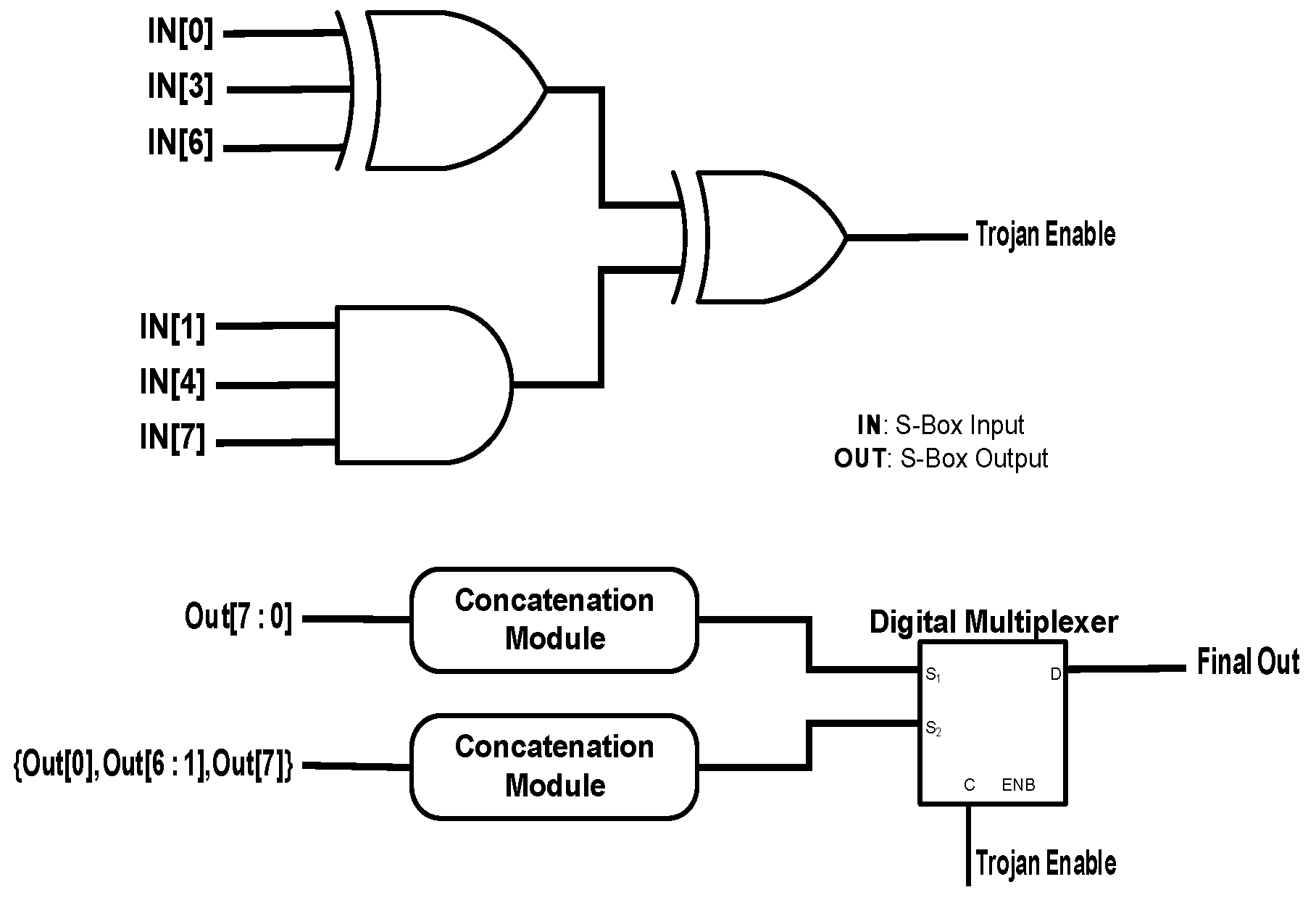
Figure 6.
Attack Fingerprint Example (1): The payloads of the Hardware Trojans in sabotaging the image prints of the left thumb.
Figure 6.
Attack Fingerprint Example (1): The payloads of the Hardware Trojans in sabotaging the image prints of the left thumb.

Figure 7.
Attack Fingerprint Example (2): The payloads of the Hardware Trojans in sabotaging the image prints of the right thumb.
Figure 7.
Attack Fingerprint Example (2): The payloads of the Hardware Trojans in sabotaging the image prints of the right thumb.
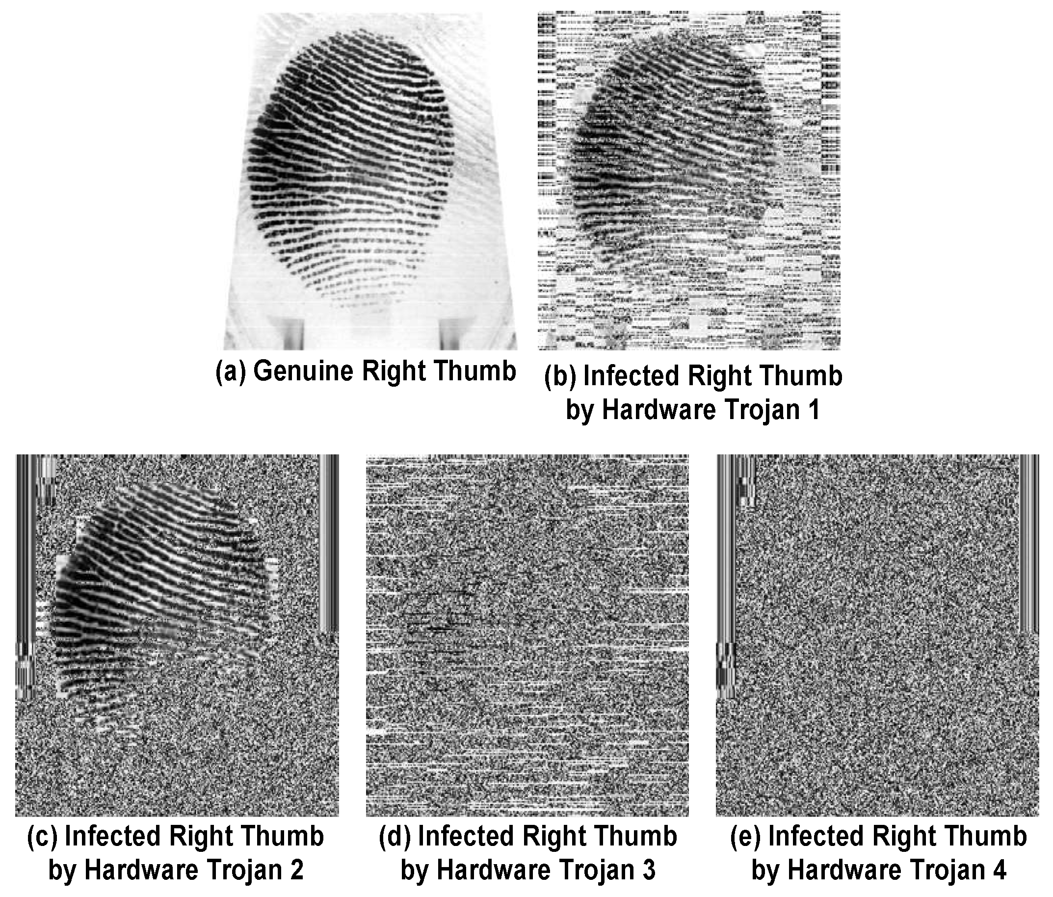
Figure 8.
Attack Iris Example (1): The payloads of the Hardware Trojans in sabotaging the image prints of the left iris.
Figure 8.
Attack Iris Example (1): The payloads of the Hardware Trojans in sabotaging the image prints of the left iris.

Figure 9.
Attack Iris Example (2): The payloads of the Hardware Trojans in sabotaging the image prints of the right iris.
Figure 9.
Attack Iris Example (2): The payloads of the Hardware Trojans in sabotaging the image prints of the right iris.

Figure 10.
The graphical analysis of the system performance for different biometric data.


Table 1.
The description of infecting the biometric datasets.
| Biometric Data | Subject | Infection Case 1 | Infection Case 2 | Biometric Data | Subject | Infection Case 1 | Infection Case 2 | |||
|---|---|---|---|---|---|---|---|---|---|---|
| Left Thumb | 5 | Trojan 4 | Trojan 3 | Left Iris | 2 | Trojan 4 | Trojan 4 | |||
| 10 | Trojan 3 | Trojan 2 | 7 | Trojan 1 | Trojan 4 | |||||
| 15 | Trojan 1 | Trojan 4 | 12 | Trojan 3 | Trojan 2 | |||||
| 20 | Trojan 1 | Trojan 2 | 17 | Trojan 2 | Trojan 2 | |||||
| 25 | Trojan 1 | Trojan 2 | 22 | Trojan 3 | Trojan 1 | |||||
| 30 | Trojan 2 | Trojan 2 | 27 | Trojan 4 | Trojan 3 | |||||
| 35 | Trojan 3 | Trojan 3 | 32 | Trojan 4 | Trojan 3 | |||||
| 40 | Trojan 4 | Trojan 3 | 37 | Trojan 4 | Trojan 3 | |||||
| 45 | Trojan 3 | Trojan 4 | 42 | Trojan 2 | Trojan 3 | |||||
| 50 | Trojan 2 | Trojan 4 | 47 | Trojan 1 | Trojan 3 | |||||
| Right Thumb | 1 | Trojan 2 | Trojan 4 | Right Iris | 3 | Trojan 1 | Trojan 1 | |||
| 6 | Trojan 2 | Trojan 4 | 8 | Trojan 2 | Trojan 2 | |||||
| 11 | Trojan 2 | Trojan 4 | 13 | Trojan 4 | Trojan 2 | |||||
| 16 | Trojan 1 | Trojan 3 | 18 | Trojan 4 | Trojan 3 | |||||
| 21 | Trojan 4 | Trojan 2 | 23 | Trojan 3 | Trojan 3 | |||||
| 26 | Trojan 4 | Trojan 2 | 28 | Trojan 3 | Trojan 2 | |||||
| 31 | Trojan 3 | Trojan 1 | 33 | Trojan 1 | Trojan 2 | |||||
| 36 | Trojan 3 | Trojan 1 | 38 | Trojan 2 | Trojan 1 | |||||
| 41 | Trojan 2 | Trojan 2 | 43 | Trojan 4 | Trojan 1 | |||||
| 46 | Trojan 1 | Trojan 3 | 48 | Trojan 3 | Trojan 4 |
Table 2.
Performance Evaluation Results (1): The performance evaluation of the healthy cross-layer biometric recognition system for four biometric datasets.
Table 2.
Performance Evaluation Results (1): The performance evaluation of the healthy cross-layer biometric recognition system for four biometric datasets.
| Biometric Data | Percentage of Threshold Value (%) | True Positive Rate () | True Negative Rate () | False Positive Rate () | False Negative Rate () |
|---|---|---|---|---|---|
| Left Thumb | 5 | 0.2000 | 0.7453 | 0.2547 | 0.8000 |
| 7.5 | 0.4300 | 0.6402 | 0.3598 | 0.5700 | |
| 10 | 0.6150 | 0.5189 | 0.4811 | 0.3850 | |
| 12.5 | 0.7650 | 0.4117 | 0.5883 | 0.2350 | |
| 15 | 0.8400 | 0.3198 | 0.6802 | 0.1600 | |
| 17.5 | 0.9000 | 0.2367 | 0.7633 | 0.1000 | |
| 20 | 0.9200 | 0.1759 | 0.8241 | 0.0800 | |
| Right Thumb | 5 | 0.2200 | 0.7333 | 0.2667 | 0.7800 |
| 7.5 | 0.4700 | 0.6142 | 0.3858 | 0.5300 | |
| 10 | 0.6750 | 0.4747 | 0.5253 | 0.3250 | |
| 12.5 | 0.7900 | 0.3641 | 0.6359 | 0.2100 | |
| 15 | 0.9000 | 0.2627 | 0.7373 | 0.1000 | |
| 17.5 | 0.9450 | 0.1876 | 0.8124 | 0.0550 | |
| 20 | 0.9700 | 0.1330 | 0.8670 | 0.0300 | |
| Left Iris | 20 | 0.6200 | 0.5777 | 0.4223 | 0.3800 |
| 25 | 0.6850 | 0.5060 | 0.4940 | 0.3150 | |
| 30 | 0.7250 | 0.4515 | 0.5485 | 0.2750 | |
| 35 | 0.7950 | 0.3958 | 0.6042 | 0.2050 | |
| 40 | 0.8350 | 0.3437 | 0.6563 | 0.1650 | |
| 45 | 0.8600 | 0.2745 | 0.7255 | 0.1400 | |
| 50 | 0.9500 | 0.1679 | 0.8321 | 0.0500 | |
| Right Iris | 20 | 0.6450 | 0.5615 | 0.4385 | 0.3550 |
| 25 | 0.6850 | 0.4898 | 0.5102 | 0.3150 | |
| 30 | 0.7250 | 0.4318 | 0.5682 | 0.2750 | |
| 35 | 0.7850 | 0.3841 | 0.6159 | 0.2150 | |
| 40 | 0.8450 | 0.3371 | 0.6629 | 0.1550 | |
| 45 | 0.8850 | 0.2889 | 0.7111 | 0.1150 | |
| 50 | 0.9250 | 0.2065 | 0.7935 | 0.0750 |
Table 3.
Performance Evaluation Results (2): The performance evaluation of the infected cross-layer biometric recognition system for four biometric datasets.
Table 3.
Performance Evaluation Results (2): The performance evaluation of the infected cross-layer biometric recognition system for four biometric datasets.
| Biometric Data | Percentage of Threshold Value (%) | True Positive Rate () | True Negative Rate () | False Positive Rate () | False Negative Rate () |
|---|---|---|---|---|---|
| Left Thumb | 5 | 0.2053 | 0.7488 | 0.2512 | 0.7947 |
| 7.5 | 0.4368 | 0.6496 | 0.3504 | 0.5632 | |
| 10 | 0.6211 | 0.5340 | 0.4660 | 0.3789 | |
| 12.5 | 0.7684 | 0.4335 | 0.5665 | 0.2316 | |
| 15 | 0.8421 | 0.3468 | 0.6532 | 0.1579 | |
| 17.5 | 0.9000 | 0.2669 | 0.7331 | 0.1000 | |
| 20 | 0.9211 | 0.2090 | 0.7910 | 0.0789 | |
| Right Thumb | 5 | 0.2316 | 0.7356 | 0.2644 | 0.7684 |
| 7.5 | 0.4789 | 0.6203 | 0.3797 | 0.5211 | |
| 10 | 0.6789 | 0.4871 | 0.5129 | 0.3211 | |
| 12.5 | 0.7842 | 0.3813 | 0.6187 | 0.2158 | |
| 15 | 0.9000 | 0.2862 | 0.7138 | 0.1000 | |
| 17.5 | 0.9474 | 0.2156 | 0.7844 | 0.0526 | |
| 20 | 0.9684 | 0.1643 | 0.8357 | 0.0316 | |
| Left Iris | 20 | 0.6211 | 0.5877 | 0.4123 | 0.3789 |
| 25 | 0.6895 | 0.5191 | 0.4809 | 0.3105 | |
| 30 | 0.7263 | 0.4674 | 0.5326 | 0.2737 | |
| 35 | 0.8000 | 0.4129 | 0.5871 | 0.2000 | |
| 40 | 0.8316 | 0.3618 | 0.6382 | 0.1684 | |
| 45 | 0.8579 | 0.2927 | 0.7073 | 0.1421 | |
| 50 | 0.9526 | 0.1886 | 0.8114 | 0.0474 | |
| Right Iris | 20 | 0.6368 | 0.5738 | 0.4262 | 0.3632 |
| 25 | 0.6789 | 0.5050 | 0.4950 | 0.3211 | |
| 30 | 0.7211 | 0.4489 | 0.5511 | 0.2789 | |
| 35 | 0.7842 | 0.4010 | 0.5990 | 0.2158 | |
| 40 | 0.8474 | 0.3536 | 0.6464 | 0.1526 | |
| 45 | 0.8895 | 0.3044 | 0.6956 | 0.1105 | |
| 50 | 0.9316 | 0.2217 | 0.7783 | 0.0684 |
Table 4.
Performance Evaluation Results (3): The performance evaluation of the infected cross-layer biometric recognition system for four biometric datasets.
Table 4.
Performance Evaluation Results (3): The performance evaluation of the infected cross-layer biometric recognition system for four biometric datasets.
| Biometric Data | Percentage of Threshold Value (%) | True Positive Rate () | True Negative Rate () | False Positive Rate () | False Negative Rate () |
|---|---|---|---|---|---|
| Left Thumb | 5 | 0.2000 | 0.7487 | 0.2513 | 0.8000 |
| 7.5 | 0.4421 | 0.6494 | 0.3506 | 0.5579 | |
| 10 | 0.6158 | 0.5349 | 0.4651 | 0.3842 | |
| 12.5 | 0.7684 | 0.4334 | 0.5666 | 0.2316 | |
| 15 | 0.8474 | 0.3458 | 0.6542 | 0.1526 | |
| 17.5 | 0.9053 | 0.2675 | 0.7325 | 0.0947 | |
| 20 | 0.9263 | 0.2094 | 0.7906 | 0.0737 | |
| Right Thumb | 5 | 0.2158 | 0.7354 | 0.2646 | 0.7842 |
| 7.5 | 0.4632 | 0.6205 | 0.3795 | 0.5368 | |
| 10 | 0.6737 | 0.4869 | 0.5131 | 0.3263 | |
| 12.5 | 0.7895 | 0.3820 | 0.6180 | 0.2105 | |
| 15 | 0.9053 | 0.2862 | 0.7138 | 0.0947 | |
| 17.5 | 0.9526 | 0.2148 | 0.7852 | 0.0474 | |
| 20 | 0.9789 | 0.1635 | 0.8365 | 0.0211 | |
| Left Iris | 20 | 0.6316 | 0.5853 | 0.4147 | 0.3684 |
| 25 | 0.6895 | 0.5168 | 0.4832 | 0.3105 | |
| 30 | 0.7263 | 0.4652 | 0.5348 | 0.2737 | |
| 35 | 0.7842 | 0.4098 | 0.5902 | 0.2158 | |
| 40 | 0.8263 | 0.3604 | 0.6396 | 0.1737 | |
| 45 | 0.8526 | 0.2950 | 0.7050 | 0.1474 | |
| 50 | 0.9474 | 0.1883 | 0.8117 | 0.0526 | |
| Right Iris | 20 | 0.6316 | 0.5740 | 0.4260 | 0.3684 |
| 25 | 0.6737 | 0.5059 | 0.4941 | 0.3263 | |
| 30 | 0.7158 | 0.4488 | 0.5512 | 0.2842 | |
| 35 | 0.7789 | 0.4020 | 0.5980 | 0.2211 | |
| 40 | 0.8368 | 0.3554 | 0.6446 | 0.1632 | |
| 45 | 0.8789 | 0.3061 | 0.6939 | 0.1211 | |
| 50 | 0.9211 | 0.2250 | 0.7750 | 0.0789 |
Table 5.
Hardware evaluation results: The synthesis results of the hardware elements of the healthy and the infected cross-layer biometric recognition system.
Table 5.
Hardware evaluation results: The synthesis results of the hardware elements of the healthy and the infected cross-layer biometric recognition system.
| User Role | Hardware Module | Power Consumption (mW) | Critical Path Duration Time (ms) | Area (mm2) |
|---|---|---|---|---|
| Sender Side | Genuine AES Encryption Unit | 32.8160 | 0.0175 | 1.0059 |
| Infected AES Encryption Unit 1 | 33.1040 | 0.0175 | 1.0141 | |
| Infected AES Encryption Unit 2 | 32.8880 | 0.0175 | 1.0078 | |
| Infected AES Encryption Unit 3 | 33.2940 | 0.0198 | 1.0127 | |
| Infected AES Encryption Unit 4 | 33.2930 | 0.0186 | 1.0161 | |
| Receiver Side | Number of Maximum Value | 235.4176 | 8.5811 | 8.8064 |
| Average Value | 151.1424 | 11.5302 | 5.5296 | |
| Median Value | 997.7856 | 57.0163 | 34.4064 | |
| Number of Minimum Value | 236.1344 | 8.5811 | 8.8064 | |
| Mode Value | 6345.5232 | 224.9523 | 250.6752 | |
| Standard Deviation | 43,832.1152 | 2434.1709 | 1748.1728 | |
| Number of Values >High Threshold Value | 76.5952 | 8.4070 | 2.7648 | |
| Number of Values <Low Threshold Value | 103.3216 | 8.4070 | 3.6864 | |
| Kurtosis | 2188.9024 | 10,277.5194 | 8921.088 | |
| Skewness | 88,165.5808 | 10,469.7037 | 3735.552 | |
| Manhattan Norm | 773.3248 | 179.5686 | 31.1296 | |
| Euclidean Distance | 2421.5552 | 207.5853 | 81.92 | |
| First-Stage Comparison Unit | 0.1319 | 0.0166 | 0.0045 | |
| Mean Filtering | 629.9648 | 67.5021 | 22.9376 | |
| Average Euclidean Distance | 7750.0416 | 262.8608 | 239.8208 | |
| Average Cityblock/Manhattan Distance | 2633.3184 | 337.8995 | 90.7264 | |
| Average Hamming Distance | 958.0544 | 80.1792 | 35.0208 | |
| Average Chebyshev Distance | 792.576 | 53.3914 | 23.552 | |
| Second-Stage Comparison Unit | 66.7188 | 0.0111 | 0.0025 |
© 2018 by the authors. Licensee MDPI, Basel, Switzerland. This article is an open access article distributed under the terms and conditions of the Creative Commons Attribution (CC BY) license (http://creativecommons.org/licenses/by/4.0/).
Share and Cite
MDPI and ACS Style
Taheri, S.; Yuan, J.-S. A Cross-Layer Biometric Recognition System for Mobile IoT Devices. Electronics 2018, 7, 26. https://doi.org/10.3390/electronics7020026
AMA Style
Taheri S, Yuan J-S. A Cross-Layer Biometric Recognition System for Mobile IoT Devices. Electronics. 2018; 7(2):26. https://doi.org/10.3390/electronics7020026
Chicago/Turabian StyleTaheri, Shayan, and Jiann-Shiun Yuan. 2018. "A Cross-Layer Biometric Recognition System for Mobile IoT Devices" Electronics 7, no. 2: 26. https://doi.org/10.3390/electronics7020026
Note that from the first issue of 2016, this journal uses article numbers instead of page numbers. See further details here.