Performance Comparison of Geobroadcast Strategies for Winding Roads


1
Artificial Intelligence Department, Escuela Técnica Superior de Ingeniería de Sistemas Informáticos (ETSISI), Universidad Politécnica de Madrid, 28031 Madrid, Spain
2
University Institute for Automobile Research (INSIA), Universidad Politécnica de Madrid, Campus Sur UPM, Carretera de Valencia km.7, 28031 Madrid, Spain
*
Author to whom correspondence should be addressed.
Electronics 2018, 7(3), 32; https://doi.org/10.3390/electronics7030032
Submission received: 16 December 2017
/
Revised: 22 February 2018
/
Accepted: 1 March 2018
/
Published: 3 March 2018
(This article belongs to the Special Issue Machine Learning and Embedded Computing in Advanced Driver Assistance Systems (ADAS))
Abstract
:Vehicle-to-X (V2X) communications allow real-time information sharing between vehicles and Roadside Units (RSUs). These kinds of technologies allow for the improvement of road safety and can be used in combination with other systems. Advanced Driver Assistance Systems (ADAS) are an example and can be used along with V2X communications to improve performance and enable Cooperative Systems. A key element of vehicular communications is that the information transmitted through the network is always linked to a GPS position related to origin and destination (GeoNetworking protocol) in order to adjust the data broadcast to the dynamic road environment needs. In this paper, we present the implementation and development of Institute for Automobile Research (INSIA) V2X communication modules that follow the European vehicular networking standards in a close curve in a winding road where poor visibility causes a risk to the safety of road users. The technology chosen to support these communications is ETSI ITS-G5, which has the capability to enable specific services that support GeoNetworking protocols, specifically the Geobroadcast (GBC) algorithm. These functionalities have been implemented and validated in a real environment in order to demonstrate the performance of the communication devices in real V2V (Vehicle-to-Vehicle) and V2I (Vehicle-to-Infrastructure) situations. GBC messages are also compared with two different configurations of emission area. A comparison with/without RSU modules in critical areas of the road with previous knowledge of the road cartography has also been made.
1. Introduction
Vehicular ad hoc networks (VANETs) allow communication between vehicles, which are considered as nodes in the system. Due to the limited range of the communication channel (1 km [1]) they are considered short-range networks and their physical communications protocol is defined in the standard ETSI-G5 [2], which is the European standard equivalent to IEEE 802.11p [3]. The standards define the operation and implementation that the communications between vehicles must follow for the transmission of packages in the 5.9 GHz band (802.11p protocol).
As these networks work in variable environments and with high mobility, they require specific routing algorithms which are defined in the standards. These algorithms can manage information routing among the network nodes (vehicles and Roadside Units -RSUs-) to guarantee data availability in real time. Also, these kinds of services can enable different cooperative systems [4,5].
Thus, the geographical positioning of each network node is essential for its configuration. Given the nature of these communication networks, the most common type of transmission used is broadcast protocols. However, one of the classical limitations of broadcast-based communications is the appearance of situations such as network saturation or flooding—particularly dangerous in this case [6]. The routing algorithms of VANETs define geographical boundaries to limit the broadcast of messages [7] that are used to specify their relevance while these kinds of boundaries also prevent flooding effects.
Thus, three GeoNetworking protocol configurations that must be supported in vehicular operations are defined [8]:
- Geounicast: conveys a message to the vehicle that is in a particular geographic position;
- Geobroadcast: conveys a message to all vehicles that are in a particular geographic area;
- Geoanycast: conveys a message to the nearest vehicle that is in a particular geographic area.
These operations are supported by specific GeoRouting algorithms. To guarantee the correct performance of all these algorithms, each network node maintains a neighbor location table. This table contains a time-stamped address, position, and speed for ITS (Intelligent Transport Systems) stations (nodes) in its vicinity. GeoNetworking forwarding algorithms use this neighbor location table to make forwarding decisions [9].
Although the algorithms are defined and differentiated in the standard, there are multiple changes that have been presented to improve their efficiency. Korkmaz et al. [10] presented their own model of Geobroadcast known as Urban Multihop broadcast (UMB). Since vehicle mobility is high and vehicles leave and enter the network frequently, the topology of this network changes quickly. Therefore, the UMB protocol is designed to operate without exchanging location information among nearby nodes.
Furthermore, there are other works that consider an improved Geobroadcast algorithm, such as BROADCOOM [11]. This protocol is based on Geographical Routing and improves the quality of inter-vehicular broadcast communications by keeping a low load on the network.
Another improvement for a Geobroadcast algorithm is the proposal by Yu’Chun Liu et al. [12]. They proposed a Software-Defined Network (SDN) architecture for Geobroadcast in VANETs, and showed an implementation of a system that automatically manages the geographic position of each node. The results of the implementation were shown using a simulation in OpenNet.
In order to reduce the number of accidents and improve road safety, several European projects have arisen, such as GEONET and COMPASS4D. The COMPASS4D project proposed the Energy Efficiency Intersection (EEI) which uses a two-way communication system to optimize the communication of vehicles at an intersection. Another work of COMPASS4D is the Road Hazard Warning which uses communication systems between vehicles to provide a safe warnings system to the vehicles. Likewise, GEONET uses communications between vehicles to send safety messages over IPv6 in certain areas.
Some of the most novel works done with VANETs are based on simulations, like those of Tobias Queck et al. [13] where simulations of different scenarios were presented, or S. Djahel et al. [14], who showed a simulation to reduce traffic congestion. In another case, Victor Sandonis et al. [15] presented an adaptation of Proxy Mobile IPv6 (PMIPv6) with ETSI TC ITS GeoNetworking protocols to improve the overall performance. Liu Zhenuy et al. [16] proposed a communications module OBU (On Board Unit) through 802.11p communications to implement a safety system for pedestrians and vehicles. However, a few works have more advanced systems, such as [17], which implemented communications modules with the IEEE 1609.3 standard and IEEE 802.11p.
Despite the algorithms described above, we have focused on incorporating the Geobroadcast algorithm into the communication module because it adapts better to the test conditions. These modules have been implemented using GeoNetworking algorithms and multihop behavior following European standards. For this purpose, we have demonstrated its full operation with tests in a real and complex environment, understanding as complex a close curve in a winding road where poor visibility causes a risk to the safety of road users. ETSI EN 636-4-1 [18] defines the rules that communication modules follow when receiving Geobroadcast packages. The Geobroadcast algorithm transmits its messages to a specific geographical area; this area of interest is defined in the same standard where three possible types are listed: circular, rectangular, or ellipsoidal. The ETSI EN 302 931 [19] specifies the characteristics of the areas in greater depth as well as the equations for each one.
However, the standards are still in an interim state, without the specification of some facilities layers or the security layer. However, even today there are many manufacturers that have some V2X products available on the market. Those products are not designed under a closed specification and are subject to change. In this context, a proprietary V2X communication module has been designed at the Institute for Automobile Research (INSIA) in order to support the research and deployment of V2X technology. This unit supports the current European standards in V2X communications and has passed interoperability tests in the AUTOCITS project [20] with other manufacturers (Yogoko and Cohda communication modules).
In this paper the development of the INSIA-V2X communications module is presented, including hardware and software, open to be adapted to the necessities of any cooperative systems to be developed. It includes validation testing in hazardous areas, on rural roads, specifically in complex scenarios. Thus, its operation is demonstrated in real environments like rural winding roads with adverse situations for communications and it is shown to continue operating through different configurations of emission and incorporating an RSU module in points of difficult diffusion. Two different ways of issuing Geobroadcast (GBC) messages are compared, focusing the emission area on different objectives and the same scenario with/without using a RSU module.
The following work is divided into five sections. The first section, V2X Communication System, shows the hardware and software used in each of the modules. In the section following (Implementation), the Geobroadcast algorithm used is shown in greater depth. The third section (Tests and Results) shows the results obtained during the tests performed. In the last two sections (Discussion and Conclusion), the results obtained are evaluated, comparing different configurations.
2. V2X Communication System
2.1. V2X Communication Modules
The communication modules are the INSIA-V2X (Figure 1) [21], developed internally at INSIA. Likewise, DSRC (Dedicated Short-Range Communications) INSIA-V2X modules are based on an AR9220 chipset that uses the ath9k modified driver to allow 802.11p bands. This card is configured to work in the 5855–5925 GHz bands.
The operating system that incorporates the modules is Debian Wheezy with kernel version 3.19.0. The kernel has been configured to allow Outside the Context of a BSS -Basic Service Set- (OCB) mode and the ath9k driver. The ath9k driver has been modified to allow the 802.11p protocol.
Each INSIA-V2X module includes the Global Navigation Satellite System NV08C-CSM chipset. It is an integrated GLONASS + GPS + GALILEO + SBAS satellite navigation receiver for use in various applications demanding low cost (~380€ per module), low power consumption, and uncompromised performance.
2.2. Ad Hoc Network Protocol
In 1977, due to the need to create a standard capable of encompassing all computer networks, a subcommittee (SC16) was created to address Open System Interconnection (OSI) [22]. In 1997 this model was adapted to run in wireless environments, becoming the IEEE 802.11 protocol; later, in 2010, its amended version was published as the IEEE 802.11p standard to run in vehicular environments. The European mirror of this protocol is the ETSI ITS-G5.
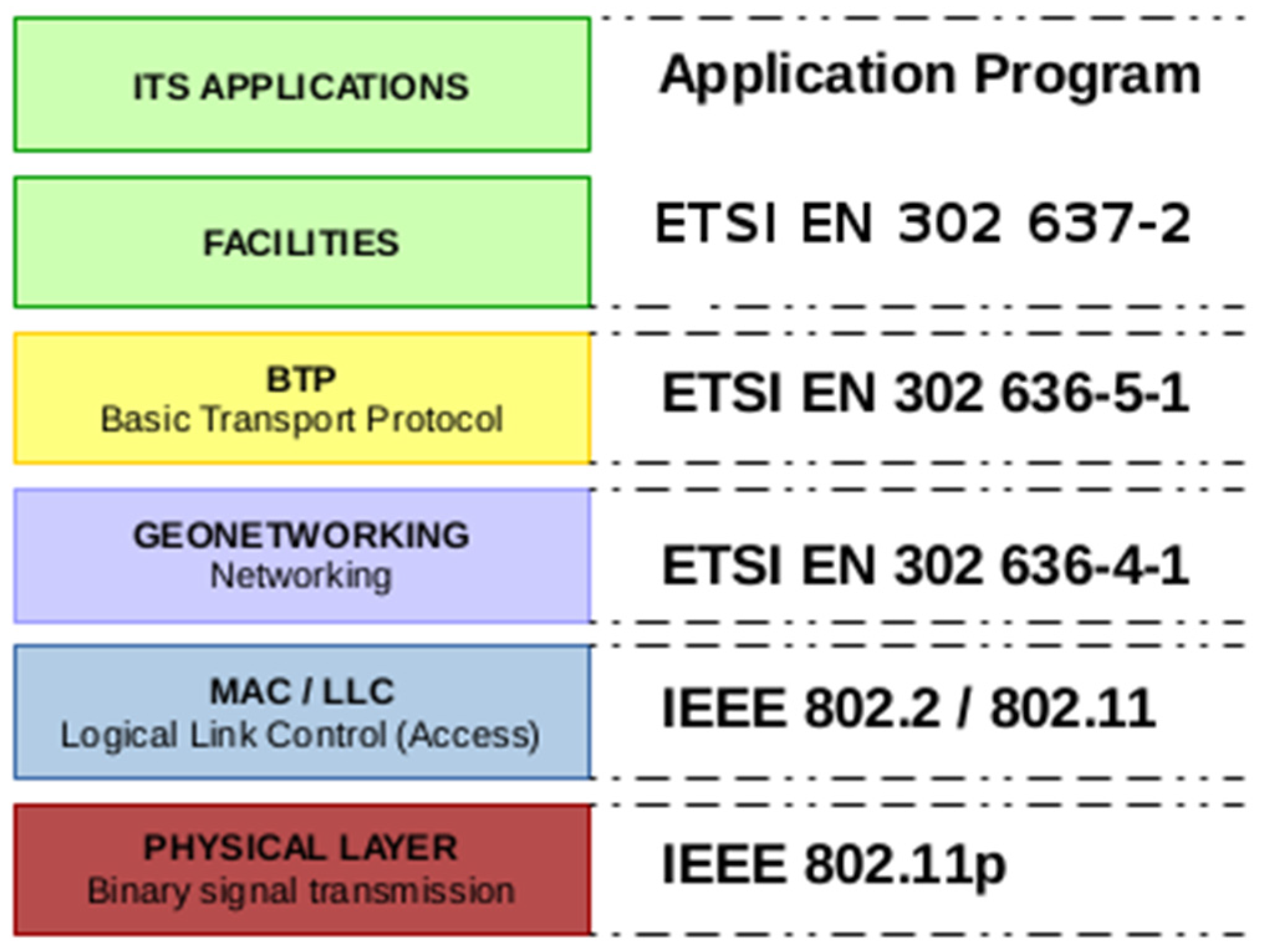
The philosophy of vehicular communications (V2X) is that each vehicle and RSU element is considered as a network dynamic node and each node can receive and relay messages from the network. The OSI model for communications is set according to the ETSI EN 636-4-1 [18] (Figure 2).
As shown in Figure 2, the Logical Link Control (LLC) corresponds to the data link layer for local area networks. The LLC layer is responsible for packing the frames with the destination MAC (Medium Access Control); upon receiving a message, it checks its MAC identifier and sends it up to the GeoNetworking layer. The network layer includes the GeoNetworking capabilities where Geobroadcast messages are processed. Inside the GeoNetworking layer, the information of the module and nearby nodes is stored in a database. Each entry in the database contains the node’s GPS position as well as the time, error, speed, etc. The protocol sends beacons from time to time to communicate its information to the rest of the system.
The Basic Transport Protocol (BTP) layer defined in ETSI [23] has also been implemented in the DRSC INSIA-V2X modules, and enables communication with external devices or applications. The link with high-level safety or efficiency applications is possible through the BTP protocol, enabling the use of this module as a V2X network access provider for vehicles and RSUs.
3. Implementation
The implementation of a DSRC INSIA-V2X module that follows the ETSI EN 636-4-1 [18] standard is presented. In the standard, different communication algorithms are defined, such as Geoanycast, Geounicast, Topology Scope Broadcast, Geobroadcast, etc. In this paper we have focused on the operation of the Geobroadcast algorithm and calculation of the defined areas for each of the possible cases.
In Figure 3, the scheme of the different logical units that operate in the presented V2X modules is shown. In the figure, the colors are associated with the layers of the OSI model in [22]. In the center of the figure is shown the Local Position Vector and Location Table responsible for storing local information and the known nodes of the module, respectively.
The Man Packet Handling box processes the messages received by the LLC layer or the GeoNetworking box itself. In the first case, the Man Packet Handling evaluates the message, stores the information in the Location Table, and forwards it according to the protocol. In the second case, it receives the message with the data module through the GeoNetworking layer, and then packs and sends it according to the protocol (Beacon, GeoUnicast (GUC), GeoBroadcast (GBC), Topology Scope Broadcast (TSB), or Location Service (LS)).
In addition to the GeoNetworking features of the message through the GBC algorithm, the GeoNetworking layer has been designed to make a controlled and directed diffusion of the data to a limited geographical area to avoid network congestion. When treating a message, the GBC logical unit must calculate whether the node belongs to the emitting area. If the node is in the emitting area, the module manages the message and records it in the Location Table to have the last position of the node.
If the node is outside the emitting area, the next optimal jump to forward the message must be calculated. Standard ETSI EN 636-4-1 [18] defines the greedy algorithm which calculates the optimal node (closest) to send the message.
The standard defines how to analyze the area of interest and transmit the GBC messages. These formulas are applied to Cartesian Coordinates, which are not intended for the global positioning system as they begin to cause problems, especially in the rectangular and ellipsoidal area.
In the case of INSIA V2X modules, the calculation has been done using polar coordinates to simplify operations. Then, the distance between two points in geographic coordinates given the central point of the area and the position of the node is given by Equation (1).
The Harversine function [24] calculates the distance between two geographic points with the Harversine Equation (2) where the P0 and Pn parameters are the geographic positions of the focal and node points, respectively. In the case of the circle, the Harversine function is enough, but for the rectangle and the ellipse it is necessary to calculate the Northing angle to which the area is oriented.
The ITS management layer is responsible for constantly updating the module data obtained from can-BUS and GPS. The BTP layer is responsible for sending the information of the module to the connected applications. In this way, it communicates with the GN data program from which it requests information.
4. Tests and Results
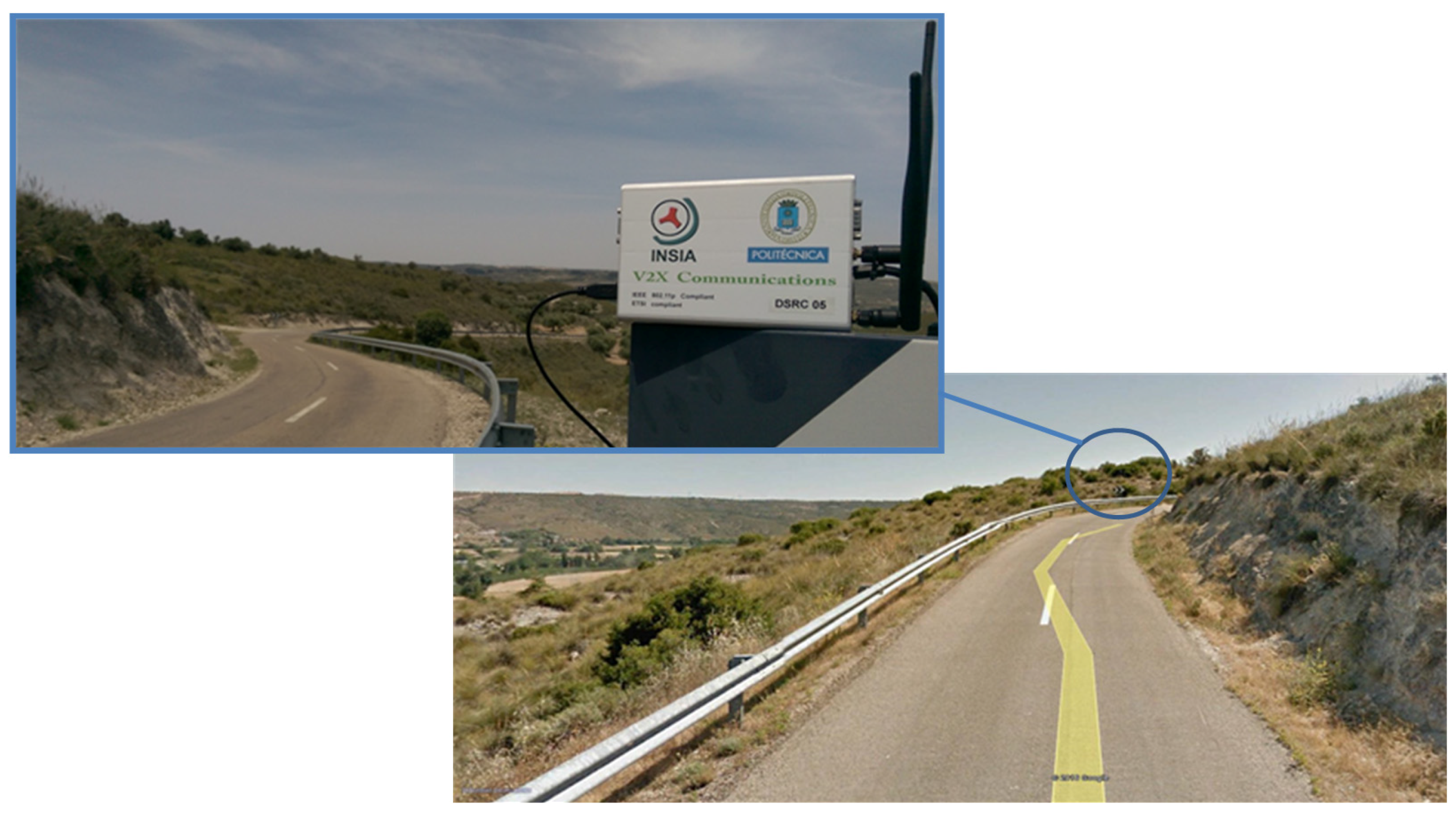
In the tests carried out, different situations were considered to test the communication modules and the GeoNetworking algorithms; for this case, only the Geobroadcast algorithm has been tested because it adapts better to the characteristics of the environment. The tests were performed in the town of Morata de Tajuña in the Madrid Region (Spain) on a road outside the urban core that includes bends which lack visibility. Figure 4 shows one of these bends at ground level for a better appreciation of the situation, including a detail of a traffic sign at the midpoint on the outside of the bend where the RSU communications module was installed. In addition, the fact that the road is very narrow should also be highlighted while the dividing line simply marks the center of the track.
In this environment, it is possible to test the two main behaviors of the V2X modules: V2V and V2I. The former involves sending and receiving data directly from two moving vehicles in a determined geographical area to feed cooperative systems. The latter involves the use of an intermediate relay node to support multihop behavior when there is no direct link between the vehicles in the geographic destination area. In this second case, an additional RSU module was added.
The INSIA vehicles used were a Peugeot 307 and a Kymco Super Dink 125i motorcycle, each one equipped with a DRSC INSIA-V2X Communications Module. The devices used as data sources were a Motorola Nexus 6 smartphone with Android 5.1.1 and a BQ Curie 2 Quad Core tablet with Android 4.2.2. The smartphone was placed on the motorcycle due to its smaller size. Each device runs an application (app) developed to interact with the DSRC module and send its own warning messages. This app allows the sending of specific GBC messages to the onboard communications module. It also receives messages that are addressed to the module and is able to extract the information stored in the connected module.
Eight experiments were performed in total (Table 1). Those experiments are divided into two blocks. In the first block, four experiments are shown comparing two different emission centers for the area of the GBC algorithm. In the second block, the same experiments were carried out including an RSU module.
In each one of these four cases, only the motorcycle emits GBC messages. The experiments performed to compare the GBC algorithm emission area present two situations: the GBC emission area focuses on the position of the motorcycle, and the focus of the area of emission is in the center of the poor visibility bend. As a function of the cooperative system’s necessities, the messages can switch from one configuration to another. Finally, to observe the operation of the algorithm in each configuration, the car may remain stationary or be in motion for each type of emission.
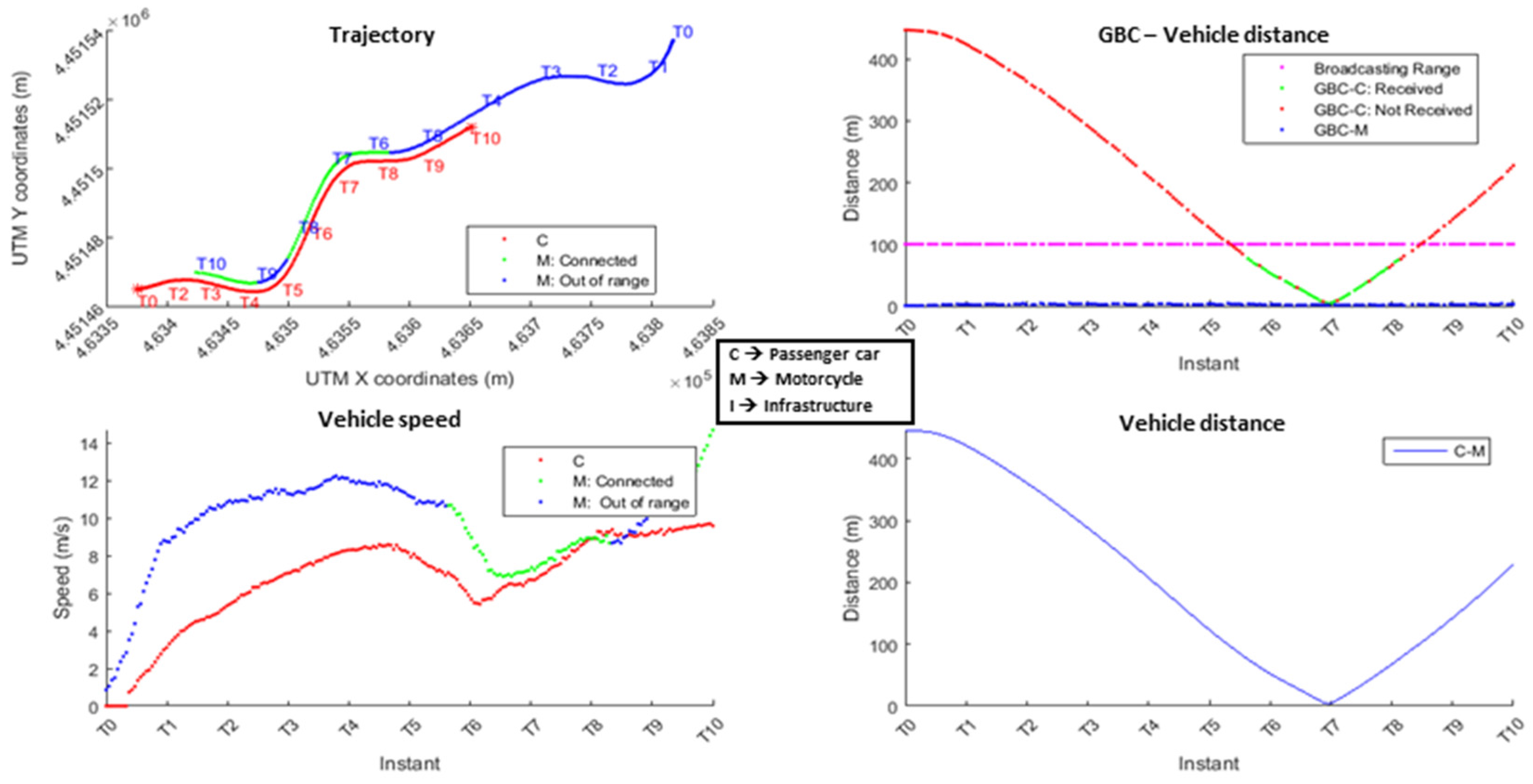
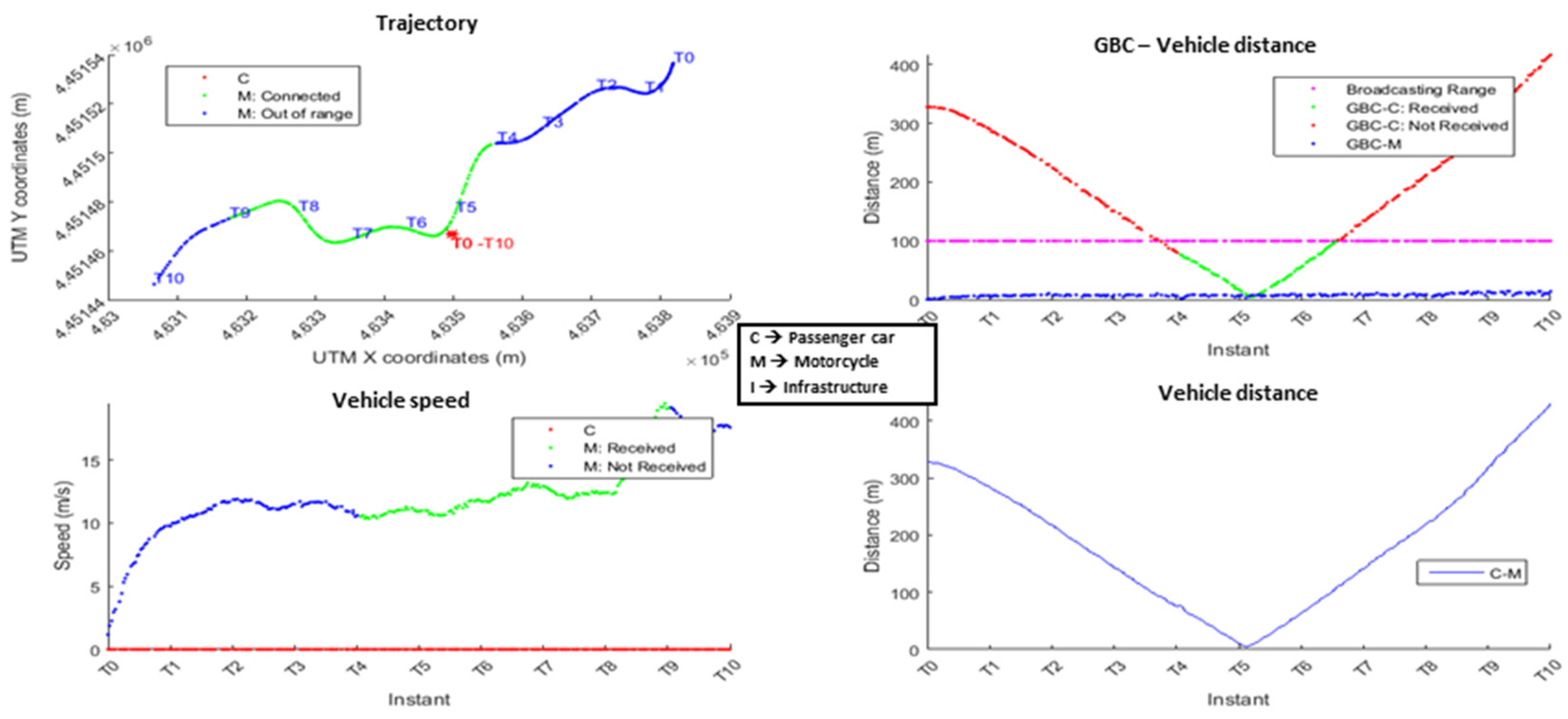
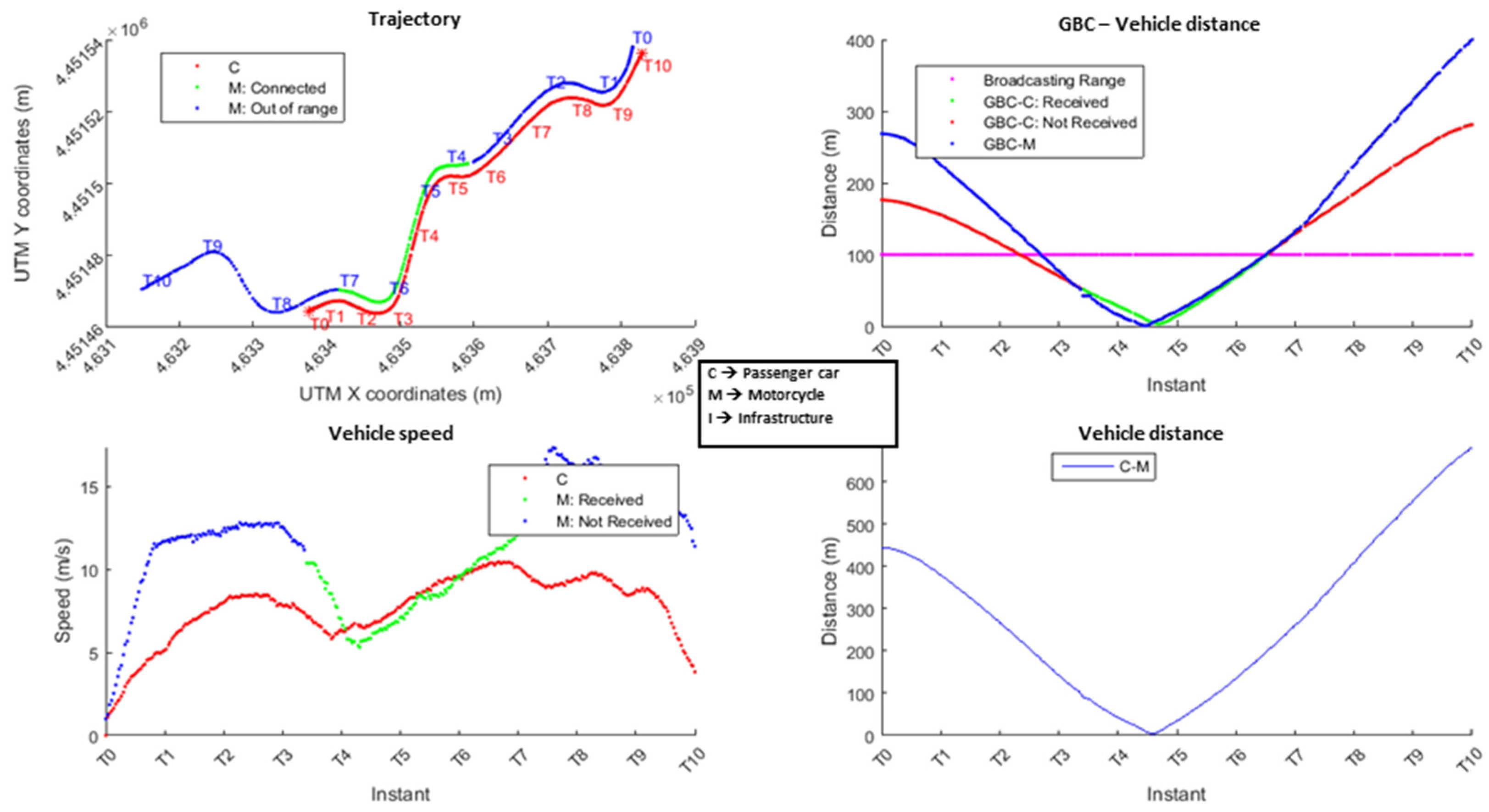
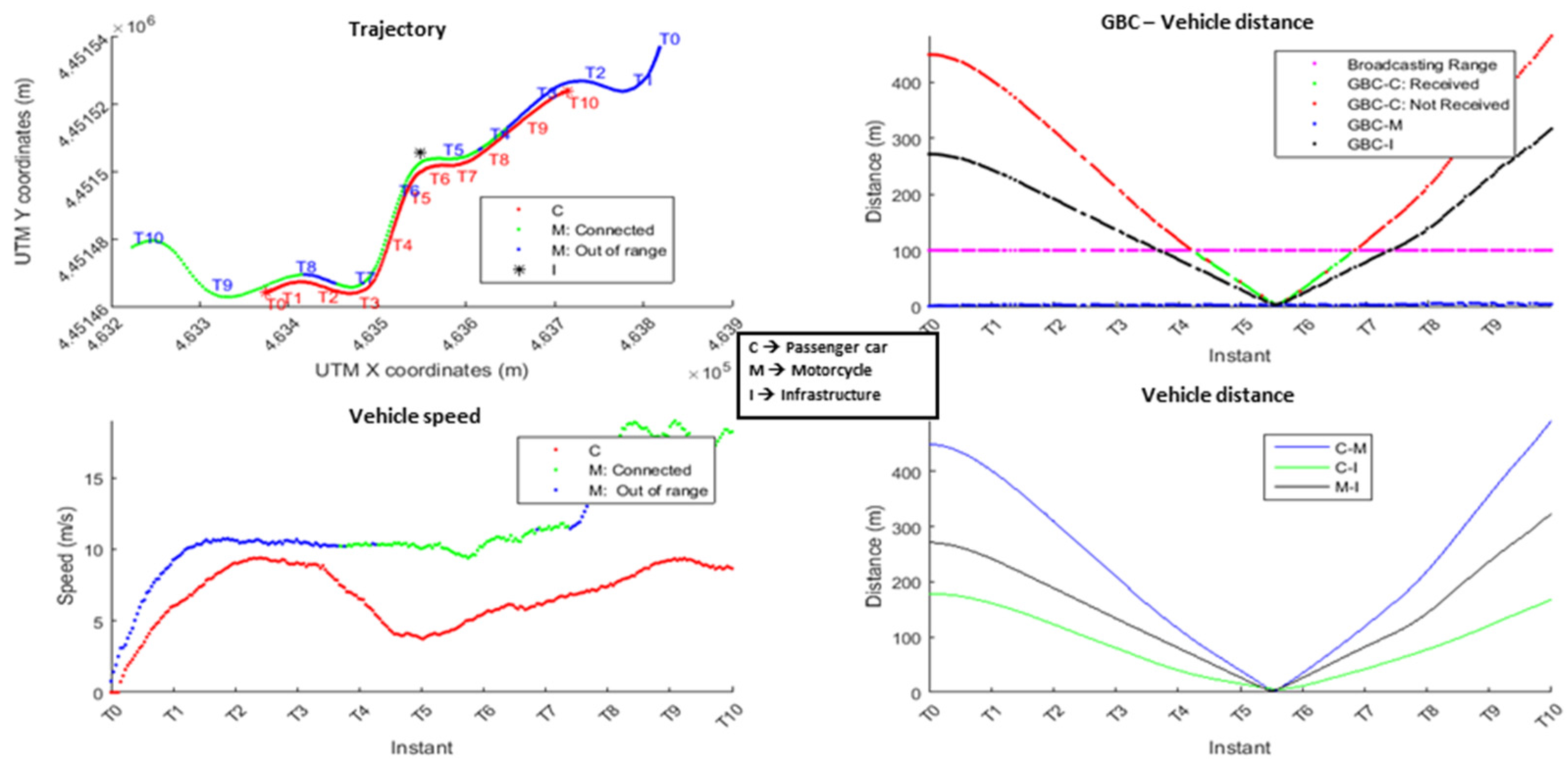
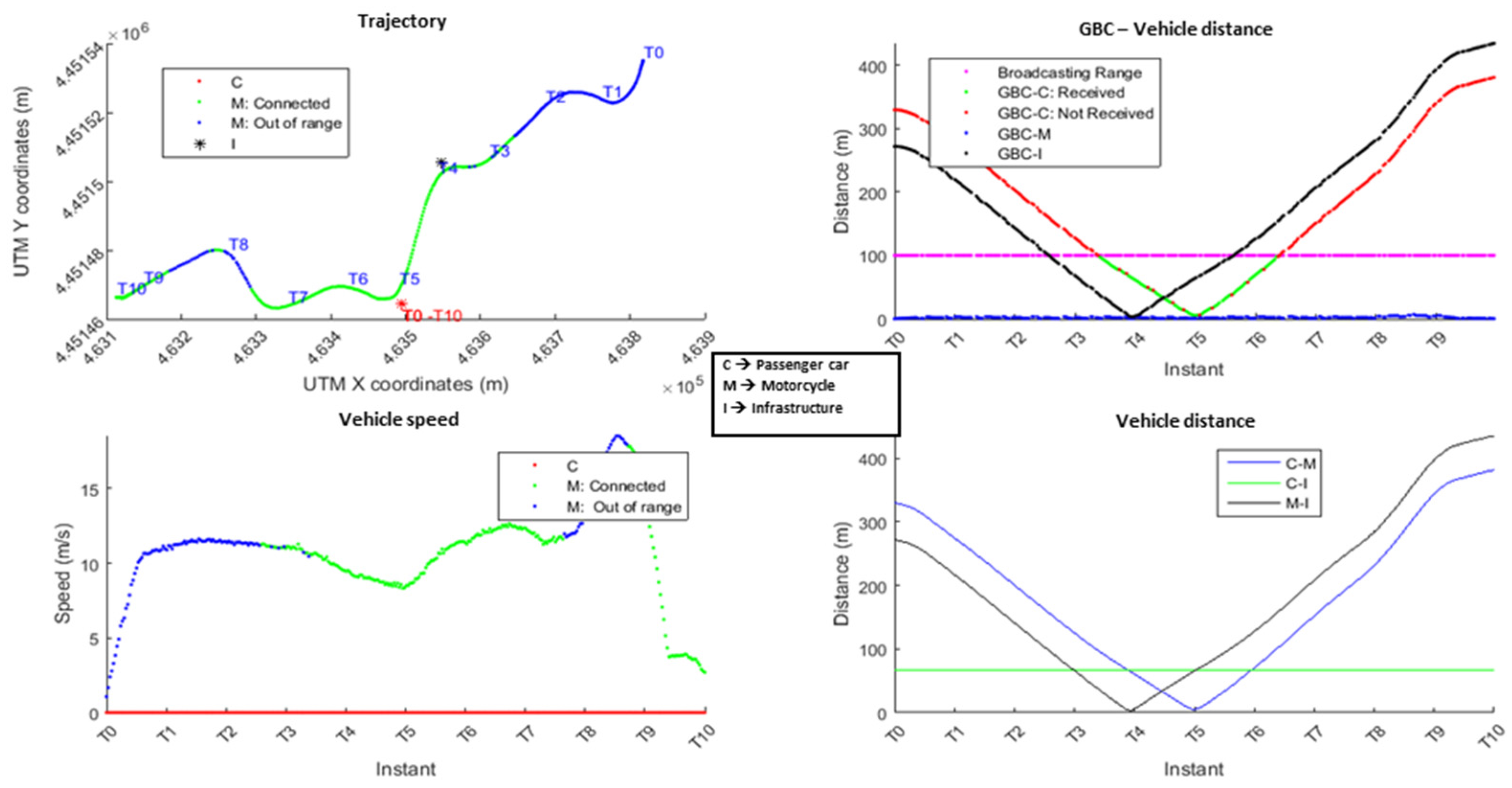
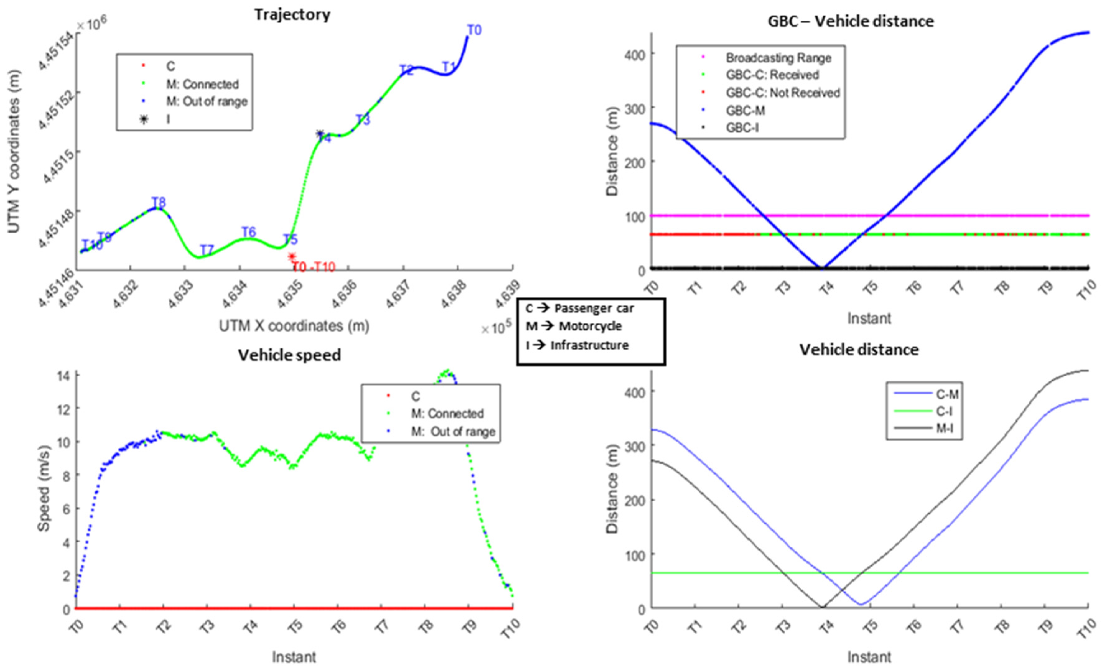
The results of each test are shown as graphs for a better understanding, presented in Figure 5, Figure 6, Figure 7, Figure 8, Figure 9, Figure 10, Figure 11 and Figure 12. In each case, four graphs are used:
- Trajectory (top left): This graph shows the trajectory of the car (C) and the motorcycle (M) in UTM (Universal Transverse Mercator) coordinates (meters). The green line represents when both vehicles are connected (C knows M’s position) and the blue one when there is no connection between them. This disconnection may be caused because the car was out of the area defined in the GBC or because this message has not been received. The black point represents the position of the RSU module.
- GBC–Vehicle distance (top right): This graph shows the distance in meters between each vehicle with respect to the center of the GBC reception area. The green line represents the distance when the motorcycle has a connection with the car. The purple line represents the range of the GBC area, set at 100 m from the center in every case. The blue line is the evolution of the distance to the center of the motorcycle during the test and the red line is the evolution of this distance of the car. Finally, the red line represents the distance from the RSU module (when available) to the center of the reception area of the GBC.
- Vehicle speed (bottom left): This graph displays the speed of each vehicle in m/s. The red line represents the speed of the motorcycle and the blue line the speed of the car. Similar to the previous graphs, the color of the motorcycle line changes to green when there is communication with the car.
- Vehicle distance (bottom right): This graph shows the distance in meters between the vehicles and the RSU. The blue line represents the distance between the car and the motorcycle. The black line is the distance between the motorcycle and the RSU and the green line is the distance between the car and the RSU.
In the experiments the time has been represented as Ti in order to synchronize the trajectories of both vehicles. Time T0 is considered when the experiment begins and T10 when it finishes. For all tests performed, the message transmission frequency was 4 Hz (4 frames per second).
4.1. Validation without RSU Module
In these tests, two different types of configuration for GBC messages were tested. Therefore, for each type of configuration a test was performed with a static car and another simulating a situation of real driving. The four tests were configured as follows:
- Test 1 (Figure 5): The circular area 100 m in radius was focused on the motorcycle and the car remained immobile throughout the test.
- Test 2 (Figure 6): The configuration of the GBC messages was the same as for Test 1 but the car was moving in the opposite direction.
- Test 3 (Figure 7): The circular area 100 m in radius was focused on the vertex of the curve and the car remained immobile throughout the test.
- Test 4 (Figure 8): The configuration of the GBC messages was the same as for Test 3 but the car was moving in the opposite direction.
With the results obtained, it can be seen that the car takes time to obtain information about the motorcycle. This is due to the fact that the terrain orography prevents communication between modules. Even with the orography, both drivers are warned about the position of the other vehicle before they have eye contact. However, this warning is not carried out enough in advance and this fact justifies placing a module as an RSU to solve this problem.
4.2. Validation with RSU Module
In this section, the same cases as in the previous one are presented but including a module as an RSU. This verifies how the V2I communications affect the system and if they are able to improve the delay of the previous cases. The four tests were configured as follows:
- Test 1B (Figure 9): The circular area 100 m in radius was focused on the motorcycle and the car remained immobile throughout the test.
- Test 2B (Figure 10): The configuration of the GBC messages was the same as for Test 1 but the car was moving in the opposite direction.
- Test 3B (Figure 11): The circular area 100 m in radius was focused on the vertex of the curve and the car remained immobile throughout the test.
- Test 4B (Figure 12): The configuration of the GBC messages was the same as for Test 3 but the car was moving in the opposite direction.
With the results obtained, a significant improvement can be verified in all cases. In the GBC–Vehicle distance graph, it can be seen that there is no loss of frames. At the moment the vehicle is within the area of interest, it receives information from the motorcycle. Therefore, the RSU module allows problems in communications due to orography to be solved, acting as a relay for the GBC messages by placing its broadcast area in zones where there is no node.
In these tests performed with RSU modules, the differences between the two GBC message settings can be seen. In the configuration where we fix the center of the emission area at the vertex of the curve, information of the motorcycle is obtained in advance. This advantage allows the driver of the car to anticipate any situation with more time.
The problem associated with this type of configuration is that the situation of the road must be known in order to accurately position the broadcast areas. This inconvenience can only be solved by having the cartography.
5. Discussion
During the tests, we collected all the packets emitted by the motorcycle, regardless of whether they were received by the car in or out of the GBC circular reception area. The information obtained from the reception of these messages allows us to analyze the behavior of the network, maximum range, effective range, position of the vehicles, or transmission time in the different configurations. Table 2 shows the comparison of the range in the 8 tests. The distance is presented as a straight line between the vehicle and the motorcycle when they connect for the first time, whether or not they are in the GBC coverage range.
Results shown in Table 2 corroborate the conclusions described in the previous section, verifying the improved behavior of centering the GBC destination area in the middle of the poor visibility bend. This guarantees coverage of messages as soon as possible when an emitting vehicle is approaching the dangerous area. It is also important to remark that the inclusion of intermediate relay RSU modules has no influence on the transmission latency of the messages. This means that the developed INSIA-V2X communication modules do not introduce delays into the system.
Analysis of the GBC packets (sent and received) to obtain a packet loss rate was also done to validate the performance of the system. These results are shown in Table 3 as well as the time for which the vehicles were connected during the tests.
Keep in mind that the packet delivery rate emitted by the motorcycle is 4 Hz (4 frames per second) and most of the packets not received are mainly due to the orography.
The sent packets column of Table 3 corresponds to the total GBC packets sent from when the test started until it was finished. The next column corresponds to the number of data packets sent by the motorcycle when the car was in the GBC circular reception area and the fourth column represents the GBC packets received by the car when it was within the GBC circular reception area. In addition, these packages were received and processed by the car to be within the destination area of transmission. Finally, the last column represents the time during which both vehicles were connected, interchanging messages.
The results shown in Table 3 are discussed separately in order to understand the differences between each test:
- Test 1A: The rate of non-received packets during the test is high—about 25%. This is because the car remains in the same position throughout the test and does not receive messages from the motorcycle until it is within the line of sight of the bend, although the car is in the GBC range. Figure 5 shows that these losses occur mainly at the beginning and end of the entry into the GBC range, as the two vehicles are driven on the low visibility curve.
- Test 1B: By including the RSU module in the test, the number of packets that are not received is reduced by more than half, producing only sporadic packet losses; as can be seen in Figure 6, the car messages are received when the motorcycle enters the coverage area.
- Test 2A: In this case, the rate of non-received packets is also high, at around 27%. As in Test 1A, orography plays an important role in the test and the car takes longer to receive the first data from the motorcycle (it is at the opposite side of the curve) and there is no direct line of sight with the car. This data loss occurs at the beginning and at the end of the test, as shown in Figure 7.
- Test 2B: When including the RSU module, the number of packets that are not received is reduced by more than half, with the appearance of sporadic losses as shown in Figure 8.
- Test 3A: By selecting the center of the GBC range at the apex of the curve, the results are apparently worse since the rate of non-received packets during the test is 59%. This test is the one with the highest number of packets not received by the car. This is because the configuration of the GBC message causes the emission area to focus on the curve and, therefore, the car will always be within the broadcast area of the total packets emitted from the start of the trial.
- Test 3B: An RSU module is included, solving a part of the communication problem of Test 3A. The number of packets not received by the car is considerably reduced, although it is still high because they are calculated from the beginning of the trial, since the car is always stopped within the coverage area. As shown in Figure 10, the time during which the car receives messages is higher than for any of the above tests, as the car receives data packets at the same instant that the motorcycle has the direct vision line to the RSU module.
- Test 4A: In this case, the rate of non-received messages is high—around 51%—for the same reason as in Test 3A. As in other tests, the orography prevents communication between vehicles and this causes many messages to not reach the car.
- Test 4B: Finally, the best results occur with configuration 4B, where the rate of non-received packets is 4%. This gives the best result because the RSU module allows more efficient communication. It increases the range of communications and the car is in the coverage area when the motorcycle is connected with the RSU module, receiving the data. This setting is most appropriate when deploying a cooperative system and ensures that there will be maximum connectivity at the moment when there is greatest risk of an accident.
It is an obvious conclusion that the best configuration of V2X architecture is when an RSU module is installed at the roadside. When RSUs are used, the number of received packets increases; this is due to the fact that the RSU retransmits the packets it receives and it may be the case that messages are repeated. However, the standard indicates that when a module receives a duplicate of a package it has already received, this will be wasted. There is a second factor that definitively influences the performance of this configuration: the position of the center of Geobroadcast areas. As shown in the figures, the location of this center in the critical zone of the RSU definitively improves the performance and range of the communication. Furthermore, a priori knowledge of the location of this critical area is necessary to enable this configuration and this information is outside the GBC standard, depending only on the C-ITS applications. C-ITS applications should then have digital cartography data about the critical areas where the location of the GBC centers will improve their functionality.
6. Conclusions
In this paper, we have shown the correct operation of DSRC modules with the Geobroadcast algorithm in a close curve in a winding road where poor visibility causes a risk to the safety of road users. Communications were made through the 802.11p protocol and tested using real instrumented vehicles. With the results obtained in the tests, the system was shown to be robust and well functioning.
The work carried out in [25] was complemented by testing the Geobroadcast algorithm and the system under a situation of scarce coverage for communications. In addition, there is a problem derived from centering the area of emission in a curve in which no node is found. Two different emitting configurations were provided for this situation by focusing the area on a vehicle or including an RSU module in the vertex of the curve.
The system was tested in a scenario where the orography plays an important role in the communications, as detailed in [26]. With the orography situation chosen, it is not possible to predict which would be the best way to center the emission area if the road conditions are not previously known. In this case, it is demonstrated that the solution is given by placing an RSU module.
As reflected in the tests performed, it is important to know the conditions of the road in order to choose the best strategy of emission and configuration of the system. The RSUs are an important part of the system, preventing blind spots in communications, but it is not the only tool, as demonstrated in this paper. Therefore, this paper has demonstrated two different ways of issuing GBC messages as well as the addition of RSU communication modules in critical risky areas.
As the tests have been oriented to a specific scenario, there are aspects of the communication modules that have not been tested. In future work, the facilities layer defined in the standard could be developed and tested as to how its operation affects the system. In addition, it should be noted that it would be subject to study as to how scalability affects the system with a different number of modules emitting at different frequencies.
Acknowledgments
This work has received the support of the Spanish Ministerio de Economía y Competitividad MINECO (TRA2016-78886-C3-3-R) and Madrid Region Excellence Network SEGVAUTO-TRIES (S2013/MIT-2713).
Author Contributions
All authors contributed to the paper. E. Talavera and J. J. Anaya developed the communications modules. O. Gómez prepared the tests. F. Jimenez and J. E. Naranjo proposed the system and the scenario and analyzed the final results.
Conflicts of Interest
The authors declare no conflict of interest.
References
- Jakubiak, J.; Koucheryavy, Y. State of the art and research challenges for VANETS. In Proceedings of the 5th IEEE Consumer Communications and Networking Conference, Las Vegas, NV, USA, 10–12 January 2008; p. 912. [Google Scholar]
- Intelligent Transport Systems (ITS). European Profile Standard for the Physical and Medium Access Control Layer of Intelligent Transport Systems Operating in the 5 GHz Frequency Band, v1.1.0 edition; European Telecommunications Standards Institute: Sophia Antipolis Cedex, France, 2009.
- 802.11p Local and Metropolitan Area Networks-Specific Requirements-part11: Wireless Lan Medium Access Control (mac) and Physical Layer (phy) Specifications Amendment 6: Wireless Access in Vehicular Environments; Technical Report; IEEE: Piscataway, NJ, USA, 2010.
- Hussain, R.; Son, J.; Eun, H.; Kim, S.; Oh, H. Traffic information system: A lightweight geocast-based piggybacking strategy for cooperative awareness in VANET. In Proceedings of the 2013 IEEE International Conference on Consumer Electronics (ICCE), Las Vegas, NV, USA, 11–14 January 2013; pp. 614–615. [Google Scholar]
- Atéchian, T.; Torbey, Z.; Bennani, N.; Brunie, L. CoFFee: Cooperative and inFrastructure-Free peer-to-peer system for VANET. In Proceedings of the 2009 9th International Conference on Intelligent Transport Systems Telecommunications, Lille, France, 20–22 October 2009; pp. 510–515. [Google Scholar]
- Prasetijo, A.B.; Alwakeel, S.S.; Altwaijry, H.A. Effects of VANET’s attributes on network performance. In Proceedings of the 2014 1st International Conference on Information Technology, Computer and Electrical Engineering (ICITACEE), Semarang, Indonesia, 8–9 November 2014; pp. 303–308. [Google Scholar]
- Meneguette, R.; Villas, L. An Autonomic Algorithm for Data Dissemination in Vehicular Ad Hoc Networks. IEEE Lat. Am. Trans. 2014, 12, 430–435. [Google Scholar] [CrossRef]
- Festag, A. Cooperative intelligent transport systems standards in Europe. IEEE Commun. Mag. 2014, 52, 166–172. [Google Scholar] [CrossRef]
- Observations on GeoNetworking, Document HTG1&3-3; Version: 2012-11-12, EU-US ITS Task Force, Standards Harmonization Working Group, Harmonization Task Groups 1 & 3; U.S. Department of Transportation: Washington, DC, USA, 2011.
- Korkmaz, G.; Ekici, E.; Özgüner, U. Urban multi-hop broadcast protocol for inter-vehicle communication systems. In Proceedings of the 1st ACM International Workshop on Vehicular Ad Hoc Networks, VANET ’04, New York, NY, USA, 1 October 2004; pp. 76–85. [Google Scholar]
- Durresi, M.; Durresi, A.; Barolli, L. Emergency broadcast protocol for intervehicle communications. In Proceedings of the 11th International Conference on Parallel and Distributed Systems, Fukuoka, Japan, 20–22 July 2005; Volume 2, pp. 402–406. [Google Scholar]
- Liu, Y.C.; Chen, C.; Chakraborty, S. A Software Defined Network architecture for GeoBroadcast in VANETs2. In Proceedings of the 2015 IEEE International Conference on Communications (ICC), London, UK, 8–12 June 2015; pp. 6559–6564. [Google Scholar]
- Queck, T.; Schünemann, B.; Radusch, I.; Meinel, C. Realistic Simulation of V2X Communication Scenarios. In Proceedings of the IEEE Asia-Pacific Services Computing Conference, Yilan, Taiwan, 9–12 December 2008. [Google Scholar]
- Djahel, S.; Jabeur, N.; Barrett, R.; Murphy, J. Toward V2I communication technology-based solution for reducing road traffic congestion in smart cities. In Proceedings of the 2015 International Symposium on Networks, Computers and Communications (ISNCC), Hammamet, Tunisia, 13–15 May 2015; pp. 1–6. [Google Scholar]
- Sandonis, V.; Calderon, M.; Soto, I.; Bernardos, C.J. Design and performance evaluation of a PMIPv6 solution for geonetworking-based VANETs. Ad Hoc Netw. 2013, 11, 2069–2082. [Google Scholar] [CrossRef]
- Zhenyu, L.; Lin, P.; Konglin, Z.; Lin, Z. Design and evaluation of V2X communication system for vehicle and pedestrian safety. J. China Univ. Posts Telecommun. 2015, 22, 18–26. [Google Scholar] [CrossRef]
- Meng, Z.; Liu, Z.; Gu, X.; Pu, L.; Yang, X.; Qin, Z.; Zhu, K.; Zhang, L. Guaranteed V2V QoS services implementation and field measurements in hybrid WAVELTE environments. In Proceedings of the TENCON 2015—2015 IEEE Region 10 Conference, Macao, China, 1–4 November 2015; pp. 1–6. [Google Scholar]
- Intelligent Transport System (ITS). Vehicular Communications; GeoNetworking; Part 4: Geographical Addressing and Forwarding for Point-to-Point and Point-to-Multipoint Communications; Sub-Part 1: Media-Independent Functionaly, v1.2.1 edition; European Telecommunications Standards Institute: Sophia Antipolis Cedex, France, 2014.
- Intelligent Transport System (ITS). Vehicular Communications; Geographical Area Definition, v1.1.1 edition; European Telecommunications Standards Institute: Sophia Antipolis Cedex, France, 2014.
- Jiménez, F.; Naranjo, J.E.; Castiñeira, R.; Gil, M. Cooperative systems for supporting autonomous driving in European urban nodes. In Proceedings of the 15th EAEC European Automotive Congress, Madrid, Spain, 3–5 October 2017. [Google Scholar]
- Anaya, J.J.; Talavera, E.; Giménez, D.; Gómez, N.; Jiménez, F.; Naranjo, J.E. Vulnerable Road Users Detection using V2X Communications. In Proceedings of the 2015 IEEE 18th International Conference on Intelligent Transportation Systems, Gran Canaria, Spain, 15–18 September 2015. [Google Scholar]
- ISO/TC97/SC16. Reference Model of Open Systems Interconnection; ISO: London, UK, 1979. [Google Scholar]
- Intelligent Transport System (ITS). Vehicular Communications; GeoNetworking; Part 5: Transport Protocols; Sub-Part 1: Basic Transport Protocol, v1.2.1 edition; European Telecommunications Standards Institute: Sophia Antipolis CEDEX, France, 2014.
- Robusto, C.C. The Cosine-Haversine Formula. Am. Math. Mon. 1957, 64, 38–40. [Google Scholar] [CrossRef]
- Anaya, J.J.; Talavera, E.; Jimenez, F.; Serradilla, F.; Naranjo, J.E. Vehicle to vehicle geonetworking using wireless sensor networks. Ad Hoc Netw. 2015, 27, 133–146. [Google Scholar] [CrossRef]
- Naranjo, J.E.; Jimenez, F.; Anaya, J.J.; Talavera, E.; Gomez, O. Application of vehicle to another entity (V2X) communications for motorcycle crash avoidance. J. Intell. Transp. Syst. 2016. [Google Scholar] [CrossRef]
Figure 1.
DSRC INSIA-V2X (Dedicated Short-Range Communications) module.
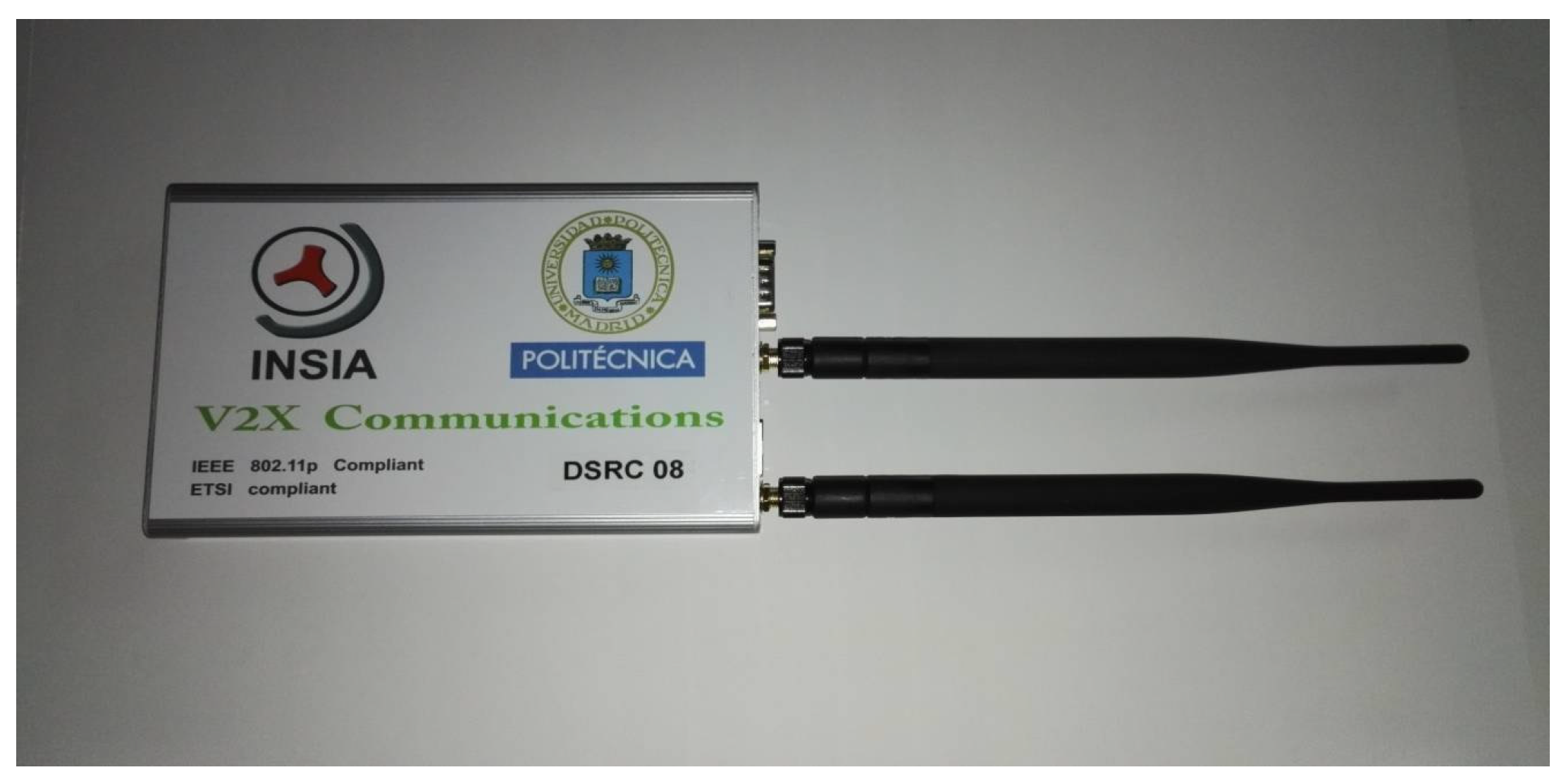
Figure 2.
Open System Interconnection (OSI) model of Geonetworking protocol. MAC: Medium Access Control.
Figure 2.
Open System Interconnection (OSI) model of Geonetworking protocol. MAC: Medium Access Control.

Figure 3.
Software diagram. GeoUnicast (GUC), GeoBroadcast (GBC), Topology Scope Broadcast (TSB), or Location Service (LS).
Figure 3.
Software diagram. GeoUnicast (GUC), GeoBroadcast (GBC), Topology Scope Broadcast (TSB), or Location Service (LS).
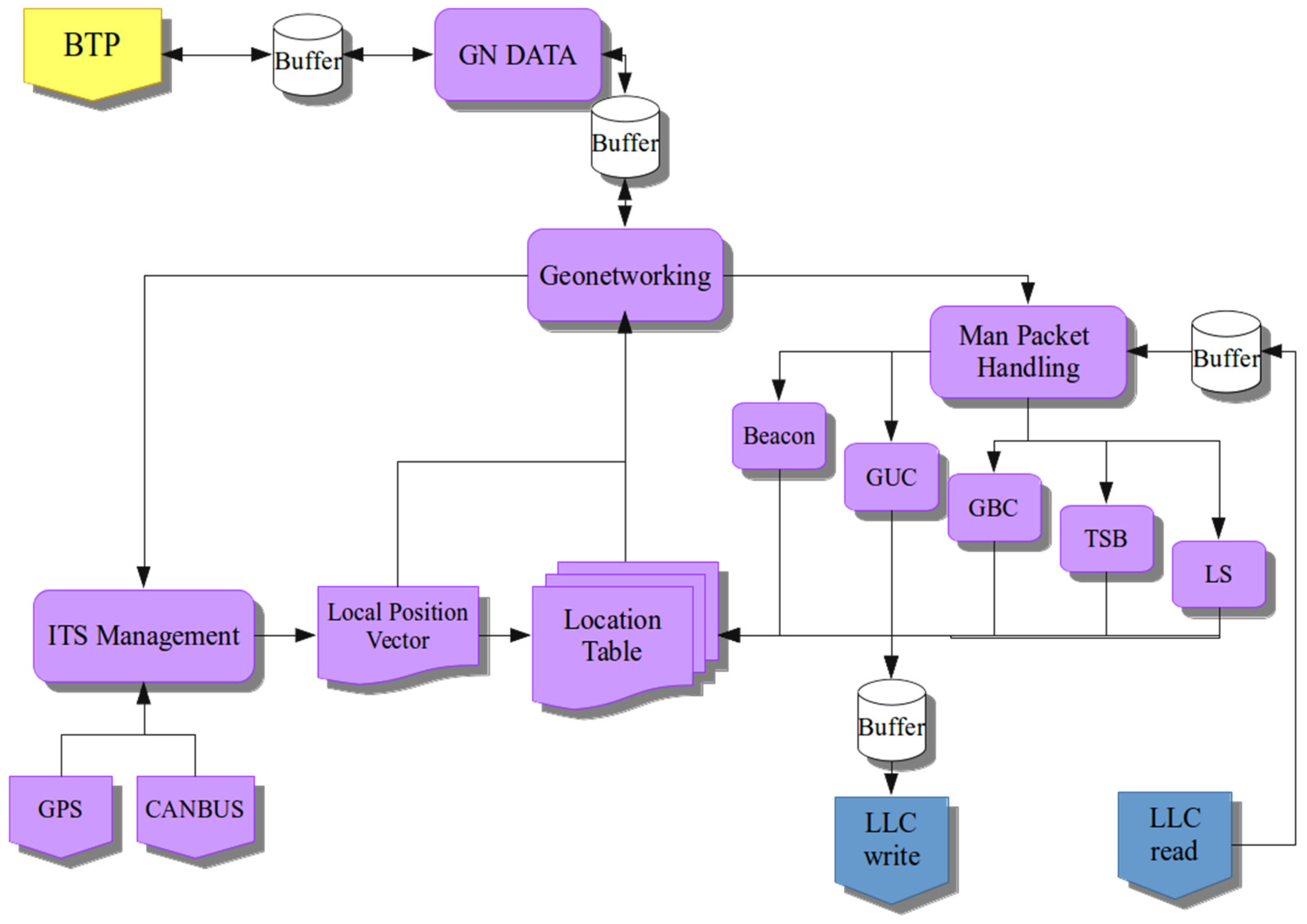
Figure 4.
Bend of the winding road where the Roadside Unit (RSU) was placed.

Figure 5.
Results of Test 1 without RSU.

Figure 6.
Results of Test 2 without RSU.

Figure 7.
Results of Test 3 without RSU.

Figure 8.
Results of Test 4 without RSU.
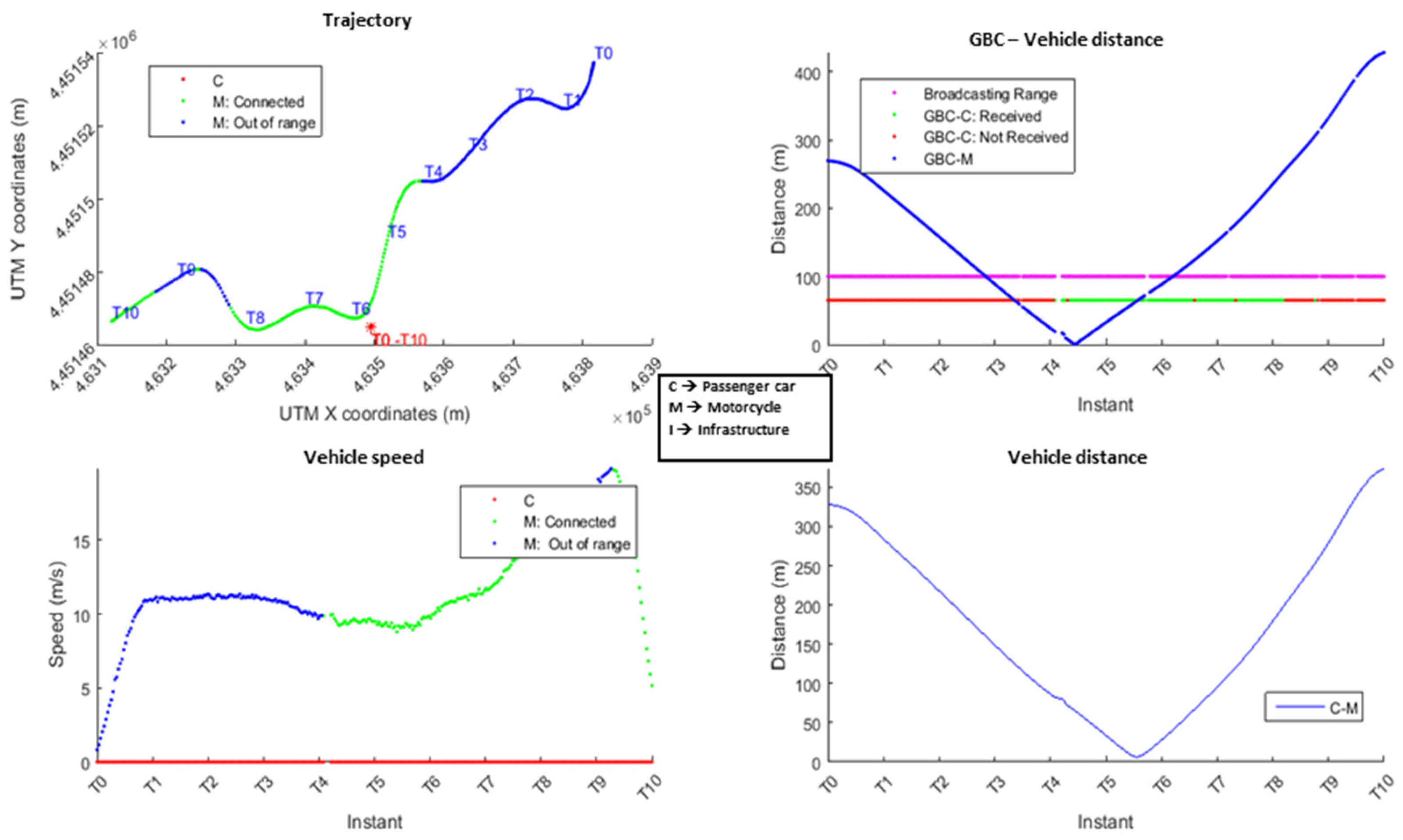
Figure 9.
Results of Test 1 with RSU.

Figure 10.
Results of Test 2 with RSU.

Figure 11.
Results of Test 3 with RSU.
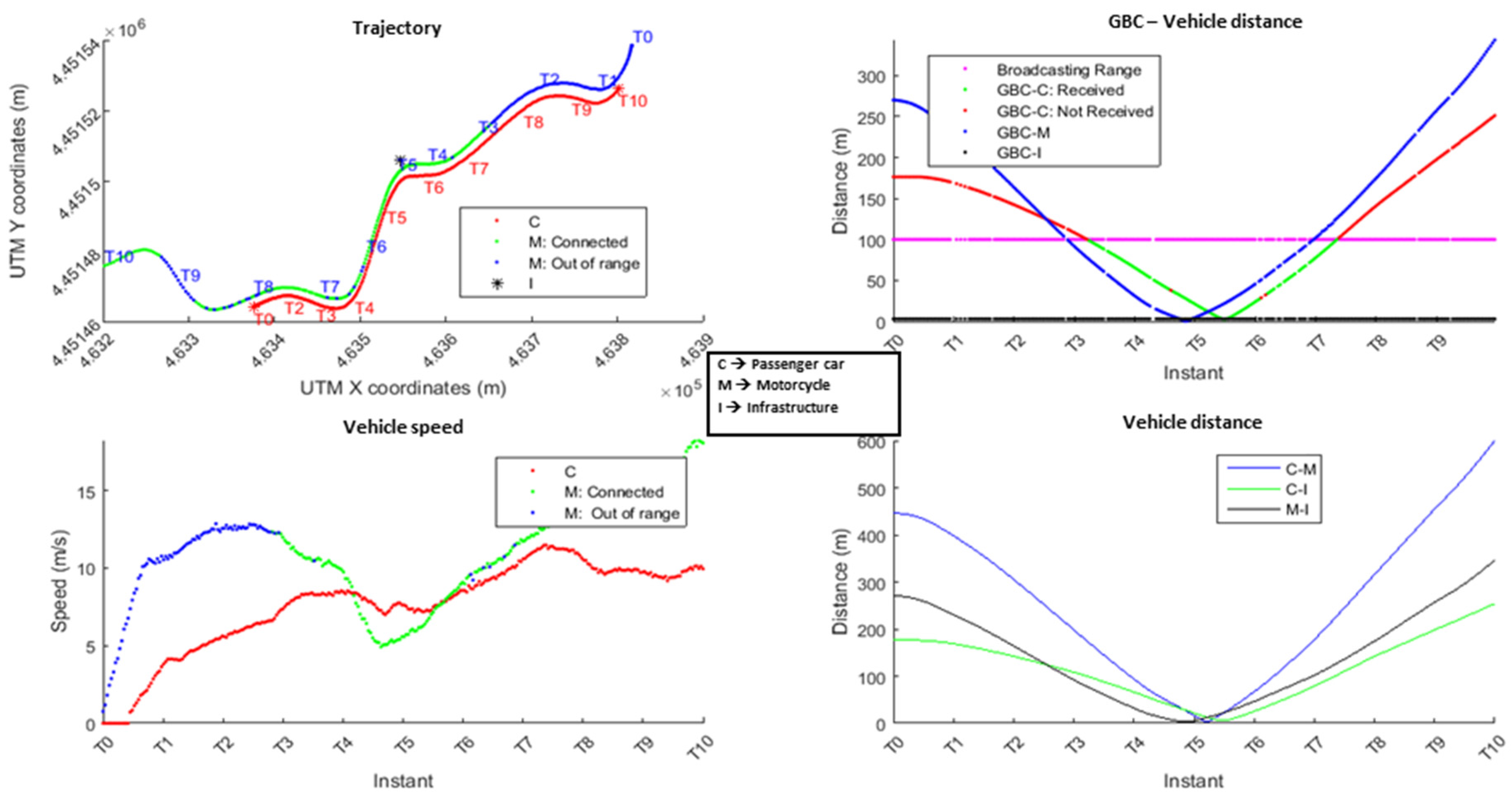
Figure 12.
Results of Test 4 with RSU.


Table 1.
Distribution experiments.
| Vehicle | GBC Characteristics | RSU | |
|---|---|---|---|
| Test 1A | Stopped | Over the motorcycle | NO |
| Test 1B | Stopped | Over the motorcycle | YES |
| Test 2A | Moving | Over the motorcycle | NO |
| Test 2B | Moving | Over the motorcycle | YES |
| Test 3A | Stopped | Over the vertex of the curve | NO |
| Test 3B | Stopped | Over the vertex of the curve | YES |
| Test 4A | Moving | Over the vertex of the curve | NO |
| Test 4B | Moving | Over the vertex of the curve | YES |
Table 2.
Comparison among the different ranges of the system in the tests.
| Distance (Meters) | RSU | Transmission Delay | |
|---|---|---|---|
| Test 1A | 80 m | No | <1 ms |
| Test 1B | 150 m | Yes | <1 ms |
| Test 2A | 60 m | No | <1 ms |
| Test 2B | 150 m | Yes | <1 ms |
| Test 3A | 74 m | No | <1 ms |
| Test 3B | 190 m | Yes | <1 ms |
| Test 4A | 70 m | No | <1 ms |
| Test 4B | 210 m | Yes | <1 ms |
Table 3.
Packets sent and received in the experiments.
| GBC Packets Sent | GBC Packets Sent When the Car Is Inside the Transmission Area | GBC Packets Received by the Car | GBC Packets Not Received Rate | Time Connected | |
|---|---|---|---|---|---|
| Test 1A | 247 | 87 | 65 | 25.3% | 29.8 s |
| Test 1B | 301 | 100 | 88 | 12% | 43 s |
| Test 2A | 179 | 59 | 43 | 27.1% | 15.6 s |
| Test 2B | 224 | 61 | 53 | 13.1% | 29.4 s |
| Test 3A | 308 | 308 | 124 | 59.7% | 36 s |
| Test 3B | 365 | 365 | 253 | 30.6% | 56.2 s |
| Test 4A | 246 | 127 | 61 | 51.9% | 22.4 s |
| Test 4B | 272 | 113 | 109 | 4.4% | 34.6 s |
© 2018 by the authors. Licensee MDPI, Basel, Switzerland. This article is an open access article distributed under the terms and conditions of the Creative Commons Attribution (CC BY) license (http://creativecommons.org/licenses/by/4.0/).
Share and Cite
MDPI and ACS Style
Talavera, E.; Anaya, J.J.; Gómez, O.; Jiménez, F.; Naranjo, J.E. Performance Comparison of Geobroadcast Strategies for Winding Roads. Electronics 2018, 7, 32. https://doi.org/10.3390/electronics7030032
AMA Style
Talavera E, Anaya JJ, Gómez O, Jiménez F, Naranjo JE. Performance Comparison of Geobroadcast Strategies for Winding Roads. Electronics. 2018; 7(3):32. https://doi.org/10.3390/electronics7030032
Chicago/Turabian StyleTalavera, Edgar, José J. Anaya, Oscar Gómez, Felipe Jiménez, and José E. Naranjo. 2018. "Performance Comparison of Geobroadcast Strategies for Winding Roads" Electronics 7, no. 3: 32. https://doi.org/10.3390/electronics7030032
Note that from the first issue of 2016, this journal uses article numbers instead of page numbers. See further details here.