Practical Energy Harvesting for Batteryless Ambient Backscatter Sensors

1
School of ECE, Technical University of Crete, 731 00 Chania, Greece
2
Department of Electrical Engineering, Aristotle University of Thessaloniki, 541 24 Thessaloniki, Greece
3
Department of Physics, Aristotle University of Thessaloniki, Greece and Department of Engineering, University of Nicosia, Nicosia 2417, Cyrpus
*
Author to whom correspondence should be addressed.
Electronics 2018, 7(6), 95; https://doi.org/10.3390/electronics7060095
Submission received: 31 May 2018
/
Revised: 8 June 2018
/
Accepted: 11 June 2018
/
Published: 13 June 2018
(This article belongs to the Special Issue RFID, WPT and Energy Harvesting)
Abstract
:This work studies the performance of two methods for providing power to an ultra-low power, ambient backscatter tag, omitting the need for any battery. RF energy harvesting from a dedicated source and energy harvesting from ambient light using a single photodiode are compared. Extensive measurement results from tests conducted under real world conditions are offered for both harvesting methods. It is concluded that for a total cost of under 7 Euros the need for a battery can be eliminated, by using a single photodiode element along with a suitable boost converter. The ultra-low power character of the utilized tag enables the use of multiple harvesting methods and paves the way towards truly battery-less wireless sensor systems.
1. Introduction
Due to the so-called Internet of Things (IoT) revolution, more and more devices and “things” are expected to communicate with each other. Such requirement imposes technical difficulties, including low power consumption. When considering wireless sensor networks (WSNs), which by definition constitute a large portion of the IoT architecture, ultra-low power consumption is of vital importance. Ultra-low power consumption enables energy harvesting from various ambient sources and thus, eliminates the need for a battery. Battery-less operation offers both reduced operational cost (by eliminating the trouble of changing batteries) and positive environmental impact (i.e., less waste associated with dead batteries).
Backscatter radio is a promising solution for the communication aspect of modern WSNs [1]. Utilizing backscatter techniques for achieving communication, requires a RF switch alternating the loads which terminate the sensor’s antenna; illumination of the sensor is also needed from a dedicated ([2,3,4,5]) or a lready-modulated, i.e., ambient (FM [6,7], DTV [8]) RF source. Replacing active components such as power amplifiers, mixers, oscillators and filters with a simple RF switch, offers tremendous reduction in power consumption. Thus, backscatter radio is a key enabler for designing battery-less sensor systems.
This work studies two methods for providing power to the ultra-low power ambient backscatter tag offered in [6], omitting the need for a battery. The sensor communicates towards a commodity FM receiver by remodulating—using backscatter radio principles—the impinged (to its antenna) signal from a FM broadcasting station; the tag design accomodates any capacitive or resistive sensing element. The energy harvesting methods include: (a) energy harvesting from ambient light using a single photodiode element and (b) RF energy harvesting using sensitive rectenna or rectenna grids [9]. Extensive measurement results are given, including operational rate (duty cycle) and cold start times. All measurements were performed under real world indoor and outdoor conditions. It is found that a single photodiode can perform sufficiently.
2. Tag Communication Setup
The utilized ultra-low power tag is presented in [6]. The tag is able to backscatter information, related to the value of a passive sensor, towards any conventional FM receiver (including FM-radio equipped smartphones), without the need for any dedicated illuminator. The ultra-low power character (power consumption in the order of Watt) of the aforementioned tag, enables the use of multiple harvesting methods and paves the way towards truly battery-less wireless sensor systems.
2.1. Tag Operation
As mentioned above, in order for the utilized tag to backscatter its information, no dedicated illuminator is necessary. Instead, illumination from ambient FM radio stations is exploited and using the FM remodulation method, coupled with selection diversity [6], information related to the value of a passive sensor (either capacitive or resistive) can be received by any conventional FM radio receiver.
FM remodulation is achieved when both the incident on the antenna signal and the signal driving the tag’s switch, are FM-modulated. The impinged signal may come from a FM radio station, encapsulating station’s information (i.e., music, RDS). The signal driving the switch is FM-modulated by another signal, encapsulating information related to the sensor’s value.
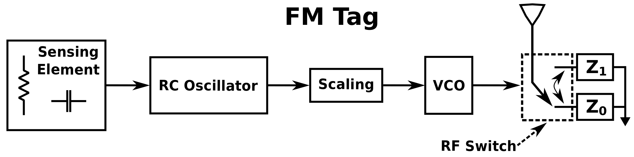
The tag comprises of a sensing element, two oscillators and a RF switch connected to an antenna. The first oscillator is the CSS555, an ultra-low power variant of the 555 timer integrated circuit. It is configured as a RC-oscillator producing a signal with timing characteristics (frequency, duty cycle), depending on the values of the components comprising a RC network. Part of the RC network is a passive sensing element. Thus, the value of the sensing element is translated into frequency via the first oscillator. Additionally, the RC network must be configured such that, regardless of the sensor’s value, the produced signal will have its frequency spectrum within the audio band. The second oscillator is a Silicon Laboratories TS3002 timer, configured to operate as a voltage controlled oscillator (VCO) that drives the RF switch. The input to the VCO is the output of the first oscillator after passing a resistor scaling network (for specific deviation and center frequency values to be attained). That way, the VCO produces a signal that is FM-modulated by the output of the RC oscillator. Thus, the output of the VCO is a FM-modulated signal encapsulating the sensor’s information. The utilized RF switch is an Analog Devices ADG919. A block diagram, depicting the tag’s design, is given in Figure 1.
2.2. Signal Reception
When FM remodulation is achieved, due to backscattering, two new FM signals centered around are created. , are the center frequencies of the illuminating station and the tag’s VCO, respectively. Each of those signals contains information of both the illuminating FM radio station and the tag’s RC oscillator (containing the value of the sensor). It has to be noted that the station’s information signal (e.g., music) acts as interference to the recovery of the tag’s information signal (sensor value).
The nature of the backscattered signals using FM remodulation, allows for any FM demodulation capable receiver, tuned at either of , to recover the RC oscillator’s signal and by extension, the value of the sensing element. The constraint regarding the signal of the RC oscillator to be audible, is imposed such that any conventional FM radio receiver (including those found in (smart) phones) to be able to recover that signal and if possible, extract sensor’s value using frequency estimation techniques (if a smartphone is used for example).
Another aspect of the tag’s design is the fact that its operation is indifferent with respect to the illuminating carrier. A dedicated emitter of unmodulated signals can be also used to illuminate the tag. Under such a scenario, a software defined radio (SDR) in conjunction with a PC may be used. The SDR can be tuned to the appropriate frequency, perform FM demodulation and recover sensor’s value. It must be noted that the tag’s antenna should be tuned to the appropriate frequency. Operating under the illumination from a dedicated emitter, enables the use of RF harvesting to provide power to the tag.
Throughout this work, the tag was tested for correct operation under both ambient (FM radio station) and dedicated/unmodulated illumination. Under the ambient scenario, a Motorola Moto G3 smartphone was used as the receiver. In the dedicated illuminator case, illumination came from the same signals used to provide power via RF harvesting. Correct operation was verified using the FM demodulation function of an Agilent N9912A spectrum analyzer.
3. Power Supply
In this section, the harvesting system implemented for providing power to the tag will be presented. Two energy harvesting cases will be examined, namely harvesting energy from ambient light using a single photodiode and RF energy harvesting using rectennas presented in [9]. The voltage and duty cycle measurements presented in this section were performed using MATLAB and a National Instruments USB-6366 data acquisition system. Duty cycle rate is defined as the percentage of time that the tag is operational.
3.1. Energy Harvesting IC
The operating voltage range of the utilized tag is V to ∼2 V, while the corresponding current consumption range is A to A. Given the fact that the utilized energy harvesting elements can not directly cope with such demands, an energy management/boost converter module is necessary. In this work, the Texas Instruments BQ25504 [10] ultra low power boost converter was utilized. BQ25504 is responsible for managing the power offered by the harvesting element(s), boosting the voltage at the necessary (for tag operation) levels and adjusting the loading of the harvesting element such that maximum power transfer is attained. Additionally, BQ25504 has integrated battery management capabilities; energy storage elements like (super) capacitors and rechargeable batteries can be used in conjunction with the IC. The converter also offers a storage element condition signal (BAT_OK). The latter is asserted when the voltage at the storage element is above a predefined “high” threshold and is de-asserted when the voltage drops below a predefined “low” threshold.
When the storage element is completely discharged (below 100 mV), the boost converter must perform a cold start operation, to charge the storage element up to a specified level ( V). To perform the cold start operation, the input voltage (from the harvesting element) must be at least 330 mV. Once cold start has been completed, the module can manage sources offering voltages ≤330 mV.
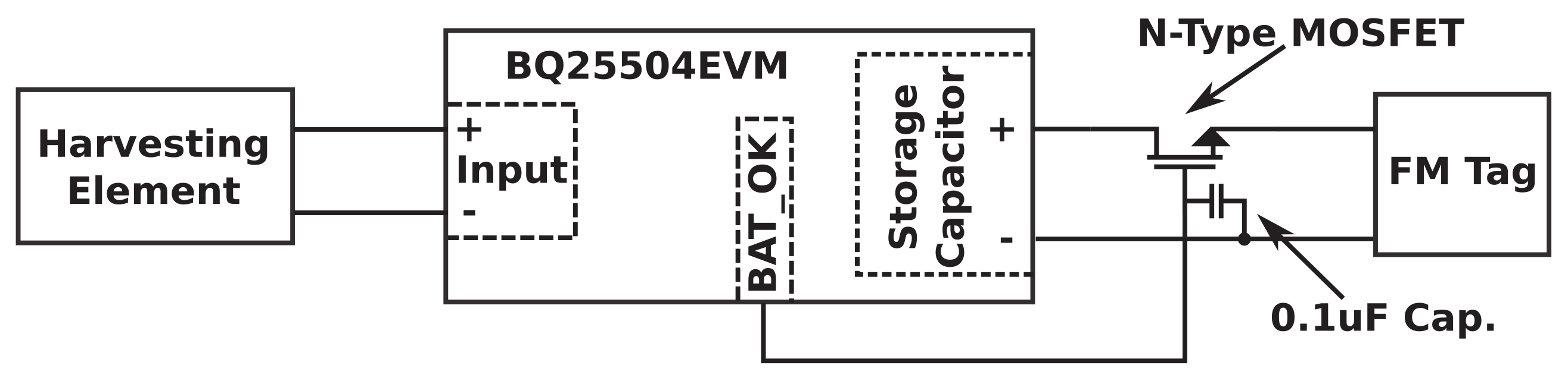
The configuration of the aforementioned module is depicted in Figure 2. In this work, BQ25504 is used in its evaluation board BQ25504EVM. The storage element is a F capacitor and the upper and lower thresholds for the BAT_OK signal are V and V respectively (nominal values). BAT_OK drives a 5LN01SP N-Type MOSFET which in turn connects the FM tag/load into the storage capacitor. Thus, the operating state of the tag (active/inactive) is controlled by the state of BAT_OK signal. A F capacitor was added at the gate of the MOSFET due to oscillations observed in the BAT_OK signal, interfering with correct operation of the tag. At first glance, the use of a single MOSFET to connect the load to the storage element, given the default configuration of the evaluation board, seems a poor design choice. However, the use of a single MOSFET was made on purpose, to exploit the inherent drain-to-source voltage drop of ∼0.8 V such that, even under extreme conditions where the voltage at the storage element would be ∼3 V, the voltage at the tag would settle at ∼2.2 V. Such value, even though outside tag’s safe operating zone, did not affect the correct operation of the tag throughout the tests, both in this work as well as in [6].
The variations of the tag’s supply voltage, can cause a variation in the frequency corresponding to the value of the sensor. For a voltage swing of V to V at the capacitor side, corresponding to a swing of ∼1.6 V to ∼2 V at the tag, the frequency offset was measured in the order of 20 Hz. Depending on the application and the sensing element utilized, the aforementioned offset may not be acceptable. A solution to that problem would be to design the RC network mentioned in Section 2.1, such that the 20 Hz offset would not degrade the measurement accuracy. Another solution would be the utilization of an ultra-low power, low-dropout, voltage regulator.
3.2. Energy Harvesting Using a Single Photodiode
3.2.1. Harvesting Energy from a Photodiode
The first harvesting setup facilitates a photodiode as the element for harvesting energy from ambient light (Figure 3). Examples of designing photodiodes for energy harvesting purposes, can be found in [11,12]. A BPW34 photodiode is used, which is a PIN photodiode; an undoped, intrinsic region of silicon separates the P from the N layers, offering greater quantum efficiency compared to conventional photodiodes and higher response speeds. The aforementioned diode can be seen as a miniature solar cell. To exploit the photodiode as a solar cell, the former is directly connected to the input terminals of the BQ25504EVM setup described in Section 3.1, with its anode connected to the “+” terminal. Under full sunshine conditions, the photodiode was measured to provide an open circuit voltage of V and a short circuit current of mA, while the same figures for an indoor office setup, under fluorescent lighting, were ≈280 mV and ≈5.4 A.
3.2.2. Performance
The performance of the method was tested both in indoor and in outdoor scenarios. In the indoor scenario, under fluorescent lighting inside an office, the system was not able to operate, since the specific photodiode is not matched to the wavelength of the indoor, fluorescent light wavelength. As a result, the utilized boost converter could not perform its cold start operation when the input voltage was below 330 mV and, as mentioned earlier, the photodiode provided only mV. It must be noted that the system would be capable to operate if a different photodiode, sensitive to indoor/fluorescent lighting, was utilized.
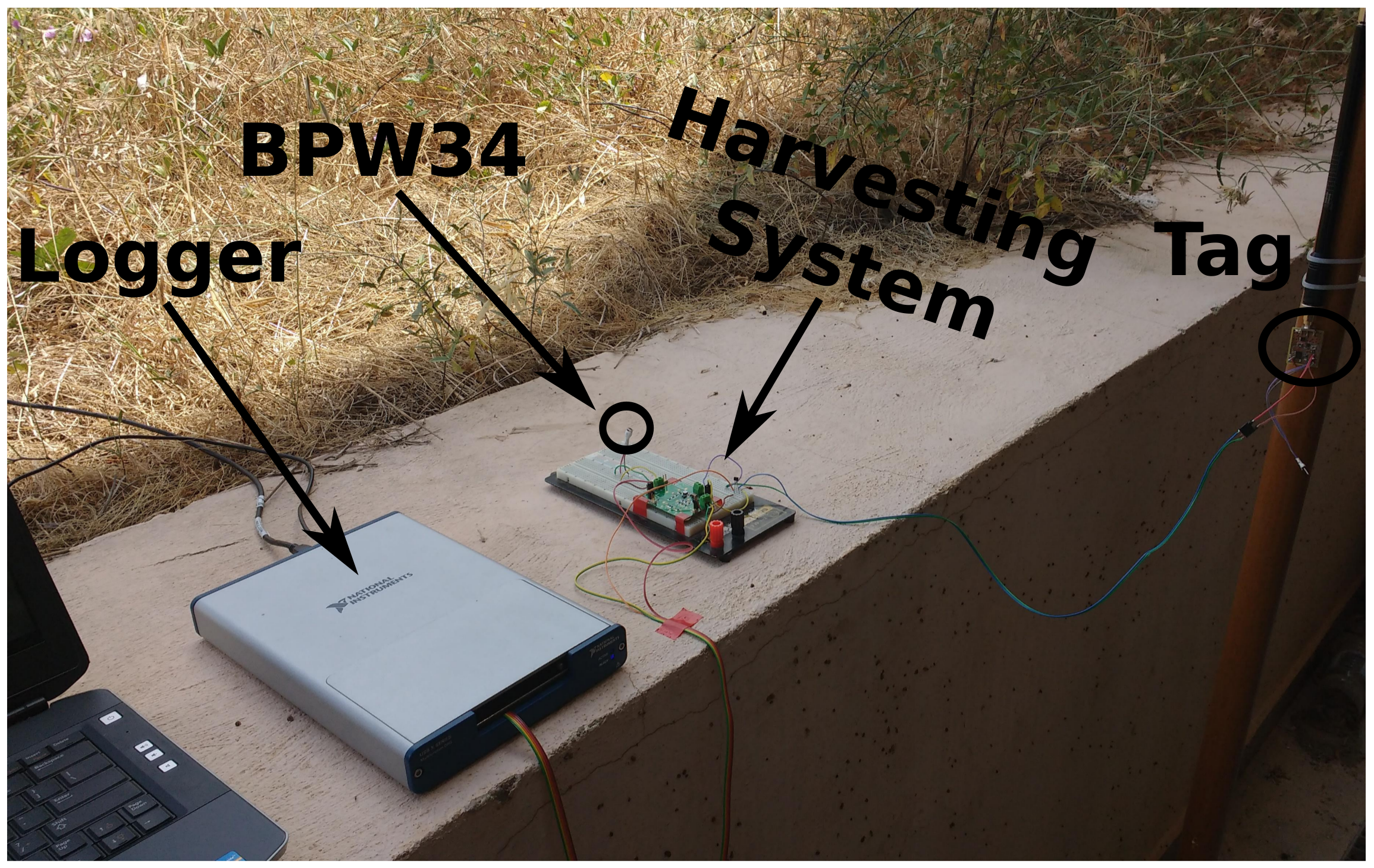
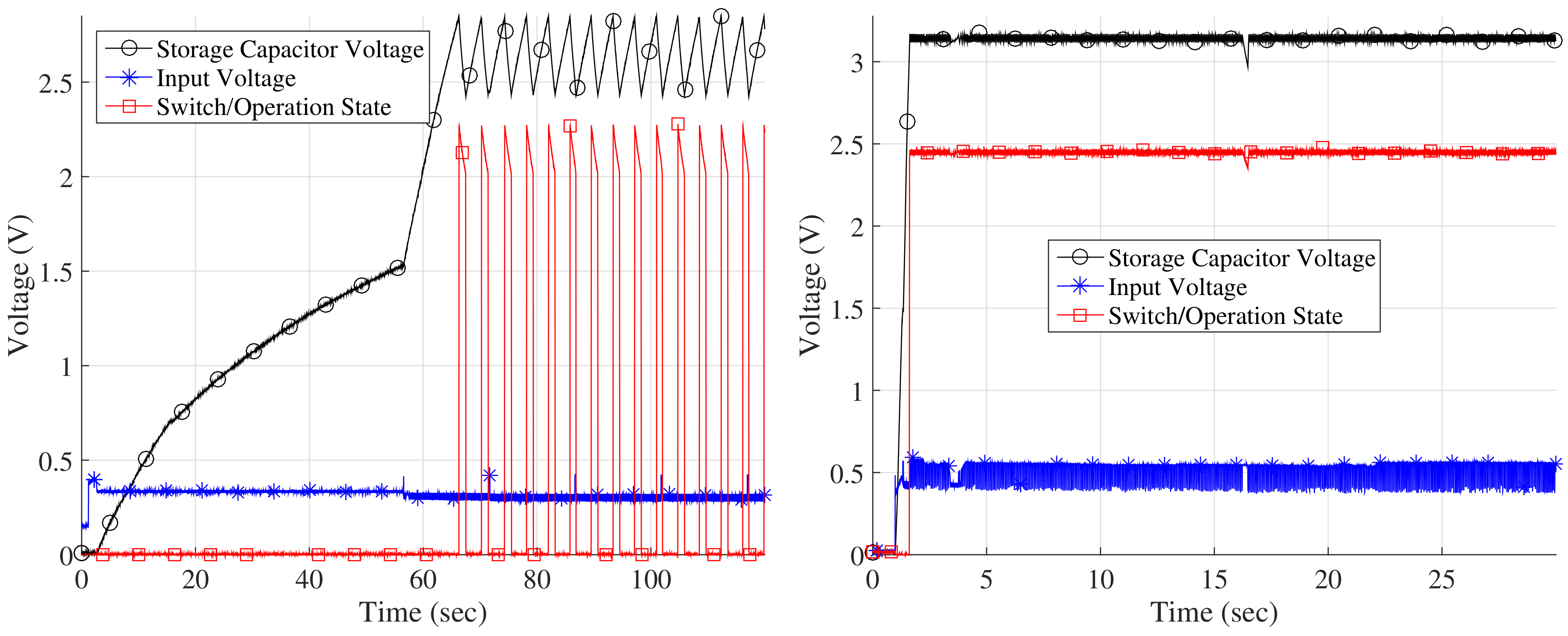
Nevertheless, feasibility of indoor operation was verified: the flashlight of a smartphone was used to provide light to the photodiode. Figure 4 demonstrates the operation under the flashlight scenario. Before every test, the capacitor (storage element) was short circuited in order for it to be completely depleted of charge and for cold start operation to be ensured. It can be observed, that when the smartphone was located 3 cm above the photodiode (Figure 4-Left), approximately one minute is needed for the system to start operation. After the first minute, the system operated in a duty cycled fashion attaining an operational rate of . When the flashlight was placed directly above the photodiode, it can be seen in Figure 4-Right that it needed less than s to begin operation and after that period, attained continuous operation (verified by using the same phone for receiving the backscattered FM remodulated signals).
The system was also tested outdoors, under different illuminating conditions. In Figure 5 and Figure 6, performance under full sunshine and partial sunshine (shadow), respectively, is displayed. It can be seen that under both cases, continuous operation was attained after the cold start procedure which lasted <5 s and <20 s for each case, respectively. In Figure 7 the performance when the photodiode was exposed to limited light, under cloudy conditions, is presented. As it can be seen, after the cold start, duty cycled operation is attained with a rate.
The exact times required for the system to begin operation (when the storage element is completely depleted of charge), under the various lighting conditions described above, are given in Table 1.
3.3. RF Energy Harvesting Using Rectennas
3.3.1. RF Energy Harvesting
To realize energy harvesting from incident RF waves, the rectenna presented in [9], in conjunction with the system described in Section 3.1, was used. The rectenna comprises of a diode-based rectifier directly connected to a bow-tie shaped antenna. Given an input/impinged power of dBm, the rectenna is designed to operate within 842.2–912.1 MHz, while for the same amount of input power, the RF-to-DC conversion efficiency is [9]. Detailed specifications and performance characterization of the utilized RF harvester can be found in [9].
3.3.2. Performance
As with the photodiode performance tests, both outdoor and indoor scenarios were considered. The RF source was a generator configured to produce an unmodulated carrier wave centered at 868 MHz. A 3 dBi monopole antenna was used at the generator.
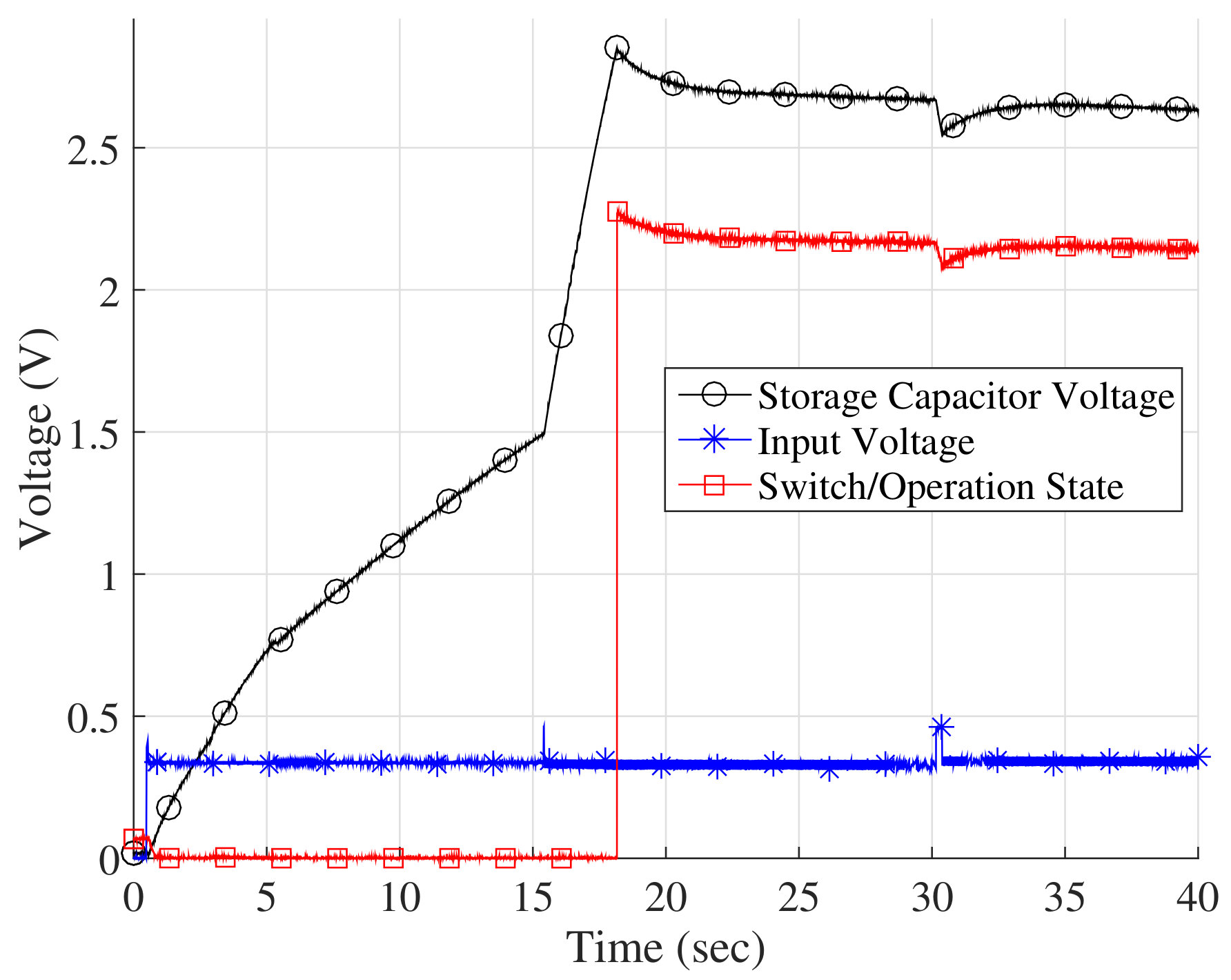
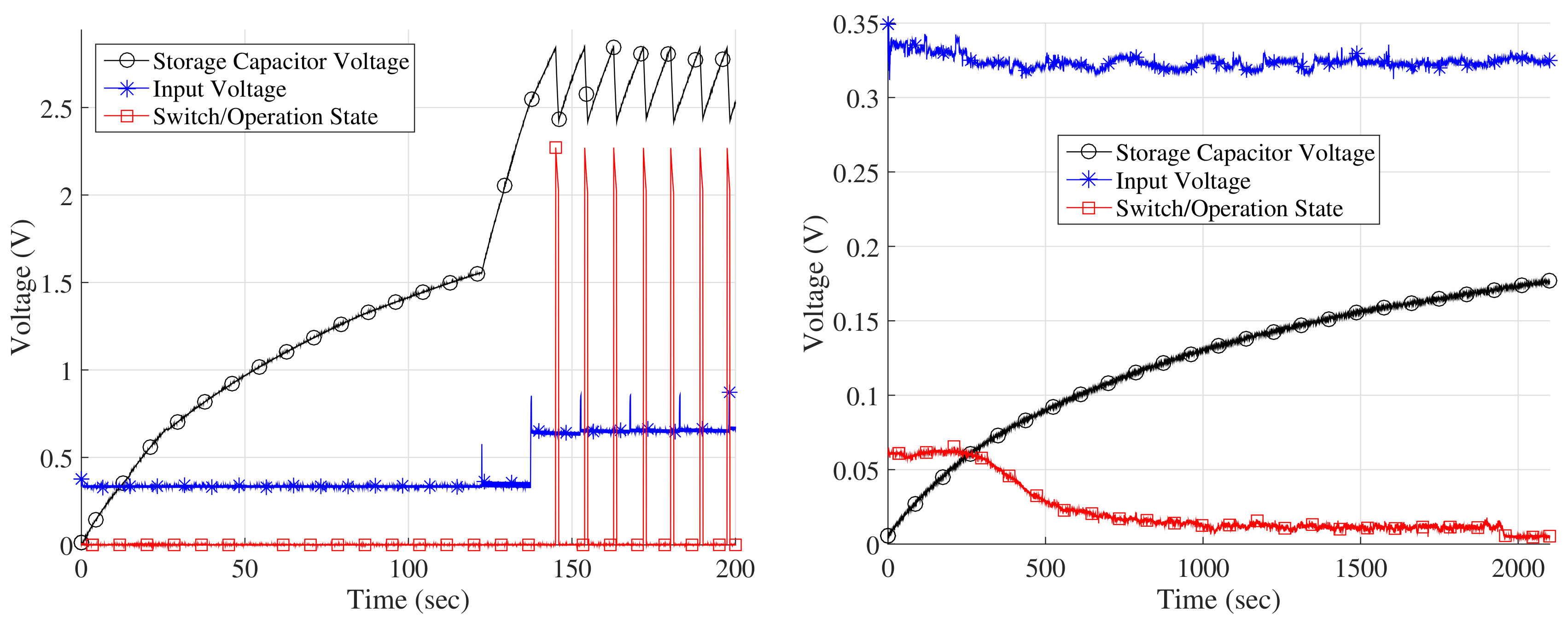
Figure 8 demonstrates the operation of the system, when a single rectenna is used and the generator is configured at 19 dBm. The system with the rectenna was placed m (Figure 8-Left) and m (Figure 8-Right) away from the generator’s antenna. It can be observed that the system fails to start even after 33 minutes, when it is placed m away from the RF source. For 30 dBm configured at the generator, continuous operation was attained after <30 s, m away from the generator while duty cycled operation was attained m away after <100 s. The experimental setup, using a single rectenna can be seen in Figure 9.
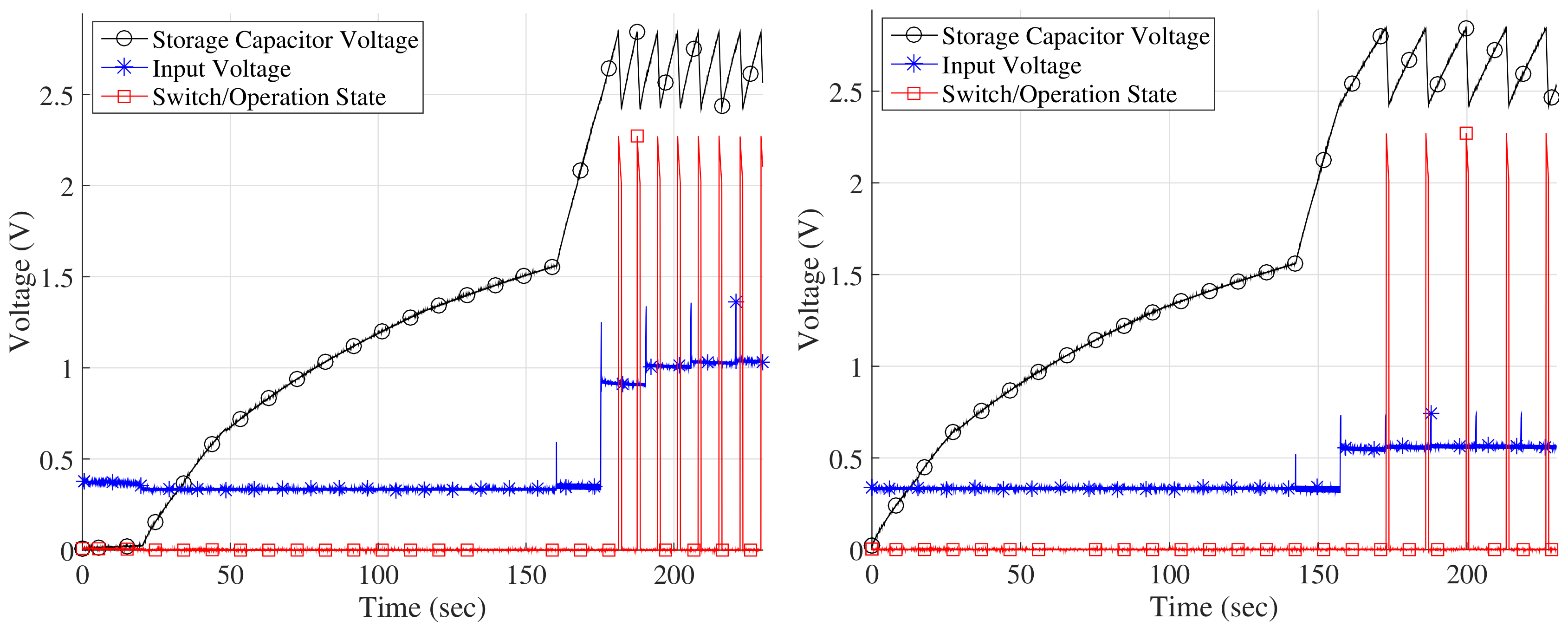
Experiments were also performed using an array (grid) of two rectennas. The rectennas, while being placed cm apart, were connected to the input of the boost converter in either series or parallel configuration. Figure 10 demonstrates the performance of the system when placed m away from the generator, configured at 19 dBm. Figure 10-Left shows the performance when the rectennas are connected in series, while Figure 10-Right the performance when connected in parallel. It can be observed that under series configuration, the system needs more time to begin operation, compared to the respective time under parallel configuration. It can be also observed that the duty cycle rate is higher for the series configuration, compared to the parallel configuration. These observations are explained by the fact that in parallel configuration, more current is potentially available, while in series configuration more voltage is offered. Table 2 offers the exact times required for the system to begin operation (due to cold start phase), when the generator is configured to 19 dBm, under various scenarios. Subsequently, Figure 11 depicts performance considering rectennas connected in parallel, m away from the generator, configured at 30 dBm.
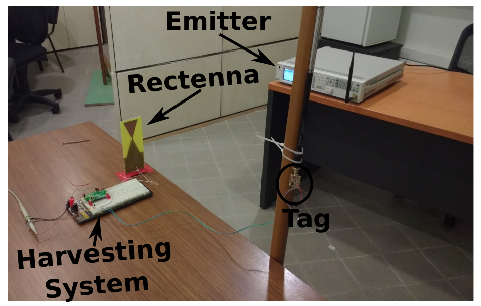
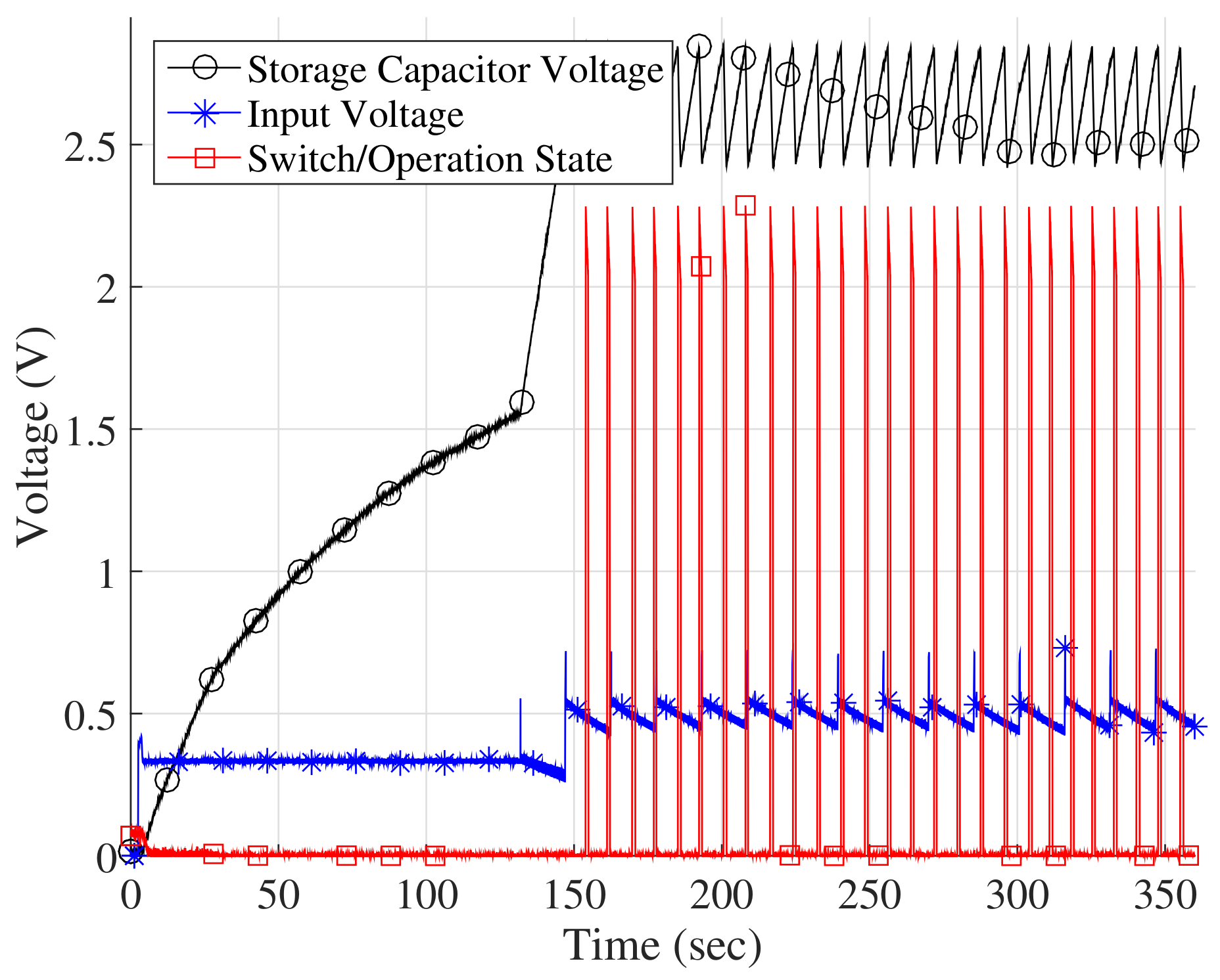
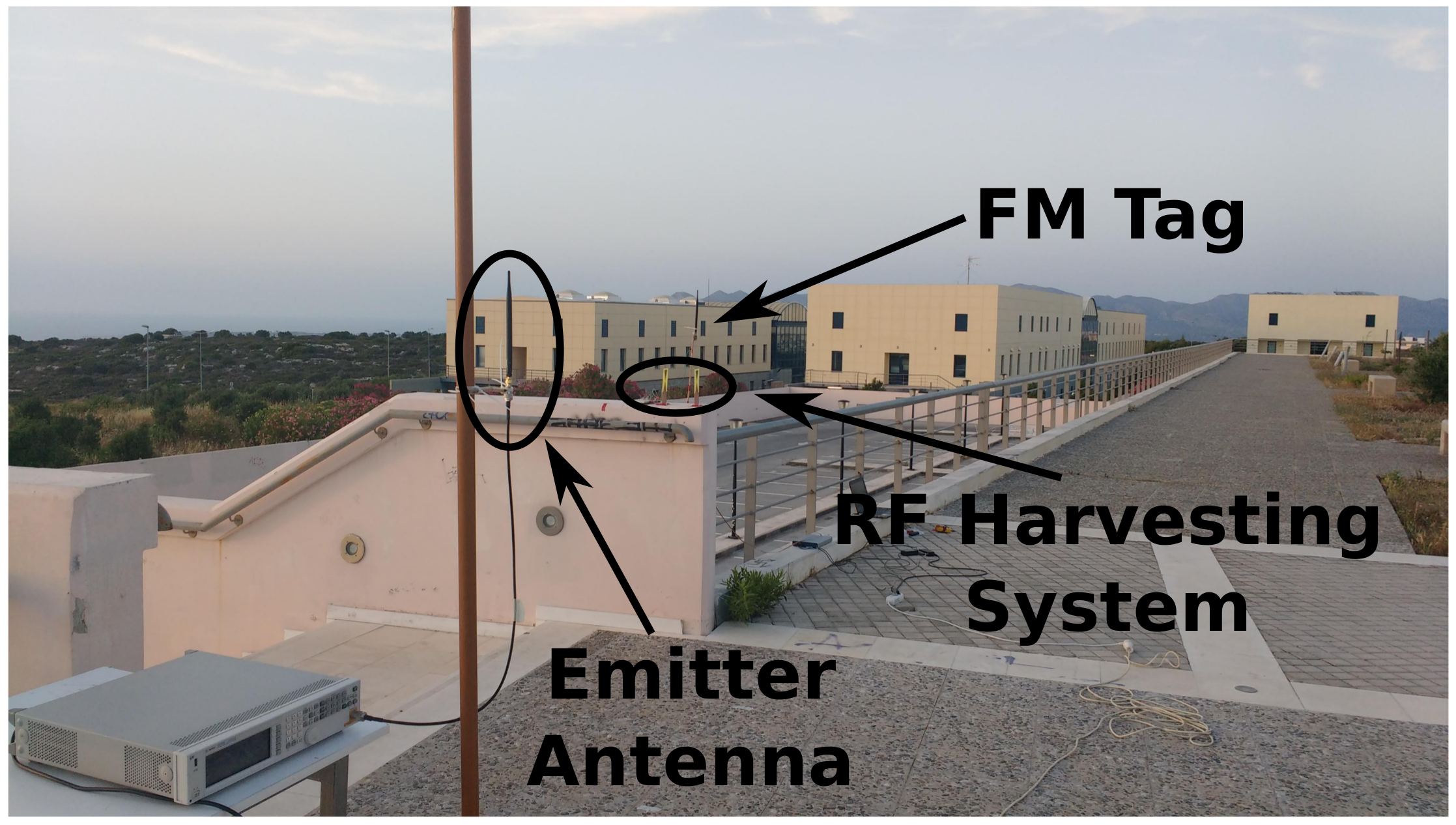
Figure 12 offers the performance for an outdoor scenario and an array of two rectennas (located 3 m away from the RF source) connected in parallel. The generator was configured at 30 dBm. The system was able to operate up to 3 m, displaying poor performance when compared with the indoor tests. That is explained by the fact that the location where the tests were performed contained large metallic objects (as seen in Figure 13). It must be also stated that during the outdoor tests, the tag backscattered at 868 MHz, and correct operation was verified using the FM demodulation function of a spectrum analyzer.
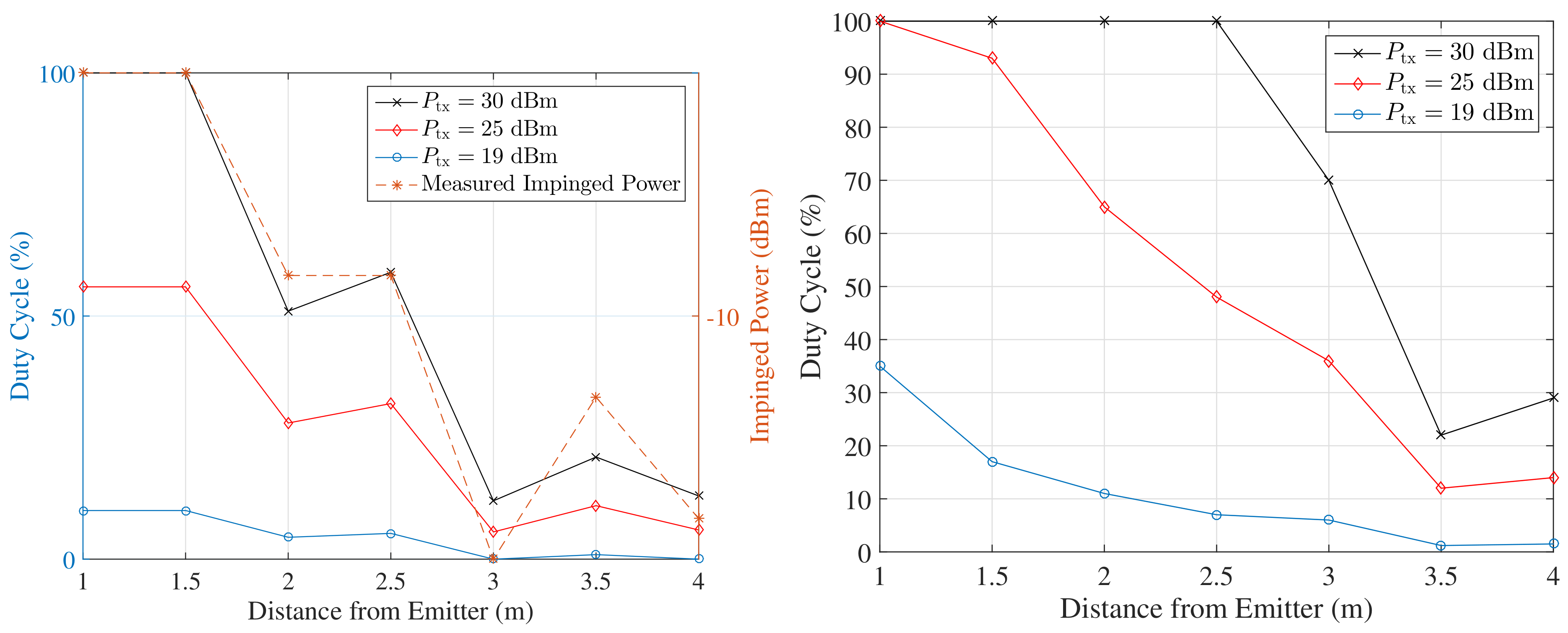
Given that the system has passed the cold start phase, Figure 14 offers the attained duty cycle rate as a function of distance from emitter, for various RF power levels configured at the generator. Figure 14-Left offers the duty cycle rate, when a single rectenna is used. Additionally, Figure 14-Left offers the impinged power at the location of the rectenna, as measured by a spectrum analyzer equipped with an antenna of same (as rectenna’s) design. As expected, the percentage of time the tag operates drops as the distance increases and follows the drop in power. At m, a large desk was present, which might explain the peak in power and duty cycle. The last statement showcases the (inherent) sensitivity of RF harvesting performance, to the location/condition of surrounding environment. Figure 14-Right offers the duty cycle rate when two rectennas are used. An interesting observation is the fact that no peak is evident, as was in Figure 14-Left. That might be explained by the directive characteristics resulting due to array formation caused by the two rectennas.
3.4. Comparison of the Methods
The selection between which of the studied harvesting methods should be utilized depends solely on the application requirements. If a backscatter network is considered, where a dedicated emitter is present and autonomous operation is required, even during the night (absence of light), then RF energy harvesting may offer the solution. When such solution is considered, one must take into account both duty cycle requirements and the fact that tags must be relatively close to the emitter, so that the sensitivity requirements of the RF harvester(s) are satisfied.
When considering a backscatter link, which exploits ambient carriers and its operation is “on demand”, i.e., a person needs to interrogate a sensor using a smartphone, the photodiode solution seems more viable, both in terms of monetary cost and practicality. Even when lighting conditions are not favourable (e.g., indoor lighting), the user can expose the photodiode to the flashlight of a smartphone and power the tag, while at the same time the same smartphone performs sensor interrogation using ambient backscatter.
4. Conclusions
This work presented two methods for powering an ambient backscatter radio sensor tag [6]. It was demonstrated that using either a single photodiode (instead of solar panel of considerable size and cost) or RF harvesting rectennas, in combination with a boost converter, can provide power to the tag and offer either continuous or duty cycled operation, depending on the conditions. It was shown that the tag can operate without the need for a battery, at the cost of the boost converter, peripherals and the harvesting element. Utilization of RF harvesting, in the context of the studied setup, results to performance heavily dependent on the condition of the surrounding space, while requiring a dedicated emitter. On the other hand, it was demonstrated that energy harvesting from a single photodiode is a practical and cost-effective solution. Batteryless operation of the wireless ambient tag/sensor under sunny, partly cloudy or cloudy conditions was demonstrated. Operation during the night with a flashlight is also possible. Future work will focus on photodiodes tailored to indoor, fluorescent wavelength, RF harvesting from ambient signals, as well as multi-modal energy harvesting, i.e., combining multiple different harvesting sources, tailored to the application.
Author Contributions
Conceptualization, A.B.; Data curation, G.V.; Formal analysis, G.V. and J.S.; Funding acquisition, A.B.; Investigation, G.V. and A.D.; Methodology, A.B.; Project administration, J.S.; Supervision, J.S.; Validation, J.S.; Writing–original draft, G.V.; Writing–review & editing, A.D. and A.B.
Funding
This research has been financially supported by General Secretariat for Research and Technology (GSRT) and the Hellenic Foundation for Research and Innovation (HFRI) (Scholarship Code: 2263) and by the “Association of Mobile Telephony Companies, Greece”, Grant Number RC AUTH 93022.
Conflicts of Interest
The authors declare no conflict of interest.
References
- Vannucci, G.; Bletsas, A.; Leigh, D. A software-defined radio system for backscatter sensor networks. IEEE Trans. Wirel. Commun. 2008, 7, 2170–2179. [Google Scholar] [CrossRef]
- Kampianakis, E.; Kimionis, J.; Tountas, K.; Bletsas, A. A remotely programmable modular testbed for backscatter sensor network research. In Real-World Wireless Sensor Networks: Proceedings of the 5th International Workshop; Springer: Cham, Switzerland, 2014; pp. 153–161. [Google Scholar]
- Kampianakis, E.; Kimionis, J.; Tountas, K.; Konstantopoulos, C.; Koutroulis, E.; Bletsas, A. Wireless environmental sensor networking with analog scatter radio timer principles. IEEE Sens. J. 2014, 14, 3365–3376. [Google Scholar] [CrossRef]
- Fasarakis-Hilliard, N.; Alevizos, P.N.; Bletsas, A. Coherent detection and channel coding for bistatic scatter radio sensor networking. IEEE Trans. Commun. 2015, 63, 1798–1810. [Google Scholar] [CrossRef]
- Vougioukas, G.; Daskalakis, S.N.; Bletsas, A. Could battery-less scatter radio tags achieve 270-meter range? In Proceedings of the IEEE Wireless Power Transfer Conference (WPTC), Aveiro, Portugal, 5–6 May 2016; pp. 1–3. [Google Scholar]
- Vougioukas, G.; Bletsas, A. 24 μW 26 m range batteryless backscatter sensors with FM remodulation and selection diversity. In Proceedings of the IEEE International Conference on RFID Technology Application (RFID-TA), Warsaw, Poland, 20–22 September 2017. [Google Scholar]
- Wang, A.; Iyer, V.; Talla, V.; Smith, J.R.; Gollakota, S. FM backscatter: Enabling connected cities and smart fabrics. In Proceedings of the 14th USENIX Symposium on Networked Systems Design and Implementation, Boston, MA, USA, 27–29 March 2017. [Google Scholar]
- Liu, V.; Parks, A.; Talla, V.; Gollakota, S.; Wetherall, D.; Smith, J.R. Ambient backscatter: Wireless communication out of thin air. In Proceedings of the ACM SIGCOMM 2013 Conference on SIGCOMM, Hong Kong, China, 12–16 August 2013; pp. 39–50. [Google Scholar]
- Assimonis, S.D.; Daskalakis, S.-N.; Bletsas, A. Sensitive and efficient RF harvesting supply for batteryless backscatter sensor networks. IEEE Trans. Microw. Theory Tech. 2016, 64, 1327–1338. [Google Scholar] [CrossRef]
- Texas Instruments Inc. bq25504 Ultra Low-Power Boost Converter With Battery Management for Energy Harvester Applications. Available online: http://www.ti.com/lit/ds/symlink/bq25504.pdf (accessed on 28 February 2018).
- Guilar, N.J.; Kleeburg, T.J.; Chen, A.; Yankelevich, D.R.; Amirtharajah, R. Integrated solar energy harvesting and storage. IEEE Trans. VLSI Syst. 2009, 17, 627–637. [Google Scholar] [CrossRef]
- Fong, E.G.; Guilar, N.J.; Kleeburg, T.J.; Pham, H.; Yankelevich, D.R.; Amirtharajah, R. Integrated energy-harvesting photodiodes with diffractive storage capacitance. IEEE Trans. VLSI Syst. 2013, 21, 486–497. [Google Scholar] [CrossRef]
Figure 1.
Block diagram of the utilized FM tag [6].
Figure 1.
Block diagram of the utilized FM tag [6].

Figure 2.
Harvesting system block diagram.

Figure 3.
Setup for performance measurements of powering the tag using a single photodiode (partial sunshine condition).
Figure 3.
Setup for performance measurements of powering the tag using a single photodiode (partial sunshine condition).

Figure 4.
Cold start of the photodiode-based harvesting system when illuminated by the flashlight of a smartphone (indoors). (Left) Smartphone was 3 cm above the photodiode (attaining duty cycled operation at a rate ), (Right) smartphone was directly above the photodiode. The Switch/Operation State waveform corresponds to the state of the BAT_OK signal and by extension, to the operating state of the tag (active/inactive).

Figure 5.
Cold start of the system using a photodiode as harvesting element under full sunshine conditions.
Figure 5.
Cold start of the system using a photodiode as harvesting element under full sunshine conditions.

Figure 6.
Cold start of the system using a photodiode as harvesting element under shadow/ partial sunshine conditions.
Figure 6.
Cold start of the system using a photodiode as harvesting element under shadow/ partial sunshine conditions.

Figure 7.
Cold start of the system using a photodiode as harvesting element under cloudy conditions. Duty cycled operation at a rate, can be observed.
Figure 7.
Cold start of the system using a photodiode as harvesting element under cloudy conditions. Duty cycled operation at a rate, can be observed.

Figure 8.
Cold start using a single rectenna (Left) m and (Right) m away from emitter (indoors, dBm).
Figure 8.
Cold start using a single rectenna (Left) m and (Right) m away from emitter (indoors, dBm).

Figure 9.
Indoor setup for energy harvesting measurements. A single rectenna can be seen.

Figure 10.
Cold start using two rectennas, m away from emitter, in series (Left) or parallel (Right) configuration (indoors, dBm).
Figure 10.
Cold start using two rectennas, m away from emitter, in series (Left) or parallel (Right) configuration (indoors, dBm).

Figure 11.
Cold start using two rectennas, m away from emitter, in parallel configuration (indoors, dBm).
Figure 11.
Cold start using two rectennas, m away from emitter, in parallel configuration (indoors, dBm).

Figure 12.
Cold start using two rectennas 3 m away from emitter in an outdoor setup (rectennas in parallel, dBm).
Figure 12.
Cold start using two rectennas 3 m away from emitter in an outdoor setup (rectennas in parallel, dBm).

Figure 13.
Outdoor setup for energy harvesting measurements. Two rectennas in a parallel configuration were used.
Figure 13.
Outdoor setup for energy harvesting measurements. Two rectennas in a parallel configuration were used.

Figure 14.
(Left) Duty cycle vs distance from carrier emitter for the case of a single rectenna. The impinged power is also displayed (generator configured at 25 dBm). (Right) Duty cycle for the case of two rectennas in a parallel configuration.
Figure 14.
(Left) Duty cycle vs distance from carrier emitter for the case of a single rectenna. The impinged power is also displayed (generator configured at 25 dBm). (Right) Duty cycle for the case of two rectennas in a parallel configuration.

Figure 15.
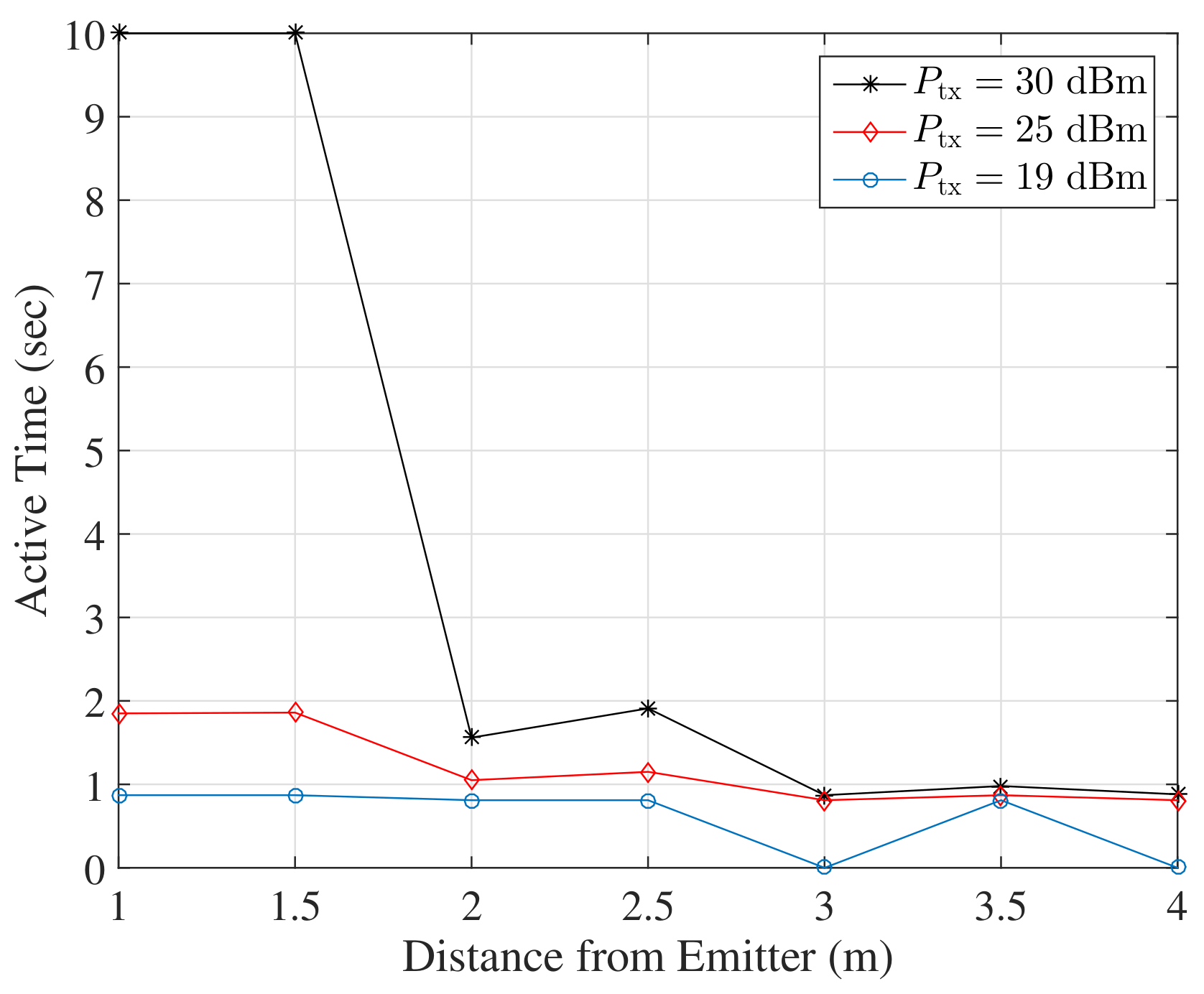
Active (operating) time vs distance from carrier emitter for the case of a single rectenna (10 s translates to continuous operation).
Figure 15.
Active (operating) time vs distance from carrier emitter for the case of a single rectenna (10 s translates to continuous operation).

Figure 16.
Active time for the case of two rectennas in a parallel configuration. A value of 10 s translates to continuous operation.
Figure 16.
Active time for the case of two rectennas in a parallel configuration. A value of 10 s translates to continuous operation.


Table 1.
Time required for cold start of the system, using a photodiode as the harvesting element.
| Lighting Condition | Full Sunshine | Partial Sunshine | Cloudy | Phone (3 cm) | Phone (direc.) |
|---|---|---|---|---|---|
| Cold Start Duration (s) |
Table 2.
Time required for cold start of the system using RF harvesting. The generator was configured at 19 dBm.
Table 2.
Time required for cold start of the system using RF harvesting. The generator was configured at 19 dBm.
| Distance from RF Source (m) | 1.5 | 2.5 |
|---|---|---|
| Single Rectenna | 145 s | FAIL |
| Two Rectennas in Series | s | s |
| Two Rectennas in Parallel | s | s |
© 2018 by the authors. Licensee MDPI, Basel, Switzerland. This article is an open access article distributed under the terms and conditions of the Creative Commons Attribution (CC BY) license (http://creativecommons.org/licenses/by/4.0/).
Share and Cite
MDPI and ACS Style
Vougioukas, G.; Dimitriou, A.; Bletsas, A.; Sahalos, J. Practical Energy Harvesting for Batteryless Ambient Backscatter Sensors. Electronics 2018, 7, 95. https://doi.org/10.3390/electronics7060095
AMA Style
Vougioukas G, Dimitriou A, Bletsas A, Sahalos J. Practical Energy Harvesting for Batteryless Ambient Backscatter Sensors. Electronics. 2018; 7(6):95. https://doi.org/10.3390/electronics7060095
Chicago/Turabian StyleVougioukas, Georgios, Antonis Dimitriou, Aggelos Bletsas, and John Sahalos. 2018. "Practical Energy Harvesting for Batteryless Ambient Backscatter Sensors" Electronics 7, no. 6: 95. https://doi.org/10.3390/electronics7060095
Note that from the first issue of 2016, this journal uses article numbers instead of page numbers. See further details here.