Article

Accurate Synchronization of Digital and Analog Chaotic Systems by Parameters Re-Identification

1
Department of Computer-Aided Design, Saint-Petersburg Electrotechnical University “LETI”, Saint Petersburg 197376, Russia
2
Youth Research Institute, Saint-Petersburg Electrotechnical University “LETI”, Saint Petersburg 197376, Russia
*
Author to whom correspondence should be addressed.
Electronics 2018, 7(7), 123; https://doi.org/10.3390/electronics7070123
Submission received: 30 June 2018 / Revised: 14 July 2018 / Accepted: 18 July 2018 / Published: 20 July 2018

Abstract

:
The verification of the digital models of chaotic systems and processes is a valuable problem in many practical applications, such as nonlinear control and communications. In our study, we propose a hybrid technique for chaotic systems’ identification, based on the chaotic synchronization of digital and analog counterparts and a numerical optimization method used for the fine tuning of parameters. An analog circuit implementing the Rössler oscillator with digitally controlled parameters was chosen as an identification object, and the FPGA model was used as a digital counterpart for coupling and parameter retrieval. The synchronization between analog and digital chaotic models can be used to estimate the quality of an identification procedure. The results of this study clarify the practical bounds of digital and analog systems’ equivalence. They also contribute to the problem of designing technical systems possessing advantages of both analog and digital chaotic generators (e.g., a high accuracy and protection from quasi-chaotic oscillation modes).

1. Introduction

Nowadays, chaos is common in a number of applications, including chaotic communicational systems [1], chaotic encryption systems [2], chaotic sensors [3], and others. The major advantages of chaotic oscillators over traditional harmonic and stochastic signal generators are that they provide a simple way to obtain unique patterns resistive to the crosstalk effect, and they possess the possibility to synchronize with each other, which is a convenient mechanism to observe and control the state of a chaotic system. Digital chaotic oscillators also provide fully repeatable broadband signals. However, the great influence of the numerical method used for discretization makes them unsuitable for some applications [4].
Today, strong evidence exists that the numerical simulation of chaotic systems meets notable difficulties. Round-off errors existing in both fixed and floating point arithmetic [5] and truncation errors, rising from discrete operator application [6] may violate simulation results in a crucial way. Even an order of arithmetical operations makes sense in a chaotic system simulation, and mathematically equivalent but arithmetically different numerical schemes may sufficiently differ in their properties [7].
Chaotic behavior appears in a variety of analog systems, including circuits with memristive elements [8,9], elements with hysteresis [10], and other nonlinear devices [11] (e.g., ones with exponential nonlinearity [12]), as well as in analog artificial neural networks, chaotic sensing, and transmitting systems. The analog electrical oscillators demonstrate ‘real’ chaos, representing dynamics close to continuous mathematical models. This motivated some researchers to construct hybrid analog–digital systems based on an analog chaotic generator, with digital inputs and outputs for practical applications [13]. However, this approach appears to be redundant if a proper digital model is found, verified, and implemented as a digital embedded system.
In a previous work, a practical possibility for the synchronization between analog and digital chaotic systems was shown experimentally [14]. This result leads to an idea that one of the possible ways to verify digital chaotic models is the synchronization between these models and their continuous counterparts. A low synchronization error would show the relevance of the digital model. With the use of modern circuitry and data acquisition instruments, a simple setup can be built to make an experimental study of analog and digital systems’ equivalence.
In this paper, we contribute to the problem of constructing reliable chaotic system simulators, proposing a complex approach based on a hybrid analog–digital synchronization concept with parameter re-identification. This research studies the performance of a hybrid analog–digital coupled system in which a continuous circuit controls the dynamics of the digital one. Our concept is aimed at reducing synchronization error as much as possible. This requires precise parametric identification using an optimization technique, as the imperfectness of analog elements making up an experimental circuit, as well as errors in multipliers and operational amplifiers, introduce notable deviations from the intended design.
In our study, we investigate the Rössler chaotic system as an illustrative example, because of its simplicity and the possibility of the parametric identification of this system via optimization, as previously shown [15]. In a future work, more complicated systems are intended to be tested (e.g., based on nonlinear autoregressive moving average models with exogenous inputs [16]).
The paper is organized as follows. Firstly, we describe the chaotic system parameters’ identification technique based on optimization schemes and a comparison of bifurcation diagrams. Secondly, we briefly define the semi-implicit symplectic numerical method and its application for FPGA chaotic generator implementation. Finally, we show that the analog–digital synchronization shows better accuracy compared to the analog circuits synchronization, which demonstrates the sufficiency of the provided concept.

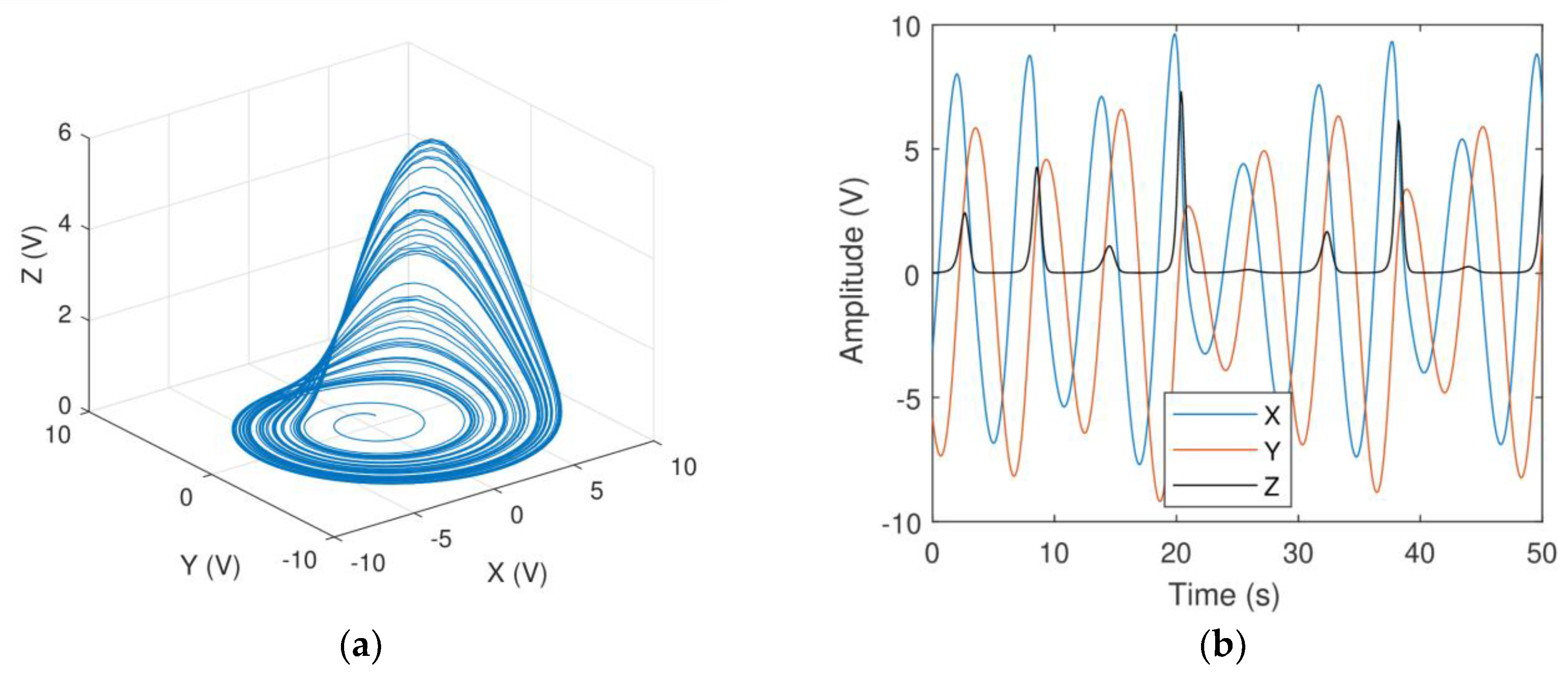
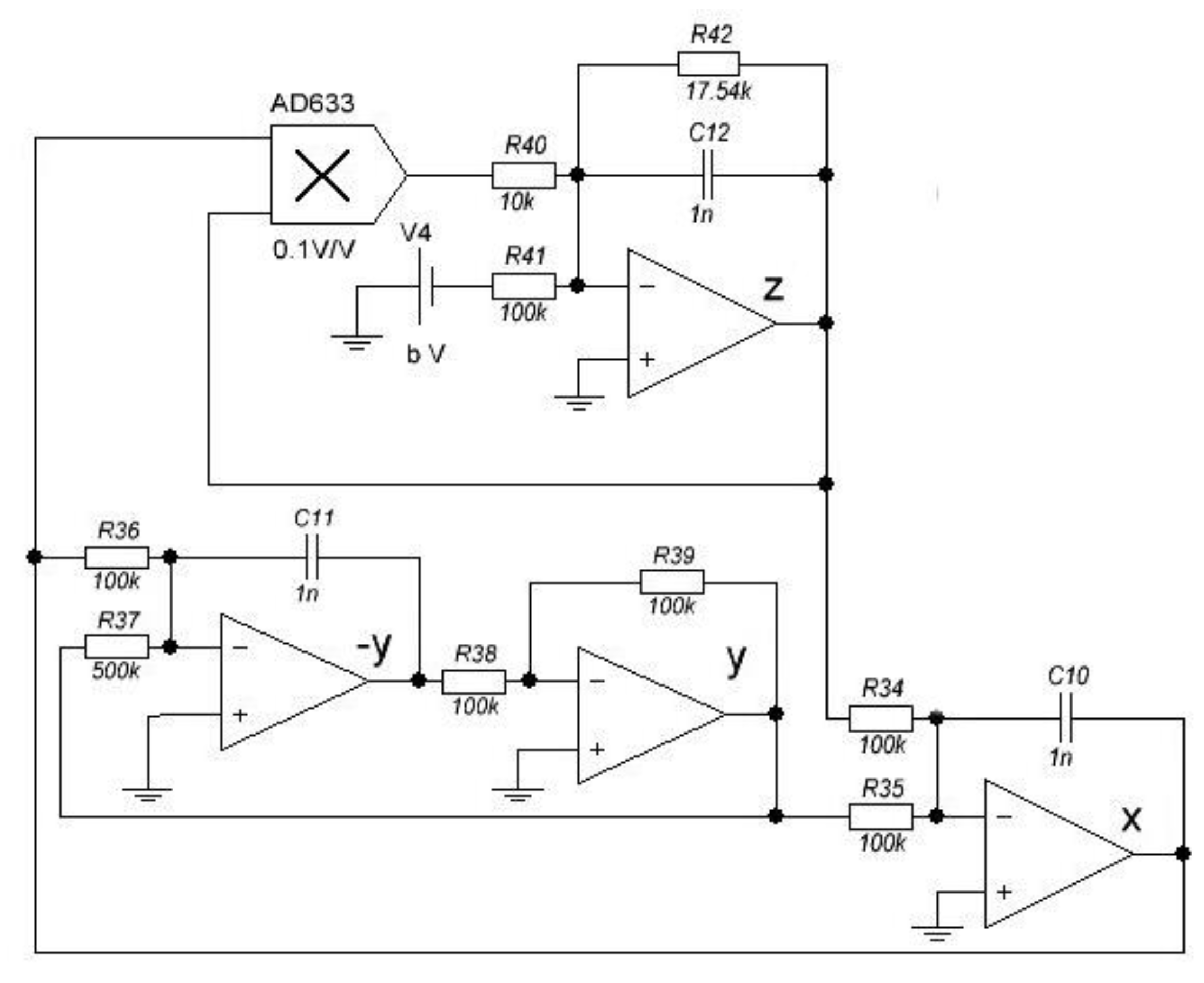
2. Materials and Methods: Identification of Rössler Oscillator Analog Model

An adapted version of the Rössler chaotic system [17] is determined by the differential equation, as follows:
x ˙ = y d z y ˙ = x + a y z ˙ = b + z ( x c )  
This system has four parameters, a , b , c , d . We have introduced parameter d, which was not included in the original Rössler equation, to keep the amplitude of the state variables within an interval of [ 10 ; 10 ] volts required by the analog-to-digital converter of our digital oscilloscope. With parameters, as follows:
a = 0.2 , b = 0.2 , c = 5 , d = 2  
System (1) shows the system dynamic, presented in Figure 1.
An electronic circuit modeling of System (1) is presented in Figure 2. It consists of RC passive components, precise operational amplifiers (OPA2277 (Texas Instruments, Austin, TX, US)) implementing adding integrators, and an analog multiplier (AD633 (Analog Devices, Norwood, MA, US)). This solution, however, allows for changing only the nonlinear parameter, b . In our study, a more sophisticated analog solution was used, involving digital potentiometers MCP410XX, as presented in Figure A1, see Appendix A. The PCB design is shown in Figure A2, and the images of the circuit are shown in Figure A3.
After recording 3000 samples of analog circuit signal, the following optimization scheme was used:
  • The record was divided into smaller pieces. Sequences of 400, 800, and 1200 points were used.
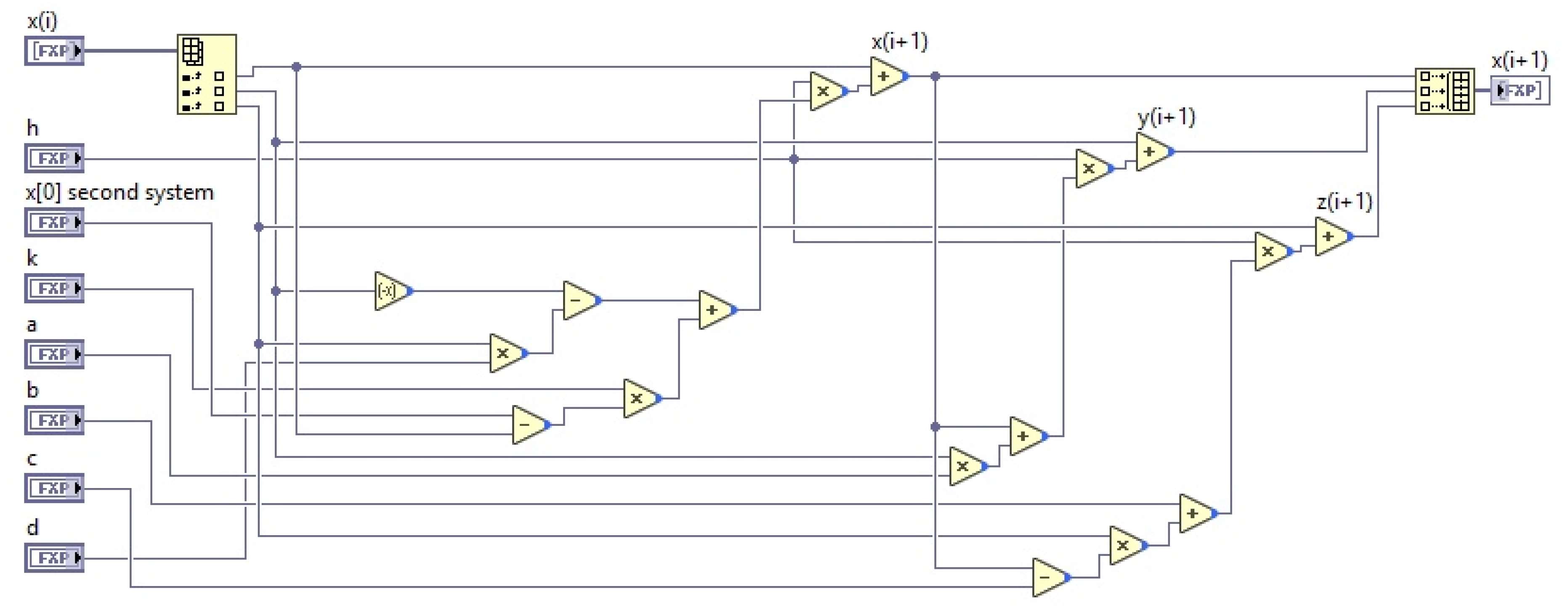
  • A system with approximate parameters was simulated using the 8th order semi-implicit ECD method [18] to obtain the same number of points as the reference record had. Then a total root mean square error was calculated using the following weighted formula:
    E = i N [ 0.3 ( x x r e f ) 2 + ( y y r e f ) 2 + 10 ( z z r e f ) 2 ]  
  • The weight coefficients enhanced the convergence of the optimization algorithm.
The parameters were tuned using the Hooke–Jeeves method [19], implemented in MATLAB 2017b (40502181, ETU-LETI, St. Petersburg, Russia).
An example of the optimization results is shown in Figure 3. For the circuit with nominal parameters, System (2), it was found that exact parameters should be as follows:
a = 0.204 , b = 0.200 , c = 5.411 , d = 1.888
To process the data obtained from the analog circuit in MATLAB, we used a digital scope with a 16-bit resolution between −10 V and 10 V and with sampling up to 250 kS/s. This data can be considered as analog, because the measurements have not affected the oscillations mode.
An ability to control the circuit parameter digitally made it possible to obtain bifurcation diagrams of the analog circuit and to compare them with the computer simulation bifurcation diagram. The bifurcation diagram, built when parameter b was varied, is presented in Figure 4. One can see a good correspondence of the analog circuit and computer model bifurcation diagrams. Notice that there is very high sensitivity of the bifurcation diagram appearance and exact parameter values of the Rössler systems, up to a 3rd sign after the decimal point.

3. Digital–Analog Chaotic Oscillators Synchronization

Synchronization of two Rössler oscillators may be performed by a coupling procedure [20]. Using this technique, unidirectional (master-slave) and bidirectional coupling can be established. Assume the couple of synchronized oscillators, as follows:
x ˙ 1 = y 1 d z 1 + k ( x 2 x 1 ) y ˙ 1 = x 1 + a y 1 z ˙ 1 = b + z 1 ( x 1 c ) x ˙ 2 = y 2 d z 2 + k ( x 1 x 2 ) y ˙ 2 = x 2 + a y 2 z ˙ 2 = b + z 2 ( x 2 c )  
where k is a coupling constant. If k in one of equation is equal to zero, this corresponds to the master–slave synchronization case. Figure 5 shows the synchronization between two analog Rössler oscillators.
To implement the digital chaotic generator, we chose the Euler–Cromer numerical integration method [18]. The computational scheme of the Rössler system solved by the Euler–Cromer method is as follows:
x [ 0 ] = x [ 0 ] + h ( x [ 1 ] d x [ 2 ] + k ( x s x [ 0 ] ) ) , x [ 1 ] = x [ 1 ] + h ( x [ 0 ] + a x [ 1 ] ) , x [ 2 ] = x [ 2 ] + h ( b + x [ 2 ] ( x [ 0 ] c ) ) .  
where h is the integration step, and a , b , c , d are the system parameters. Array x contains the slave system state variables and x s is a first state variable of a master system.
The chaotic signal generator, System (5), was implemented on the FPGA of Xilinx Zynq-7010 system-on-chip module, using NI LabVIEW FPGA Module software (see Figure 6). This graphical code was used to generate FPGA bitmap automatically for the chosen target platform.
Nonlinear parameters of the digital implementation were selected according to the results of the optimization procedure. Then, the analog–digital coupling was established and compared to the analog–analog synchronization. The phase portraits of the corresponding synchronization errors are presented in Figure 7.
Figure 7a demonstrates the data obtained in the literature [14]. Figure 7b shows the result of synchronization after the identification procedure. One can see that the application of a proper identification technique allows for reducing the synchronization error. Table 1 shows the quantitative estimates.

4. Discussion and Conclusions

Our study convincingly demonstrates the practical possibility of synchronization between digital and analog chaotic systems, with an accuracy higher that in the case of the analog–analog synchronization. The obtained results can be used in a variety of practical applications. For chaos-based sensors, one can develop novel hardware architectures, allowing for the real-time identification of nonlinearity parameters. For the encryption systems, some new mechanisms can be proposed to improve their strength, by exchanging data between the analog and digital oscillators. Communication systems based on analog–digital chaotic synchronization can show a better resistance to interferences through the application of DSP algorithms, while the analog part will be responsible for receiving data from the media.
A further investigation will be dedicated to transferring the identification algorithms to embedded systems, as well as the implementation of specific technical systems that exploit the proposed synchronization technique.

Author Contributions

Conceptualization, D.B.; data curation, A.T.; investigation, T.K. and D.B.; methodology, D.B. and A.K.; project administration, D.B.; resources, V.A.; software, T.K., V.A., A.K., and A.T.; validation, T.K. and V.A.; visualization, T.K.; writing (original draft), T.K. and A.K.; writing (review and editing), D.B. and A.T.

Funding

This research received no external funding.

Acknowledgments

Special thanks to Roman S. Tedoradze for making the circuit presented in Appendix A.

Conflicts of Interest

The authors declare no conflict of interest.

Appendix A

In this section, the schematic PCB layout and images of the experimental equipment described in Section 2 are shown.
Figure A1. Analog of the Rössler modeling circuit with digital control of nonlinear parameters.
Electronics 07 00123 g0a1
Figure A2. PCB design of analog chaotic system simulation circuit: (a) first layer and (b) second layer.
Electronics 07 00123 g0a2
Figure A3. Chaotic system simulation circuit design: (a) 3D model and (b) final circuit.
Electronics 07 00123 g0a3

References

  1. Jovic, B. Application of Chaotic Synchronization to Secure Communications. Synchronization Techniques for Chaotic Communication Systems. Signals and Communication Technology; Springer International Publishing: Berlin/Heidelberg, Germany, 2011; pp. 135–169. [Google Scholar]
  2. Murillo-Escobar, M.A.; Cruz-Hernández, C.; Abundiz-Pérez, F.; López-Gutiérrez, R.M. Implementation of an improved chaotic encryption algorithm for real-time embedded systems by using a 32-bit microcontroller. Microprocess. Microsyst. 2016, 45, 297–309. [Google Scholar] [CrossRef]
  3. Teodorescu, H.N.; Cojocaru, V. Biomimetic chaotic sensors for water salinity measurements and conductive titrimetry emerging security technologies. In Proceedings of the 2012 Third International Conference on Emerging Security Technologies (EST), Lisbon, Portugal, 5–7 September 2012; pp. 182–185. [Google Scholar]
  4. Silva, M.; Nepomuceno, E.; Amaral, G.; Martins, S.; Nardo, G. Exploiting the rounding mode of floating-point in the simulation of Chua’s circuit. Electr. Eng. Syst. Sci. 2018, 7, 185–193. [Google Scholar] [CrossRef]
  5. Nepomuceno, E.G.; Martins, S.A.; Silva, B.C.; Amaral, G.F.; Perc, M. Detecting unreliable computer simulations of recursive functions with interval extensions. Appl. Math. Comput. 2018, 329, 408–419. [Google Scholar] [CrossRef]
  6. Karimov, T.I.; Butusov, D.N.; Pesterev, D.O.; Predtechenskii, D.V.; Tedoradze, R.S. Quasi-chaotic mode detection and prevention in digital chaos generators. In Proceedings of the 2018 IEEE Conference of Russian Young Researchers in Electrical and Electronic Engineering (EIConRus), Moscow, Russia, 29 January–1 February 2018; pp. 303–307. [Google Scholar]
  7. Mendes, E.M.; Nepomuceno, E.G. A very simple method to calculate the (positive) largest Lyapunov exponent using interval extensions. Int. J. Bifurcation. Chaos 2016, 26, 1650226. [Google Scholar] [CrossRef]
  8. Mladenov, V.; Kirilov, S.A. Memristor Model with a Modified Window Function and Activation Thresholds. In Proceedings of the 2018 IEEE International Symposium on Circuits and Systems (ISCAS), Florence, Italy, 27–30 May 2018; pp. 1–5. [Google Scholar]
  9. Butusov, D.N.; Ostrovskii, V.Y.; Karimov, A.I.; Belkin, D.A. Study of two-memcapacitor circuit model with semi-explicit ODE solver. In Proceedings of the 2017 21st Conference of Open Innovations Association (FRUCT), Helsinki, Finland, 6–10 November 2017; pp. 64–70. [Google Scholar]
  10. Saito, T.; Nakagawa, S. Chaos from a hysteresis and switched circuit. Philos. Trans. R. Soc. A 1995, 353, 47–57. [Google Scholar] [CrossRef]
  11. Zeraoulia, E.; Sprott, D.C. Robust Chaos and Its Applications; World Scientific: Singapore, 2012; Volume 79. [Google Scholar]
  12. Pham, V.T.; Volos, C.; Jafari, S.; Wang, X.; Kapitaniak, T. A simple chaotic circuit with a light-emitting diode. Optoelectron. Adv. Mater. Rapid Commun. 2016, 10, 640–646. [Google Scholar]
  13. Miller, D.A.; Dozeman, M.; Westphal, G.; Abdel-Qader, K. A hybrid analog/digital circuit for experiments in controlling chaos. In Proceedings of the 2002 45th Midwest Symposium on Circuits and Systems (MWSCAS), Tulsa, OK, USA, 4–7 August 2002; pp. 1–188. [Google Scholar]
  14. Butusov, D.N.; Karimov, T.I.; Lizunova, I.A.; Soldatkina, A.A.; Popova, E.N. Synchronization of Analog and Discrete Rössler Chaotic Systems. In Proceedings of the 2017 IEEE Russia Section Young Researchers in Electrical and Electronic Engineering Conference (ElConRus), Saint-Petersburg, Russia, 1–3 February 2017; pp. 265–270. [Google Scholar]
  15. Chang, W.D. Parameter identification of Rossler’s chaotic system by an evolutionary algorithm. Chaos Solitons Fractals 2006, 29, 1047–1053. [Google Scholar] [CrossRef]
  16. Lacerda, M.J.; Martins, S.A.M.; Nepomuceno, E.G. Structure Selection Based on Interval Predictor Model for Recovering Static non-linearities from Chaotic Data. IET Control Theory Applications. 16 April 2018. Available online: http://digital-library.theiet.org/content/journals/10.1049/iet-cta.2017.1033 (accessed on 17 April 2018).
  17. Rössler, O.E. An equation for continuous chaos. Phys. Lett. A 1976, 57, 397–398. [Google Scholar] [CrossRef]
  18. Butusov, D.N.; Karimov, A.I.; Tutueva, A.V. Hardware-targeted semi-implicit extrapolation ODE solvers. In Proceedings of the 2016 International Siberian Conference on Control and Communications (SIBCON), Moscow, Russia, 12–14 May 2016; pp. 1–6. [Google Scholar]
  19. Hooke, R.; Jeeves, T.A. Direct search solution of numerical and statistical problems. J. Assoc. Comput. Mach. 1961, 8, 212–229. [Google Scholar] [CrossRef]
  20. Buscarino, A.; Frasca, M.; Branciforte, M.; Fortuna, L. Synchronization of two Rossler systems with switching coupling. Nonlinear Dyn. 2017, 88, 673–683. [Google Scholar] [CrossRef]
Figure 1. Visualization of the dynamics of System (1): (a) three-dimensional (3D) attractor and (b) time domain plot.
Electronics 07 00123 g001
Figure 2. Analog of Rössler oscillator, System (1), model.
Electronics 07 00123 g002
Figure 3. Identification of analog system dynamic using the Hooke–Jeeves parameter tuning method: (a) 3D attractor and (b) state variable z time domain plot.
Electronics 07 00123 g003
Figure 4. Comparison of analog (blue) and digital (yellow) systems bifurcation diagrams after identification with parameters, System (3), and varying parameter b.
Electronics 07 00123 g004
Figure 5. Coupled Rössler oscillators implemented as an analog circuit.
Electronics 07 00123 g005
Figure 6. Block diagram of FPGA chaos generator based on the Rössler system, made in NI LabVIEW 2017 FPGA software.
Electronics 07 00123 g006
Figure 7. Phase portraits of synchronization error for analog–analog (A–A) and digital–analog (D–A) synchronized couples: (a) without an identification of digital model parameters, and (b) after identification using the proposed technique, the synchronization error is significantly less.
Electronics 07 00123 g007
Table 1. Comparison of root mean square (RMS) errors of different oscillator couples.
Synchronized CoupleRMS Error, %
Analog–analog1.4
Analog–digital with manual tuning0.6
Analog–digital with identification0.36

