1. Introduction
Securing sensitive information on low-cost satellite applications has become a major challenge for the space industry. Typical approaches that include very expensive cryptographic primitives, non-volatile memory and analogous blocks cannot be afforded in these small space systems. In this context, commercial Field Programmable Gate Arrays (FPGAs) have turned out to be a good solution due to their flexibility and cost. Among their many uses, FPGAs can be dedicated to ensuring secure satellite data.
A popular solution to provide security in resource constrained applications, such as those using FPGAs, is on-chip Physical Unclonable Functions (PUFs). PUFs are a very promising security primitive used for authentication and key generation in IC and FPGAs. These security primitives are based on the impossibility of creating two physically exactly identical ICs due to the influence of random and uncontrollable effects during the manufacturing process. These uncontrollable influences leave measurable random marks on some features which possess the potential to generate encryption keys directly associated to a device [
1]. Thus, PUFs work as an unclonable specific feature that can identify a circuit, just as a fingerprint can identify a human being. Among the various device properties that can be used for this purpose, delay-based PUFs deserve special attention due to their straightforward implementation. A delay-based PUF exploits the delay dependency on the random process variations [
2]. Well-known examples of this type of PUF are the Arbiter PUF [
3] and the Ring Oscillator PUF [
2].
PUFs can be used to solve an important issue related to the generation of secure encryption keys in satellite communications, removing the necessity for key storage. Nonetheless, as PUF response depends on some circuit features that may be affected by the operational conditions; it is important to assert the suitability of these primitives in harsh environments subjected to ionizing radiation. Ionizing radiation induces charges in the semiconductor material that can be trapped in the oxide, altering the electrical characteristics of electronic devices. This effect, known as Total Ionizing Dose (TID), is cumulative and produces a gradual degradation of major electrical parameters, such as threshold voltage and leakage current, that can eventually result in device failure at a certain dose. To the best of our knowledge, the effects of TID in delay-based PUFs have not been studied before. There is one work that studies the TID effects in a CMOS silicon PUF based on transistor breakdown [
4].
In this work, we evaluate the effects of ionizing radiation on a well-known delay-based PUF [
2] implemented in a SRAM-FPGA. To that end, we have performed an extensive test with two different devices exposed to a radiation source, periodically collecting the PUF response as TID increased. All the external influences that can affect the PUF response (temperature, humidity, voltage, etc.) were controlled. Several major quality metrics have been used in order to assess the impact of radiation in the PUF response.
The remainder of this paper is organized as follows.
Section 2 introduces the RO-PUF under study and the typical effects of ionizing radiation on SRAM-FPGAs.
Section 3 describes the implementation of the RO-PUF and the TID test setup.
Section 4 reports the impact of the ionizing dose on the RO-PUF. Several metrics are presented and analyzed in this section. Finally,
Section 5 summarizes the conclusions of this work.
2. Background
2.1. Ring Oscillator Based PUF
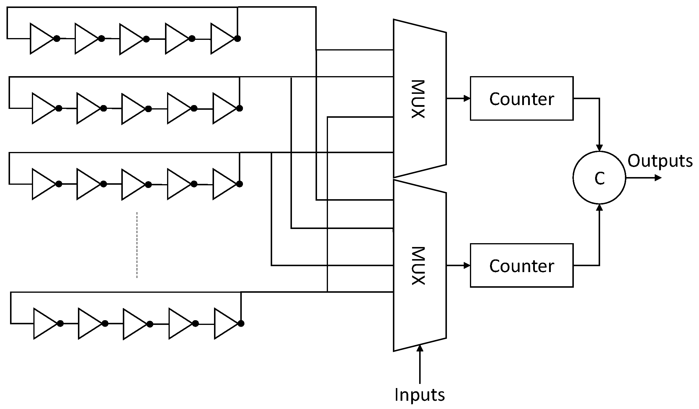
A Ring Oscillator (RO) is a delay loop that oscillates at a particular frequency. Thanks to its straightforward implementation in FPGAs, ROs have been widely used in the implementation of secure primitives such as true random number generator (TRNG). RO-PUFs are delay-based PUFs that use Challenge-Response scheme as a chip authentication mechanism. A traditional RO-PUF [
2] makes use of many identically laid out ROs to quantify the manufacturing variability. RO oscillation frequencies depend on (i) fixed conditions established at the design phase (i.e., number of stages, place&route, etc.); (ii) random process variations (that once manufactured are fixed for each single device); (iii) dynamic conditions derived from the operation environment (i.e., supply voltage, temperature, surrounding logic, etc.).
Figure 1 depicts the traditional RO-PUF scheme [
2] that consists of many identical ROs, counters and comparators.
During the authentication process, a pair of ROs (selected by a user challenge) are quantized by measuring and comparing the RO frequencies
and generating a response bit
r:
An n-bit signature of the chip is computed from n different comparisons between RO frequencies. The quality of the PUF is evaluated by analysing the signatures. In most of the literature, major security metrics like uniformity, reliability and uniqueness are used to assess the PUF quality [
5].
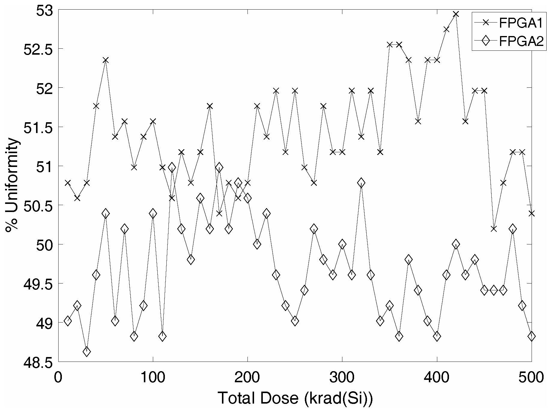
Uniformity is a metric related to the entropy of the system. This metric estimates the ratio of ‘1’ vs. ‘0’ in all the response bits generated by a PUF. The uniformity is computed as follows for an n-bit PUF response:
where
is the l-th bit of an n-bit PUF response. An uniform distribution of 0’s and 1’s (50%) is expected in PUFs that have full entropy.
Reliability is a metric that quantifies how stable the PUF response is over varying operating conditions (voltage, temperature, aging, etc.). To that end, a specific challenge is applied to the RO-PUF in order to obtain an n-bit reference response
for normal conditions (room temperature, ideal power supply voltage). The same n-bit response is collected at different operating conditions
. Finally, the reliability is obtained using the Hamming distance (HD) analysis of responses.
where
x is the number of samples for each condition and
is the y-th sample of
. A lower value of intra-die HD leads to a higher reliability.
Uniqueness is a measure of how different the PUF responses of different chips among a set of chips are. The uniqueness of a population of k-chips is obtained by computing the inter-HD of the n-bit responses for the same challenge:
where
and
are the PUF responses of chips
i and
j (
). An ideal uniqueness of 50% is desired for the complete set of chips.
2.2. TID on SRAM FPGAs
TID effects on SRAM-based FPGAs, including non-radiation hardened, have been widely studied in recent years [
6,
7,
8]. TID causes a degradation of the transistors as ionizing radiation accumulates on the component. This degradation leads to creating trapped charges that will slowly affect the electrical parameters of the device (threshold voltage
and leakage current) [
9]. In this context, NMOS and PMOS transistors behave differently. The trapped charges will negatively affect the threshold voltage increasing the leakage current in NMOS transistors. Conversely, in PMOS transistors the threshold voltage will be increased and the leakage reduced. In addition, a deterioration of noise parameters can be observed [
10]. All these effects are dependent on many factors such as dose rate, the type of radiation applied, temperature, etc.
At device level, an increase of the propagation delay of the circuits instantiated in the FPGA is the main aspect to consider. Faults can appear when the timing constraints are violated due to this increment [
11].
3. Experimental Setup
3.1. Device Under Test
The radiation experiments have been carried out on two Xilinx XC3S500E FPGA, manufactured on 90 nm CMOS technology. In the remainder of the paper, these Devices Under Test (DUTs) are referred to as FPGA1 and FPGA2. The clock is set using the on-board 50 MHz crystal oscillator. Two high precision voltage sources (programmable HP 66103A DC power modules) have been used in order to set and monitor the core voltage (1.2 V) and the I/O voltage (3.3 V).
A conventional RO-PUF consisting of 512 identically laid-out ROs has been implemented. Each of the ROs consists of four inverters and a NAND gate, the latter being able to enable/disable the oscillation. A hard macro that occupies one Configurable Logic Block (CLB) has been created in order to guarantee the same placement and routing for all the ROs. This hard macro has been replicated in the middle of the FPGA creating a 16 × 32 array. During the experiment, each RO is activated at a time during 13,000 clock cycles using its enable signal. The rest of the RO-PUF logic (multiplexers, counters, decoders, etc.) have been implemented in other FPGA zones in order to limit the impact of the surrounding logic on RO frequencies. An RS232 communication protocol has been used in order to transfer the measured RO frequencies to the host computer. A CRC has been implemented in order to ensure the integrity of the communication.
The operating conditions of the room (temperature, pressure and humidity) have been controlled in order to guarantee that these conditions do not affect the RO frequencies.
3.2. TID Setup
The TID tests have been performed at the RADLAB facility, the Gamma Radiation Laboratory installed in the Centro Nacional de Aceleradores (CNA), Spain. The RADLAB [
12,
13] is based on a Co-60 radioactive source, placed into a Gamma beam X200 irradiator. The average value for the photons energy is 1.25 MeV, which is usually established for testing purposes.
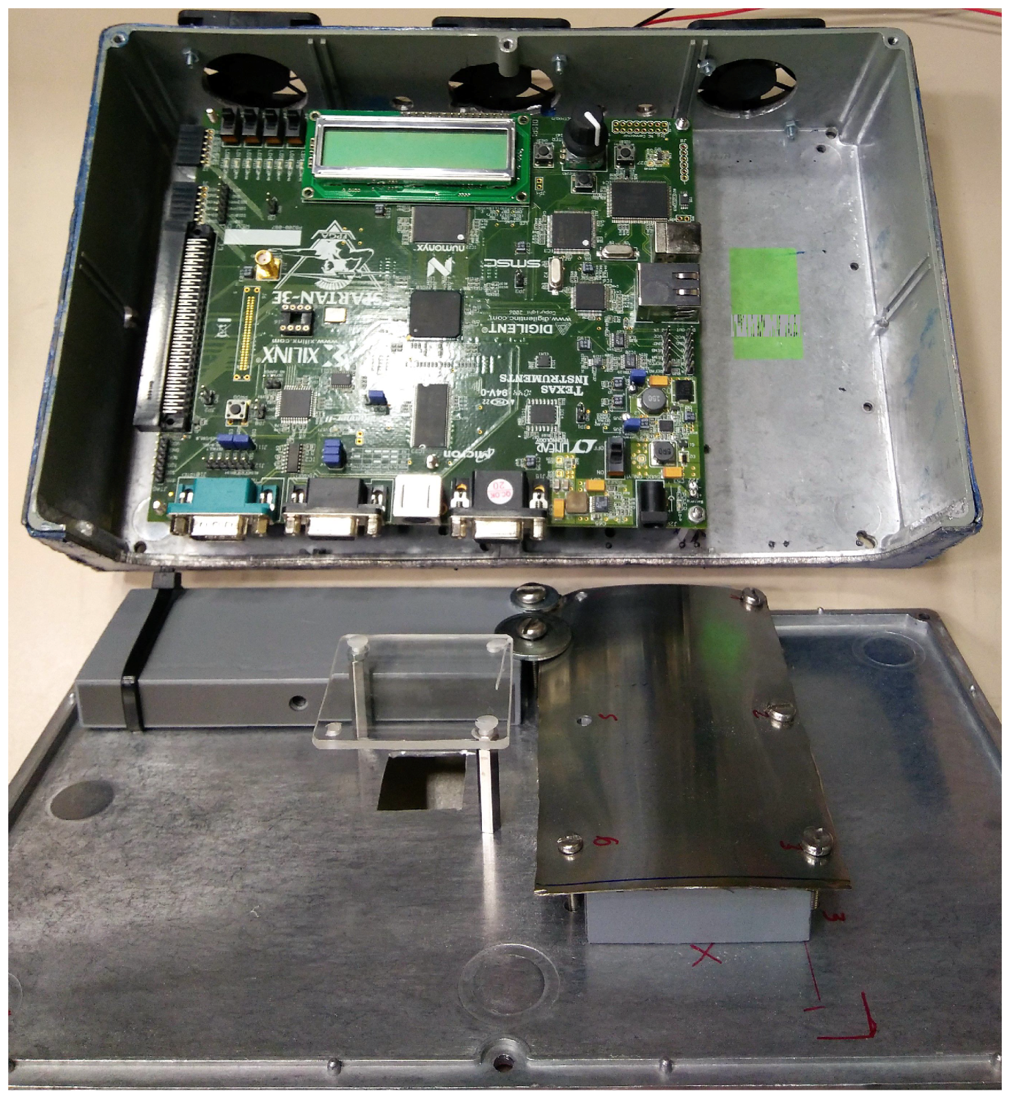
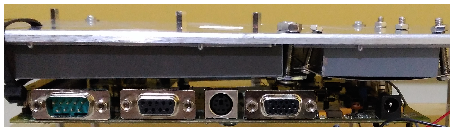
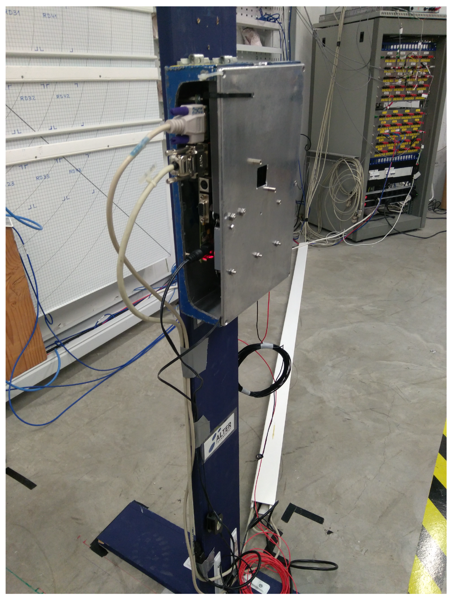
The irradiator has a conical opening which contains a variable collimator, providing different square irradiation fields. During a first irradiation setup, the maximum irradiation field was used and no shielding was applied on the board, so all the components of the PCB were exposed to radiation, not only the DUT (FPGA). As a consequence, some issues were observed before detecting any effect in the DUT. For the subsequent campaigns, the irradiation field was reduced to focus the main gamma beam on the FPGA under study. Moreover, the setup was additionally improved with a custom partial shielding on the board, significantly decreasing the dose rate on the most sensitive components of the PCB (
Figure 2 and
Figure 3 ).
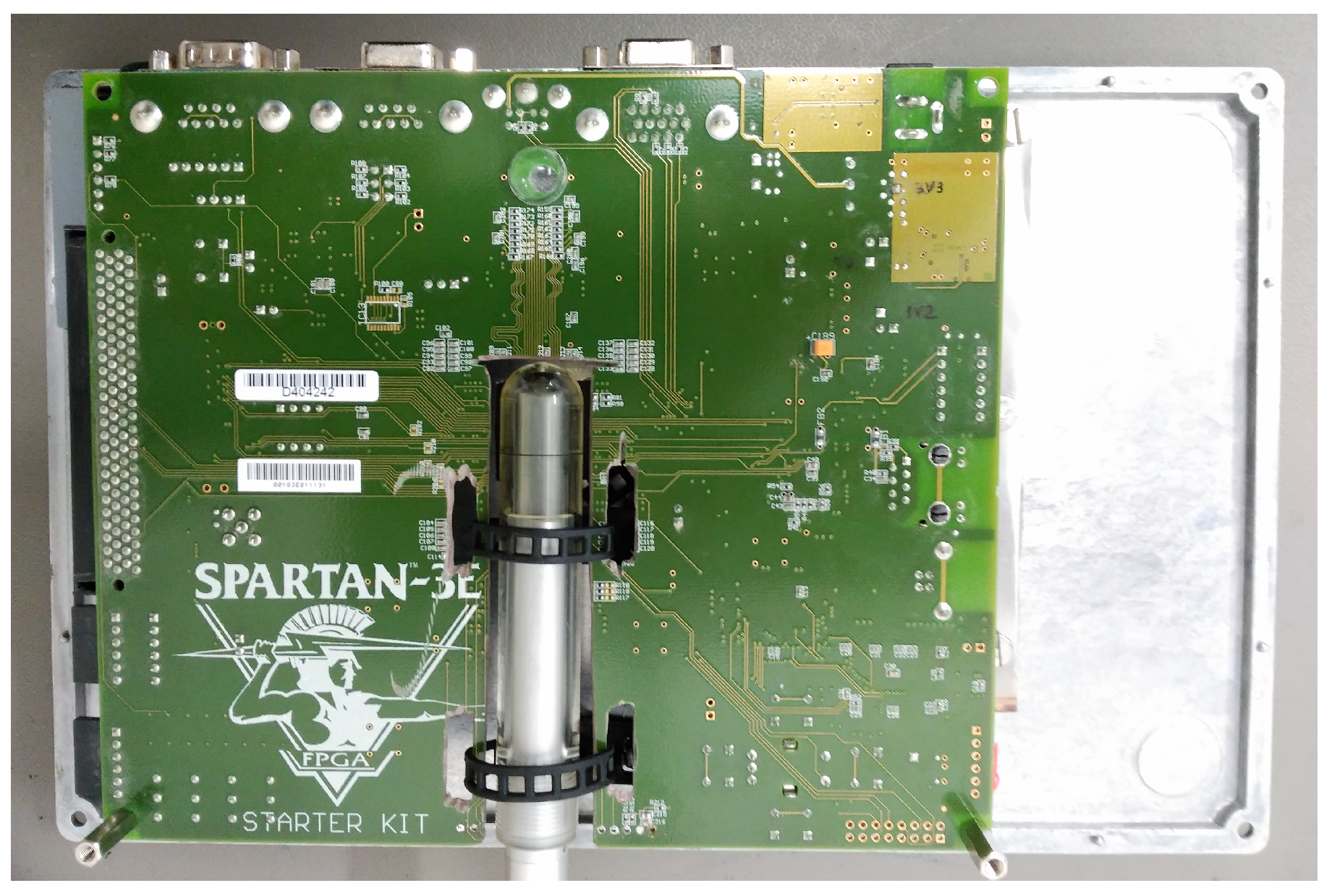
Since the DUT is located in one specific position of the PCB submitted to radiation, a dummy board was placed for each setup preparation in the same position as the SAMPLE in order to carry out the dosimetry (
Figure 4), that is, to measure the dose rate on the DUT, before starting the irradiation test.
The dosimetry system is composed by a Farmer ionization chamber connected to the UNIDOS Webline electrometer, both of them by PTW. First air kerma rate is obtained and the dose rate in silicon (Si) is calculated taking into account the conversion factors. The dose rate uniformity in the radiation field was better than 95% and the expanded uncertainty associated with the measurement was .
The dosimetry and the irradiation run were performed using a filter box, with the DUT inside, according to the TID standard from European Space Agency [
12]. This container has 1.5 mm Pb (lead) with an inner lining of 2 mm Al (aluminium). The front cover is made of Al, except in the region close to the DUT, where the build-up material is polymethilmetacrilate (PMMA). In
Figure 5 is depicted the final setup.
The FPGA1 and FPGA2 were exposed to a total dose of 500 krad(Si), with the dose rates of 5.2 krad(Si)/h and 5.3 krad(Si)/h, respectively.
4. Experimental Results and Discussion
This section describes the results of the irradiation experiments on the two DUTs.
4.1. FPGA Parameters and Functionality
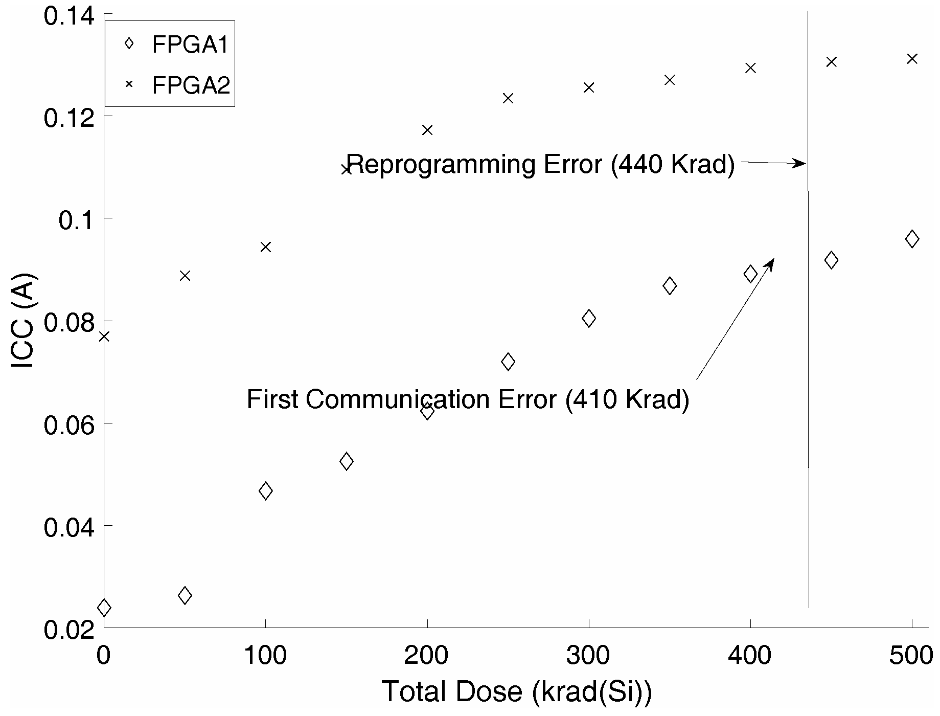
The core currents and voltages were continuously measured during the entire experiment. The pre-irradiation operation currents were measured to be 23.9 mA for FPGA1 and 29.09 mA for FPGA2. At the end of the experiment [500 krad(Si)], the currents reached 95.97 mA and 83.35 mA, respectively. These internal core currents are within the limits of the vendor recommendations for this FPGA (typical: 25 mA; maximum: 106 mA). Nevertheless, the first failure was registered at 410 krad(Si) in FPGA1. This failure was related to the RS232 communication protocol and a reprogramming of the FPGA was necessary in order to recover normal functionality. This kind of error was reproduced until the end of the experiment. In FPGA2, no failures were registered. Both DUTs could not be reconfigured any more after the deposited dose reached 440 krad(Si). The faulty behaviour that appeared only in FPGA1 can be explained by the batch difference on the DUT or the lower dose rate (the results typically show marginally higher dose degradation threshold at lower dose rates [
14]).
Figure 6 depicts the core currents of FPGA1 and FPGA2 through the irradiation experiment. It is noteworthy that for both DUTs the core current increased linearly with the dose. This increase of leakage current is fully accounted for in the creation of electron-hole pairs due to the ionization of SiO
[
15].
4.2. Delay Variation of the RO Loop
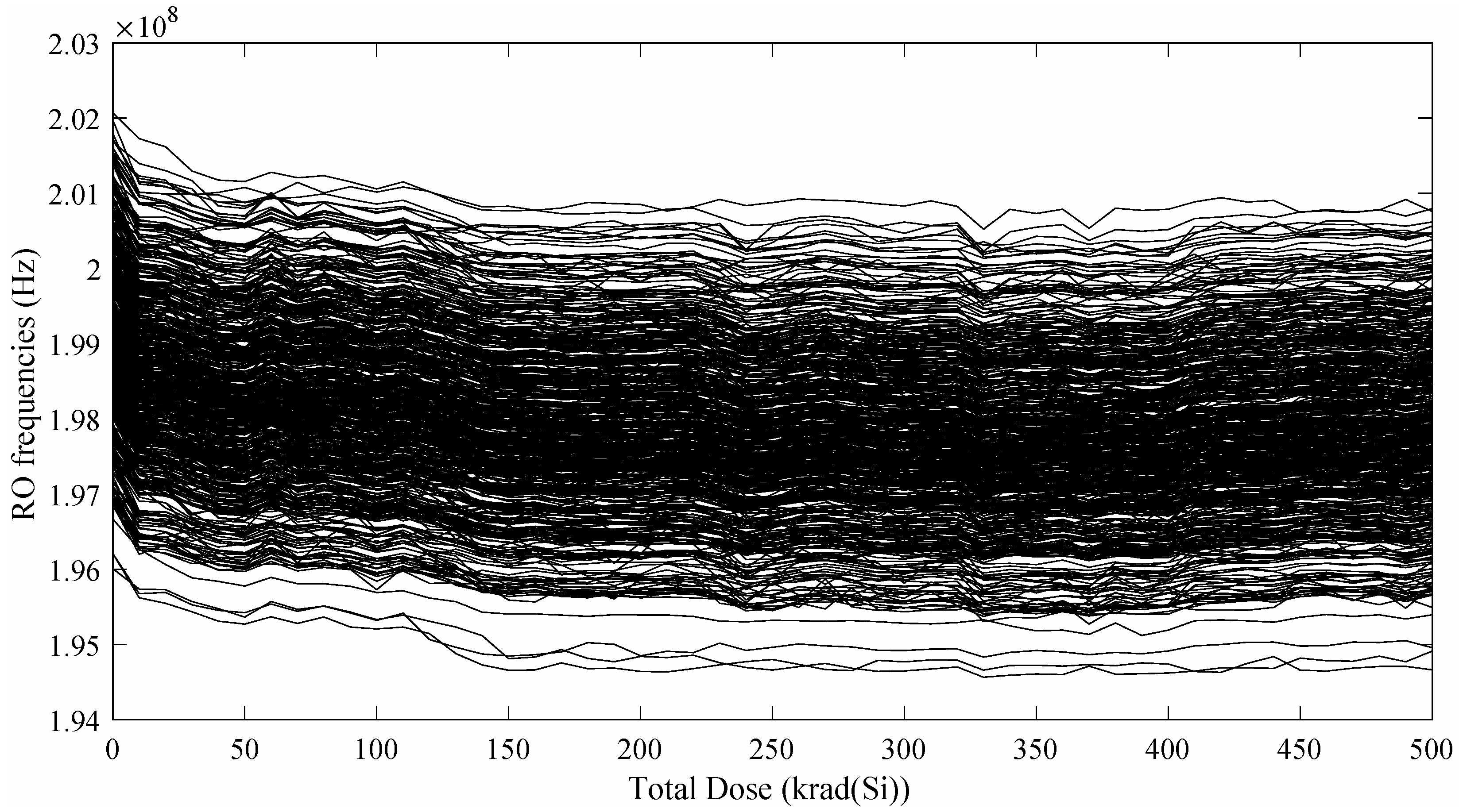
RO frequencies play a key role in the RO-PUF authentication scheme, therefore they have been subjected to exhaustive analysis during the whole experiment. For each RO, we have carried out 100 frequency acquisitions in order to improve the measurement error by averaging the values. At pre-irradiation conditions, the average RO frequencies of FPGA1 and FPGA2 are 196.12 MHz and 199.16 MHz respectively. At the end of the experiment [500 krad(Si)], the average RO frequencies of FPGA1 and FPGA2 have decreased to 195.1 MHz (0.5%) and 197.92 MHz (0.6%) respectively.
Figure 7 shows how the 512 RO average frequencies of FPGA2 changed during the experiment. It can be appreciated that after a first sharp decrease at 10 krad(Si), all the ROs follow the same tendency. It is also worthy of note that there are not many intersections between the different lines, which indicates a good frequency stability. These results are very similar to those reported in [
16], where the effects of ageing in a RO-PUF were studied.
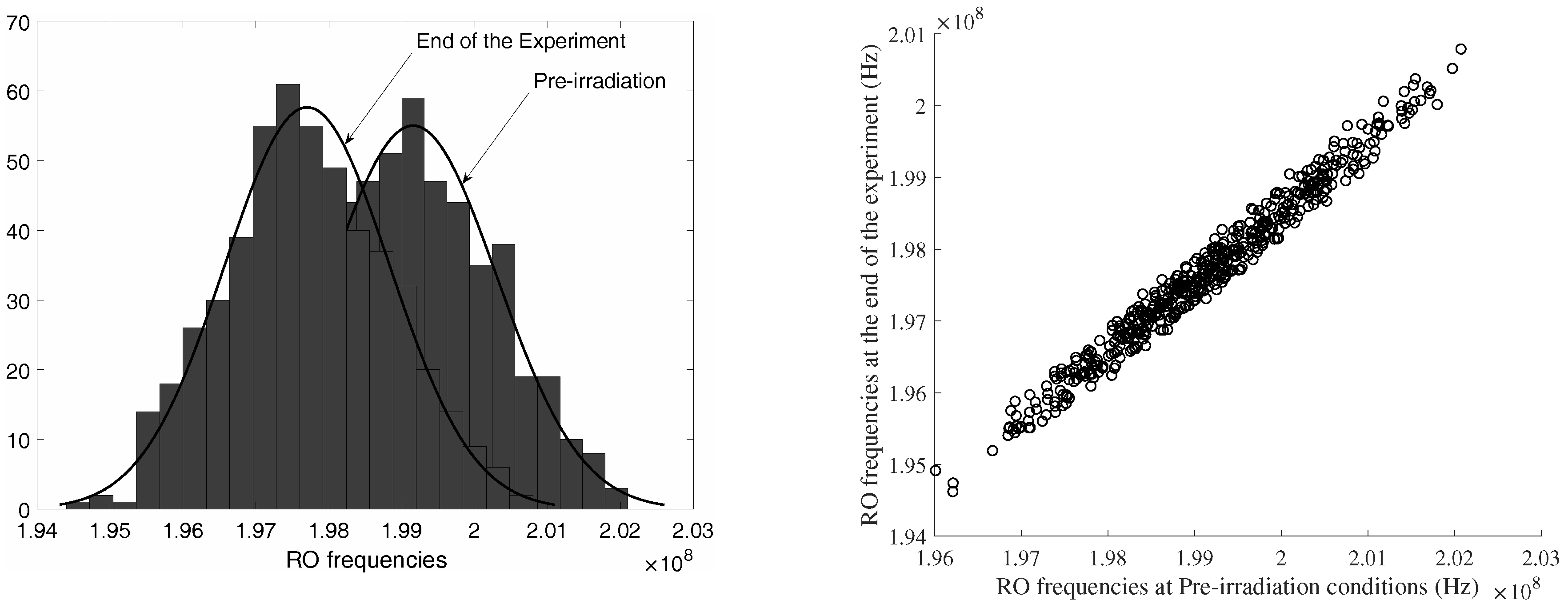
Figure 8 shows the distribution of the average frequencies at pre-irradiation conditions and at the end of the experiment. Once again, the frequency stability can be highlighted. The results for FPGA1 are analogous to those depicted in
Figure 7 and
Figure 8.
4.3. RO-PUF Quality Factors
We have calculated the main metrics related to PUF quality in order to evaluate the suitability of the RO-PUF for space applications. To that end, a 511-bit response has been generated for each accumulated doses. This 511-bit response is extracted by comparing the average frequencies of adjacent pairs of ROs in the array.
4.3.1. Uniformity
Figure 9 depicts the uniformity of the PUF response during the experiment. For both DUTs, the response bits are fairly evenly distributed among ‘0’ and ‘1’, showing almost an ideal distribution throughout the entire experiment. The average number of 1’s in the PUF response for FPGA1 and FPGA2 are 51.43% and 49.61%, respectively.
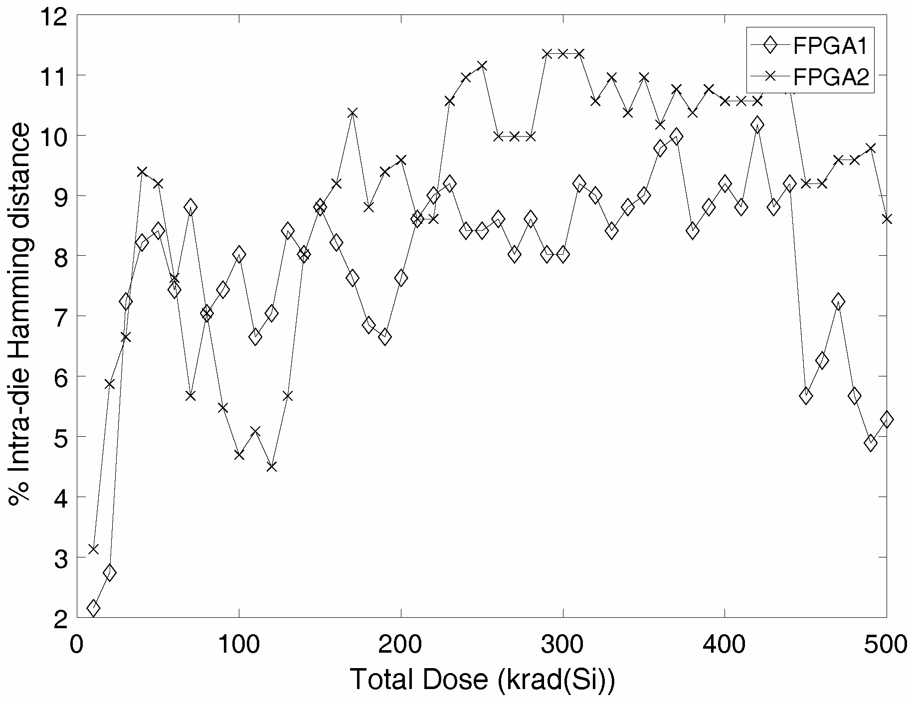
4.3.2. Reliability
Figure 10 shows the intra-die Hamming distance calculated using Equation (
2). The pre-irradiated 511-bit response has been set as the reference response. In both FPGAs, the initial intra-die HD is low (>3%) and it increases with the accumulated dose. This means that there is an increasing degradation of the RO performance that is proportional to the radiation dose.
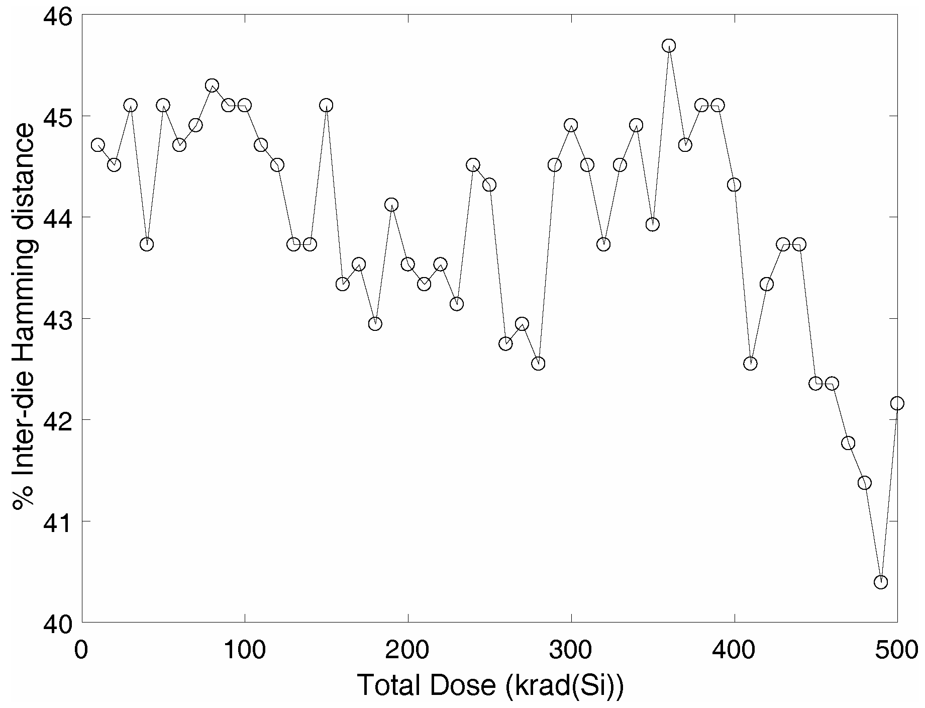
4.3.3. Uniqueness
Figure 11 presents the inter-die Hamming distance obtained using Equation (
3). Once again, a loss on the uniqueness can be observed and is proportional to the accumulated dose.
4.4. Result Analysis
The increase in the core currents are consistent with other results reported in the literature for the same FPGA [
17]. In the case of FPGA1, the first failure occurred at 410 krad(Si), which is also similar to the first failure reported in [
17], where the DUT worked properly until 345 krad(Si). Regarding the RO-frequencies, the experiments have shown that there is a good stability on the frequencies and the changes due to the accumulated dose are negligible.
On the other hand, the quality metrics show that the accumulated dose makes the responses produced by the PUF unreliable. Nonetheless, as the uniformity metric shows, the randomness of the response remains unaffected by the total dose. This may be due to the decrease of the noise parameters that have a direct influence on the randomness. Reliability is the key metric to evaluate after the deployment of PUFs in space. If at pre-irradiation conditions all the metrics have acceptable values, only a decrease in the reliability due to ionizing radiation can affect the rest of the metrics. In this case, the reliability metric shows a little degradation that can be corrected using some typical countermeasures such as using only RO pairs with maximal frequency difference [
2] or using quantizers with reliability guarantees [
18]. Regarding uniqueness, as a collateral effect of unreliability, the results also show a degradation of the metric.
All in all, we can conclude that total ionizing dose has a perceptible effect on the quality of the RO-PUF response. However, with some post-processing, this RO-PUF could be used for space applications.
5. Conclusions
RO-PUFs leverage minor delay variations that exist between devices to support security functions such as authentication and key generation. As TID significantly affects propagation delays, the response of an RO-PUF may be jeopardized in space. In this work, we have performed a comprehensive analysis of the effects of ionizing radiation on the quality of RO-PUFs implemented in FPGAs. RO-PUFs responses were collected as dose accumulated in order to evaluate uniformity, reliability, uniqueness and frequency stability. The external environment was controlled and the core currents and voltages were continuously measured to ensure the results were not biased.
Experimental results showed that RO frequencies show good stability and that the randomness of the response is not affected by TID. However, the reliability and uniqueness of the response shows a little degradation. Nevertheless, this degradation can be corrected by using some typical countermeasures. With these corrections, we can conclude that RO-PUFs implemented in FPGAs can be used in space applications.
Author Contributions
Conceptualization, H.M. and L.E.; Methodology, H.M., P.M.-H. and Y.M.; Writing—Original Draft Preparation, H.M., P.M.-H., Y.M., L.E. and E.S.-M.
Funding
This work was partially supported by the Spanish Ministry of Economy and Competitiveness under contracts ESP2015-68245-C4-1-P and ESP-2015-68245-C4-4-P.
Acknowledgments
Thanks to the ALTER TECHNOLOGY company for making possible the monitoring and recording of the biasing and environmental test conditions during the irradiation test runs.
Conflicts of Interest
The authors declare no conflict of interest. The founding sponsors had no role in the design of the study; in the collection, analyses, or interpretation of data; in the writing of the manuscript, and in the decision to publish the results.
References
- Maes, R. Physically Unclonable Functions: Constructions, Properties and Applications, 1st ed.; Springer: Berlin, Germany, 2016. [Google Scholar]
- Suh, G.E.; Devadas, S. Physical Unclonable Functions for Device Authentication and Secret Key Generation. In Proceedings of the 44th ACM/IEEE Design Automation Conference, San Diego, CA, USA, 4–8 June 2007; pp. 9–14. [Google Scholar]
- Lee, J.W.; Lim, D.; Gassend, B.; Suh, G.E.; van Dijk, M.; Devadas, S. A technique to build a secret key in integrated circuits for identification and authentication applications. In Proceedings of the 2004 Symposium on VLSI Circuits. Digest of Technical Papers, Honolulu, HI, USA, 17–19 June 2004; pp. 176–179. [Google Scholar] [CrossRef] [Green Version]
- Wang, P.F.; Zhang, E.X.; Chuang, K.H.; Liao, W.; Gong, H.; Wang, P.; Arutt, C.N.; Ni, K.; McCurdy, M.W.; Verbauwhede, I.; et al. X-ray and Proton Radiation Effects on 40 nm CMOS Physically Unclonable Function Devices. IEEE Trans. Nucl. Sci. 2018, 65, 1. [Google Scholar] [CrossRef]
- Maiti, A.; Gunreddy, V.; Schaumont, P. A Systematic Method to Evaluate and Compare the Performance of Physical Unclonable Functions. In Embedded Systems Design with FPGAs; Springer: New York, NY, USA, 2013; pp. 245–267. [Google Scholar] [CrossRef]
- Barnaby, H.J. Total-Ionizing-Dose Effects in Modern CMOS Technologies. IEEE Trans. Nucl. Sci. 2006, 53, 3103–3121. [Google Scholar] [CrossRef]
- Yao, X.; Hindman, N.; Clark, L.T.; Holbert, K.E.; Alexander, D.R.; Shedd, W.M. The Impact of Total Ionizing Dose on Unhardened SRAM Cell Margins. IEEE Trans. Nucl. Sci. 2008, 55, 3280–3287. [Google Scholar] [CrossRef]
- Zebrev, G.I.; Orlov, V.V.; Gorbunov, M.S.; Drosdetsky, M.G. Physics-based modeling of TID induced global static leakage in different CMOS circuits. Microelectron. Reliab. 2018, 84, 181–186. [Google Scholar] [CrossRef] [Green Version]
- Quinn, H. Radiation effects in reconfigurable FPGAs. Semicond. Sci. Technol. 2017, 32, 044001. [Google Scholar] [CrossRef]
- MacQueen, D.M. Total Ionizing Dose Effects on Xilinx Field-Programmable Gate Arrays. Master’s Thesis, University of Alberta, Edmonton, AB, Canada, 2000. [Google Scholar]
- Ma, N.; Wang, S.; Liu, D.; Peng, Y. A run-time built-in approach of TID test in SRAM based FPGAs. Microelectron. Reliab. 2016, 64, 42–47. [Google Scholar] [CrossRef]
- Morilla, Y.; Muniz, G.; Dominguez, M.; Martin, P.; Jimenez, J.; Praena, J.; Munoz, E.; Sanchez-Angulo, C.I.; Fernandez, G. New Gamma-Radiation Facility for Device Testing in Spain. In Proceedings of the 2014 IEEE Radiation Effects Data Workshop (REDW), Paris, France, 14–18 July 2014; pp. 1–5. [Google Scholar] [CrossRef]
- Costantino, A.; Muschitiello, M.; Zadeh, A.; Romero, G.F.; Holgado, P.M.; Morilla, Y.; Muniz, G.; Standaert, L.; Vanhees, J. Dosimetry Inter-Laboratory Comparison between ESTEC, CNA-ALTER/RADLAB, and UCL. In Proceedings of the 15th European Conference on Radiation and Its Effects on Components and Systems (RADECS), Moscow, Russia, 14–18 September 2015; pp. 1–8. [Google Scholar] [CrossRef]
- Fabula, J.; Bogrow, H. Total Ionizing Dose Performance of SRAM-based FPGAs and supporting PROMs. In Proceedings of the 2001 MAPLD International Conference, Laurel, MD, USA, 11–13 September 2001. [Google Scholar]
- Schwank, J.R.; Shaneyfelt, M.R.; Fleetwood, D.M.; Felix, J.A.; Dodd, P.E.; Paillet, P.; Ferlet-Cavrois, V. Radiation Effects in MOS Oxides. IEEE Trans. Nucl. Sci. 2008, 55, 1833–1853. [Google Scholar] [CrossRef]
- Maiti, A.; McDougall, L.; Schaumont, P. The Impact of Aging on an FPGA-Based Physical Unclonable Function. In Proceedings of the 21st International Conference on Field Programmable Logic and Applications, Chania, Greece, 5–7 September 2011; pp. 151–156. [Google Scholar] [CrossRef]
- Da Silveira, M.A.G.; Santos, R.B.B.; Leite, F.G.H.; Araujo, N.E.; Medina, N.H.; Porcher, B.C.; Aguiar, V.A.P.; Added, N.; Vargas, F. X-Ray-Induced Upsets in a Xilinx Spartan 3E FPGA. In Proceedings of the 15th European Conference on Radiation and Its Effects on Components and Systems (RADECS), Moscow, Russia, 14–18 September 2015; pp. 1–4. [Google Scholar] [CrossRef]
- Günlü, O.; Kernetzky, T.; İşcan, O.; Sidorenko, V.; Kramer, G.; Schaefer, R.F. Secure and Reliable Key Agreement with Physical Unclonable Functions. Entropy 2018, 20, 340. [Google Scholar] [CrossRef]
© 2018 by the authors. Licensee MDPI, Basel, Switzerland. This article is an open access article distributed under the terms and conditions of the Creative Commons Attribution (CC BY) license (http://creativecommons.org/licenses/by/4.0/).

 ,
, 


