1. Introduction
Lighting is energy-intensive since the amount of energy consumed for lighting purposes corresponds to 20–40% of the total energy consumption in buildings [
1,
2,
3]. Furthermore, the heat of the luminaires indirectly influences the total energy balance of a building, by increasing the load of the cooling system. Therefore, the reduction of the lighting load results in an additional reduction from 10% to 20% of the energy consumed for air-conditioning. Moreover, investing in energy-efficient lighting is one of the most effective ways to reduce CO
2 emissions [
4].
Microcontrollers are used in automatically controlled products and devices, since they make easier to digitally control devices and processes, reducing at the same time the cost and the size of the embedded control system as a whole. Today there exists a rapid development of such systems towards intelligent control units. Particularly, applications based on ARM processors and Linux operating systems in system automation are very popular [
5,
6]. The problem of providing efficient communication and control of vision systems has been intensively examined. Several systems and control algorithms have been proposed towards this direction [
7,
8,
9].
Embedded systems are widely used in real world applications. Embedded systems often reside in machines that are expected to run continuously for years without errors and in most cases recover automatically if an error occurs. This is crucial while the light controls have already malpractices [
10] and dimming should be continuous [
11]. Since the embedded system is dedicated to specific tasks, design engineers can optimize it to reduce the size and cost of the product and increase reliability and performance. Overall, embedded computer intelligent controllers play an important role in improving the performance of a camera control system [
12,
13].
Furthermore, such systems could be used for the development of new approaches for efficient lighting control systems [
14,
15,
16]. Quite often light controllers, based on microcontrollers and microprocessors use pre-defined hardware, which functions according to the program that does not have the flexibility of modification on real time basis. The embedded technology along with image processing techniques of image segmentation and thresholding could be used for light digital control purposes. Camera monitoring for control purposes is becoming more and more vital due to rapid development of hardware equipment as well as the software methods that support intelligent monitoring and analytics [
17,
18,
19,
20,
21,
22,
23]. Current research is motivated by this goal and is focused upon embedded camera control and its applications in lighting control systems. It constitutes a practical paradigm of the Internet of Things (IoT).
Advanced lighting control can reduce significant the energy consumption in buildings [
24]. Today, a large number of smart lighting control systems use luminaire-based sensing (e.g., multiple light and occupancy sensors), and apply various control algorithms and techniques (e.g., proportional-integral (PI) controllers, spatial controllers) to adapt the dimming levels of the luminaires to varying daylight levels. However, the lighting control using cameras and luminance values [
25,
26,
27,
28,
29,
30,
31,
32,
33] has seen increasing interest of not only the researchers but also building contractors. Typically, photosensors that are used for daylight harvesting control [
34,
35] and measure illuminance values are located for practical reasons on the ceiling of a room in an effort to minimize any interference with the activities taking place in the room. The performance of a photosensor that is placed on the ceiling is dependent on the ceiling-to-working plane illuminance ratio which is not constant during its operation throughout the day [
36,
37]. It is common practice in lighting control to keep the illuminance or luminance (for an image-based sensing system) level on the workplane constant against daylight variations [
38,
39]. A digital camera can be used as a substitute of photosensors to overcome their common problems [
10]. Digital sensors have more advantages compared to conventional photosensors concerning optimum position or spectral response [
36,
40].
Reviewing the literature, it must be mentioned that some of the approaches are similar to the image-based sensing system that is proposed in this research, because they utilize an image-based control system that enables collection of luminance or illuminance values in order to perform lighting control. Nevertheless, most of these works are based on a PC platform. For example, the work of Sarkar A. and Mistrick R. [
17] on a novel lighting control system integrating high dynamic range imaging and DALI, involved a control system consisting of an Omnivision CMOS sensor based on Intertec CEV38 camera evaluation board, which connects to a personal computer for calibration and programming. The control software module that was developed was not integrated into the hardware, so the overall control system was neither self-sufficient, nor a low-cost embedded system. The work of Sarkar et al. [
18] on integrated daylight harvesting and occupancy detection using digital imaging, involved a high dynamic range CMOS video camera that integrated daylight harvesting and occupancy sensing functionalities, based on spectral reflectance data, and a Gate Xilinx FPGA video controller board, which was connected to a master control PC running the image processing software under Windows XP. Newsham and Arsenault [
19] developed a prototype with a CMOS–low resolution camera for lighting and shading control. They calibrated the camera to measure illuminance by exploiting the theoretical relationship for a Lambertian reflector. Once again, the overall system was neither self-sufficient, nor presented a low-cost embedded control system. The research of Carrilo C. et al. [
20] on a lighting control system regarded a digital camera for energy saving in shop windows, which involves a low cost digital camera as a relative luminance meter, and a PC as a control system that estimates the exterior light contribution. In the work of Motamed et al. [
22], a HDR vision sensor with fisheye lens was used which measured the desk luminance and converted it to illuminance (with the same method as Newsham and Arsenault). Moreover, the daylight glare probability (DGP) was calculated. The system was controlled via a PC. Liu H. et al. [
23] used an imaging sensor in order to perceive environmental luminance changes and implement a kind of intelligent lighting control for desk use. The system captured the lighting image using a wearable camera. Then it computed the objective lighting effect evaluation metrics of the captured image, based on a color calibration method, and compares them with a cluster benchmarks for these objective metrics. Based on these metrics, control was implemented to tune the LED lamp automatically according to the environment luminance changes. However, the application area was limited within the region of a work desk. Additionally, a PC was used for data processing. Thus, the need of development of a low-cost embedded system for lighting control is of utmost importance, as this work demonstrates.
The purpose of this paper is to present a novel system, that can be exploited in digital lighting control and consists of an AVT GigE (gigabit ethernet) camera control system [
41] with a Fujinon YF360A-2 panomorph lens [
42], based on a BeagleBone Black microcontroller board [
43] that is equipped with a Unix-based OS for intelligent and real-time image processing. The proposed architecture incorporates the above-mentioned microcontroller that performs the image analytics on board and an AVT GigE camera that captures images for real-time processing. In literature, most of the related research based on microcontrollers and image-based processing is applied for health purposes, video surveillance for traffic control, motion control, etc. [
44,
45]. Additionally, in most of the cases an open-source BSD-licensed image library, OpenCV is utilized for image processing, while in our proposed approach a lightweight, free open source C++ image processing library, CImg is installed into the embedded operating system. As far as we know, there are no references that document a similar experimental platform of an GigE camera connected on a BeagleBone Black board which is utilized for digital lighting control by processing images in real-time.
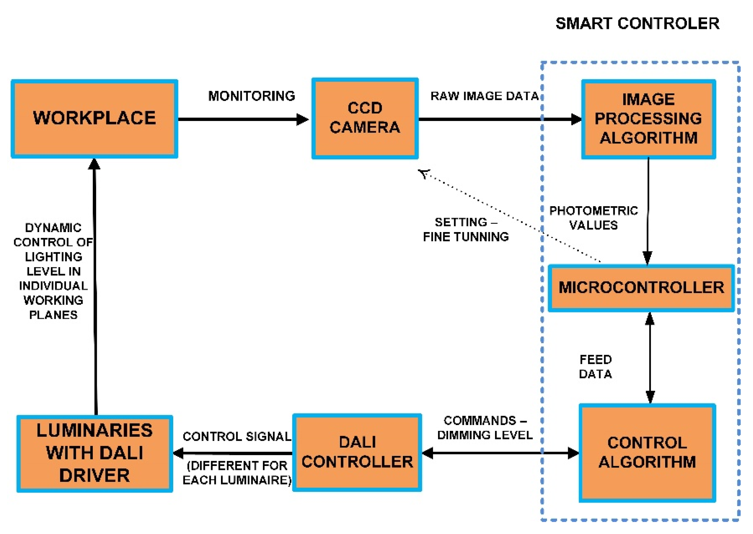
The control system captures an image, performs on board image analysis, transfers the image transformed data for further processing and calculates the appropriate light output levels, which are transmitted to the luminaires through the DALI [
17,
46,
47] controller (
Figure 1). Significant energy savings can be achieved in lighting without sacrificing productivity [
48,
49]. Microcontrollers can contribute towards this direction since they are characterized by low cost and sharp application design and implementation.
The proposed prototype system is based on a 32-bit ARM-based BeagleBone Black microcontroller having an average cost of about 60€, and a high resolution AVT Prosilica GC1290C camera, at a higher cost, however deliberately, in order to obtain high quality photometric measurements. Since the intention is to show the feasibility of such an embedded system, the total cost could be further lowered based on a lower resolution and less expensive IP camera (e.g., the LESHP HW21 1080P 2.0 Megapixel WiFi Color CCD IP Camera at about 55€), and even a cheaper microcontroller (e.g., Raspberry Pi3 at about 30€, NXP/Freescale microcontroller boards at about 40€, or Asus Tinker boards at about 60€, etc.). On the other hand, a stand-alone photosensor (1–10 V signal) costs 20€/luminaire and a DALI photosensor costs 100 €/control daylight zone.
The major drawback of the proposed system is related with privacy issues. The existence of a camera, even for measurements, in an office place may cause discomfort to the occupants. Sarkar et al. [
18] proposed that the camera should be designed in such way so that it does not appear as a conventional one. Furthermore, there is no need to store the image after the generation of the control signal. Motamed et al. [
22] believe that this privacy problems exist only in some cases, as the ‘Y generation’ logged into web-services and social network accounts every day without thinking of privacy issues. Another suggestion is the distortion of moving objects in the camera’s field of view.
This paper is organized as follows: In
Section 2, the design methodology of the system is described. In
Section 3, the implementation of the proposed system is presented.
Section 4 analyzes the software modules developed, the experiments that were conducted and the evaluation of system’s operation. Finally,
Section 5 documents a case study where an algorithm for the identification of dark and light areas luminance in an RGB image is implemented as a means of lighting control.
2. Design of the Proposed Embedded Camera Control System
A low-cost embedded control system was developed in order control a machine vision camera through an Ethernet port. Additionally, the feasibility of using a low-cost microcontroller board and a camera for developing applications in digital lighting control systems was investigated. In this direction, the system development was based upon a microcontroller board that supports such communication mechanism in real time. The system architecture must be flexible and customizable, so as to allow easy adjustment to the desired configuration. The microcontroller must be able to control most aspects of the camera’s operation.
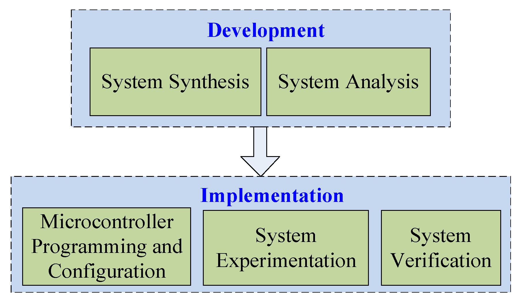
The flow of system development and implementation involves the initial assignment of system units and their specification analysis, the actual programming and configuration steps, and finally real-time experimentations of the application system for functionality verification (
Figure 2).
The proposed camera control system contains most of the essential modules for video capture, video analytics, and host communication. A host PC could be connected for debugging purposes or perform further configurations and processing functions while on commissioning. A general view of the proposed system is given in
Figure 3.
The basic layout consists of a network IP camera, an Ethernet interface controller that provides network access, a memory module that facilitates data exchange between processor and other units, a flash memory controller, other specialized hardware units and ports for communication and programming (through a USB) and finally, a processing unit capable to perform real-time image acquisition and processing. A VGA display could be used to view the streamed video and images output of the camera.
The microcontroller receives input signals from the camera sensor through an Ethernet interface that converts it into acceptable formats (e.g., .raw, .bmp) and stores them in the memory module. The type of image compression plays an important role on hardware system requirements, such as memory units, data rate, external storage units, etc. This is because data must be compressed to a manageable data rate (e.g., streaming 512 × 512 pixel at least at 30 frames/second) that can be routed over the interface to the microcontroller.
BeagleBone microcontroller contains extensive libraries, just like many embedded computers. Initially, basic image processing techniques were incorporated based on additional image processing libraries (e.g., CImg) for general image manipulation and management purposes. Next, for specific image data analysis and management purposes an image-areas identification algorithm was developed (based on MATLAB modules exported into C/C++ units) that identifies the raw image pixel luminance values in order to be applied for the control of a DALI (Digital Addressable Lighting Interface) system. The resulting output could be fed as input to the microcontroller system for further light control on real time. The objective to come up with a system to explore future light control scenarios.
5. Identification of Image Dark and Light Areas in a Computer Laboratory as a Case Study
The application environment for the conducting tests and commissioning was a computer laboratory of a total area of 50 square meters and adequate (for 500 lux at the work plane) number of typical ceiling lights (16 × 2, F36W/840 neutral white) (
Figure 7).
In this application study MATLAB is used to process images captured from a camera on BeagleBone Black board. RGB images coming from BeagleBone Black are processed with a simple regions’ luminance identification algorithm. This image analysis algorithm is a type of image segmentation that isolates objects by converting grayscale images into binary images. In particular, a simple procedure is developed for the identification of the luminance in light and dark areas of an image .img, with a set threshold value thresh, as a MATLAB function findareas(img,thresh). Area recognition is based on features taken from 2D images of the object of interest, e.g., color shade, luminance, and intensity. This method of recognition includes a local class of such features such as color, average gradient, and average gray values of pixels or small regions [
50].
5.1. MATLAB and BeagleBone Black Connection
MATLAB R2015a provides a support package for BeagleBone Black hardware, which can be utilized to access peripheral devices through the BeagleBone Black. This support package allows to acquire data from sensors and imaging devices connected to the BeagleBone Black. Specifically, libraries of MATLAB functions are provided for BeagleBone Black interfaces, such as I2C interface, SPI interface, serial interface, GPIO, and USB webcam. Therefore, using this support package the image processing capabilities of the BeagleBone Black were extended by acquiring data from connected devices, and then analyze and visualize them in MATLAB.
A connection between the MATLAB software and the BeagleBone Black hardware was established through the creation of a beaglebone object using the following beaglebone function:
bbb = beaglebone();
The bbb is a handle to a beaglebone unit. While creating the bbb object, the MATLAB connects to a server running on the BeagleBone Black hardware through TCP/IP. This beaglebone object has a number of methods that allow to execute various commands on BeagleBone Black hardware from within MATLAB.
A connection to a web camera attached to BeagleBone Black hardware is accomplished by the following beaglebone object function:
This creates a camera object. The cam is a handle to this cam object and
img is the RGB image object captured with
snapshot() from web camera in BeagleBone Black hardware. An example of such an image taken is shown in
Figure 7. This image is the raw data that the algorithm uses as input for the image processing and finally the producing of the lighting control signal.
5.2. Image Areas Identification and Processing Algorithm—Experimental Results
The aim is to perform image manipulations that will enable the identification of image regions with maximum or minimum luminous values. In summary, the idea is to calculate the intensity of the red, green, and blue components of the captured image and then threshold the image by eliminating the hue and saturation information while retaining the luminance, in order to identify the specific dark and light areas.
The first step is the extraction of three 2D matrices from the 3D image data corresponding to the red, green, and blue components of the image with the following statements:
r = img(:,:,1);
g = img(:,:,2);
b = img(:,:,3);
Next, we approximate the intensity of the red, green, and blue components:
Red = r − g/2 − b/2;
Green = g − r/2 − b/2;
Blue = b − r/2 − g/2;
Then, the image is threshold with an average thresh value (50%) to find the regions of image that considered to be sufficiently colored accordingly to red, green, and blue.
bwb = Blue > thresh;
bwg = Green > thresh;
bwr= Red > thresh;
In this case study, the identification algorithm was applied to the red (R), green (G), and blue (B) components of an image captured creating a color digital negative effect (see
Figure 8a–c). The R, G, and B components of the image are represented as unit values. That is, the range of the values that any of the color components can take is from 0 to 255.
Next step was to threshold the images by eliminating the hue and saturation information while retaining the luminance, in order to identify the specific dark and light areas. Image thresholding is most effective in images with high levels of contrast (dark and light regions). MATLAB function im2bw(img,level) converts a grayscale image img to a binary image based on a specific threshold level. This threshold value determines which intensities should be set to white and which to black. However, since the input images are not grayscale images, im2bw() converts the input RGB images to grayscale, and then converts these grayscale images to binary by thresholding. As a result, in the output images, all pixels of the input image with luminance greater than the threshold level are replaced with the value 1 (white), while the rest with the value 0 (black). This range [0,1] is relative to the signal levels possible for the image’s class. We do not specify a level argument, therefore, a level value of 0.5 as a midway between black and white, regardless of class.
Images are processed accordingly with the following statements:
bwr_thresholded= im2bw(bwr); figure; imshow(bwr_thresholded); title(’Red thresholded’);
bwg_thresholded= im2bw(bwg); figure; imshow(bwg_thresholded); title(’Green thresholded’);
bwb_thresholded= im2bw(bwb); figure; imshow(bwb_thresholded); title(’Blue thresholded’);
The output images are shown in
Figure 8a–c.
Assuming that the intensity value at position
[x,y] of the image is
img(x,y), the threshold mapping of the identified area is defined by
img_thresholded(x,y) = 255-img(x,y). The change of luminance due to the propagation of light in the lab environment defines the position of the light (white) objects (desks’ surfaces or windows) in each frame. Due to laboratory lighting conditions, some black pixels can appear in white region and the opposite. Although a filter function like
erode could have been applied to remove them. As a result, in the above images the light areas are mapped to light (white), and the dark areas are mapped to dark (black). More details of this technique that has already been applied successfully in the past in objects identification could be found in our previous research work [
51].
The above-mentioned are quite evident particularly in
Figure 9a,b, based on the results obtained during the experiments in the laboratory. There, the (light and dark) areas of interest can be easily identified using just these thresholding features. As a result, the intensity values at the light areas were estimated at a high brightness value above 250. Such light regions constitute the desks’ surfaces that reflect the lighting (at coordinates (110,300), (300,400)), and the windows region that allows the sunlight to pass through into the laboratory (at coordinates (350,700), (100,250)).
5.3. Control Unit Power Consumption—Experimental Results
The control system is based on a low-cost, low-powered (5V), portable, and stand-alone powerful microcontroller board, that is being used for embedded low-powered control applications, due to its computing power in regard to its price, and its ease of use with peripheral equipment. A high-resolution Ethernet CCD camera is being used as the images input source, in order to obtain high quality photometric measurements during the experimentation. Therefore, a lower resolution, less expensive, and low energy consumption CCD or CMOS camera could also be used, either wireless or through Ethernet, or attached to the microcontroller in a USB port, or better on a camera cape that runs on low-powered 3.3 V or 5 V from the board’s expansion connectors. In this case of BeagleBone with a 1.3 megapixel, 1/6-inch Aptina MT9M114 HD sensor (720p, 30fps) attached to the board through the low-powered cape, measurements have shown that the system’s (microcontroller plus camera) overall power consumption remains low.
A conventional DALI photosensor and the developed system (camera and microcontroller) were tested (
Figure 10). The measurements took place in the Photometry Laboratory of the National Technical University of Athens. The ambient temperature was maintained constant at 26 °C and input voltage at 230 V AC, 50 Hz through the voltage stabilizer for all tested conditions. A single-phase power analyzer was used for the measurement of active, reactive and apparent power.
Table 1 presents the electrical results of the tested systems. Each of the tested equipment can control the existing lighting system of the computer laboratory (16 luminaires x 2 lamps, F36W/840 and electronic ballast, resulting in 1152 W) or an upgraded one with LED luminaires (16 luminaires 40 W each, resulting in 640 W). Energy savings due to daylight harvesting correspond to more than 50% of the initial power consumption of the lighting system [
34,
37]. Moreover, the daylight factor of the room is above 2.6. Thus, for Athens daylight levels exceed 500 lx for more than 50% of the operating hours [
52].
Table 2 presents the total power consumption of the lighting system including lighting control for each scenario. Although the proposed control system with the camera consumes more power than a conventional photosensor, differences in energy savings are negligible (0.12% in a lighting system using tubular fluorescent lamps and 0.21% in a LED lighting system).
5.4. Control of the DALI Digital Lighting System
By measuring the luminance in these areas, a control system can accordingly increase or decrease digitally the dimming of individual DALI ballasts for each of these areas. Appropriate management would lead to the desired lighting environment and ensure proper energy consumption. For this purpose, a typical control scheme is implemented, where the BeagleBone microcontroller acts as the master device for sending and receiving instructions to/from the DALI driver unit (slave), through an isolation circuit of optocouplers, powered by the microcontroller’s 3.3 V power supply. The control system interprets the image luminance data of the identified dark and light areas produced by the function findareas(img,thresh), and accordingly, based on the specified coordinates, sends appropriately formatted DALI commands (that conform to IEC-60929 DALI protocol standard) to the corresponding DALI ballast’s driver, for commissioning and dimming purposes.
DALI ballasts are capable of providing 256 levels of brightness, which follow a logarithmic dimming curve. Taking that into consideration, the microcontroller’s control software transforms image-areas luminance values into appropriate control signals that drive ballast’s dimming operations. For instance, in the case of the laboratory experimental study, the light’s intensity is varied accordingly based on the identified light areas luminance values—e.g., the desks’ surface area defined within the coordinates (110,300) and (300,400) has an average high brightness value of 255. This is computed as follows. Having already identified the light areas, as described in
Section 5.2 above, e.g., in green colored region threshold with
bwg_thresholded= im2bw(bwg);, and extracted the individual RGB color components, e.g. for green coloured region with
g = img(:,:,1);, then the intensity value at an estimate center of this area is calculated with the following:
[x, y] = find(bwg);
xx = max(1, round(mean(x)) − 5):min(round(mean(x)) + 5, size(area, 1));
yy = max(1, round(mean(y)) −5 ):min(round(mean(y)) + 5, size(area, 2));
Then, the actual brightness value at this center point is returned with the following:
For the center point of the example surface area defined within the coordinates (110,300) and (300,400), the brightness value returned was of 255. Actually, the intensity of this area at this representative point takes in account the individual weights of the red, green and blue components. A Bayer filter—commonly used in color CCD sensors—filters the light intensity in RGB spectral regions. The spectral response curve of the green pattern corresponds to the photopic human eye sensitivity V(λ), which means that luminance values can be extracted using only the green component [
36]. Thus, for the light area in the green colored region threshold based on the following:
img(:,:,1) = uint8(r + bwgv);.
img(:,:,2) = uint8(g − bwgv);
img(:,:,3) = uint8(b − bwgv);
Having estimated this brightness value (e.g., for this test surface area at a value of 255) now the actual 8-bit DALI input is formulated accordingly, as explained below, to a lower approximate input value, e.g., of 202. In this case, in order to lower energy consumption, the light’s intensity of the corresponding at these coordinates, the luminaire is decreased by about 25%—e.g., at a value of 202—with a direct level command for an arc value of 202, generated for this purpose simply as 254202. The format of this forward command is a decimal representation of the ballast’s address (254) and arc’s value data bytes (202). Based on the DALI communication protocol, such a forward frame command consists of 19 bits (1 start bit, 1 address byte, 1 data byte, 2 stop bits), namely in binary 1111111101111001011.
Finally, the microcontroller sends this command frame over a two-wire voltage interface, by means of asynchronous, half-duplex, serial protocol, as appropriate signals to the ballast’s DALI driver, with a fixed data transfer rate of 1200 bit/s. In fact, the signal values are inverted due to the optocouplers’ signal level inversion. At this control interface, a voltage between 9.5 V and 22.5 V is considered a physical high signal (usually 16 V), whereas a voltage in the ±6.5 V interval is taken as a physical low signal. Overall, this direct level command is sent to the DALI driver as a bi-phase Manchester encoded packet.
The control software of the DALI driver is implemented as a kernel driver module loaded into the microcontroller’s Linux kernel. This kernel module facilitates the communication of the BeagleBone microcontroller with any DALI controller, based on the DALI protocol standard. In this way, any application can call driver’s functions to write and read from any DALI device.
Part of the above MATLAB function findareas(img,thresh) supports the generation of C code using MATLAB Coder for a generic MATLAB host computer target platform. Further on, a simulation model of the above algorithm could be designed in Simulink, then generate code (ANSI/ISO C/C++) using Embedded Coder, and run the executable as a standalone application on BeagleBone Black unit.
Overall, the proposed system is a low-cost prototype of a digital lighting control system, applied in the real-time acquisition of surface area images, and light data extraction and processing, for efficient dimming control purposes. This is one of the innovative aspects of this research work, which contributes to lower energy consumption.
6. Conclusions
The building sector today is considered as the largest single contributor to world energy consumption. Therefore, one of the major objectives of this research work was to increase the energy efficiency of lighting control systems applied in typical domestic and industrial building structures.
This paper proposes a microcontroller-based method of designing a camera controller. An initial design of an embedded microcontroller camera control system was developed and tested upon real-time conditions. The overall control system is capable of acquiring real image data and realize efficient image manipulation and processing as captured through Ethernet for digital dimming control purposes. For this purpose, a novel algorithm was developed using MATLAB that enables the identification of dark and light areas and performs the calculation of their luminance values. Furthermore, the microcontroller uses these measurements to apply adequate dimming levels, in order to control the illumination of several working areas within the application building structure, e.g., a room or a laboratory. The validity of the proposed system was evaluated through actual experiments on live camera captured image data.
The proposed image-based digital lighting embedded control system demonstrates the ability to perform DALI digital dimming operations, based on image-areas luminance values identification. Although it is a prototype, the proposed control system and software offers specific advantages compared to previous studies and approaches that were examined at the introduction of this paper. The advantages and novelties of the proposed system can be summarized into the following:
It is a flexible control system, based on a low-cost, low-powered ARM-based BeagleBone Black microcontroller and high-resolution CCD GigE IP camera controlled via Ethernet/internet (although a low-cost, low-energy consumption CMOS camera could have also been used).
Simple but efficient image segmentation algorithm for illuminance estimation of specific ‘light areas’ (in contrast to the ‘dark areas’) and higher accuracy in the control of lighting ballasts. Both features lead to higher energy savings.
Rapid application development and ease of modification based on high-level coding language and the use of open source image libraries such as C++ CImg, which could also enable efficient commissioning in terms of time and cost, or provide other maintenance and control benefits to the individual user.
Although the installed power is slightly larger for the microcontroller and camera control system compared with a typical photosensor, the overall energy performance is almost equivalent and the differences in energy consumption are negligible.
The outcome of this research is a flexible, low-cost embedded system prototype, which builds upon a microcontroller with a CCD camera, capable to perform image processing analytics in purpose of real-time lighting control. Commercial controllers still do not possess the required flexibility and intelligence required to automatically identify and efficiently adjust the luminance of specific areas. This prototype represents an added value towards this goal. Future work could provide a more compact version, with improved commissioning and specific other features, which could be fabricated for commercialization and other exploitation purposes.

 ,
, 


