Circularly Polarized Array with Enhanced Isolation Using Magnetic Metamaterials


1
Institute of Electronic Engineering, China Academy of Engineering Physics, Mianyang 621999, China
2
School of Electronics & Information Engineering, Xi’an Jiaotong University, Xi’an 710049, China
*
Author to whom correspondence should be addressed.
Electronics 2019, 8(11), 1356; https://doi.org/10.3390/electronics8111356
Submission received: 11 October 2019
/
Revised: 7 November 2019
/
Accepted: 12 November 2019
/
Published: 15 November 2019
(This article belongs to the Section Microwave and Wireless Communications)
Abstract
:This article proposes a 2 × 2 circularly polarized array with enhanced isolation that could be used in the adaptive anti-jamming system for China’s Beidou Navigation Satellite System (BDS), and a compact dual-band microstrip antenna for GPS and GLONASS is designed at the center part of the array for multiple modes operation. The substrate integrated split ring resonators with negative effective permeability are used as the magnetic metamaterials. Four groups of the magnetic metamaterials are placed between the BDS antenna elements, which could constrain the EM filed in the area of the active element, and then significantly reduce the mutual coupling among the elements. The results tell that the isolation among the BDS elements are improved by more than 10 dB, and the performance of radiation patterns and the axial ratio of each BDS elements are also apparently improved compared to the array without magnetic metamaterials.
1. Introduction
China’s Beidou Navigation Satellite System (BDS) is becoming more widely used on vehicles, boats, and aircraft in China. Due to the relatively weak signal levels, the terminal devices are very sensitive to the jamming which may cause the receivers blocked and functions abnormally. Then, adaptive anti-jamming antenna arrays are designed to settle this problem [1,2,3], which can adaptively place the nulls of the radiation pattern towards the direction of the jamming signals. The number of nulls is determined by the number of elements in the array. The 2 × 2 array is often used to generate three nulls pointing to different directions at the same time.
The capability of anti-jamming is determined by many aspects, and the isolation among each channel plays an important role, which could directly affect nulling depth of the radiation pattern [4,5,6]. However, in the antenna array, it is difficult to achieve high isolation, due to the compact structure and the mutual coupling resulting from surface wave and spatial propagation among the elements. Some previous researches have been done to reduce the mutual coupling between antennas. The authors of [7] propose a simple resonant slot on the ground between the closely spaced microstrip MIMO antennas. In [8], a compact MIMO antenna with T-shaped slots loaded ground is presented which achieves high isolation in ultrawide band. As verified in [9], the metasurface can also be applied in the closely arranged patch antenna array by creating an indirect coupling path with phase delay to counteract the direct near field coupling. According to the mechanism of isolation enhancement in the references mentioned above, they are not suitable for elements spaced half wavelength in arrays. For the arrays, the slotted meander-line resonator is used to block the surface current of two patch antennas coupled along H-plane [10], but it only focuses on the linear polarization. The electromagnetic band-gap (EBG) structure [11] is investigated in the circularly polarized array, although it needs a relatively large space. Magnetic metamaterials with negative permeability have been proved as an effective way for isolation enhancement. In [12], the substrate integrated split ring resonators (SI-SRRs) are designed with high permeability and negative permeability to simultaneously guide and block the surface wave. Only linear polarization (paralleled to the SRR) is investigated, and the mutual coupling reduction reaches 10dB, whereas the cross-polarization is not investigated, and the performance and application of SI-SRR needs further exploration. In [13], the authors propose an isolation enhanced circularly polarized array with miniaturized GPS elements. The isolation structures are composed of several broadside coupled SRRs (BC-SRRs) and provide more than 10 dB mutual coupling reduction. However, because of the vertical connection of the isolation structures and the aperture, the proposed structures are not suitable for practical applications with strong vibration circumstance (e.g., the aircraft, missiles, or other high speed vehicles) and are difficult to fabricate.
In this article, a 2 × 2 circularly polarized array is designed, and magnetic metamaterial is integrated in the same substrate with the radiation elements to reduce the surface wave coupling, which takes the dominating proportion of the mutual coupling. In addition, to receive the GPS and GLONASS signals at the same time without adaptive nulling, a dual-band circularly polarized microstrip antenna is added in the array.
2. Antenna Design
2.1. BDS and GPS/GLONASS Antenna Element and Array
To keep the low profile of the array, a microstrip patch antenna is used as the radiation element. The geometry of the BDS antenna is depicted in Figure 1a. Four round disks with different radius are placed on the corners of the square patch to generate two orthogonal modes, which then result in circular polarization performance [14]. A ring gap is added around the feeding structure, which brings capacitance to partially neutralize the inductance caused by the feeding pin, increasing the impedance bandwidth of the antenna. The geometry of the GPS/GLONASS antenna is depicted in Figure 1b. The strip-line Wilkinson power divider with equal amplitude and 90 phase difference is designed to generate wideband circular polarization of the radiation patch. This antenna is composed of three layers of substrate and the ground plane is between the radiation patch and the strip-line.
The array with four BDS antennas of 2 × 2 arrangement and one GPS/GLONASS antenna with 45 rotation at the center is illustrated in Figure 1c. To achieve better circular polarization performance, the four BDS radiation elements are rotated 90 clockwise in sequence. The aperture of the array is 200 mm × 200 mm, which is commonly used in the adaptive anti-jamming antenna system. Whereas in the simulation, we place the BDS radiation element at the center of a 100 mm × 100 mm ground plane at first. After we obtain an optimal result, we place the element at the center of a quarter of the 200 mm × 200 mm aperture. The radiation patterns and axial ratio performance of the BDS antenna would be influenced by the asymmetric ground plane, so the values of the geometry parameters are slightly adjusted and optimized as listed in Table 1, and the parameters of the GPS/GLONASS antenna are listed in Table 2. The substrates used in this antenna array are listed in Table 3.
The simulated results of the BDS antenna are depicted in Figure 2. The reflection coefficient remains below −10 dB from 1.245 to 1.280 GHz, wider than 1.268 GHz ± 10 MHz, which is the working band of the BDS antenna, and the axial ratio is 3.2 dB at the center frequency. The isolation is −15.5 dB between the adjacent elements and −16.5 dB between the diagonal elements. The radiation patterns for the antenna in the array shows that the cross-polarization rises, owing to the mutual coupling.
As shown in Figure 3, the GPS/GLONASS dual-band antenna has good radiation patterns and axial ratio performances, and the reflection coefficient is lower than −20 dB in both working bands, 1575.42 MHz ± 2 MHz and 1602 MHz ± 4 MHz, respectively. The gains reach 5 dBi for the two bands.
2.2. Unit Cell of the Magnetic Metamaterial
The aforementioned simulated results in Figure 2 show that the mutual coupling between the BDS elements deteriorates the axial ratio bandwidth and cross-polarization level, and, more importantly, when used in the anti-jamming system, the performance of nulling depth would be obviously influenced by this mutual coupling. Therefore, the means are required to solve this problem.
To keep the low profile of the array and for easy fabrication, it is better to integrate the isolation structure on the same substrate with radiation elements. The Substrate Integrated Split Ring Resonator (SI-SRR) is adopted in this design. The unit cell is composed of two short paralleled lines, two shorting pins to the ground, and the connecting microstrip lines. The unit cell and its equivalent LC circuit is shown in Figure 4a, and its resonating frequency is , where L and C are the lumped inductance and capacitance representing the distributed reactance of the structure, respectively.
The metamaterials with artificially designed permittivity and permeability are studied in [15,16,17,18], and the effective permeability of the SRR can be expressed as
where F is the filling factor of the metallic pattern in the unit, is the working angular frequency, is the resonating angular frequency of the equivalent circuit for the SRR, and is the dissipation factor. From Equation (1), can be artificially designed, and high permeability or negative permeability can be obtained near the resonating frequency of the SRR.
By simulation with suspending microstrip method in Ansys HFSS, the S parameters are obtained and shown in Figure 4b. We can see a transmission null around the operating frequency, which indicates that the structure stops the wave from propagating along the interface. The effective permeability of the structure can be calculated from the S parameters according to the method introduced in [19,20], and Figure 4c shows the calculation results of the effective permeability. The real part of the effective permeability is negative around the operating frequency, and Table 4 gives the optimized geometric parameters of the SI-SRR.
2.3. Array with Magnetic Metamaterials
At first, when the GPS/GLONASS antenna is not added in the aperture, only one SI-SRR is used between the elements, and the isolation is enhanced by ~3 dB between the adjacent elements and 1.5 dB between the diagonal elements. The resonance is not obvious on the SRR. Then, the influence of the isolation caused by the variation of several parameters is investigated by simulation with Ansys HFSS, including N (the number of the SRRs), S (the distance from the aperture center to the edge of SRRs), and (the distance between two SRRs in one group). When two SRRs are used, the isolation is enhanced by 7 dB and 6 dB for the adjacent elements and diagonal elements, respectively. When three SRRs are used, the isolation is enhanced significantly. Though the isolation may be higher with more SRRs, considering the space needed for four or even more SRRs, we believe that “three-SRRs” is a good choice in this design. At last, four groups of isolation structures are added in the array. Each group is composed of three SI-SRRs and placed between adjacent elements. The array with isolation structures is shown in Figure 5. The values of S and also affect the isolation among the elements. The parameters are optimized as S = 46.6 mm and = 4.7 mm. We add the GPS/GLONASS antenna to the array for multiple mode operation while the isolation between the BDS antennas almost remains unchanged.
The full wave simulation is then carried out with Ansys HFSS, and good results are obtained. The proposed isolation enhanced array is then fabricated with PCB process. The measured results will be shown and discussed in the next section.
3. Results and Discussion
The measured results of the GPS/GLONASS dual-band antenna in the array are depicted in Figure 6. The (Figure 6a) reflection coefficient is approximately −15 dB and −30 dB at two band, respectively. The (Figure 6b) axial ratio is below 3 dB from 1.563 GHz to 1.606 GHz, and the (Figure 6c) gain is higher than 3.7 dB from 1.575 GHz to 1.60 GHz. The normalized radiation patterns for GPS band and GLONASS band are shown in Figure 6d,e, and the half power beam width is ~100 for both bands.
The measured results of S parameters for the BDS antenna are shown in Figure 7a. The −10 dB bandwidth of reflection coefficient is from 1.255 to 1.285 GHz, covering the working band of the BDS. The isolation between the elements is enhanced significantly, reaching S21 = −42.1 dB, S31 = −28.1 dB, S41 = −32.5 dB, and S23 = −28.9 dB. For comparison, the installations between the elements without magnetic metamaterials (MMs) are also plotted in the figure. The isolations are enhanced by more than 10 dB. Figure 7b shows that the axial ratios are ~1 dB and the gains are higher than 3.7 dBi at the center frequency.
To illustrate the radiation patterns of the BDS antennas, we use the coordinate axes defined in Figure 5. Due to the rotation of each patch, different cutting planes, comprising the normal axis of the aperture and the connecting line starting from the patch center to the feeding point, i.e., plane XOZ for 1# and 4#, plane YOZ for 2# and 3#, are used to illustrate the radiation patterns. From the radiation patterns shown in Figure 8, we can see that the cross-polarization (left hand circular polarization (LHCP)) obviously decreases compared with the array without isolation structures, whereas the right-hand circular polarization (RHCP) remains unchanged.
The surface current distributions on the aperture of the proposed array with and without the isolation structures are illustrated in Figure 9. Element 1# is excited while the other three elements are terminated. When no magnetic metamaterials are loaded, the mutual coupling is strong due to the surface wave coupling along the interface. When loaded with the magnetic metamaterials, the surface current is mainly confined to the area of the active elements, and a strong resonance can be found on the magnetic metamaterials, which blocks the propagation of the surface wave and then reduce the mutual coupling.
4. Improvement of Anti-Jamming Ability
The power inversion algorithm is adopted for adaptive nulling. When the proposed array is used in the anti-jamming antenna system, especially during its adaptive nulling process, we cannot measure the radiation patterns with nulls in the far-field microwave anechoic chamber. Therefore, we use an equivalent method to describe the performance of nulling ability.
The average power level on the ground of BDS is approximately −125 dBm, and the background noise power level is approximately −100 dBm, so the average signal–noise ratio is −25 dB. When the interference to signal–noise ratio is 75 dB, which indicates that the interference power level is −50 dBm on the antenna aperture, the BDS receiver needs to function well.
Normally, for the receivers, the threshold of signal–interference plus noise ratio (SINR) should be lower than −25 dB. In the simulation, the range of threshold is set from −45 dB to −30 dB. When the output SINR of the receiver is higher than the threshold, we consider that the receiver functions well. We use Available Angle Region Percentage (AARP) to describe the ability of anti-jamming, the following figures show the simulation results with Single Tone Continuous Wave (STCW) jammer and Wide Band (20 MHz) Continuous Wave (WBCW) jammer.
From Figure 10, we can draw the following conclusions.
- The AARP decreases with the increase of SINR threshold.
- The AARP decreases with the increase of the number of jammers.
- The AARP is lower with the BWCW jammer than that with the STCW jammer.
Comparing the influence caused by the isolation structures, we can see that:
- With the STCW jammer, where the ability margin of the system is quite sufficient, the AARPs for the system with and without the isolation structures have no big difference.
- With the WBCW jammer, where the ability margin of the system is not sufficient, the AARP for the system with isolation structures is obviously higher than that without isolation structures.
In summary, the isolation structures reduce the mutual coupling, resulting in better anti-jamming abilities or nulling depth, especially for wideband jammer.
5. Conclusions
In this article, a 2 × 2 circularly polarized array for adaptive anti-jamming antenna used for BDS is proposed, and a compact dual-band antenna for GPS and GLONASS is designed simultaneously. Substrate integrated split ring resonators are utilized as the magnetic metamaterials to reduce the mutual coupling among the BDS antennas, aiming to have a better performance in adaptive nulling. Four groups of isolation structures are placed between the adjacent elements. Each group is composed of three SI-SRRs, which are designed with negative effective permeability to block the surface wave coupling among the radiation elements, and then the mutual coupling reduction of circular polarization is investigated. The measured results tell that the isolations are enhanced by more than 10 dB in the working band, whereas the cross-polarization level and axial ratio of the elements decrease obviously. The GPS/GLONASS antenna at the center is barely influenced by the BDS antennas and performs well. As the SI-SRRs are designed on the same substrate with the radiation elements, the proposed antenna array is easy for fabrication and has low profile, which could be a good choice for the similar applications, especially for some certain platforms with strong vibration because of its firm structure. At last, the ability of adaptive anti-jamming is investigated by simulation with the mutual coupling of the arrays with and without isolation structures, which indicates that the isolation structures improve the performance of the nulling ability.
Author Contributions
Conceptualization, B.L.; Data curation, B.L. and J.S.; Formal analysis, B.L. and J.S.; Funding acquisition, J.L.; Investigation, B.L. and J.S.; Methodology, B.L. and J.L.; Project administration, Z.Y.; Resources, Z.Y. and A.Z.; Supervision, C.Y. and Z.Y.; Validation, J.S.; Visualization, B.L.; Writing—original draft, B.L.; Writing—review & editing, B.L. and J.L.
Funding
This work was supported in part by the National Natural Science Foundation of China under Grant No. 61801369 and the China Postdoctoral Science Foundation under Grant No. 2018M631161
Conflicts of Interest
The authors declare no conflicts of interest.
Abbreviations
The following abbreviations are used in this manuscript.
| BDS | (China) Beidou Navigation Satellite System |
| GPS | (America) Global Positioning System |
| GLONASS | (Russia) Global Navigation Satellite System |
| SI-SRR | Substrate Integrated Split Ring Resonator |
| MM | Magnetic Metamaterial |
| SINR | Signal to Interference plus Noise Ratio |
| AARP | Available Angle Region percentage |
| STCW | Single Tone Continuous Wave |
| BWCW | Wide Band Continuous Wave |
References
- Fante, R.L.; Blanchard, J.; Correia, J.; Nissen, T.C. Cancellation of jammers and jammer multipath in a GPS receiver. In Proceedings of the IEEE 1998 Position Location and Navigation Symposium, Palm Springs, CA, USA, 20–23 April 1998; pp. 622–625. [Google Scholar]
- Falcone, K.; Dimos, G.; Yang, C.; Nima, F.; Wolf, S.; Yam, D.; Weinfeldt, J.; Olson, P. Small Affordable Anti-Jam GPS Antenna (SAAGA) Development. In Proceedings of the International Technical Meeting of the Satellite Division of the Institute of Navigation, Nashville, TN, USA, 14–17 September 1999; pp. 1149–1156. [Google Scholar]
- Reynolds, D.; Brown, A.; Reynolds, A. Miniaturized GPS Antenna Array Technology and Predicted Anti-Jam Performance. In Proceedings of the 12th International Technical Meeting of the Satellite Division of the Institute of Navigation, ION GPS, Nashville, TN, USA, 14–17 September 1999; pp. 777–786. [Google Scholar]
- Ali, M.A.; Wahid, P. Effect of mutual coupling in adaptive arrays. Microw. Opt. Technol. Lett. 2002, 35, 270–274. [Google Scholar] [CrossRef]
- Iskander, M.A. Mitigation of mutual coupling effects in microstrip adaptive arrays for portable devices. In Proceedings of the 28th National Radio Science Conference (NRSC), Cairo, Egypt, 26–28 April 2011; pp. 1–10. [Google Scholar]
- Deger, S.; Saka, B. Effect of Mutual Coupling on the Performance of Adaptive Arrays. In Proceedings of the IEEE 14th Signal Processing and Communications Applications, Antalya, Turkey, 17–19 April 2006; pp. 1–4. [Google Scholar]
- OuYang, J.; Yang, F.; Wang, Z.M. Reducing Mutual Coupling of Closely Spaced Microstrip MIMO Antennas for WLAN Application. IEEE Antennas Wirel. Propag. Lett. 2011, 10, 310–313. [Google Scholar] [CrossRef]
- Luo, C.; Hong, J.; Zhong, L. Isolation Enhancement of a Very Compact UWB-MIMO Slot Antenna with Two Defected Ground Structures. IEEE Antennas Wirel. Propag. Lett. 2015, 14, 1766–1769. [Google Scholar] [CrossRef]
- Panda, P.K.; Ghosh, D. Isolation Enhancement of Patch Antennas using Metamaterial Superstrate. In Proceedings of the IEEE International Symposium on Antennas and Propagation & USNC/URSI National Radio Science Meeting, San Diego, CA, USA, 9–14 July 2017; pp. 1739–1740. [Google Scholar]
- Alsath, M.G.; Kanagasabai, M.; Balasubramanian, B. Implementation of Slotted Meander-Line Resonators for Isolation Enhancement in Microstrip Patch Antenna Arrays. IEEE Antennas Wirel. Propag. Lett. 2013, 12, 15–18. [Google Scholar] [CrossRef]
- Expósito-Domínguez, G.; Fernandez-Gonzalez, J.M.; Padilla, P.; Sierra-Castaner, M. Mutual Coupling Reduction Using EBG in Steering Antennas. IEEE Antennas Wirel. Propag. Lett. 2012, 11, 1265–1268. [Google Scholar] [CrossRef]
- Liu, Z.; Wang, J.; Qu, S.; Zhang, J.; Ma, H.; Xu, Z.; Zhang, A. Enhancing isolation of antenna arrays by simultaneously blocking and guiding magnetic field lines using magnetic metamaterials. Appl. Phys. Lett. 2016, 109, 153505. [Google Scholar] [CrossRef]
- Gheethan, A.; Herzig, P.A.; Mumcu, G. Compact 2 × 2 coupled double loop GPS antenna array loaded with broadside coupled split ring resonators. IEEE Trans. Antennas Propag. 2013, 61, 3000–3008. [Google Scholar] [CrossRef]
- Anjani, Y.S.; Alphones, A. A Wide-Beam Circularly Polarized Asymmetric-Microstrip Antenna. IEEE Trans. Antennas Propag. 2015, 63, 3764–3768. [Google Scholar]
- Pendry, J.B.; Holden, A.J.; Robbins, D.J.; Stewart, W.J. Magnetism from conductors and enhanced nonlinear phenomena. IEEE Trans. Microw. Theory Tech. 1999, 47, 2075–2084. [Google Scholar] [CrossRef]
- O’Brien, S.; Pendry, J.B. Photonic band-gap effects and magnetic activity in dielectric composites. J. Phys. Condens. Matter 2002, 14, 4035–4044. [Google Scholar] [CrossRef]
- Ishikawa, A.; Tanaka, T.; Kawata, S. Negative magnetic permeability in the visible light region. Phys. Rev. Lett. 2006, 95, 237401. [Google Scholar] [CrossRef] [PubMed]
- Ramakrishna, S.A. Physics of negative refractive index materials. Rep. Prog. Phys. 2005, 68, 449–521. [Google Scholar] [CrossRef]
- Smith, D.R.; Schultz, S.; Markoš, P.; Soukoulis, C.M. Determination of effective permittivity and permeability of metamaterials from reflection and transmission coefficients. Phys. Rev. B 2001, 65, 195104. [Google Scholar] [CrossRef]
- Smith, D.R.; Vier, D.C.; Koschny, T.; Soukoulis, C.M. Electromagnetic parameters retrieval from inhomogeneous metamaterials. Phys. Rev. E Stat. Nonlinear Soft Matter Phys. 2005, 71, 36617. [Google Scholar] [CrossRef] [PubMed] [Green Version]
Figure 1.
The top and side view of the (a) Beidou Navigation Satellite System (BDS), (b) GPS/GLONASS antenna, and (c) top view of the array with poor isolation.
Figure 1.
The top and side view of the (a) Beidou Navigation Satellite System (BDS), (b) GPS/GLONASS antenna, and (c) top view of the array with poor isolation.
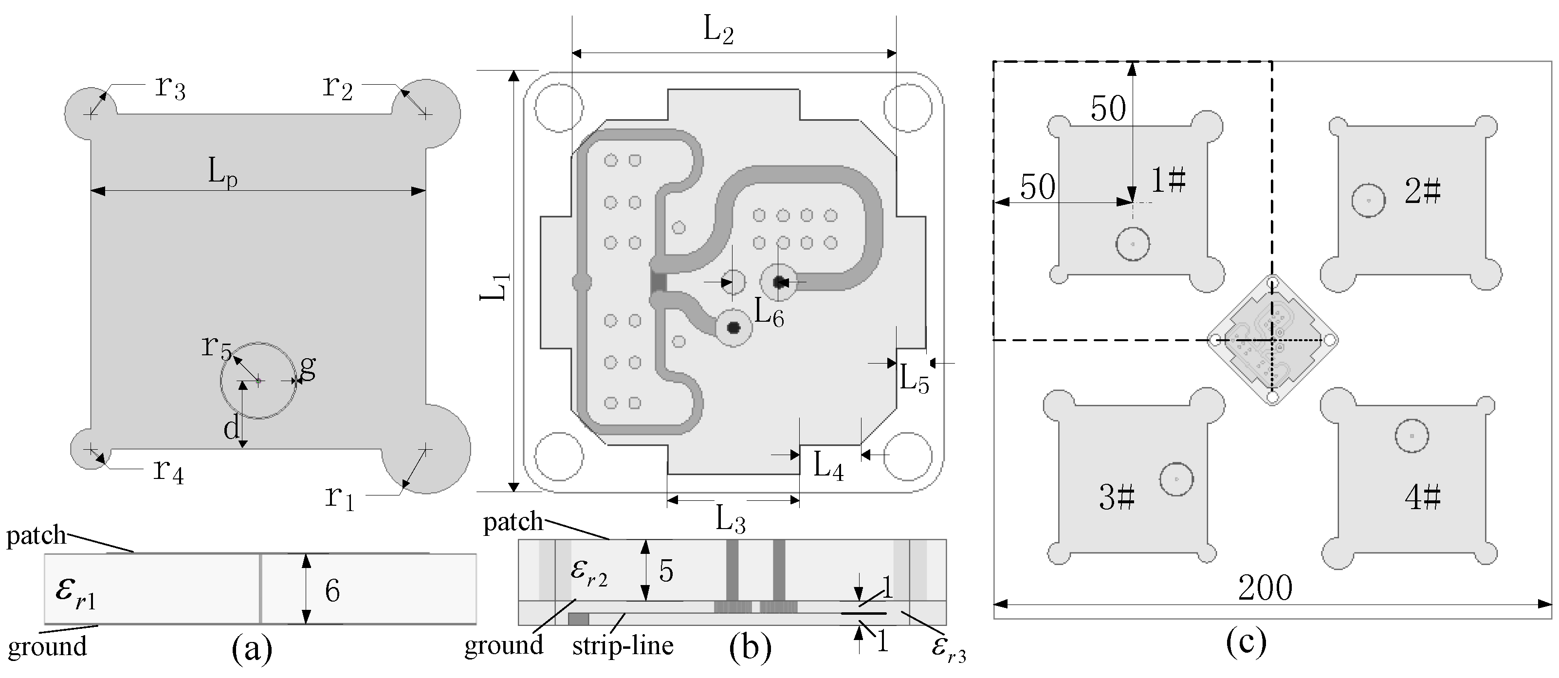
Figure 2.
The (a) S parameters and axial ratio and (b) radiation patterns of the BDS antenna without magnetic metamaterials.
Figure 2.
The (a) S parameters and axial ratio and (b) radiation patterns of the BDS antenna without magnetic metamaterials.
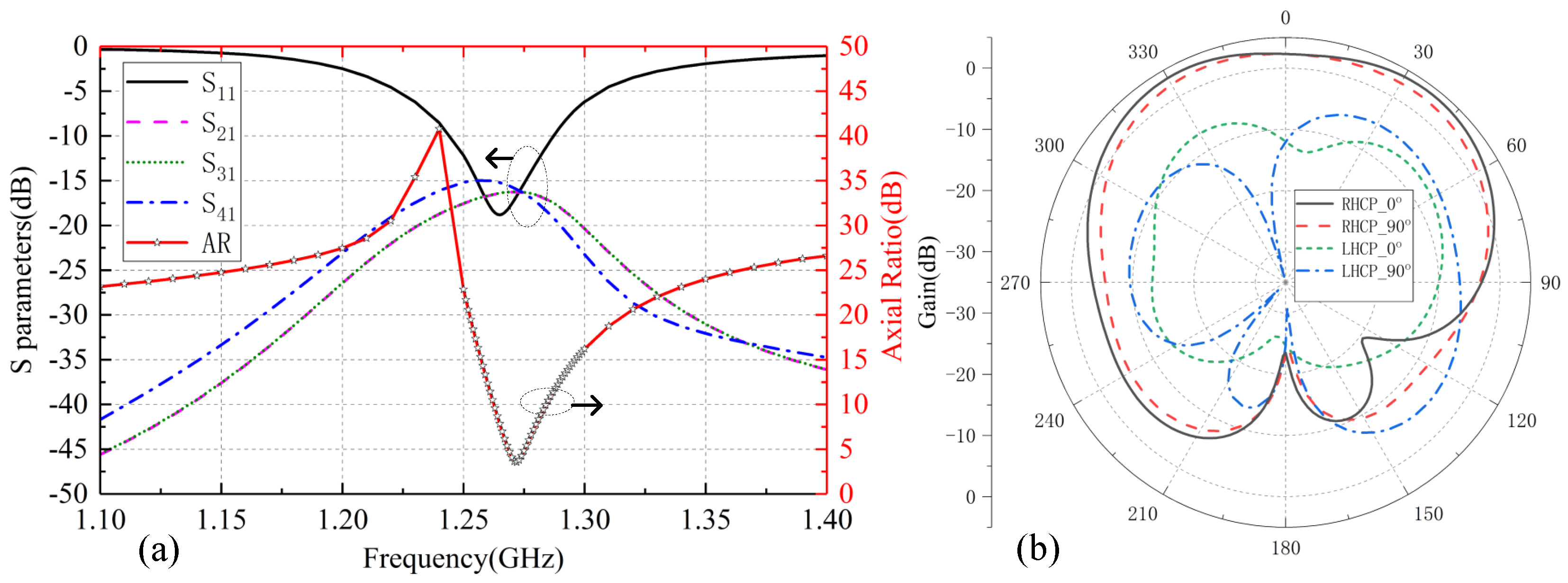
Figure 3.
The (a) S parameters and axial ratio and (b) radiation patterns of the GPS/GLONASS antenna in the array.
Figure 3.
The (a) S parameters and axial ratio and (b) radiation patterns of the GPS/GLONASS antenna in the array.

Figure 4.
The (a) geometry of the Substrate Integrated Split Ring Resonator (SI-SRR) and its equivalent circuit, (b) simulated S parameters of the SI-SRR, and (c) calculated effective permeability of the SI-SRR.
Figure 4.
The (a) geometry of the Substrate Integrated Split Ring Resonator (SI-SRR) and its equivalent circuit, (b) simulated S parameters of the SI-SRR, and (c) calculated effective permeability of the SI-SRR.

Figure 5.
The array with the isolation structures (a) simulation model and (b) fabricated array.
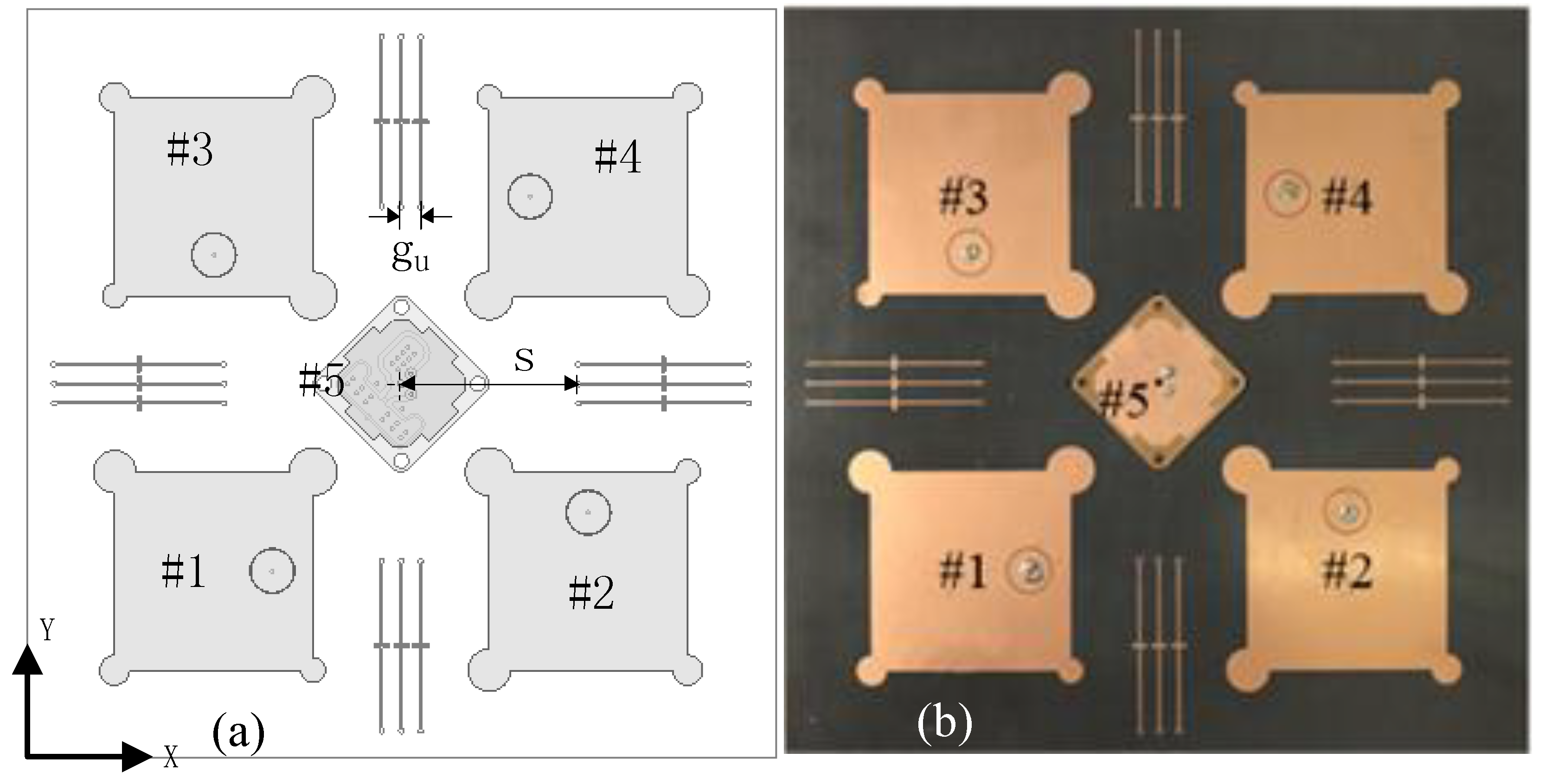
Figure 6.
The measured results of the GPS/GLONASS dual-band antenna: (a) reflection coefficient, (b) axial ratio, (c) gain, normalized radiation patterns of (d) GPS band, and (e) GLONASS band.
Figure 6.
The measured results of the GPS/GLONASS dual-band antenna: (a) reflection coefficient, (b) axial ratio, (c) gain, normalized radiation patterns of (d) GPS band, and (e) GLONASS band.

Figure 7.
The measured (a) S parameters, (b) Axial ratio and gain of each BDS antenna with magnetic metamaterials.
Figure 7.
The measured (a) S parameters, (b) Axial ratio and gain of each BDS antenna with magnetic metamaterials.

Figure 8.
The measured normalized radiation patterns of each BDS antenna in the isolation enhanced array.
Figure 8.
The measured normalized radiation patterns of each BDS antenna in the isolation enhanced array.

Figure 9.
Surface current distribution of the array (a) with and (b) without isolation strutures.

Figure 10.
The AARP (representing anti-jamming abilities) varies with different number of Single Tone Continuous Wave (STCW) jammers—(a) one, (b) two, (c) three, and Wide Band Continuous Wave (WBCW) jammers—(d) one, (e) two, (f) three.
Figure 10.
The AARP (representing anti-jamming abilities) varies with different number of Single Tone Continuous Wave (STCW) jammers—(a) one, (b) two, (c) three, and Wide Band Continuous Wave (WBCW) jammers—(d) one, (e) two, (f) three.


Table 1.
The parameters of the BDS antenna element.
| Paramenters | d | g | ||||||
| Value(mm) | 52.3 | 10.85 | 0.2 | 6.4 | 5.7 | 4 | 3.3 | 5.8 |
Table 2.
The parameters of the GPS/GLONASS antenna.
| Paramenters | ||||||
| Value(mm) | 35 | 27 | 11 | 5.04 | 2.5 | 3.8 |
Table 3.
The parameters of the substrates used in the array.
| Substrate | Thickness (mm) | ||
|---|---|---|---|
| Layer1 | 3.4 | 0.0027 | 6 |
| Layer2 | 10 | 0.001 | 5 |
| Layer3 | 2.65 | 0.001 | 1 |
Table 4.
The parameters of the magnetic metamaterial unit cell.
| Paramenters | |||||||
| Value(mm) | 0.5 | 0.4 | 4 | 42.5 | 1.4 | 0.8 | 0.2 |
© 2019 by the authors. Licensee MDPI, Basel, Switzerland. This article is an open access article distributed under the terms and conditions of the Creative Commons Attribution (CC BY) license (http://creativecommons.org/licenses/by/4.0/).
Share and Cite
MDPI and ACS Style
Li, B.; Yang, C.; Yang, Z.; Shi, J.; Li, J.; Zhang, A. Circularly Polarized Array with Enhanced Isolation Using Magnetic Metamaterials. Electronics 2019, 8, 1356. https://doi.org/10.3390/electronics8111356
AMA Style
Li B, Yang C, Yang Z, Shi J, Li J, Zhang A. Circularly Polarized Array with Enhanced Isolation Using Magnetic Metamaterials. Electronics. 2019; 8(11):1356. https://doi.org/10.3390/electronics8111356
Chicago/Turabian StyleLi, Bo, Chun Yang, Zhanping Yang, Junwei Shi, Jianxing Li, and Anxue Zhang. 2019. "Circularly Polarized Array with Enhanced Isolation Using Magnetic Metamaterials" Electronics 8, no. 11: 1356. https://doi.org/10.3390/electronics8111356
Note that from the first issue of 2016, this journal uses article numbers instead of page numbers. See further details here.