A Comprehensive Review of DC–DC Converter Topologies and Modulation Strategies with Recent Advances in Solar Photovoltaic Systems


 , ,
, ,
Abstract
:1. Introduction
2. Global PV Market
3. Classification of the DC–DC Converters
3.1. Buck Converter
3.2. Boost Converter
3.3. Buck–Boost Converter
3.4. Single-Ended Primary Inductance Converter (SEPIC)
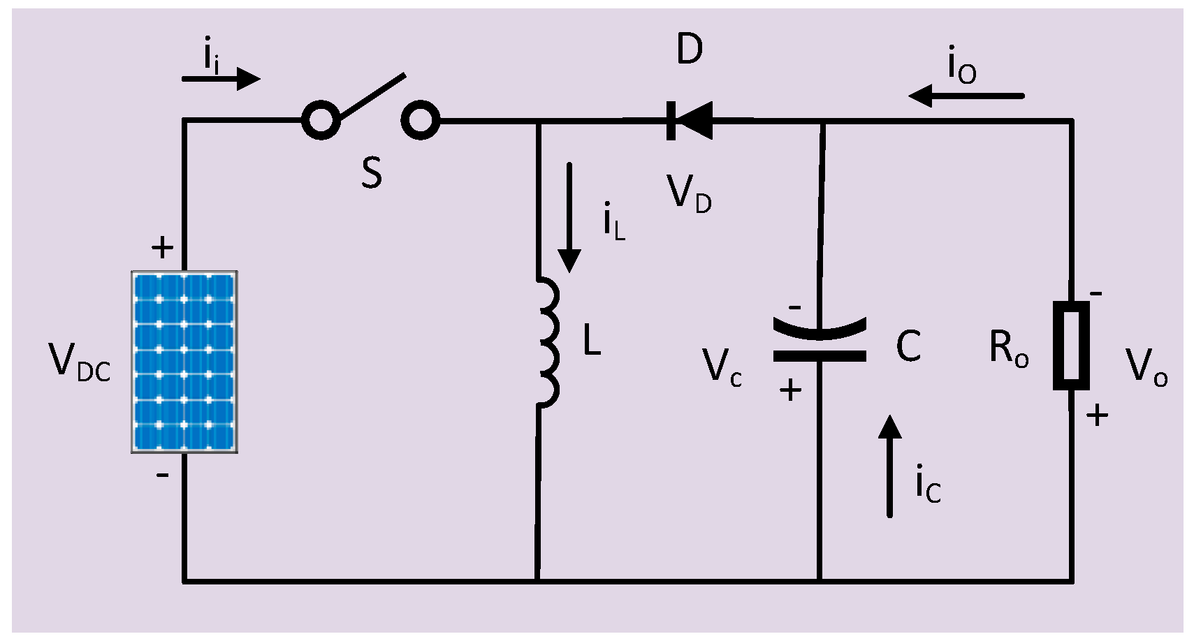
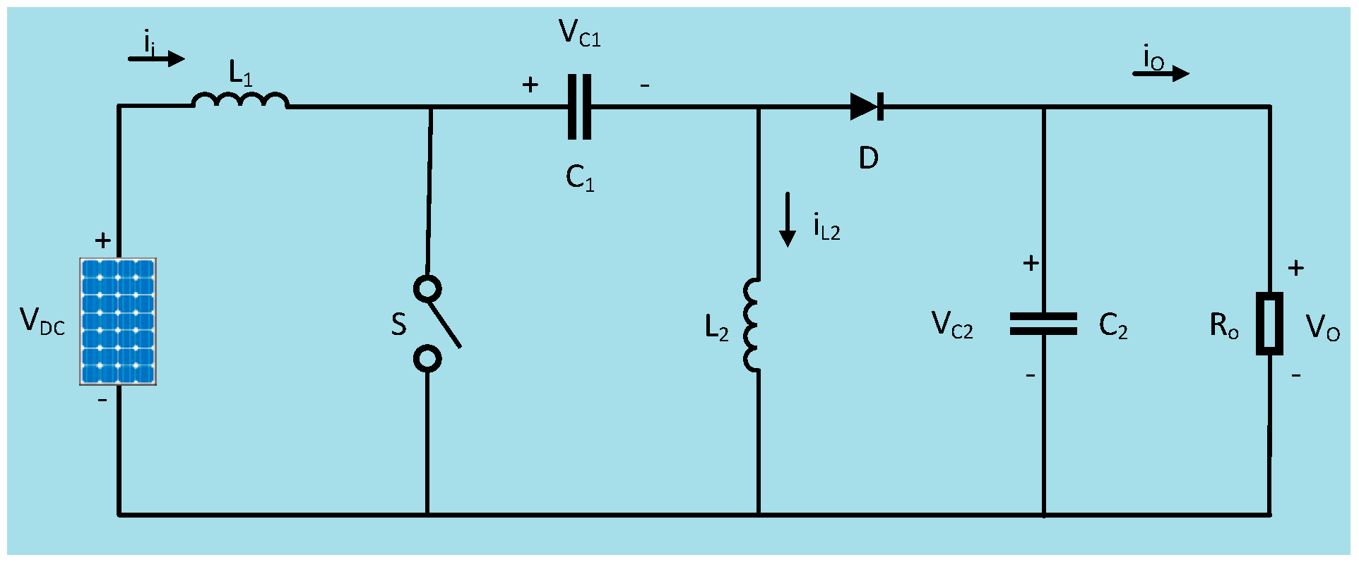
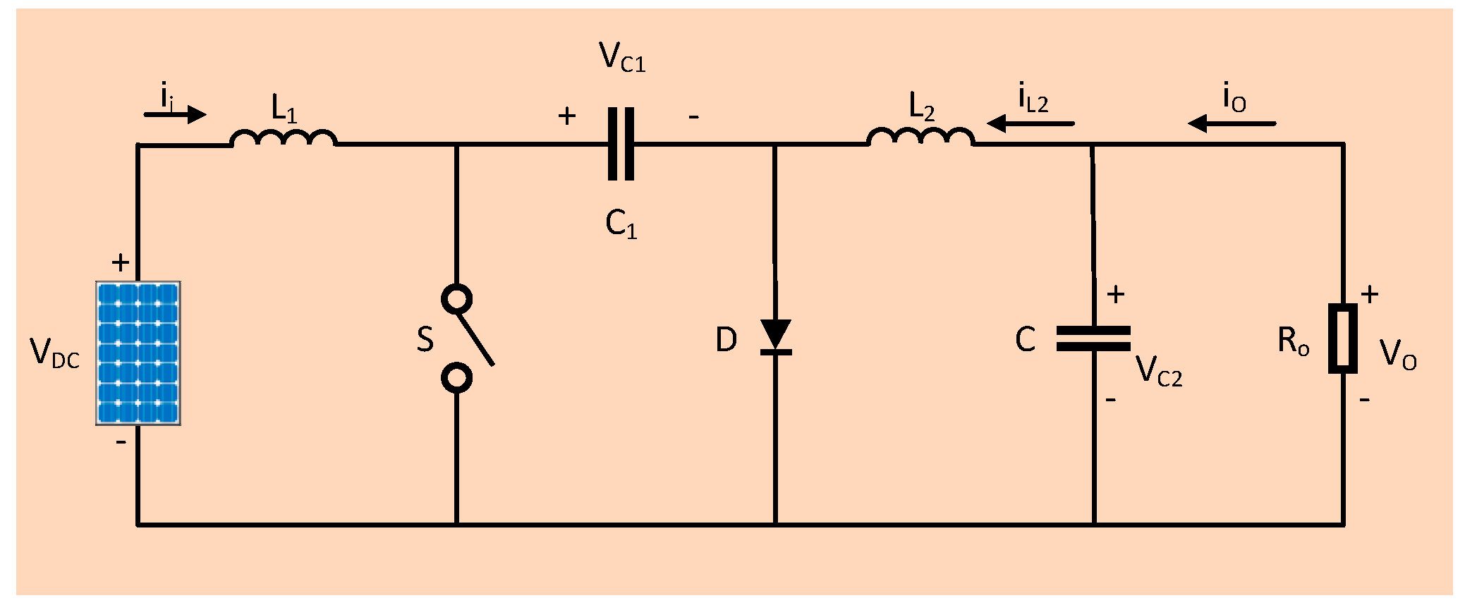
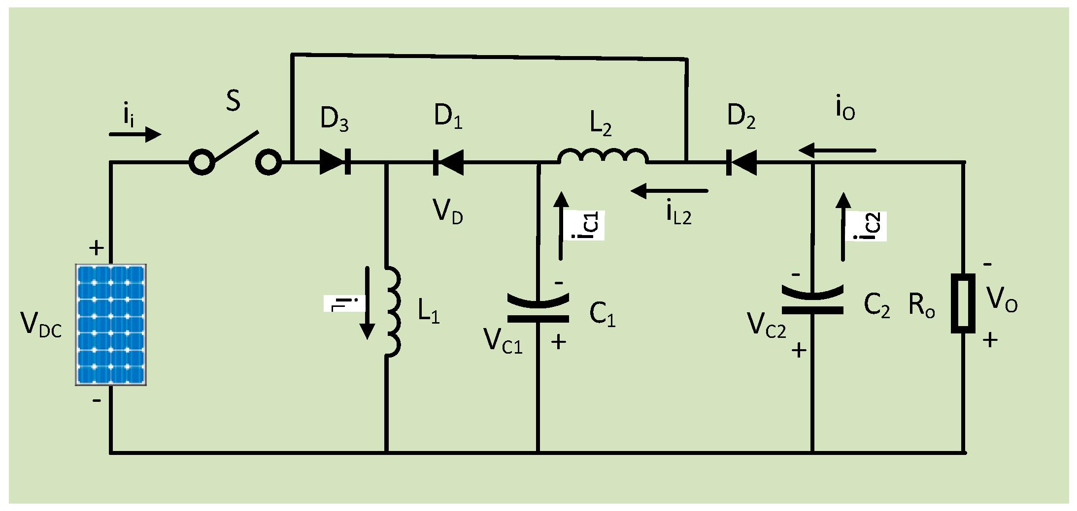
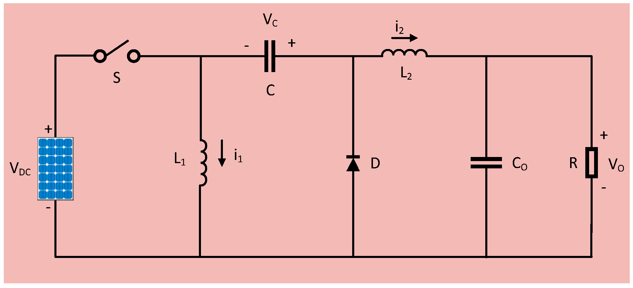
3.5. Cuk Converter

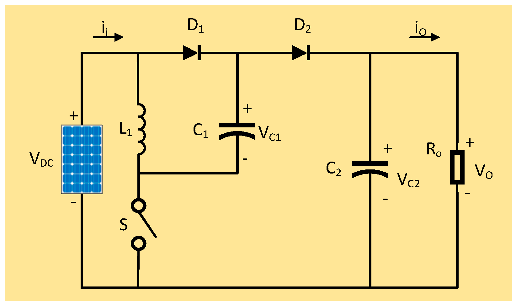
3.6. Positive-Output Super-Lift Luo Converter
3.7. Ultra-Lift Luo Converter
3.8. Zeta Converter
4. Isolated DC–DC Converter Topologies
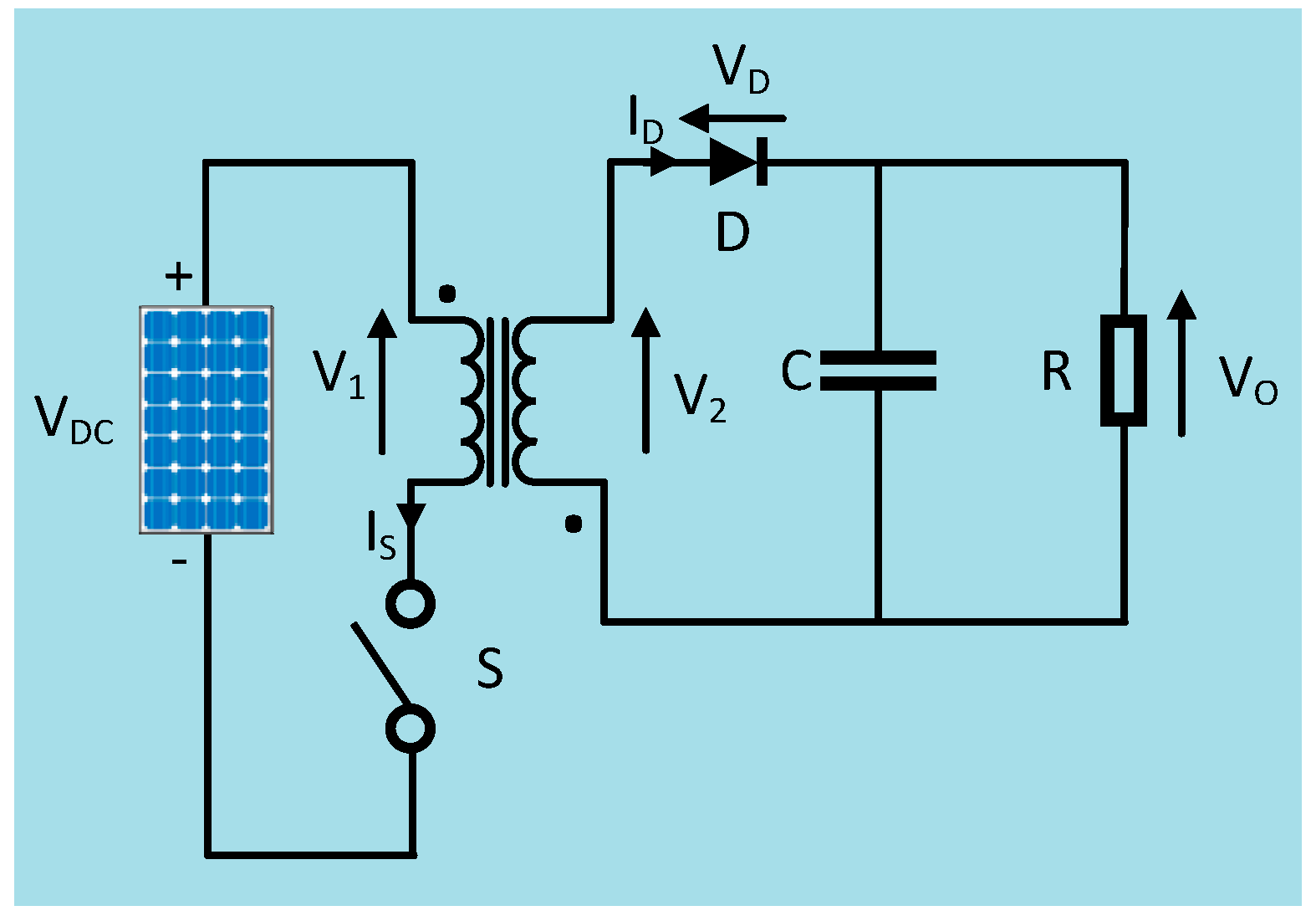
4.1. Flyback Converter
4.2. Bridge Converter
4.2.1. Half-Bridge Converter
4.2.2. Full-Bridge Converter
4.2.3. Dual Active Bridge Converter
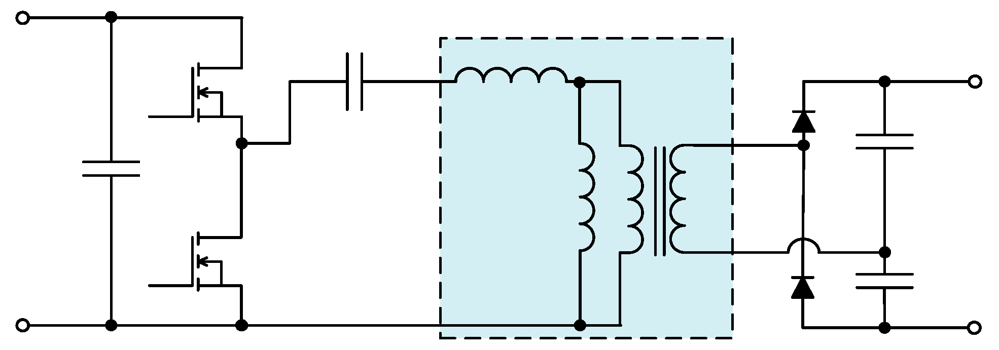
4.2.4. Multi-Element Resonant Converter
- (a)
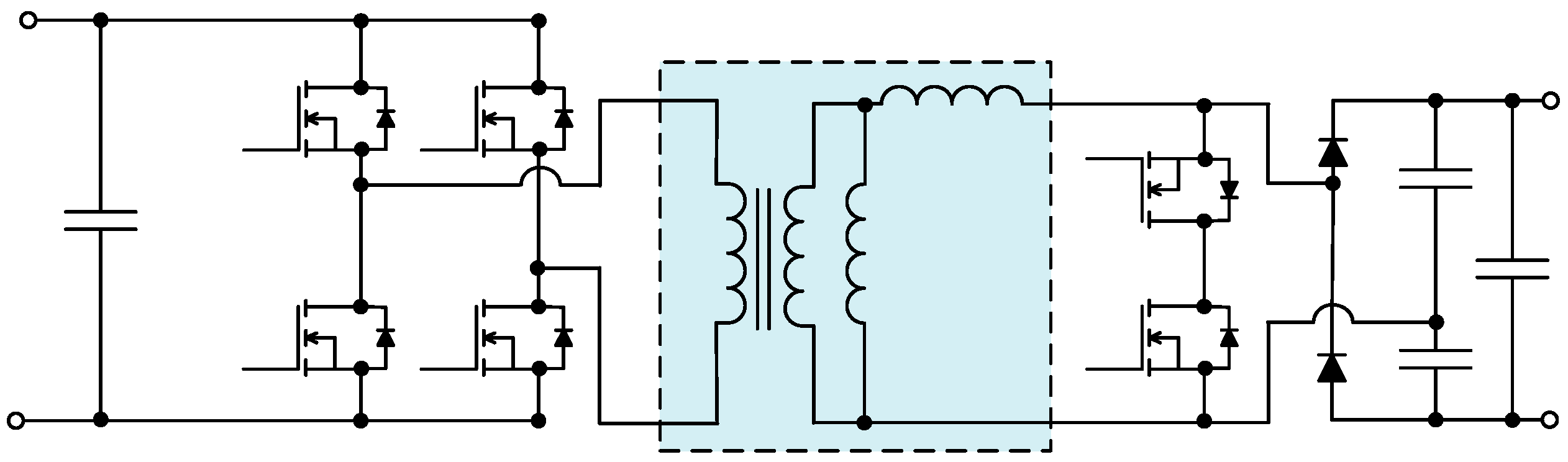
- Three elements LLC resonant converter Figure 16b: The resonant tank was formed using three LLC element and it is considered to be a bandpass filter in a circuit which comprises parallel resonant frequency (PRF) and series resonant frequency (SRF) [130,131]. The series resonant frequency is created by the capacitor and inductor of the resonant tank. The fundamental component of input energy can be distributed form source to load very efficiently at this topology. Therefore, high power conversion efficiency can be achieved very easily using this topology. However, to achieve the proper damping effect, the frequency must be increased largely as it has poor frequency selectivity and very wide bandwidth. An additional resonant element must be added for improving the characteristics of this topology.
- (b)
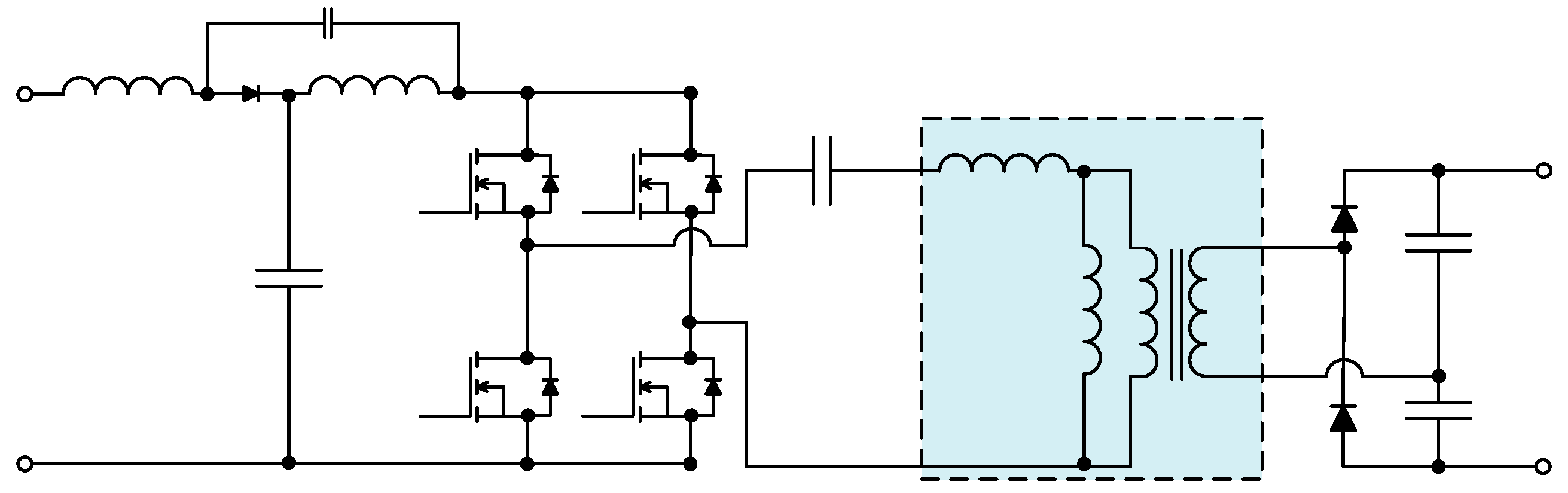
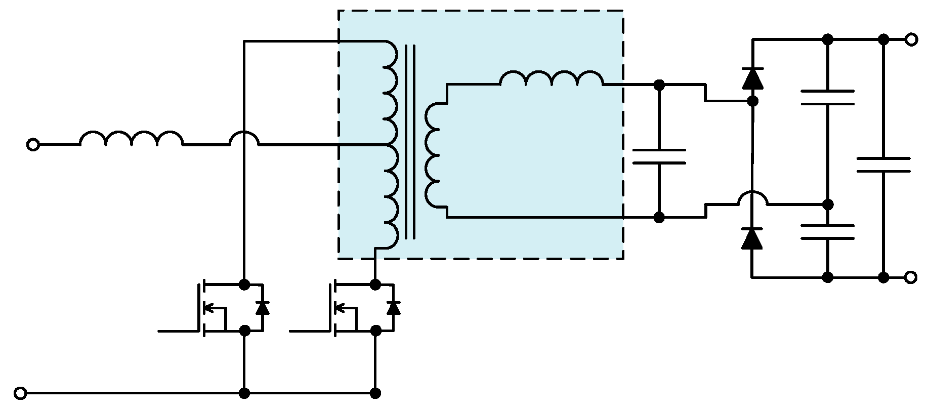
- Four-element resonant converter, as shown in Figure 16c: The LCLC four-element converter is 3-element LLC-based resonant topology [132,133]. The magnetic construction and resonant parameter design method for four-element topologies are simple in logic and accurate. It achieves high voltage gain and high conversion efficiency. This topology is particularly suitable for wide input voltage applications such as standalone energy system. It experiences optimum weighted efficiency over the extensive input voltage range.
- (c)
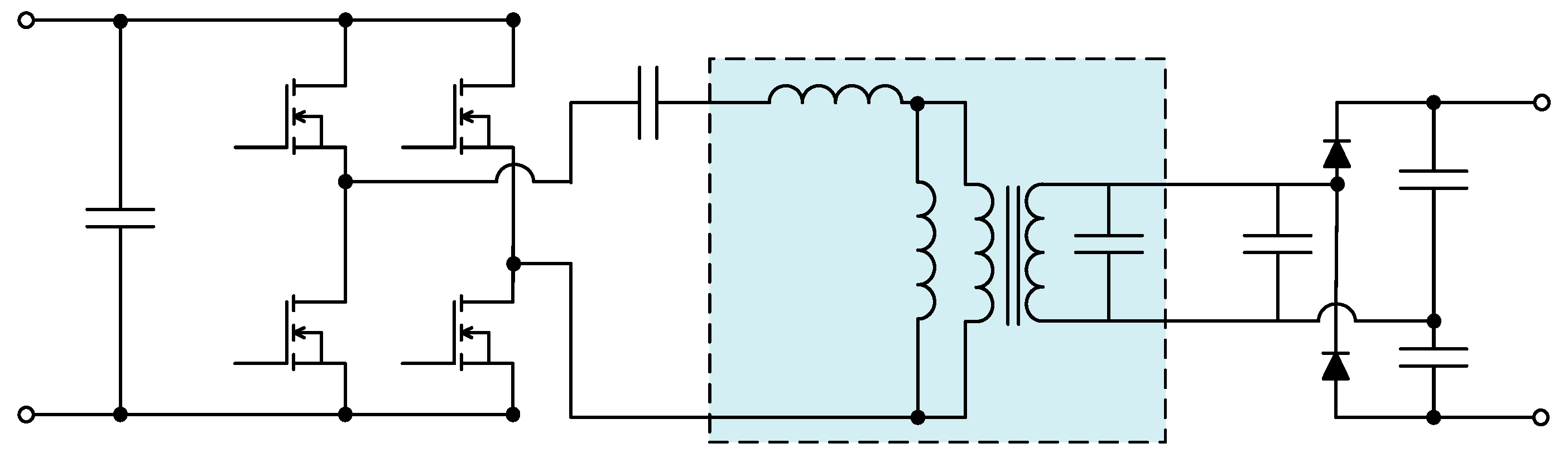
- Five-element resonant converter, as shown in Figure 16d: The five-element LLC-LC resonant converter is implemented by adding two LC elements into the secondary side of the traditional conventional LLC converter [134]. The additional two LC elements called notch filter which increases the voltage gain of the traditional converter through reducing the conduction losses. Furthermore, the five-element resonant converter provides high voltage gain at the resonance frequency and can minimize the circulating energy of the resonant tank. In other case, the five-element LCLCL resonant tank is adopted with half the bride at the primary side. These topologies ease to combine with other output structures such as voltage doubler, full-bridge, and current-doubler structures. The circulating energy of the resonant tank can be reduced largely that lower than the conventional resonant converter [135].
- (d)
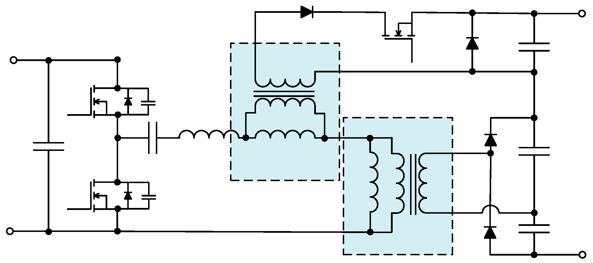
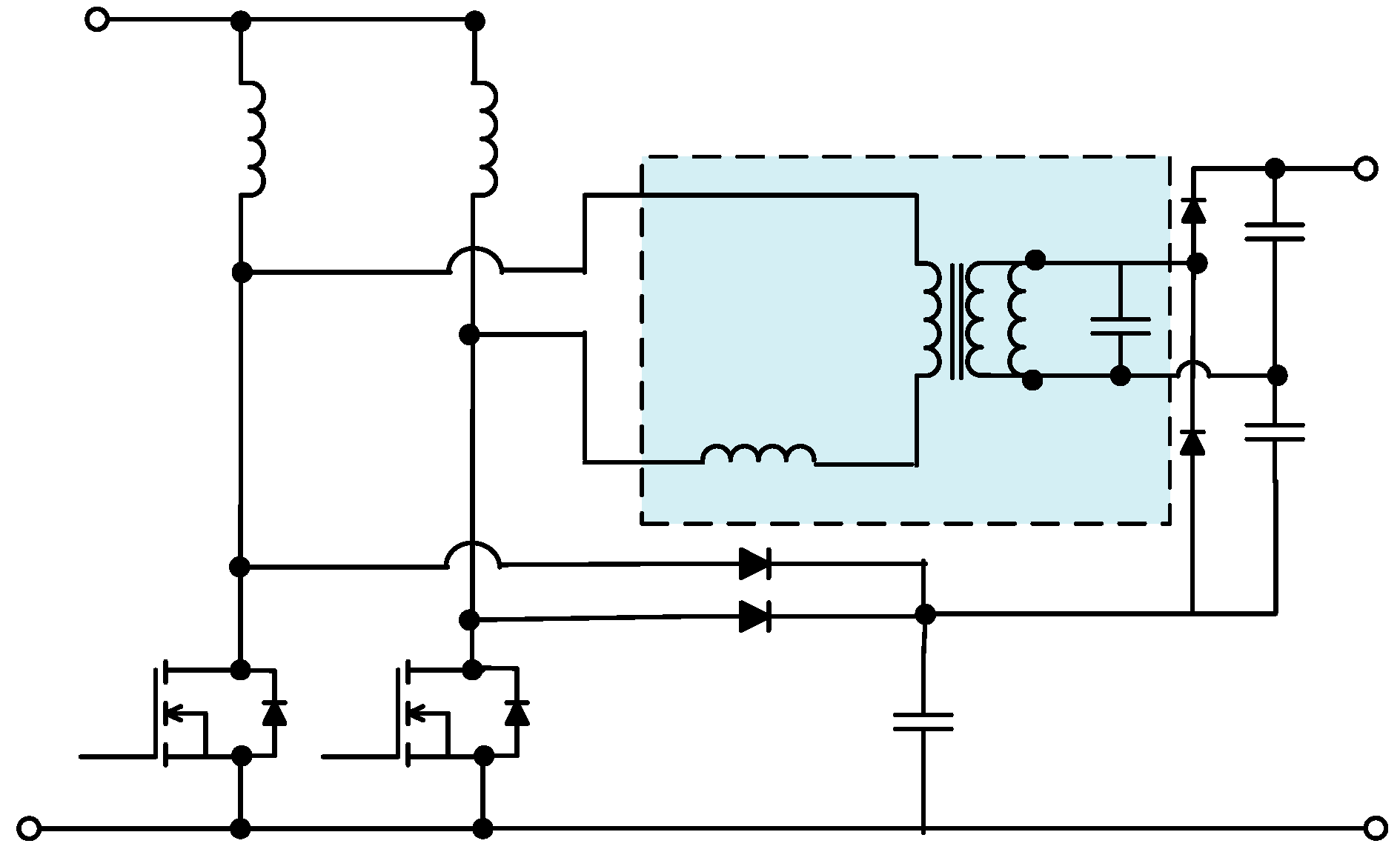
- Three port bidirectional multi-element resonant converter, as shown in Figure 16e: This converter transmits more active power to load due to the employment of third order harmonic components and fundamental components. Besides, a non-ideal isolated transformer is considered to be the parasitic leakage inductor is often ignored for the multi-element resonant converter. In this topology, zero voltage switching characteristics for all the three-port power switches can be achieved easily and around 96% power conversion efficiency is achieved. This achieves a more flexible and elegant design compared to the complex decoupling matrices. It is also simple to make digital control implementation for this topology [136].

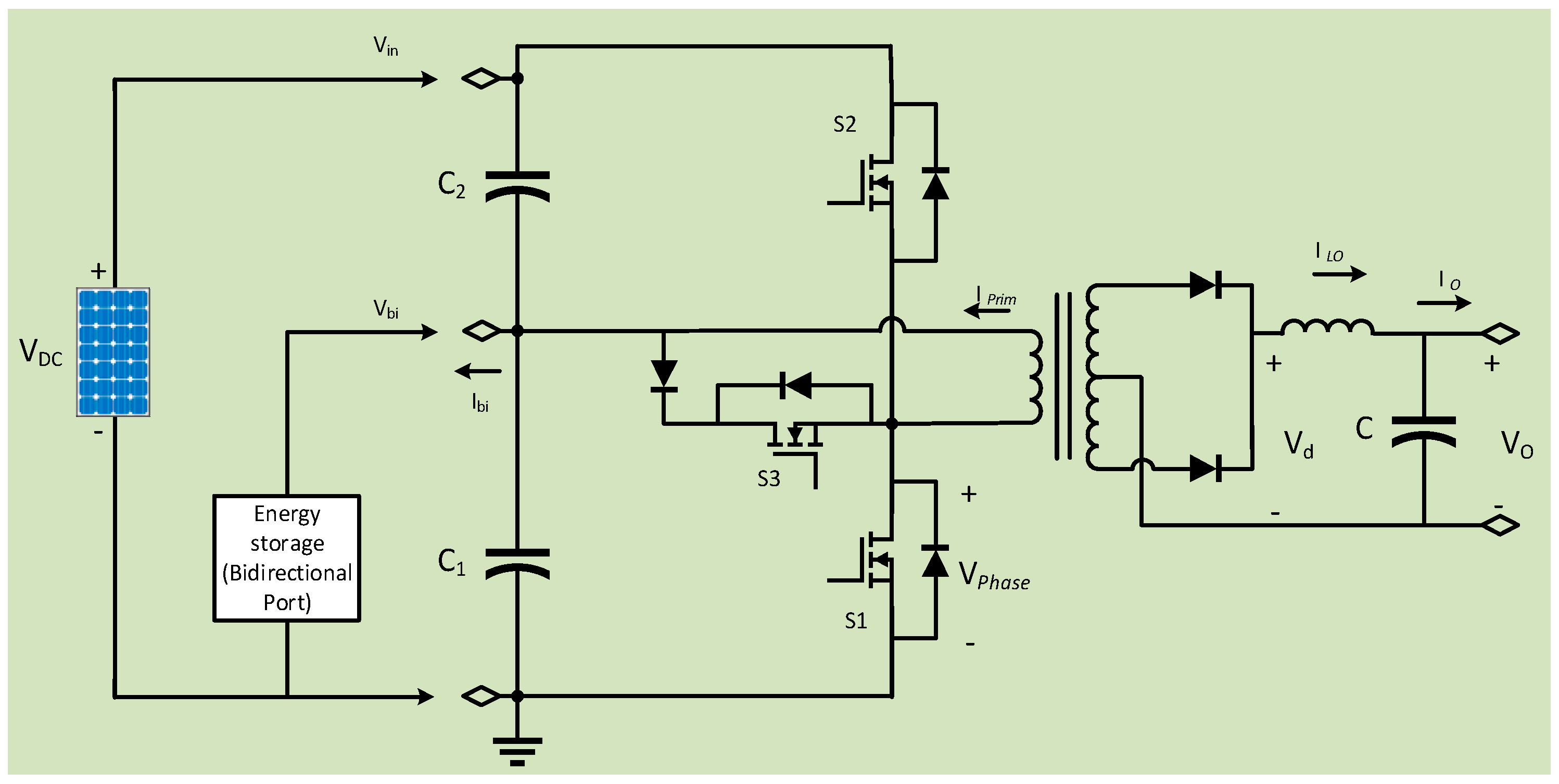
4.2.5. Push-Pull Converter Model
5. MPPT Techniques
6. Modulation Strategies
7. Comparative Performance Assessment
8. Advances in DC–DC Converters for PV Systems
9. Conclusions
Author Contributions
Acknowledgments
Conflicts of Interest
References
- Khare, V.; Nema, S.; Baredar, P. Status of solar wind renewable energy in India. Renew. Sustain. Energy Rev. 2013, 27, 1–10. [Google Scholar] [CrossRef] [Green Version]
- Nagayoshi, H. I-V curve simulation by multi-module simulator using I-V magnifier circuit. Sol. Energy Mater. Sol. Cells 2004, 82, 159–167. [Google Scholar] [CrossRef]
- Zeb, K.; Islam, S.U.; Din, W.U.; Khan, I.; Ishfaq, M.; Busarello, T.D.C.; Ahmad, I.; Kim, H.J. Design of Fuzzy-PI and Fuzzy-Sliding Mode Controllers for Single-Phase Two-Stages Grid-Connected Transformerless Photovoltaic Inverter. Electronics 2019, 8, 520. [Google Scholar] [CrossRef] [Green Version]
- Gaikwad, K.; Lokhande, S. Novel maximum power point tracking algorithm (MPPT) for solar tree application. In Proceedings of the 2015 International Conference on Energy Systems and Applications, Pune, India, 30 October–1 November 2015; pp. 189–193. [Google Scholar]
- Available online: https://www.iea-shc.org/Data/Sites/1/publications/task16-photovoltaics_in_buildings-full.pdf (accessed on 13 December 2019).
- Dong, L.; Fujing, D.; Yanbo, W.; Zhe, C. Improved Control Strategy for T-type Isolated DC/DC Converters. J. Power Electron. 2017, 17, 874–883. [Google Scholar]
- Wai, R.J.; Lin, C.Y.; Duan, R.Y.; Chang, Y.R. High-efficiency dc-dc converter with high voltage gain and reduced switch stress. IEEE Trans. Ind. Electron. 2007, 54, 354–364. [Google Scholar] [CrossRef]
- Gu, B.; Dominic, J.; Lai, J.S.; Zhao, Z.; Liu, C. High boost ratio hybrid transformer DC-DC converter for photovoltaic module applications. IEEE Trans. Power Electron. 2013, 28, 2048–2058. [Google Scholar] [CrossRef]
- Olalla, C.; Clement, D.; Rodriguez, M.; Maksimovic, D. Architectures and control of submodule integrated dc-dc converters for photovoltaic applications. IEEE Trans. Power Electron. 2013, 28, 2980–2997. [Google Scholar] [CrossRef]
- Huusari, J.; Suntio, T. Origin of cross-coupling effects in distributed DC-DC converters in photovoltaic applications. IEEE Trans. Power Electron. 2013, 28, 4625–4635. [Google Scholar] [CrossRef]
- Bhattacharjee, S.; Saharia, B.J. A comparative study on converter topologies for maximum power point tracking application in photovoltaic generation. J. Renew. Sustain. Energy 2014, 6, 053140. [Google Scholar] [CrossRef]
- Ahmed, N.A. Advanced energy conversion system using sinusoidal voltage tracking buck–boost converter cascaded polarity changing inverter. In Proceedings of the AIP Conference Proceedings; American Institute of Physics: College Park, MD, USA, 2011; Volume 48, p. 1337. [Google Scholar]
- Ribeiro, E.; Cardoso, A.J.M.; Boccaletti, C. Fault-tolerant strategy for a photovoltaic DC–DC converter. IEEE Trans. Power Electron. 2013, 28, 3008–3018. [Google Scholar] [CrossRef]
- Myers, I.T.; Baumann, E.D. Multimegawatt inverter/converter technology for space power applications. In Proceedings of the AIP Conference Proceedings; American Institute of Physics: College Park, MD, USA, 1992; Volume 246, p. 401. [Google Scholar]
- Caro, J.C.R.; Maldonado, J.C.M.; Bautista, R.F.V.; Gonzalez, A.V.; Cabrera, R.S.; Resendiz, J.E.V. Hybrid Voltage-Multipliers Based Switching Power Converters. In Proceedings of the AIP Conference Proceedings; American Institute of Physics: College Park, MD, USA, 2011; Volume 29, p. 1373. [Google Scholar]
- Peng, F.Z.; Li, H.; Su, G.J.; Lawler, J.S. A new ZVS bidirectional DC-DC converter for fuel cell and battery application. IEEE Trans. Power Electron. 2004, 19, 54–55. [Google Scholar] [CrossRef] [Green Version]
- Chen, Y.; Huang, A.Q.; Yu, X. A High Step-Up Three-Port DC–DC Converter for Stand-Alone PV/Battery Power Systems. IEEE Trans. Power Electron. 2013, 28, 5049–5062. [Google Scholar] [CrossRef]
- Zhu, Y.; Xiao, W. A comprehensive review of topologies for photovoltaic I-V curve tracer. Sol. Energy 2020, 196, 346–357. [Google Scholar] [CrossRef]
- Rehman, Z.; Al-Bahadly, I.; Mukhopadhyay, S. Multiinput DC–DC converters in renewable energy applications—An overview. Renew. Sustain. Energy Rev. 2015, 41, 521–539. [Google Scholar] [CrossRef]
- Sivakumar, S.; Sathik, M.J.; Manoj, P.S.; Sundararajan, G. An assessment on performance of DC–DC converters for renewable energy applications. Renew. Sustain. Energy Rev. 2016, 58, 1475–1485. [Google Scholar] [CrossRef]
- Khosrogorji, S.; Ahmadian, M.; Torkaman, H.; Soori, S. Multi-input DC/DC converters in connection with distributed generation units—A review. Renew. Sustain. Energy Rev. 2016, 66, 360–379. [Google Scholar] [CrossRef]
- Zhang, N.; Sutanto, D.; Muttaqi, K.M. A review of topologies of three-port DC-DC converters for the integration of renewable energy and energy storage system. Renew. Sustain. Energy Rev. 2016, 56, 388–401. [Google Scholar] [CrossRef] [Green Version]
- Sri Revathi, B.; Prabhakar, M. Non isolated high gain DC–DC converter topologies for PV applications—A comprehensive review. Renew. Sustain. Energy Rev. 2016, 66, 920–933. [Google Scholar] [CrossRef]
- Arunkumari, T.; Indragandhi, V. An overview of high voltage conversion ratio DC–DC converter configurations used in DC micro-grid architectures. Renew. Sustain. Energy Rev. 2017, 77, 670–688. [Google Scholar] [CrossRef]
- Dileep, G.; Singh, S.N. Selection of non-isolated DC–DC converters for solar photovoltaic system. Renew. Sustain. Energy Rev. 2017, 76, 1230–1247. [Google Scholar]
- Reshma Gopi, R.; Sreejith, S. Converter topologies in photovoltaic applications—A review. Renew. Sustain. Energy Rev. 2018, 94, 1–14. [Google Scholar] [CrossRef]
- Hossain, M.Z.; Rahim, N.A.; Selvaraj, J. Recent progress and development on power DC–DC converter topology, control, design and applications: A review. Renew. Sustain. Energy Rev. 2018, 81, 205–230. [Google Scholar] [CrossRef]
- Amir, A.; Amir, A.; Che, H.S.; Elkhateb, A.; Rahim, N.A. Comparative analysis of high voltage gain DC–DC converter topologies for photovoltaic systems. Renew. Energy 2019, 126, 1147–1163. [Google Scholar] [CrossRef] [Green Version]
- Al-Maamary, H.M.S.; Kazem, H.A.; Chaichan, M.T. Changing the energy profile of the GCC states: A review. Int. J. Appl. Eng. Res. 2016, 11, 1980–1988. [Google Scholar]
- Denholm, P.; Margolis, R.M. Evaluating the limits of solar photovoltaics (PV) in traditional electric power systems. Energy Policy 2007, 35, 2852–2861. [Google Scholar] [CrossRef]
- Zeb, K.; Uddin, W.; Khan, M.A.; Ali, Z.; Ali, M.U.; Christofides, N.; Kim, H.J. A Comprehensive Review of Inverter Topologies and Control Strategies for Grid Connected Photovoltaic System. Renew. Sustain. Energy Rev. 2018, 94, 1120–1141. [Google Scholar] [CrossRef]
- Wind Energy and Solar|Installed GW Capacity-Global and by Country. Available online: http://www.fi-powerweb.com/Renewable-Energy.html (accessed on 2 October 2019).
- Zeb, K.; Khan, I.; Uddin, W.; Khan, M.A.; Sathishkumar, P.; Busarello, T.D.C.; Ahmad, I.; Kim, H.J. A Review of Recent Advances and Future Trends of Transformerless Inverter Structures for Single-Phase Grid-Connected Photovoltaic Systems. Energies 2018, 11, 1968. [Google Scholar] [CrossRef] [Green Version]
- Yusivar, F.; Farabi, M.Y.; Suryadiningrat, R.; Ananduta, W.W.; Syaifudin, Y. Buck-converter photovoltaic simulator. Int. J. Power Electron. Drive Syst. 2011, 2, 156–167. [Google Scholar] [CrossRef]
- Rashid, M.H. Power Electronics Handbook; Academic Press: New York, NY, USA, 2001. [Google Scholar]
- Mohan, N.T.; Undeland, M.; Robbins, W.P. Power Electronics: Converters, Applications and Design, 3rd ed.; John Wiley & Sons: New York, NY, USA, 2004. [Google Scholar]
- Elgendy, M.A.; Zahawi, B.; Atkinson, D.J. Assessment of perturb and observe MPPT algorithm implementation techniques for PV pumping applications. IEEE Trans. Sustain. Energy 2012, 3, 21–33. [Google Scholar] [CrossRef]
- Masoum, M.A.S.; Badejani, S.M.M.; Fuchs, E.F. Microprocessor-controlled new class of optimal battery chargers for photovoltaic applications. IEEE Trans. Energy Convers. 2004, 19, 599–606. [Google Scholar] [CrossRef]
- Saravana Ilango, G.; Srinivasa Rao, P.; Karthikeyan, A.; Nagamani, C. Single-stage sine-wave inverter for an autonomous operation of solar photovoltaic energy conversion system. Renew. Energy 2010, 35, 275–282. [Google Scholar] [CrossRef]
- Femia, N.; Granozio, D.; Petrone, G.; Spagnuolo, G.; Vitelli, M. Optimized one-cycle control in photovoltaic grid connected applications. IEEE Trans. Aerosp. Electron. Syst. 2006, 42, 954–972. [Google Scholar] [CrossRef]
- Peyman, K.; Syyed, M.M.; Morteza, D.; Motab, A.; Amirhossein, M. A High Efficiency DC/DC Boost Converter for Photovoltaic Applications. Int. J. Soft Comput. Eng. 2016, 6, 31–37. [Google Scholar]
- Saravanan, S.; Babu, N.R. A modified high step-up non-isolated DC–DC converter for PV application. J. Appl. Res. Technol. 2017, 15, 242–247. [Google Scholar] [CrossRef]
- Forouzesh, M.; Siwakoti, Y.P.; Gorji, S.A.; Blaabjerg, F.; Lehman, B. Step-Up DC–DC converters: A comprehensive review of voltage-boosting techniques, topologies, and applications. IEEE Trans. Power Electron. 2017, 32, 9143–9178. [Google Scholar] [CrossRef]
- Huber, L.; Jovanovic, M.M. A design approach for server power supplies for networking applications. In Proceedings of the APEC 2000, Fifteenth Annual IEEE Applied Power Electronics Conference and Exposition (Cat. No.00CH37058), New Orleans, LA, USA, 6–10 February 2000; Volume 2, pp. 1163–1169. [Google Scholar]
- Salvador, M.A.; Lazzarin, T.B.; Coelho, R.F. High Step-Up DC–DC Converter with Active Switched-Inductor and Passive Switched-Capacitor Networks. IEEE Trans. Ind. Electron. 2018, 65, 5644–5654. [Google Scholar] [CrossRef]
- Wai, R.-J.; Duan, R.-Y.; Jheng, K.-H. High-efficiency bidirectional DC–DC converter with high-voltage gain. IET Power Electron. 2012, 152, 793. [Google Scholar] [CrossRef]
- Howlader, A.M.; Urasaki, N.; Senjyu, T.; Yona, A.; Saber, A.Y. Optimal PAM control for a buck boost DC–DC converter with a wide-speed-range of operation for a PMSM. J. Power Electron. 2010, 10, 477–484. [Google Scholar] [CrossRef] [Green Version]
- Ned Mohan. Power Electronics and Drives; Indian Institute of Technology: Guwahati, India, 2003. [Google Scholar]
- Zhang, Y.; Sen, P.C. A new soft-switching technique for buck, boost, and buck–boost converters. IEEE Trans. Ind. Appl. 2003, 39, 1775–1782. [Google Scholar] [CrossRef]
- Lee, Y.J.; Khaligh, A.; Chakraborty, A.; Emadi, A. Digital Combination of Buck and Boost Converters to Control a Positive Buck-Boost Converter and Improve the Output Transients. IEEE Trans. Power Electron. 2009, 24, 1267–1279. [Google Scholar] [CrossRef]
- Gaboriault, M.; Notman, A. A high efficiency, non-inverting, buck–boost DC–DC converter. In Proceedings of the Nineteenth Annual IEEE Applied Power Electronics Conference and Exposition (APEC′04), Anaheim, CA, USA, 22–26 February 2004; Volume 3, pp. 1411–1415. [Google Scholar]
- Kang, F.S.; Park, S.J.; Cho, S.E.; Kim, J.M. Photovoltaic power interface circuit incorporated with a buck-boost converter and a full-bridge inverter. Appl. Energy 2005, 82, 266–283. [Google Scholar] [CrossRef]
- Sahu, B.; Rincon-Mora, G.A. A low voltage, dynamic, noninverting, synchronous buck-boost converter for portable applications. IEEE Trans. Power Electron. 2004, 19, 443–452. [Google Scholar] [CrossRef]
- Benavides, N.D.; Chapman, P.L. Power budgeting of a multiple-input buck–boost converter. IEEE Trans. Power Electron. 2005, 20, 1303–1309. [Google Scholar] [CrossRef]
- Ahmed, K.T.; Datta, M.; Mohammad, N. A novel two switch non-inverting buck–boost converter-based maximum power point tracking system. Int. J. Electron. Comput. Eng. 2013, 3, 467–477. [Google Scholar]
- Bose, B.K. Power Electronics, Smart Grid, and Renewable Energy Systems. Proc. IEEE 2017, 105, 2011–2018. [Google Scholar] [CrossRef]
- Chiang, S.J.; Shieh, H.J.; Chen, M.C. Modeling and control of PV charger system with SEPIC converter. IEEE Trans. Ind. Electron. 2009, 56, 4344–4353. [Google Scholar] [CrossRef]
- Niculescu, E.; Marius, C.N.; Dorina, M.P. Modelling the PWM SEPIC converter in discontinuous conduction mode. In Proceedings of the 11th International Conference on Circuits (WSEAS), Crete Island, Greece, 23–25 July 2007. [Google Scholar]
- Al-Saffar, M.A.; Ismail, E.H.; Sabzali, A.J.; Fardoun, A.A. An improved topology of SEPIC converter with reduced output voltage ripple. IEEE Trans. Power Electron. 2008, 23, 2377–2386. [Google Scholar] [CrossRef]
- Chen, J.; Chang, C. Analysis and design of SEPIC converter in boundary conduction mode for universal-line power factor correction applications. In Proceedings of the 2001 IEEE 32nd Annual Power Electronics Specialists Conference (IEEE Cat. No.01CH37230), Vancouver, BC, Canada, 17–21 June 2001; Volume 2, pp. 742–747. [Google Scholar]
- Mamarelis, E.; Petrone, G.; Spagnuolo, G. Design of a sliding-mode-controlled SEPIC for PV MPPT applications. IEEE Trans. Ind. Electron. 2014, 61, 3387–3398. [Google Scholar] [CrossRef]
- El Khateb, A.; Rahim, N.A.; Selvaraj, J.; Uddin, M.N. Fuzzy-logic-controller-based SEPIC converter for maximum power point tracking. IEEE Trans. Ind. Appl. 2014, 50, 2349–2358. [Google Scholar] [CrossRef]
- Park, H.E.; Song, J.H. A dP/dV feedback-controlled MPPT method for photovoltaic power system using II-SEPIC. J. Power Electron. 2009, 9, 604–611. [Google Scholar]
- Linares-Flores, J.; Sira-Ramírez, H.; Cuevas-López, E.F.; Contreras-Ordaz, M.A. Sensor less passivity-based control of a DC motor via a solar powered sepic converter-full bridge combination. J. Power Electron. 2011, 11, 743–750. [Google Scholar] [CrossRef] [Green Version]
- Kim, I.D.; Kim, J.Y.; Nho, E.C.; Kim, H.G. Analysis and design of a soft-switched PWM Sepic DC–DC converter. J. Power Electron. 2010, 10, 461–467. [Google Scholar] [CrossRef]
- Song, M.S.; Son, Y.D.; Lee, K.H. Non-isolated Bidirectional soft-switching SEPIC/ZETA converter with reduced ripple currents. J. Power Electron. 2014, 14, 649–660. [Google Scholar] [CrossRef]
- Singh, M.D. Power Electronics; Tata McGraw-Hill Education: New Delhi, India, 2008. [Google Scholar]
- Bist, V.; Singh, B. PFC Cuk converter-fed BLDC motor drive. IEEE Trans. Power Electron. 2015, 30, 871–887. [Google Scholar] [CrossRef]
- Spiazzi, G.; Mattavelli, P. Design criteria for power factor pre regulators based on SEPIC and Cuk converters in continuous conduction mode. In Proceedings of the 1994 IEEE Industry Applications Society Annual Meeting, Denver, CO, USA, 2–6 October 1994. [Google Scholar]
- Tse, C.K.; Lai, Y.M.; Lu, H.H.C. Hopf bifurcation and chaos in a free-running current-controlled Ćuk switching regulator. IEEE Trans. Circuits Syst. I Fundam. Theory Appl. 2000, 47, 448–457. [Google Scholar] [CrossRef] [Green Version]
- Moghaddam, A.F.; Van den Bossche, A. A ćuk converter cell balancing technique by using coupled inductors for lithium-based batteries. Energies 2019, 12, 2881. [Google Scholar] [CrossRef] [Green Version]
- Zhu, M.; Luo, F.L. Enhanced self-lift Cûk converter for negative-to-positive voltage conversion. IEEE Trans. Power Electron. 2010, 25, 2227–2233. [Google Scholar] [CrossRef]
- Axelrod, B.; Berkovich, Y.; Tapuchi, S.; Ioinovici, A. Steep Conversion ratio Ćuk, Zeta, and Sepic converters based on a switched coupled-inductor cell. In Proceedings of the 2008 IEEE Power Electronics Specialists Conference, Rhodes, Greece, 15–19 June 2008; pp. 3009–3014. [Google Scholar]
- Fardoun, A.A.; Ismail, E.H.; Sabzali, A.J.; Al-Saffar, M.A. New efficient bridgeless cuk rectifiers for PFC applications. IEEE Trans. Power Electron. 2012, 27, 3292–3301. [Google Scholar] [CrossRef]
- Lin, B.R.; Chen, J.J.; Shen, S.F. Zero voltage switching double-ended converter. IET Power Electron. 2010, 57, 908–912. [Google Scholar] [CrossRef]
- Kamnarn, U.; Chunkag, V. Analysis and design of a modular three-phase AC-to-DC converter using CUK rectifier module with nearly unity power factor and fast dynamic response. IEEE Trans. Power Electron. 2009, 24, 2000–2012. [Google Scholar] [CrossRef]
- Darwish, A.; Massoud, A.M.; Holliday, D.; Ahmed, S.; Williams, B.W. Single-Stage Three-Phase Differential-Mode Buck-Boost Inverters with Continuous Input Current for PV Applications. IEEE Trans. Power Electron. 2016, 31, 8218–8236. [Google Scholar] [CrossRef] [Green Version]
- Lee, S.W.; Lee, S.R.; Jeon, C.H. A New High Efficient Bi-directional DC / DC Converter in the Dual Voltage System. J. Electr. Eng. Technol. 2006, 1, 343–350. [Google Scholar] [CrossRef] [Green Version]
- Chen, Z. PI and sliding mode control of a Cuk converter. IEEE Trans. Power Electron. 2012, 27, 3695–3703. [Google Scholar] [CrossRef]
- Elmelegi, A.; Mokhtar Aly; Ahmed, E.M. Developing Phase-Shift PWM-Based Distributed MPPT Technique for Photovoltaic Systems. In Proceedings of the 2019 International Conference on Innovative Trends in Computer Engineering (ITCE’2019), Aswan, Egypt, 2–4 February 2019. [Google Scholar]
- Durán, E.; Andújar, J.M.; Segura, F.; Barragán, A.J. A high-flexibility DC load for fuel cell and solar arrays power sources based on DC–DC converters. Appl. Energy 2011, 88, 1690–1702. [Google Scholar] [CrossRef]
- Zhang, M.; Wang, F.; Yang, J.H. Novel Cuk circuit and its application in photovoltaic system. In Proceedings of the 2009 3rd International Conference on Power Electronics Systems and Applications (PESA), Hong Kong, China, 20–22 May 2009. [Google Scholar]
- Valencia, P.A.O.; Ramos-Paja, C.A. Sliding-Mode Controller for Maximum Power Point Tracking in Grid-Connected Photovoltaic Systems. Energies 2015, 8, 12363–12387. [Google Scholar] [CrossRef] [Green Version]
- Jiménez-Castillo, G.; Muñoz-Rodríguez, F.J.; Rus-Casas, C.; Gómez-Vidal, P. Improvements in Performance Analysis of Photovoltaic Systems: Array Power Monitoring in Pulse Width Modulation Charge Controllers. Sensors 2019, 19, 2150. [Google Scholar] [CrossRef] [Green Version]
- Tiwari, N.; Bhagwan, D.D. MPPT controller for photo voltaic systems using Cuk DC/DC convertor. Int. J. Adv. Technol. Eng. Res. (IJATER) 2012, 2, 164–169. [Google Scholar]
- Singh, B.; Bist, V.; Chandra, A.; Al-Haddad, K. Power Factor Correction in Bridgeless-Luo Converter-Fed BLDC Motor Drive. IEEE Trans. Ind. Appl. 2015, 51, 1179–1188. [Google Scholar] [CrossRef]
- Lin, L.F.; Ye, H. Advanced DC/DC Converters; CRC Press: Boca Raton, FL, USA, 2004. [Google Scholar]
- Luo, F.L.; Ye, H. Positive output cascade boost converters. IEE Proc. Electr. Power Appl. 2004, 18, 105–113. [Google Scholar] [CrossRef]
- Manikandan, A.; Vadivel, N. Design and Implementation of Luo Converter for Electric Vehicle Applications. Int. J. Eng. Trends Technol. (IJETT) 2013, 4, 4437–4441. [Google Scholar]
- Luo, F.L.; Ye, H. Hybrid split capacitors and split inductors applied in positive output super-lift Luo-converters. IET Power Electron. 2013, 6, 1759. [Google Scholar] [CrossRef]
- Berkovich, Y.; Axelrod, B.; Madar, R.; Twina, A. Improved Luo converter modifications with increasing voltage ratio. IET Power Electron. 2015, 8, 202–212. [Google Scholar] [CrossRef]
- Ramash Kumar, K.; Jeevananthan, S. Sliding mode control for current distribution control in paralleled positive output Elementary Super Lift Luo converters. J. Power Electron. 2011, 11, 639–654. [Google Scholar] [CrossRef] [Green Version]
- Lai, Y. Introduction to Power Electronics. In Proceedings of the IMID 2009, Seoul, Korea, 12–16 October 2009. [Google Scholar]
- Lin, L.F.; Ye, H. Essential DC/DC Converters; CRC Press: Boca Raton, FL, USA, 2010. [Google Scholar]
- Seyedmahmoudian, M.; Rahmani, R.; Mekhilef, S.; Maung Than Oo, A.; Stojcevski, A.; Soon, T.K.; Ghandhari, A.S. Simulation and Hardware Implementation of New Maximum Power Point Tracking Technique for Partially Shaded PV System Using Hybrid DEPSO Method. IEEE Trans. Sustain. Energy 2015, 6, 850–862. [Google Scholar] [CrossRef]
- Narula, S.; Singh, B.; Bhuvaneswari, G. Power Factor Corrected Welding Power Supply Using Modified Zeta Converter. IEEE J. Emerg. Sel. Top. Power Electron. 2016, 4, 617–625. [Google Scholar] [CrossRef]
- Wu, T.F.; Liang, S.A.; Chen, Y.M. Design optimization for asymmetrical ZVS-PWM Zeta converter. IEEE Trans. Aerosp. Electron. Syst. 2003, 39, 521–532. [Google Scholar]
- Bist, V.; Singh, B. Reduced sensor configuration of brushless DC motor drive using a power factor correction-based modified-zeta converter. IET Power Electron. 2014, 7, 2322. [Google Scholar] [CrossRef]
- Singh, S.; Singh, B.; Bhuvaneswari, G.; Bist, V. Power factor corrected zeta converter based improved power quality switched mode power supply. IEEE Trans. Ind. Electron. 2015, 62, 5422–5433. [Google Scholar] [CrossRef]
- Murthy-Bellur, D.; Kazimierczuk, M.K. Isolated two-transistor zeta converter with reduced transistor voltage stress. IEEE Trans. Circuits Syst. II Express Briefs 2011, 58, 41–45. [Google Scholar] [CrossRef]
- Lin, J.L.; Yang, S.P.; Lin, P.W. Small-signal analysis and controller design for an isolated zeta converter with high power factor correction. Electr. Power Syst. Res. 2005, 76, 67–76. [Google Scholar] [CrossRef]
- Andrade, A.M.S.S.; Beltrame, R.C.; Schuch, L.; Martins, M.L.D.S. PV module-integrated single-switch DC/DC converter for PV energy harvest with battery charge capability. In Proceedings of the 11th IEEE/IAS International Conference on Industry Applications, Juiz de Fora, Brazil, 7–10 December 2014; pp. 1–8. [Google Scholar]
- Gules, R.; Dos Santos, W.M.; Dos Reis, F.A.; Romaneli, E.F.R.; Badin, A.A. A modified SEPIC converter with high static gain for renewable applications. IEEE Trans. Power Electron. 2014, 29, 5860–5871. [Google Scholar] [CrossRef]
- Lu, D.D.C.; Agelidis, V.G. Photovoltaic-battery-powered DC bus system for common portable electronic devices. IEEE Trans. Power Electron. 2009, 24, 849–855. [Google Scholar] [CrossRef]
- Sukesh, N.; Pahlevaninezhad, M.; Jain, P.K. Analysis and implementation of a single stage flyback PV microinverter with soft switching. IEEE Trans. Ind. Electron. 2014, 61, 1819–1833. [Google Scholar] [CrossRef]
- Achille, E.; Martiré, T.; Glaize, C.; Joubert, C. Optimized dc-ac boost converters for modular photovoltaic grid-connected generators. In Proceedings of the IEEE International Symposium on Industrial Electronics, Ajaccio, France, 4–7 May 2004; Volume 2, pp. 1005–1010. [Google Scholar]
- Hsieh, Y.C.; Chen, M.R.; Cheng, H.L. An interleaved flyback converter featured with zero-voltage transition. IEEE Trans. Power Electron. 2011, 26, 79–84. [Google Scholar] [CrossRef]
- Wu, H.; Chen, R.; Zhang, J.; Xing, Y.; Hu, H.; Ge, H. A family of three-port half-bridge converters for a stand-alone renewable power system. IEEE Trans. Power Electron. 2011, 26, 2697–2706. [Google Scholar] [CrossRef]
- Truong, D.D.; Minh, K.N.; Young, C.L.; Joon, H.C. An Active-Clamped Current-Fed Half-bridge DC–DC Converter with Three Switches. In Proceedings of the International Power Electronics Conference (IPEC-Niigata 2018-ECCE Asia), Niigata, Japan, 20–24 May 2018. [Google Scholar]
- Baek, J., II; Kim, C.E.; Kim, K.W.; Lee, M.S.; Moon, G.W. Dual Half-Bridge LLC Resonant Converter with Hybrid-Secondary-Rectifier (HSR) for Wide-Ouput-Voltage Applications. In Proceedings of the 2018 International Power Electronics Conference, IPEC-Niigata-ECCE Asia 2018, Niigata, Japan, 20–24 May 2018; pp. 108–113. [Google Scholar]
- Hsieh, H.I.; Chiu, H.L.; Hsieh, G.C. Performance Study of High-Power Half-Bridge Interleaved LLC Converter. In Proceedings of the 2018 International Power Electronics Conference, IPEC-Niigata-ECCE Asia 2018, Niigata, Japan, 20–24 May 2018. [Google Scholar]
- Andrijanovitš, A.; Vinnikov, D.; Roasto, I.; Blinov, A. Three-level half-bridge ZVS DC/DC converter for electrolyzer integration with renewable energy systems. In Proceedings of the 10th International Conference on Environment and Electrical Engineering, Rome, Italy, 8–11 May 2011; pp. 1–4. [Google Scholar]
- Hu, W.; Wu, H.; Xing, Y.; Sun, K. A full-bridge three-port converter for renewable energy application. In Proceedings of the 2014 IEEE Applied Power Electronics Conference and Exposition-APEC 2014, Fort Worth, TX, USA, 16–20 March 2014. [Google Scholar]
- Cha, W.J.; Kwon, J.M.; Kwon, B.H. Highly Efficient Asymmetrical PWM Full-Bridge Converter for Renewable Energy Sources. IEEE Trans. Ind. Electron. 2016, 63, 2945–2953. [Google Scholar] [CrossRef]
- Patil, U.; Nagendrappa, H. Analysis and design of a high frequency isolated full bridge CLL resonant DC–DC converter for renewable energy applications. In Proceedings of the 2018 IEEE International Conference on Power, Instrumentation, Control and Computing (PICC 2018), Thrissur, India, 18–20 January 2018. [Google Scholar]
- Sathishkumar, P.; Himanshu; Piao, S.; Adil Khan, M.; Kim, D.H.; Kim, M.S.; Jeong, D.K.; Lee, C.; Kim, H.J. A blended SPS-ESPS control DAB-IBDC converter for a standalone solar power system. Energies 2017, 10, 1431. [Google Scholar] [CrossRef]
- Jeong, D.K.; Kim, H.S.; Baek, J.W.; Kim, J.Y.; Kim, H.J. Dual active bridge converter for Energy Storage System in DC microgrid. In Proceedings of the 2016 IEEE Transportation Electrification Conference and Expo, Asia-Pacific (ITEC Asia-Pacific 2016), Busan, Korea, 1–4 June 2016. [Google Scholar]
- Stieneker, M.; De Doncker, R.W. Dual-active bridge DC–DC converter systems for medium-voltage DC distribution grids. In Proceedings of the 2015 IEEE 13th Brazilian Power Electronics Conference and 1st Southern Power Electronics Conference (COBEP/SPEC 2016), Fortaleza, Brazil, 29 November–2 December 2015. [Google Scholar]
- Ryu, M.; Jung, D.; Baek, J.; Kim, H. An optimized design of bi-directional dual active bridge converter for low voltage battery charger. In Proceedings of the 16th International Power Electronics and Motion Control Conference and Exposition (PEMC 2014_, Antalya, Turkey, 21–24 September 2014. [Google Scholar]
- Naayagi, R.T.; Forsyth, A.J.; Shuttleworth, R. High-power bidirectional DC–DC converter for aerospace applications. IEEE Trans. Power Electron. 2012, 27, 4366–4379. [Google Scholar] [CrossRef]
- Zhao, B.; Song, Q.; Liu, W.; Sun, Y. Overview of dual-active-bridge isolated bidirectional DC–DC converter for high-frequency-link power-conversion system. IEEE Trans. Power Electron. 2014, 29, 4091–4106. [Google Scholar] [CrossRef]
- Zhou, H.; Khambadkone, A.M. Hybrid modulation for dual-active-bridge bidirectional converter with extended power range for ultracapacitor application. IEEE Trans. Ind. Appl. 2009, 45, 1434–1442. [Google Scholar] [CrossRef]
- Sathishkumar, P.; Krishna, T.N.V.; Himanshu; Khan, M.A.; Zeb, K.; Kim, H.J. Digital soft start implementation for minimizing start up transients in high power DAB-IBDC converter. Energies 2018, 11, 956. [Google Scholar] [CrossRef] [Green Version]
- Rodríguez, A.; Vázquez, A.; Lamar, D.G.; Hernando, M.M.; Sebastián, J. Different purpose design strategies and techniques to improve the performance of a dual active bridge with phase-shift control. IEEE Trans. Power Electron. 2015, 30, 790–804. [Google Scholar] [CrossRef]
- Khodabakhsh, J.; Moschopoulos, G. A study of multilevel resonant DC–DC converters for conventional DC voltage bus applications. In Proceedings of the Conference on IEEE Applied Power Electronics Conference and Exposition (APEC), San Antonio, TX, USA, 4–8 March 2018. [Google Scholar]
- Deng, J.; Li, S.; Hu, S.; Mi, C.C.; Ma, R. Design methodology of LLC resonant converters for electric vehicle battery chargers. IEEE Trans. Veh. Technol. 2014, 63, 1581–1592. [Google Scholar] [CrossRef]
- Jabbari, M.; Kazemi, H.; Hematian, N.; Shahgholian, G. A novel resonant LLC soft-switching buck converter. In Proceedings of the IEEE International Symposium on Industrial Electronics, Istanbul, Turkey, 1–4 June 2014. [Google Scholar]
- Sharifi, S.; Jabbari, M. Farzanehfard, H. A New Family of Single-Switch ZVS Resonant Converters. IEEE Trans. Ind. Electron. 2017. [Google Scholar] [CrossRef]
- Mishima, T.; Nakaoka, M. A new family of 2ZCS-PWM DC–DC converters with clamping diodes-assisted active edge-resonant cell. In Proceedings of the 2010 International Conference on Electrical Machines and Systems (ICEMS 2010), Incheon, Korea, 10–13 October 2010. [Google Scholar]
- Huang, D.; Lee, F.C.; Fu, D. Classification and selection methodology for multi-element resonant converters. In Proceedings of the Conference on IEEE Applied Power Electronics Conference and Exposition (APEC), Fort Worth, TX, USA, 6–11 March 2011. [Google Scholar]
- Huang, D.; Kong, P.; Lee, F.C.; Fu, D. A novel integrated multi-elements resonant converter. In Proceedings of the IEEE Energy Conversion Congress and Exposition: Energy Conversion Innovation for a Clean Energy Future (ECCE 2011), Proceedings, Phoenix, AZ, USA, 17–22 September 2011. [Google Scholar]
- Chen, Y.; Wang, H.; Liu, Y.F.; Afsharian, J.; Yang, Z.A. Efficiency-wise optimal design methodology of LCLC converter for wide input voltage range applications. In Proceedings of the 2016 IEEE Energy Conversion Congress and Exposition (ECCE), Milwaukee, WI, USA, 18–22 September 2016. [Google Scholar]
- Fu, D.; Lee, F.C.; Liu, Y.; Xu, M. Novel Multi-element resonant converters for front-end DC/DC converters. In Proceedings of the 2008 IEEE Power Electronics Specialists Conference, Rhodes, Greece, 15–19 June 2008; pp. 358–364. [Google Scholar]
- Wu, H.; Jin, X.; Hu, H.; Xing, Y. Multielement Resonant Converters with a Notch Filter on Secondary Side. IEEE Trans. Power Electron. 2016, 31, 3999–4004. [Google Scholar] [CrossRef]
- Mizutani, H.; Mishima, T.; Nakaoka, M. A dual pulse modulated five-element multi-resonant DC–DC converter and its performance evaluations. In Proceedings of the 2013 IEEE Energy Conversion Congress and Exposition (ECCE 2013), Denver, CO, USA, 15–19 September 2013. [Google Scholar]
- Wang, Y.; Han, F.; Yang, L.; Xu, R.; Liu, R. A Three-Port Bidirectional Multi-Element Resonant Converter with Decoupled Power Flow Management for Hybrid Energy Storage Systems. IEEE Access 2018, 6, 61331–61341. [Google Scholar] [CrossRef]
- Petit, P.; Aillerie, M.; Sawicki, J.P.; Charles, J.P. Push-pull converter for high efficiency photovoltaic conversion. Energy Procedia 2012, 18, 1583–1592. [Google Scholar] [CrossRef] [Green Version]
- Zhang, M.T.; Jovanovic, M.M.; Lee, F.C. Analysis, design, and evaluation of forward converter with distributed magnetics-interleaving and transformer paralleling. In Proceedings of the Conference on IEEE Applied Power Electronics Conference and Exposition (APEC), Dallas, TX, USA, 5–9 March 1995. [Google Scholar]
- Islam, S.U.; Zeb, K.; Din, W.U.; Khan, I.; Ishfaq, M.; Hussain, A.; Busarello, T.D.C.; Kim, H.J. Design of Robust Fuzzy Logic Controller Based on the Levenberg Marquardt Algorithm and Fault Ride Trough Strategies for a Grid-Connected PV System. Electronics 2019, 8, 429. [Google Scholar] [CrossRef] [Green Version]
- Dasgupta, N.; Pandey, A.; Mukerjee, A.K. Voltage-sensing-based photovoltaic MPPT with improved tracking and drift avoidance capabilities. Sol. Energy Mater. Sol. Cells 2008, 92, 1552–1558. [Google Scholar] [CrossRef]
- Salas, V.; Olías, E.; Lázaro, A.; Barrado, A. Evaluation of a new maximum power point tracker (MPPT) applied to the photovoltaic stand-alone systems. Sol. Energy Mater. Sol. Cells 2005, 87, 807–815. [Google Scholar] [CrossRef]
- Kawamura, T.; Harada, K.; Ishihara, Y.; Todaka, T.; Oshiro, T.; Nakamura, H.; Imataki, M. Analysis of MPPT characteristics in photovoltaic power system. Sol. Energy Mater. Sol. Cells 1997, 47, 155–165. [Google Scholar] [CrossRef]
- Muhidaa, R.; Park, M.; Mohammed, D.; Kenji, M.; Akira, T.; Masakazu, M. A maximum power point tracking for photovoltaic-SPE system using a maximum current controller. Sol. Energy Mater. Sol. Cells 2003, 75, 697–706. [Google Scholar] [CrossRef]
- Kobayashi, K.; Takano, I.; Sawada, Y. A study of a two-stage maximum power point tracking control of a photovoltaic system under partially shaded insolation conditions. Sol. Energy Mater. Sol. Cells. 2006, 90, 2975–2988. [Google Scholar] [CrossRef]
- Matsukawa, H.; Koshiishi, K.; Koizumi, H.; Kurokawa, K.; Hamada, M.; Bo, L. Dynamic evaluation of maximum power point tracking operation with PV array simulator. Sol. Energy Mater. Sol. Cells. 2003, 75, 537–546. [Google Scholar] [CrossRef]
- Salas, V.; Olías, E.; Lázaro, A.; Barrado, A. New algorithm using only one variable measurement applied to a maximum power point tracker. Sol. Energy Mater. Sol. Cells 2005, 87, 675–684. [Google Scholar] [CrossRef]
- Muñoz, F.J.; Almonacid, G.; Nofuentes, G.; Almonacid, F. A new method based on charge parameters to analyse the performance of stand-alone photovoltaic systems. Sol. Energy Mater. Sol. Cells 2006, 90, 1750–1763. [Google Scholar] [CrossRef]
- Roy Chowdhury, S.; Saha, H. Maximum power point tracking of partially shaded solar photovoltaic arrays. Sol. Energy Mater. Sol. Cells 2010, 94, 1441–1447. [Google Scholar] [CrossRef]
- Giustiniani, A.; Petrone, G.; Spagnuolo, G.; Vitelli, M. Low-frequency current oscillations and maximum power point tracking in grid-connected fuel-cell-based systems. IEEE Trans. Ind. Electron. 2010, 57, 2042–2053. [Google Scholar] [CrossRef]
- Noguchi, T.; Togashi, S.; Nakamoto, R. Short-current pulse-based maximum-power-point tracking method for multiple photovoltaic-and-converter module system. IEEE Trans. Ind. Electron. 2002, 49, 217–223. [Google Scholar] [CrossRef]
- Xiao, W.; Dunford, W.G.; Palmer, P.R.; Capel, A. Application of centered differentiation and steepest descent to maximum power point tracking. IEEE Trans. Ind. Electron. 2007, 54, 2539–2549. [Google Scholar] [CrossRef]
- Baimel, D.; Tapuchi, S.; Levron, Y.; Belikov, J. Improved Fractional Open Circuit Voltage MPPT Methods for PV Systems. Electronics 2019, 8, 321. [Google Scholar] [CrossRef] [Green Version]
- Ahmad, J. A fractional open circuit voltage based maximum power point tracker for photovoltaic arrays. In Proceedings of the ICSTE 2010 2nd International Conference on Software Technology and Engineering, San Juan, PR, USA, 3–5 October 2010; pp. 247–250. [Google Scholar]
- Masoum, M.A.S.; Dehbonei, H.; Fuchs, E.F. Theoretical and experimental analyses of photovoltaic systems with voltage- and current-based maximum power-point tracking. IEEE Trans. Energy Convers. 2002, 17, 514–522. [Google Scholar] [CrossRef] [Green Version]
- Veerachary, M.; Senjyu, T.; Uezato, K. Voltage-based maximum power point tracking control of PV system. IEEE Trans. Aerosp. Electron. Syst. 2002, 38, 262–270. [Google Scholar] [CrossRef] [Green Version]
- Esram, T.; Kimball, J.W.; Krein, P.T.; Chapman, P.L.; Midya, P. Dynamic maximum power point tracking of photovoltaic arrays using ripple correlation control. IEEE Trans. Power Electron. 2006, 21, 1282–1291. [Google Scholar] [CrossRef]
- Kimball, J.W.; Krein, P.T. Discrete-time ripple correlation control for maximum power point tracking. IEEE Trans. Power Electron. 2008, 23, 2353–2362. [Google Scholar] [CrossRef]
- Casadei, D.; Grandi, G.; Rossi, C. Single-phase single-stage photovoltaic generation system based on a ripple correlation control maximum power point tracking. IEEE Trans. Energy Convers. 2006, 21, 562–568. [Google Scholar] [CrossRef]
- Serna-Garcés, S.I.; Montoya, D.G.; Ramos-Paja, C.A. Sliding-mode control of a charger/discharger DC/DC converter for DC-bus regulation in renewable power systems. Energies 2016, 9, 245. [Google Scholar] [CrossRef]
- Kim, I.S.; Kim, M.B.; Youn, M.J. New maximum power point tracker using sliding-mode observer for estimation of solar array current in the grid-connected photovoltaic system. IEEE Trans. Ind. Electron. 2006, 53, 1027–1035. [Google Scholar] [CrossRef]
- Aghatehrani, R.; Kavasseri, R. Sensitivity-analysis-based sliding mode control for voltage regulation in microgrids. IEEE Trans. Sustain. Energy 2013, 4, 50–57. [Google Scholar] [CrossRef]
- Quamruzzaman, M.; Rahman, K.M. A modified Perturb and observe maximum power point tracking technique for single-stage grid-connected photovoltaic inverter. WSEAS Trans. Power Syst. 2014, 9, 111–118. [Google Scholar]
- Femia, N.; Petrone, G.; Spagnuolo, G.; Vitelli, M. Increasing the efficiency of P&O MPPPT by converter dynamic matching. In Proceedings of the IEEE International Symposium on Industrial Electronics, Ajaccio, France, 4–7 May 2004; Volume 2, pp. 1017–1021. [Google Scholar]
- Jung, Y.; Therefore, J.; Yu, G.; Choi, J. Improved perturbation and observation method (IP&O) of MPPT control for photovoltaic power systems. In Proceedings of the Conference Record of the IEEE Photovoltaic Specialists Conference, Lake Buena Vista, FL, USA, 3–7 January 2005. [Google Scholar]
- Liu, X.; Lopes, L.A.C. An improved perturbation and observation maximum power point tracking algorithm for PV arrays. In Proceedings of the 2004 35th IEEE Annual Power Electronics Specialists Conference (IEEE Cat. No.04CH37551), Aachen, Germany, 20–25 June 2004; Volume 3, pp. 2005–2010. [Google Scholar]
- Ishaque, K.; Salam, Z.; Lauss, G. The performance of perturb and observe and incremental conductance maximum power point tracking method under dynamic weather conditions. Appl. Energy 2014, 119, 228–236. [Google Scholar] [CrossRef]
- Tey, K.S.; Mekhilef, S. Modified incremental conductance MPPT algorithm to mitigate inaccurate responses under fast-changing solar irradiation level. Sol. Energy 2014, 101, 333–342. [Google Scholar] [CrossRef]
- Radjai, T.; Rahmani, L.; Mekhilef, S.; Gaubert, J.P. Implementation of a modified incremental conductance MPPT algorithm with direct control based on a fuzzy duty cycle change estimator using dSPACE. Sol. Energy 2014, 110, 325–337. [Google Scholar] [CrossRef]
- Putri, R.I.; Wibowo, S.; Rifa’i, M. Maximum power point tracking for photovoltaic using incremental conductance method. Energy Procedia 2015, 88, 4840–4847. [Google Scholar] [CrossRef] [Green Version]
- Sivakumar, P.; Abdul Kader, A.; Kaliavaradhan, Y.; Arutchelvi, M. Analysis and enhancement of PV efficiency with incremental conductance MPPT technique under non-linear loading conditions. Renew. Energy 2015, 81, 543–550. [Google Scholar] [CrossRef]
- Carrasco, J.M.; Franquelo, L.G.; Bialasiewicz, J.T.; Galván, E.; Portillo Guisado, R.C.; Prats, M.Á.M.; León, J.I.; Moreno-Alfonso, N. Power-electronic systems for the grid integration of renewable energy sources: A survey. IEEE Trans. Ind. Electron. 2006, 53, 1002–1016. [Google Scholar] [CrossRef]
- Patcharaprakiti, N.; Premrudeepreechacharn, S.; Sriuthaisiriwong, Y. Maximum power point tracking using adaptive fuzzy logic control for grid-connected photovoltaic system. Renew. Energy 2005, 30, 1771–1788. [Google Scholar] [CrossRef]
- Veerachary, M.; Senjyu, T.; Uezato, K. Feedforward maximum power point tracking of PV systems using fuzzy controller. IEEE Trans. Aerosp. Electron. Syst. 2002, 38, 969–981. [Google Scholar] [CrossRef]
- Chiu, C.S. T-S fuzzy maximum power point tracking control of solar power generation systems. IEEE Trans. Energy Convers. 2010, 25, 1123–1132. [Google Scholar] [CrossRef]
- Nabulsi, A.A.; Dhaouadi, R.; Rehman, H.U. Single input fuzzy controller (SFLC)-based maximum power point tracking. In Proceedings of the 2011 4th International Conference on Modeling, Simulation and Applied Optimization (ICMSAO 2011), Kuala Lumpur, Malaysia, 19–21 April 2011; pp. 1–5. [Google Scholar]
- Algazar, M.M.; Al-Monier, H.; El-Halim, H.A.; Salem, M.E.E.K. Maximum power point tracking using fuzzy logic control. Int. J. Electr. Power Energy Syst. 2012, 39, 21–28. [Google Scholar] [CrossRef]
- Ibrahim, H.E.A.; Ibrahim, M. Comparison Between Fuzzy and P&O Control for MPPT for Photovoltaic System Using Boost Converter. J. Energy Technol. Policy 2012, 2, 1–12. [Google Scholar]
- Veerachary, M.; Senjyu, T.; Uezato, K. Neural-network-based maximum-power-point tracking of coupled-inductor interleaved-boost-converter-supplied PV system using fuzzy controller. IEEE Trans. Ind. Elec. 2003, 50, 749–758. [Google Scholar] [CrossRef] [Green Version]
- Rizzo, S.A.; Scelba, G. ANN based MPPT method for rapidly variable shading conditions. Appl. Energy 2015, 145, 124–132. [Google Scholar] [CrossRef]
- Younis, M.A.; Najeeb, M.; Mohd Ariffin, A.; Khatib, T. An improved maximum power point tracking controller for PV systems using artificial neural network. Prz. Elektrotech. 2012, 88, 116–121. [Google Scholar]
- Asiful Islam, M.; Ashfanoor Kabir, M. Neural network-based maximum power point tracking of photovoltaic arrays. In Proceedings of the IEEE Region 10 Annual International Conference (TENCON 2011), Bali, Indonesia, 21–24 November 2011; pp. 79–82. [Google Scholar]
- Ramaprabha, R.; Mathur, B.L. Intelligent Controller-based Maximum Power Point Tracking for Solar PV System. Int. J. Comput. Appl. 2011, 12, 37–41. [Google Scholar] [CrossRef]
- Bendib, B.; Krim, F.; Belmili, H.; Almi, M.F.; Boulouma, S. Advanced fuzzy MPPT controller for a stand-alone PV system. Energy Procedia 2014, 50, 383–392. [Google Scholar] [CrossRef] [Green Version]
- Alabedin, A.M.Z.; El-Saadany, E.F.; Salama, M.M.A. Maximum power point tracking for Photovoltaic systems using fuzzy logic and artificial neural networks. In Proceedings of the IEEE Power and Energy Society General Meeting, Detroit, MI, USA, 24–28 July 2011; pp. 1–9. [Google Scholar]
- Radhakrishnan, S.; Venugopal, L.V.; Vanitha, M. Hardware implimentation of linear current booster for solar pumping applications. ARPN J. Eng. Appl. Sci. 2016, 11, 1124–1126. [Google Scholar]
- Zhang, L.; Hurley, W.G.; Wölfle, W.H. A new approach to achieve maximum power point tracking for PV system with a variable inductor. IEEE Trans. Power Electron. 2011, 26, 948–952. [Google Scholar] [CrossRef]
- Veerachary, M. Fourth-order buck converter for maximum power point tracking applications. IEEE Trans. Aerosp. Electron. Syst. 2011, 47, 896–911. [Google Scholar] [CrossRef]
- Kwon, J.M.; Kwon, B.H.; Nam, K.H. Three-phase photovoltaic system with three-level boosting MPPT control. IEEE Trans. Power Electron. 2008, 23, 2319–2327. [Google Scholar] [CrossRef]
- Choi, S.; Agelidis, V.G.; Yang, J.; Coutellier, D.; Marabeas, P. Analysis, design and experimental results of a floating-output interleaved-input boost-derived DC–DC high-gain transformer-less converter. IET Power Electron. 2011, 4, 168–180. [Google Scholar] [CrossRef]
- Elshaer, M.; Mohamed, A.; Mohammed, O. Smart optimal control of DC–DC boost converter in PV systems. In Proceedings of the 2010 IEEE/PES Transmission and Distribution Conference and Exposition: Latin America (T&D-LA), Hersonissos, Greece, 25–28 September 2011; pp. 403–410. [Google Scholar]
- Agorreta, J.L.; Reinaldos, L.; González, R.; Borrega, M.; Balda, J.; Marroyo, L. Fuzzy switching technique applied to PWM boost converter operating in mixed conduction mode for PV systems. IEEE Trans. Ind. Electron. 2009, 56, 4363–4373. [Google Scholar] [CrossRef]
- Ishaque, K.; Salam, Z.; Amjad, M.; Mekhilef, S. An improved particle swarm optimization (PSO)-based MPPT for PV with reduced steady-state oscillation. IEEE Trans. Power Electron. 2012, 27, 3627–3638. [Google Scholar] [CrossRef]
- Wu, T.F.; Yang, C.H.; Chen, Y.K.; Liu, Z.R. Photovolatic inverter systems with self-tuning fuzzy control based on an experimental planning method. In Proceedings of the Conference Record of the 1999 IEEE Industry Applications Conference, Thirty-Forth IAS Annual Meeting (Cat. No.99CH36370), Phoenix, AZ, USA, 3–7 October 1999. [Google Scholar]
- Miyatake, M.; Veerachary, M.; Toriumi, F.; Fujii, N.; Ko, H. Maximum power point tracking of multiple photovoltaic arrays: A PSO approach. IEEE Trans. Aerosp. Electron. Syst. 2011, 47, 367–380. [Google Scholar] [CrossRef]
- Syafaruddin; Karatepe, E.; Hiyama, T. Artificial neural network-polar coordinated fuzzy controller-based maximum power point tracking control under partially shaded conditions. IET Renew. Power Gener. 2009, 3, 239–253. [Google Scholar] [CrossRef]
- Kuo, J.L.; Chao, K.L.; Lee, L.S. Dual mechatronic MPPT controllers with PN and OPSO control algorithms for the rotatable solar panel in PHEV system. IEEE Trans. Ind. Electron. 2010, 57, 678–689. [Google Scholar]
- Lin, B.R.; Huang, C.L.; Tsao, F.P. Integrated Cuk-forward converter for photovoltaic-based LED lighting. Int. J. Electron. 2009, 96, 943–959. [Google Scholar] [CrossRef]
- Chung, H.S.H.; Tse, K.K.; Ron Hui, S.Y.; Mok, C.M.; Ho, M.T. A novel maximum power point tracking technique for solar panels using a SEPIC or Cuk converter. IEEE Trans. Power Electron. 2003, 18, 717–724. [Google Scholar] [CrossRef]
- Mahmoud, A.M.A.; Mashaly, H.M.; Kandil, S.A.; El Khashab, H.; Nashed, M.N.F. Fuzzy logic implementation for photovoltaic maximum power tracking. In Proceedings of the 2000 26th Annual Conference of the IEEE Industrial Electronics Society (IECON 2000), Nagoya, Japan, 22–28 October 2000; Volume 1, pp. 735–740. [Google Scholar]
- Safari, A.; Mekhilef, S. Simulation and hardware implementation of incremental conductance MPPT with direct control method using cuk converter. IEEE Trans. Ind. Electron. 2011, 58, 1154–1161. [Google Scholar] [CrossRef]
- Durán, E.; Andújar, J.M.; Galán, J.; Sidrach-De-Cardona, M. Methodology and experimental system for measuring and displaying I-V characteristic curves of PV facilities. Prog. Photovolt. Res. Appl. 2009, 17, 574–586. [Google Scholar] [CrossRef]
- Tse, K.K.; Ho, M.T.; Chung, H.S.H.; Hui, S.Y.R. A novel maximum power point tracker for PV panels using switching frequency modulation. IEEE Trans. Power Electron. 2002, 17, 980–989. [Google Scholar] [CrossRef]
- Do, H.L. Soft-switching SEPIC converter with ripple-free input current. IEEE Trans. Power Electron. 2012, 27, 2879–2887. [Google Scholar] [CrossRef]
- Rathge, C.; Mecke, R. Converter for energy storage integration in photovoltaic plants. In Proceedings of the 2002 IEEE International Symposium on Industrial Electronics, L′Aquila, Italy, 8–11 July 2002; Volume 3, pp. 959–963. [Google Scholar]
- Salenga, J.S.; Magsino, E.R. Dynamic analysis of a two-input Zeta converter topology for modular hybrid PV-wind microgrid system. In Proceedings of the IEEE Region 10 Annual International Conference, Proceedings (TENCON 2015), Macao, China, 1–4 November 2015; pp. 1–6. [Google Scholar]
- Sivasakthi Priya, R.; Inayath Bathul, I. Adaptive P & O MPPT method using zeta converter for solar PV systems. Int. J. Res. Appl. Sci. Eng. Technol. (IJRASET) 2016, 4, 215–220. [Google Scholar]
- Andrade, A.M.S.S.; Schuch, L.; Martins, M.L.D.S. Photovoltaic battery charger based on the Zeta converter: Analysis, design and experimental results. In Proceedings of the IEEE International Symposium on Industrial Electronics, Buzios, Brazil, 3–5 June 2015; pp. 379–384. [Google Scholar]
- Zanotti, J.W.; Martins, D.C. Input characteristic impedance technique of power converters circuits applied to the maximum power point tracker of photovoltaic panels. In Proceedings of the IEEE Asia-Pacific Conference on Circuits and Systems (APCCAS), Ishigaki, Japan, 17–20 November 2014; pp. 292–295. [Google Scholar]
- Yilmaz, U.; Kircay, A.; Borekci, S. PV system fuzzy logic MPPT method and PI control as a charge controller. Renew. Sustain. Energy Rev. 2018, 81, 994–1001. [Google Scholar] [CrossRef]
- Shanmugavel, D.; Kalaiselvi, M.; Mohanram, S.; Kalidasan, M. International Journal of Advanced Research in Electrical. Electron. Instrum. Eng. 2016, 5, 109–116. [Google Scholar]
- Ryu, D.K.; Choi, B.Y.; Lee, S.R.; Kim, Y.H.; Won, C.Y. Flyback inverter using voltage sensor less MPPT for photovoltaic AC modules. J. Power Electron. 2014, 14, 1293–1302. [Google Scholar] [CrossRef] [Green Version]
- Ashiqah, P.K.M.; Maheswari, M. Modified MPPT controlled PV with flyback converter for AC load applications. Int. J. Appl. Eng. Res. 2015, 10, 18826–18830. [Google Scholar]
- Ramos-Paja, C.A.; Montoya, D.G.; Bastidas-Rodriguez, J.D. Sliding-mode control of distributed maximum power point tracking converters featuring overvoltage protection. Energies 2018, 11, 2220. [Google Scholar] [CrossRef] [Green Version]
- Mustafa, E.B. Forward Converter Based Distributed Maximum Power Point Tracking. In Proceedings of the 5th International Conference on Engineering Sciences, Ankara, Turkey, 19 September 2019; pp. 1–5. [Google Scholar]
- Loukriz, A.; Messalti, S.; Harrag, A. Design, simulation, and hardware implementation of novel optimum operating point tracker of PV system using adaptive step size. Int. J. Adv. Manuf. Technol. 2019, 101, 1671–1680. [Google Scholar] [CrossRef]
- Karafil, A.; Ozbay, H.; Oncu, S. Power control of resonant converter MPPT by pulse density modulation. In Proceedings of the 2017 10th International Conference on Electrical and Electronics Engineering (ELECO), Bursa, Turkey, 30 November–2 December 2017; pp. 360–364. [Google Scholar]
- Meghana, M.N.; Naveenkumar, S.B. MPPT based LLC resonant converter for PV applications. In Proceedings of the 6th International Conference on Computation of Power, Energy, Information and Communication (ICCPEIC 2017), Melmaruvathur, India, 22–23 March 2017. [Google Scholar]
- Adrian, S.T.T.; Shahid, I.; Ishak, D. LLC Resonant Converter Based Incremental Conductance Maximum Power Point Tracking System for PV Applications. In Proceedings of the 9th International Conference on Robotic, Vision, Signal Processing and Power Applications, Singapore, 29 September 2016. [Google Scholar]
- Zhang, Q.; Batarseh, I.; Chen, L. Variable Frequency Iteration MPPT for Resonant Power Converters. UCF Patents 637, 30 June 2015. [Google Scholar]
- Piegari, L.; Rizzo, R.; Spina, I.; Tricoli, P. Optimized adaptive perturb and observe maximum power point tracking control for photovoltaic generation. Energies 2015, 8, 3418–3436. [Google Scholar] [CrossRef]
- Gaikwad, D.D.; Chavan, M.S.; Gaikwad, M.S. Hardware implementation of DC–DC converter for MPPT in PV applications. In Proceedings of the on 2014 IEEE Global Conference on Wireless Computing and Networking (GCWCN 2014), Lonavala, India, 22–24 December 2014; pp. 16–20. [Google Scholar]
- Piegari, L.; Rizzo, R. Adaptive perturb and observe algorithm for photovoltaic maximum power point tracking. IET Renew. Power Gener. 2010, 4, 317–328. [Google Scholar] [CrossRef]
- Mahraz, A.; Hossein, I. A Modified Maximum Power Point Tracking Technique for Grid Connected Cascaded H Bridge Photovoltaic Inverter Under Partial Shading Conditions. Int. Res. J. Eng. Technol. 2018, 5, 514–522. [Google Scholar]
- Xiao, B.; Shen, K.; Mei, J.; Filho, F.; Tolbert, L.M. Control of cascaded H-bridge multilevel inverter with individual MPPT for grid-connected photovoltaic generators. In Proceedings of the 2012 IEEE Energy Conversion Congress and Exposition (ECCE 2012), Raleigh, NC, USA, 15–20 September 2012. [Google Scholar]
- Natasha, N.I.; Bhuiyan, W.T.; Razzak, M.A. Implementation of Maximum Power Point Tracking in a photovoltaic inverter using Incremental Conductance technique. In Proceedings of the 8th International Conference on Electrical and Computer Engineering, Dhaka, Bangladesh, 20–22 December 2014; pp. 329–332. [Google Scholar]
- Mao, M.; Zhang, L.; Duan, Q.; Chong, B. Multilevel DC-link converter photovoltaic system with modified PSO based on maximum power point tracking. Sol. Energy 2017, 153, 329–342. [Google Scholar] [CrossRef]
- Rejas, M.; Mathe, L.; Dan Burlacu, P.; Pereira, H.; Sangwongwanich, A.; Bongiorno, M.; Teodorescu, R. Performance comparison of phase shifted PWM and sorting method for modular multilevel converters. In Proceedings of the 2015 17th European Conference on Power Electronics and Applications (EPE-ECCE Europe 2015), Geneva, Switzerland, 8–10 September 2015; pp. 1–10. [Google Scholar]
- Chen, Y.M.; Chen, Y.C.; Wu, H.C.; Chen, T.M. An improved delta modulation technique for DC–DC buck converters. In Proceedings of the 2008 IEEE International Conference on Sustainable Energy Technologies (ICSET 2008), Singapore, 24–27 November 2008; pp. 496–501. [Google Scholar]
- Mandi, B.C.; Kapat, S.; Patra, A. Unified Digital Modulation Techniques for DC–DC Converters over a Wide Operating Range: Implementation, Modeling, and Design Guidelines. IEEE Trans. Circuits Syst. I Regul. Pap. 2018, 65, 1442–1453. [Google Scholar] [CrossRef]
- Boudouda, A.; Boudjerda, N.; Aibeche, A.; Bouzida, A. Dual randomized pulse width modulation technique for buck converter fed by photovoltaic source. Rev. Roum. Sci. Tech. Ser. Électrotech. Énerg. 2018, 63, 289–294. [Google Scholar]
- Nguyen, V.H.; Huynh, H.A.; Kim, S.; Song, H. Active EMI reduction using chaotic modulation in a buck converter with relaxed output LC filter. Electronics 2018, 7, 254. [Google Scholar] [CrossRef] [Green Version]
- Diab, M.S.; Elserougi, A.; Abdel-Khalik, A.S.; Massoud, A.M.; Ahmed, S. Modified modulation scheme for photovoltaic fed grid-connected three-phase boost inverter. In Proceedings of the 39th Annual Conference of the IEEE Industrial Electronics Society (IECON 2013), Vienna, Austria, 10–13 November 2013; pp. 1735–1740. [Google Scholar]
- Parveen, N.; Rupesh, K.C. Design and simulation of interleaved DC–DC boost converter for three-phase loads using solar panel. In Proceedings of the 2016 International Conference on Computation of Power, Energy, Information and Communication (ICCPEIC 2016), Chennai, India, 20–21 April 2016; pp. 514–519. [Google Scholar]
- Morrison, R.; Egan, M.G. A new modulation strategy for a buck–boost input AC/DC converter. IEEE Trans. Power Electron. 2001, 16, 34–45. [Google Scholar] [CrossRef]
- Waffler, S.; Kolar, J.W. A Novel Low-Loss Modulation Strategy for High-Power Bidirectional Buck + Boost Converters. IEEE Trans. Power Electron. 2009, 24, 1589–1599. [Google Scholar] [CrossRef]
- Li, N. Digital Control Strategies for DC/DC SEPIC Converters towards Integration. Ph.D. Thesis, INSA de Lyon, Lyon, France, 2012. [Google Scholar]
- Mohanraj, K.; Kiran, Y.B. PV Integrated SEPIC Converter Using Maximum Power Point Tracking for Ac Loads. Int. J. Recent Technol. Eng. 2019, 8, 565–570. [Google Scholar]
- Ozsoy, E.; Padmanaban, S.; Blaabjerg, F.; Ionel, D.M.; Kalla, U.K.; Bhaskar, M.S. Control of High Gain Modified SEPIC Converter: A Constant Switching Frequency Modulation Sliding Mode Controlling Technique. In Proceedings of the on 2018 IEEE International Power Electronics and Application Conference and Exposition (PEAC 2018), Shenzhen, China, 4–7 November 2018. [Google Scholar]
- Ruseler, A.; Barbi, I. Isolated Zeta-SEPIC bidirectional DC–DC converter with active-clamping. In Proceedings of the 2013 Brazilian Power Electronics Conference, Gramado, Brazil, 27–31 October 2013; pp. 123–128. [Google Scholar]
- Bawane, B.R. A Study on SEPIC Converter for Voltage Modification Fed by Solar Photovoltaic Systems. In Proceedings of the 7th IEEE International Conference on Computation of Power, Energy, Information and Communication (ICCPEIC 2018), Chennai, India, 28–29 March 2018; pp. 243–247. [Google Scholar]
- Hu, J.; Sagneri, A.D.; Rivas, J.M.; Han, Y.; Davis, S.M.; Perreault, D.J. High-frequency resonant SEPIC converter with wide input and output voltage ranges. IEEE Trans. Power Electron. 2012, 27, 189–200. [Google Scholar] [CrossRef]
- Gao, F.; Loh, P.C.; Teodorescu, R.; Blaabjerg, F.; Vilathgamuwa, D.M. Topological design and modulation strategy for buck–boost three-level inverters. IEEE Trans. Power Electron. 2009, 24, 1578–1584. [Google Scholar] [CrossRef]
- Ragavendra, B.; Vijayanand, S.; Jayaprakash, B. Improved Control Strategy on Cuk Converter fed DC Motor using Artificial Bee Colony Algorithm. Int. J. Recent Dev. Eng. Technol. 2014, 2, 181–188. [Google Scholar]
- Krishnakumar, C.; Muhilan, P.; Sathiskumar, M.; Sakthivel, M. A New Random PWM technique for conducted-EMI mitigation on Cuk Converter. J. Electr. Eng. Technol. 2015, 10, 916–924. [Google Scholar] [CrossRef] [Green Version]
- Fuad, Y.; de Koning, W.L.; van der Woude, J.W. On the Stability of the Pulsewidth-Modulated Ćuk Converter. IEEE Trans. Circuits Syst. II Express Briefs 2004, 51, 412–420. [Google Scholar] [CrossRef]
- Mehrnami, S.; Mazumder, S.K.; Soni, H. Modulation scheme for three-phase differential-mode ćUK inverter. IEEE Trans. Power Electron. 2016, 31, 1–15. [Google Scholar] [CrossRef]
- Lessing, M.H.; Agostini, E.; Barbi, I. An improved modulation strategy for the high-frequency-isolated DC-AC flyback converter with differential output connection. In Proceedings of the 2016 12th IEEE International Conference on Industry Applications (INDUSCON 2016), Curitiba, Brazil, 20–23 November 2016; pp. 1–7. [Google Scholar]
- Sable, D.M.; Cho, B.H.; Ridley, R.B. Use of Leading-Edge Modulation to Transform Boost and Flyback Converters into Minimum-Phase-Zero Systems. IEEE Trans. Power Electron. 1991, 6, 704–711. [Google Scholar] [CrossRef]
- Yang, L.S. Novel dual DC–DC flyback converter with leakage-energy recycling. J. Power Electron. 2018, 18, 1007–1014. [Google Scholar]
- Byen, B.J.; Jeong, B.H.; Choe, G.H. Single Pulse-Width-Modulation Strategy for Dual-Active Bridge Converters. J. Power Electron. 2018, 18, 137–146. [Google Scholar]
- Malek, M.H.A.B.A.; Kakigano, H.; Takaba, K. Modulation strategy of dual active bridge DC–DC converter for a complete zero voltage switching operation. In Proceedings of the 2017 19th European Conference on Power Electronics and Applications (EPE’17 ECCE Europe), Warsaw, Poland, 11–14 September 2017; pp. 1–10. [Google Scholar]
- Xiao, M.; Xu, Q.; Ouyang, H. An improved modulation strategy combining phase shifted PWM and phase disposition PWM for cascaded H-bridge inverters. Energies 2017, 10, 1327. [Google Scholar] [CrossRef] [Green Version]
- Sudha, L.U.; Baskaran, J.; Elankurisil, S.A. FPGA techniques-based new hybrid modulation strategies for voltage source inverters. Sci. World J. 2015. [Google Scholar] [CrossRef] [Green Version]
- Lewicki, A.; Morawiec, M. Space-vector pulse width modulation for a seven-level cascaded H-bridge inverter with the control of DC-link voltages. Bull. Pol. Acad. Sci. 2017, 65, 619–625. [Google Scholar]
- Deck, P.; Dick, C.P. Improved modulation strategy for a LLC-type resonant converter in a solar application. In Proceedings of the PCIM Europe Conference Proceedings, Nuremberg, Germany, 20–22 May 2014; pp. 1–8. [Google Scholar]
- Dick, C.P.; Deck, P.; Schmidt, A. Optimized buck—Mode modulation strategy and control of a LLC-Type resonant converter in a solar application. In Proceedings of the 2014 16th European Conference on Power Electronics and Applications (EPE-ECCE Europe 2014), Lappeenranta, Finland, 26–28 August 2014; pp. 1–9. [Google Scholar]
- Soubache, D.; Sivakumar, S.; Gopi Kirshna, R. A new resonant push pull converter topology for renewable sources using bidirectional switch. Int. J. Pure Appl. Math. 2017, 115, 641–646. [Google Scholar]
- Yu, W.; York, B.; Lai, J.S. Inductorless forward-flyback soft-switching converter with dual constant on-time modulation for photovoltaic applications. In Proceedings of the 2012 IEEE Energy Conversion Congress and Exposition (ECCE 2012), Raleigh, NC, USA, 15–20 September 2012; pp. 3549–3555. [Google Scholar]
- Taghvaee, M.H.; Radzi, M.A.M.; Moosavain, S.M.; Hizam, H.; Hamiruce Marhaban, M. A current and future study on non-isolated DC–DC converters for photovoltaic applications. Renew. Sustain. Energy Rev. 2013, 17, 216–227. [Google Scholar] [CrossRef]
- Farahat, M.A.; Metwally, H.M.B.; Abd-Elfatah Mohamed, A. Optimal choice and design of different topologies of DC–DC converter used in PV systems, at different climatic conditions in Egypt. Renew. Energy 2012, 3, 393–402. [Google Scholar] [CrossRef]
- Abid, R.; Masmoudi, F.; Derbel, N. Comparative study of the performances of the DC/DC luo-converter in photovoltaic applications. In Proceedings of the 2017 International Conference on Smart, Monitored and Controlled Cities (SM2C), Sfax, Tunisia, 17–19 February 2017; pp. 117–122. [Google Scholar]
- Kasper, M.; Ritz, M.; Bortis, D.; Kolar, J.W. PV panel-integrated high step-up high efficiency isolated GaN DC–DC boost converter. In Proceedings of the 35th International Telecommunications Energy Conference (INTELEC 2013), Hamburg, Germany, 13–17 October 2013. [Google Scholar]
- Dmitri, V.; Indrek, R. Quasi-Z-Source-Based Isolated DC/DC Converters for Distributed Power Generation. IEEE Trans. Ind. Electron. 2011, 58, 192–201. [Google Scholar]
- Cha, H.; Peng, F.Z.; Yoo, D. Z-source resonant DC–DC converter for wide input voltage and load variation. In Proceedings of the 2010 International Power Electronics Conference (ECCE Asia, IPEC 2010), Sapporo, Japan, 21–24 June 2010; pp. 995–1000. [Google Scholar]
- Dick, C.P.; Titiz, F.K.; De Doncker, R.W. A high-efficient LLCC series-parallel resonant converter. In Proceedings of the Conference on IEEE Applied Power Electronics Conference and Exposition (APEC), Palm Springs, CA, USA, 21–25 February 2010; pp. 696–701. [Google Scholar]
- Liang, Z.; Guo, R.; Li, J.; Huang, A.Q. A High-Efficiency PV Module-Integrated DC/DC Converter for PV Energy Harvest in FREEDM Systems. IEEE Trans. Power Electron. 2011, 26, 897–909. [Google Scholar] [CrossRef]
- Labella, T.; Lai, J.S. A hybrid resonant converter using a bidirectional GaN AC switch for high-efficiency PV applications. IEEE Trans. Ind. Appl. 2014, 50, 3468–3475. [Google Scholar] [CrossRef]
- Gui, H.D.; Zhang, Z.; He, X.F.; Liu, Y.F. A high voltage-gain LLC micro-converter with high efficiency in wide input range for PV applications. In Proceedings of the Conference on IEEE Applied Power Electronics Conference and Exposition (APEC), Fort Worth, TX, USA, 16–20 March 2014; pp. 637–642. [Google Scholar]
- Kim, Y.H.; Shin, S.C.; Lee, J.H.; Jung, Y.C.; Won, C.Y. Soft-switching current-fed push-pull converter for 250-W AC module applications. IEEE Trans. Power Electron. 2014, 29, 863–872. [Google Scholar]
- Caracas, J.V.M.; Farias, G.D.C.; Teixeira, L.F.M.; Ribeiro, L.A.D.S. Implementation of a high-efficiency, high-lifetime, and low-cost converter for an autonomous photovoltaic water pumping system. IEEE Trans. Ind. Appl. 2014, 50, 631–641. [Google Scholar] [CrossRef]


| References | GPV | CT | MS | MPPTT | CA | RA | M | DM | EA | Focused Area |
|---|---|---|---|---|---|---|---|---|---|---|
| [18] | x | ✓ | x | ✓ | ✓ | x | ✓ | ✓ | x | Solar PV systems |
| [19] | x | ✓ | x | x | ✓ | ✓ | x | ✓ | x | Renewable Energies |
| [20] | x | ✓ | x | x | ✓ | x | x | x | x | Renewable Energies |
| [21] | x | ✓ | x | x | ✓ | x | x | x | ✓ | Distributed generation units |
| [22] | x | ✓ | x | x | ✓ | ✓ | x | x | ✓ | Renewable energy and energy storage systems |
| [23] | x | ✓ | x | x | ✓ | x | ✓ | ✓ | ✓ | PV applications |
| [24] | x | ✓ | x | ✓ | ✓ | ✓ | x | x | ✓ | DC Microgrids |
| [25] | x | ✓ | x | ✓ | ✓ | x | ✓ | ✓ | ✓ | Solar PV systems |
| [26] | x | ✓ | x | ✓ | ✓ | x | ✓ | ✓ | x | Solar PV systems |
| [27] | x | ✓ | ✓ | ✓ | ✓ | ✓ | x | x | x | PV, wind, HVDC Applications |
| [28] | x | ✓ | x | x | ✓ | x | ✓ | ✓ | ✓ | Solar PV systems |
| This work | ✓ | ✓ | ✓ | ✓ | ✓ | ✓ | ✓ | ✓ | ✓ | Solar PV systems |
| Converters | Authors | Control Variable | MPPT Type | Remarks |
|---|---|---|---|---|
| Buck | Bendib et al. [183] | Duty Cycle | FLC | The author designed a MPPT based on the FLC controller for a buck converter that can control the PV array to employ at the voltage of operation. |
| Alabedin et al. [184] | Duty Cycle | ANN | Enhanced performance in the array power after dealing with fluctuations. | |
| Radhakrishnan et al. [185] | Voltage and current | P&O | The author implemented under low irradiation conditions. Linear current booster (LCB) for a DC motor that can be employed for pumping applications. | |
| Zhang et al. [186] | Current | Variable inductance | Prior to solar irradiance, the light enhances and inductance decreases. This variable inductance enables to get the continuous current in partial shading and the fewer irradiation conditions. | |
| Veerachary et al. [187] | Voltage and current | P&O | Designed the coupled inductor scheme to diminish the distortions in the source current. Furthermore, with this design, the core size can be diminished. | |
| Boost | Kwon et al. [188] | Voltage | Hysteresis Loop | Designed a three-level boost converter along with a hysteresis power loop-based MPPT technique. The designed scheme also diminishes the ripples in the source current, the losses in the diodes and the stress on switches. |
| Choi et al. [189] | Voltage and Current | P&O | Designed a high gain boost converter equipped with the floating output that decreases the stress on the switches and lowers the ripples in the currents both in the input and the output currents and decreases the voltage and current ratings of the various components. | |
| Elshaer et al. [190] | Voltage and Current | FLC-GA | Here, the PID controller under various load conditions is accordingly tuned with the GA and the FLC-based controller to automate the tuning process. | |
| Veerachary et al. [178] | Voltage | FLC with ANN | The designed feedforward FLC MPPT technique uses an ANN that supports it as an optimizer. To define the reference voltage on-line, the BP algorithm is trained by the ANN enhancing the tracking performance. | |
| Agorreta et al. [191] | Voltage and current | FLC | The designed outer loop controls the input voltage. Pertaining to the fuzzy switching technique, the inner loop topology controls the inductor current that can be enabled to operate in mixed conduction mode. | |
| Buck-boost | Ishaque et al. [192] | Duty Cycle | PSO | Under partial shading conditions, the designed PSO algorithm is applied for the MPPT that showed the tracking efficiency of 99.5%. |
| Wu et al. [193] | Voltage and Current | P&O | FLC-based single-stage converter is designed for Solar PV powered applications such as Solar PV powered lighting. The integrated SSC is operated with the bidirectional buck–boost charger/ discharger along with the class D series resonant parallel loaded inverter. | |
| Veerachary et al. [194] | Voltage | ANN | Here the gradient descent algorithm is employed for training. Furthermore, the usage is applicable to the permanent magnet series motor. | |
| Syafaruddin et al. [195] | Irradiance and Temperature | ANN-FLC | Using the high quantity of PSC (passive solar component) data, the three-layered ANN is trained for tracking the GMPP. The GMPP voltage is derived from the ANN. Further the ANN along with integrated FLC along with the polar controller to supply regulate pulses for the buck–boost converter. | |
| Kuo et al. [196] | Voltage and current | P&O | The designed MPPT carries a voltage ranges from the 12 V DC obtained from the PV panel to 230 V AC from the grid lines. Similar to the conventional voltage the designed converter also possesses one switch and operated with two modes. | |
| Cuk | Lin et al. [197] | Voltage and current | P&O | The cuk converter used to charge the battery in the daytime and the forward converter drives the LED. During the discharging time, the forward converter operated the LED. |
| Chung et al. [198] | Duty cycle | Injecting sinusoidal pulse | The designed converter works in the discontinuous capacitor voltage mode along with the continuous input current. MPP performs its operation by giving the sinusoidal pulses into the duty cycle and in comparison, with the switching stress and the input voltage variations. | |
| Mahmoud et al. [199] | Voltage | FLC | Without any modifications in the membership functions, the designed MPP works with the desired efficiency and enhanced robustness when applied for the resistive loads. | |
| Safari and Mekhilef et al. [200] | Voltage and current | INC | The designed model is simple without any proportional-integral (PI) control loop that can be used to track the peak power. | |
| SEPIC | Duran et al. [201] | Voltage and current | P&O | The SEPIC converter operating in the interleaved mode connected in parallel used for measuring the I-V and P-V properties of a PV panel/module. |
| Tse et al. [202] | Voltage | RCC | A minimum sinusoidal perturbation is supplied into the switching pulses to compare the average value of the panel voltage with the ac component. | |
| Hyun-Lo et al. [203] | Voltage | FLC | When the optimum solar irradiance is not obtained, the FLC controller is used to maintain the charging current to operate the battery at the desired value. | |
| Rathge et al. [204] | Voltage and current | Pulse-current charging | The designed converter operates with high accuracy and the high efficiency MPP technique to track the maximum power and store energy in the battery. Further the overcharging of the battery is avoided using the pulse charging scheme in the rest of the periods. | |
| Zeta | Salenga et al. [205] | Voltage and current | P&O | The designed topology is based on the transfer functions obtained from the dynamic analysis experimented with the Zeta converter for hybrid solar and wind power systems. |
| Priya et al. [206] | Voltage and current | P&O | The adaptive perturbation step is implemented with the necessary step size. The perturbation step size is dominantly low at the initial stage of the tracking and at the operating point, MPP step size decreases. | |
| Antonio et al. [207] | Voltage and current | P&O | The designed algorithm is used to track the maximum power and the constant voltage /constant current method to monitor the charging and the discharging cycles of the battery. | |
| Zanotti et al. [208] | Voltage | Input impedance | The implemented technique does not require the storage as the previous value of the resistance is not required. | |
| Flyback | Unal YILMAZ et al. [209] | Voltage | Incremental Conductance (IC) | The flyback converter operates with the incremental conductance method under variable irradiance and temperatures. |
| Shanmugave et al. [210] | Voltage and current | P&O | The designed MPPT strategy used a settled step prescient control along with the Model Predictive Control under a measured quick irradiance. | |
| Dong-Kyun Ryu ey al. [211] | Voltage and current | Current Sensor | The author used a current sensor to track the MPPT point and the designed system found to be simple and cost-effective. | |
| Mohammed et al. [212] | Voltage and current | Model Predictive Control (MPC) | The major contribution of this paper is the advancement of the P&O through a fixed step predictive control at the faster variations of the solar radiation. | |
| Forward | Carlos et al. [213] | Voltage | SMC | The author proposed a sliding mode controller (SMC) operating on each converter to regulate the voltage at the input and outputs to avoid the overvoltage criterion at the partial shading conditions. |
| Mustafa Engin Basoglu et al. [214] | Voltage | P&O | The author studied the performance of the forward converter that is evaluated by the perturb and observe (P&O) algorithm for modular level and the submodular level MPPT systems designed in the MATLAB/ Simulink. | |
| Abdelhamid et al. [215] | Duty cycle | P&O | The author proposed a modified variable step size P&O strategy that can be used to overcome several demerits such as accuracy and the convergence speed at the swiftly changing atmospheric conditions. | |
| Resonant | Akif et al. [216] | Voltage | SMC | The converter operates with the 32-pulse density modulation to attain the desired efficiency of the PV panels and the MPPT by removing some of the control signals. |
| Meghana et al. [217] | Voltage | Conventional MPPT | Here the DC voltage is used as the perturbation variable for the LLC resonant converter. | |
| Andrian et al. [218] | Voltage | Incremental conductance | The implemented conventional maximum power point tracking (MPPT) systems use the pulse width modulation (PWM) for DC–DC converters. Furthermore, the author proposed an incremental conductance method used for the LLC resonant converter. | |
| Qian et al. [219] | Duty cycle | Conventional MPPT | The proposed algorithm used the boundary frequency ranges to determine the switching frequencies of the resonant power converter. | |
| Push-pull | Luigi et al. [220] | Voltage | P&O | The author proposed the adaptive step P&O algorithm to achieve an excellent dynamic response of the PV array. This is achieved by adapting the perturbation step to the actual conditions of the PV array. This type of converter topology is found to be an efficient interface to enhance the low voltage of the PV arrays and also effectively regulates the flow of power when there are variations in the input and output voltage levels. |
| Gaikwad et al. [221] | Duty cycle | Conventional MPPT | The author proposed a hardware implementation of a DC–DC push-pull converter based on the TL598 control to track the maximum power point.TL598 operates with the fixed frequency and variable duty cycle controlled IC that can be employed for the charge controller purposes. This can be achieved from the MPPT algorithm by the variation of external voltage at Pin 4 of Dead Time Control (DTCON) in the TL598 IC. This further enhances the tracking speed and also output power stability. | |
| L.Piegeri et al. [222] | Voltage | P&O | The author proposed an adaptive P&O method to have faster dynamics and improved stability when compared to the traditional P&O algorithm. This is because when the atmospheric conditions, either constant or slowly varies, the P&O method oscillates nearer to the MPP. Hence this adaptive P&O method was employed in this study. | |
| H-Bridge | Mahraz Amini et al. [223] | Voltage | Model Predictive Control (MPC) | The author proposed a technique for the grid-connected Cascaded H- Bridge (CHB) inverters where the DC-link voltage is independently controlled at different insolation conditions. |
| Bailu et al. [224] | Voltage | Conventional MPPT | Independent control of the DC-link voltage is encouraged in this work. Furthermore, the generalized nonactive power theory is implemented to generate the nonactive current reference. | |
| Nawrin et al. [225] | Duty cycle | Incremental Conductance | The author illustrated a control strategy to design and operate the maximum power point tracking (MPPT) in the PV system using the incremental conductance algorithm. | |
| Mingxuan et al. [226] | Voltage | PSO | The author proposed the grouping method of the shuffles frog leaping algorithm (SFLA) is equipped with the basic PSO algorithm to indicate the swift and precise search of the global extremum. Here, an adaptive speed factor is studied to improve the convergence speed. Furthermore, the PWM algorithm enabled the permuted switching of the available PV sources is implemented. |
| Converter | Author | Modulation Technique | Remarks |
|---|---|---|---|
| Buck | Chen et al. [228] | Improved Delta Modulation Technique | The proposed technique for the buck converter, possess various slopes of the carrier signal obtained by the feedforward and from where the control signal is sent to the input control unit to the integrator of the delta modulator. |
| Buck and Boost | Mandi et al. [229] | Unified Digital Modulation | The author proposed a novel integrated technique i.e., unified digital PWM/PFM scheme to achieve efficiency over a wide operating range and to obtain the controlled transitions. Buck and Boost converters were tested with this technique. |
| Buck | Boudoudas et al. [230] | Dual Randomized Pulse Width Modulation | This technique aims to reduce the potential harmonics, the effect of electromagnetic interference (EMI) and the uniform distribution of the power spectrum. The DRPWM scheme integrated by the photovoltaic source and its operation in the discontinuous conduction mode is studied. From this technique, the steady-state characteristics were obtained for the buck converter. |
| Buck | Nguyen et al. [231] | Chaotic Pulse Width Modulation | The author proposed a voltage controlled buck converter to diminish the electromagnetic interference (EMI) using the pulse width modulation (PWM) technique that relies on the chaotic triangular ramp generator. Without the implementation of the EMI filters, the proposed converter reduces the effect of the EMI when operated in the chaotic mode. |
| Boost | Diab et al. [232] | Modified modulation scheme | In this paper, the author discussed a modified modulation scheme employed for the three-phase boost converter that is used for the controlling of both active and reactive powers that are injected into the grid. Furthermore, it is used to reduce the voltage stress on the capacitors and the switching devices. |
| Boost | Parveen et al. [233] | Sinusoidal pulse width modulation | Here the author proposed the system for the interleaved boost converter, characteristics that can be controlled by using the maximum power point tracking (MPPT) algorithm and further the voltage control of the inverter can be modulated using the sinusoidal pulse width modulation technique. The proposed system removes power losses. |
| Buck-boost | Marrison et al. [234] | Novel modulation technique | The author discussed the novel modulation technique used for a power factor correction (PFC) used for an isolated AC/DC converter that is obtained by the integration of the non-isolated converter such as two switch buck–boost AC/DC converter with the implementation of the dual active bridge DC/DC converter (2SBBDAB). |
| Cascaded, bidirectional, buck–boost converters | Stefan et al. [235] | Zero voltage switching (ZVS) modulation technique | Here the author, mentioned a novel reduced loss, with constant frequency, zero voltage switching (ZVS) modulation technique for the cascaded, bidirectional, buck–boost converters that are employed in the hybrid electric vehicles and in fuel cell vehicles (FCVs). |
| SEPIC | Nan li et al. [236] | PWM-Based Sliding Mode Controller | The author used the principle of the PWM-Based Sliding Mode Controller that can be used for a SEPIC converter and for the effectiveness of the control algorithm developed for embedded applications such as FPGA, ASIC, etc. Here various constraints such as the Silicon surface and the reduction factor are the key factors. |
| SEPIC | Mohanraj et al. [237] | Sinusoidal pulse width modulation technique | Here, the author designed a SEPIC converter with the PV panel that is controlled by the sinusoidal pulse width modulation technique along with the PI controller for the control of the duty cycle ratio of the converter. |
| SEPIC | Emre et al. [238] | -- | Here the author, represented the control technique for the modified SEPIC converter to achieve the high voltage ratio by the passive components. |
| Zeta and the SEPIC | Adriano et al. [239] | Pulse width modulation | The PWM is used for the isolated bidirectional DC–DC converter, depending on the dual properties in between the Zeta and the SEPIC converters. |
| SEPIC | Bawane et al. [240] | Pulse width modulation | Here the author discussed the topology of the power conversion circuit of a DC–DC SEPIC converter implemented by the pulse width modulation strategies. |
| SEPIC | Hu et al. [241] | Hysteretic override technique | The author used a hysteretic override technique that enabled the converter to deny the load distortions along with the bandwidth that is much greater than the modulation frequency in order to limit the output voltage disturbances to a fixed value. |
| Buck-boost | Feng et al. [242] | Phase opposing and disposition type of modulation | The author developed a front end circuitry of Cuk derived from the buck–boost two-level inverter, using the alternative phase opposing and disposition type of modulation scheme. Moreover, the buck–boost three-level inverters can also work to switch as five-level line voltage and three-level phase voltage employing the switches that are active destinated circuits of voltage boost section. |
| Cuk | Raghavendra et al. [243] | Pulse area modulation strategy | The author employed the variable pulse area modulation strategy to control the voltage at the end of the Cuk converter. |
| Cuk | Krishnakumar et al. [244] | Randomized pulse width modulation | The author used the randomized pulse width modulation (RPWM) strategy as an efficient technique to diminish the electromagnetic interference on the Cuk converter. |
| Cuk | Fuad et al. [245] | Pulse width modulation | In this paper, the author developed a stabilizing controller with the state space average model of a DC–DC converter that was pulse width modulated does not resemble a stabilizing controller for the DC–DC converter itself, particularly in the Cuk converter case. |
| Cuk | Mehrnami et al. [246] | Discontinuous modulation scheme | Here the author discussed the discontinuous modulation scheme (DMS) for the usage of DTCI in which deactivates the one module at the resulting time in the inverter’s modules discontinuous operation. |
| Flyback | Marlon et al. [247] | Alternative modulation strategy | The author employed the alternative modulation strategy for the usage of the flyback converter along with the differential output connection. |
| Flyback | Dan et al. [248] | Leading-edge modulation | The author implemented a leading-edge modulation, i.e., at the clock signal pulse width modulation (PWM) signal turns off and it is turned on when the error signal crosses the ramp waveform. It is also shown that the positive zero during the power stage of the transfer function of both the boost and the flyback regulators can be moved under suitable conditions to the left side of the plane. |
| Flyback | Yang et al. [249] | Pulse width modulation | The author implemented a novel dual-type DC–DC fly back converter operated with leakage energy recycling. In this type of converter, the only active switch is used and the PWM technique is used to control this switch along with the two transformers. |
| Dual active bridge (DAB) converter | Byeng et al. [250] | Pulse width modulation | Here the author discussed the single pulse-width modulation topology using a soft-switching technique operated for a broad range of the output voltages obtained from the bidirectional dual active bridge (DAB) converter. |
| Dual active bridge (DAB) converter | Muhammed et al. [251] | Combined pulse-width modulation (CPWM) | The author proposed two important modulation techniques such as the single pulse width modulation and the dual pulse width modulation that were combined into the one modulation strategy usually referred to as the combined pulse-width modulation (CPWM). |
| Cascaded H-bridge converter | Xiao et al. [252] | Pulse width modulation | The author analyzed the relationship between the PS-PWM and PDPWM for the cascaded H bridge converter along with the enhanced hybrid modulation topology. |
| -- | Sudha et al. [253] | Carrier-based pulse width modulation technique | Here the author discussed a method using the fundamental switching and the carrier based on pulse width modulation techniques. The main feature of this method is to reduce the total harmonic distortions (THD), certain switching and the heat losses. The developed technique is formulated in order to enable the fundamental switching along with the carrier-based pulse width modulation technique. |
| H-bridge | Lewicki et al. [254] | Space vector modulation | The author selected an appropriate H-bridges and the control of these bridge duty cycles using the space vector modulation (SVM) algorithms for balancing the voltages of the DC-link. This technique enabled to maintain the constant voltage in all the capacitors in the inverter. To the balancing function, even though the DC-link voltages are not properly balanced, the output voltage vector is normally generated from the SVM strategy. |
| LLC type Resonant | Deck et al. [255] | Hybrid modulation strategy | Here the author proposed a new type of modulation strategy for the LLC type Resonant converters that were implemented in the solar applications. The technique depends upon the zero current crossings in the resonant tank. By controlling a single parameter, the input to the output voltage ratio can be controlled by not losing the property of soft switching. |
| LLC type Resonant | Dick et al. [256] | Optimized buck mode modulation strategy | In this paper, the author presented an improved modulation strategy. This technique depends upon the resonant current zero-crossing. This model depends upon the simulation of the converter that automatically varies with the parameters of the converter. |
| Push-pull converter | Soubache et al. [257] | Pulse width modulation | The voltage regulation in this paper is achieved by the pulse width modulation (PWM) technique by adding a secondary side bidirectional AC switch to the resonant converter for the wide range of the input voltage that is more beneficial for the photovoltaic applications. |
| Forward flyback | Yu et al. [258] | Dual constant on-time modulation | This modulation technique is used in order to obtain high efficiency across the wide load and the input range. Zero current switching is obtained when the main switch is in ON state for half a period of the constant resonance for the forward diode. Furthermore, to reduce the dead time among the output diodes. Moreover, zero voltage switching can be obtained when the auxiliary switch is turned ON for very little interval of time. The proposed design is more applicable for the PV systems of tree type. |
| Author | Converter | Frequency | Power | Efficiency | Remarks |
|---|---|---|---|---|---|
| Lessing et al. [247] | Bidirectional flyback converter with Differential output | 20 kHz | 500 W | 86.4% (Alternative Switching) 83.4% (Complementary Switching) | As might be expected, the proposed alternative switching method has higher efficiency gain than the complementary switching method applied to the same prototype. The results of the open-loop show that this converter, which operates on both techniques, presents a solution for a simple application that does not require a closed-loop control in the case of an off connection. |
| Sable et al. [248] | Flyback converter with leakage energy recycling | 75 kHz | 250 W | 94.8% | This converter is a simple structure and low cost. the converter uses two transformers with the equal inductance. During the switch-off, the magnetized inductance of the transformer is released to the output. At the same time, the energy dispersion of the transformers can be recycled. |
| Yang et al. [249] | Bidirectional Dual Active Bridge Converter | 10 kHz | 50 kW | 85.6% ~ 97.5% | It represents integrated algorithm techniques for controlling the PWM signal. The purpose of this method was to provide soft switching in the whole operating range by PWM patterns. |
| Byen et al. [250] | Dual Active Bridge Converter | 40 kHz | 100 W | 82% ~ 92% | The modified a DPWM to overcome hard switching operations with the previously proposed (CPWM) modulation approach. the DPWM is evaluated to operate throughout the ZVS including the current leakage inductance. The DPWM modification includes the consideration of adding parameters to satisfy current leakage inductance conditions. |
| Malek et al. [251] | Cascaded H-Bridge Inverters | 610 Hz | -- | Slightly reduce in the efficiency | A modulation strategy was proposed combining PS-PWM and PD-PWM to improve the output quality of the output line voltage for CHB inverters. An uncontrolled modulation approach that can reduce frequency transfer to theoretical value is offered for multilevel inverters. |
| Xiao et al. [252] | Seven levels Cascaded H-Bridge Inverters | 7 KHz | 570 KW | Maximum efficiency is produced | The proposed SVM method allows maintaining the same voltage level across all inverter capacitors. Regardless of the balancing function, the SVM strategy allows the output voltage vector to form correctly even if the intermediate circuit voltage is not balanced. |
| Deck et al. [255] | LLC type resonant converter | Variable frequency | -- | -- | This paper focused on the control system of the converter by varying and comparing the frequency and phase-shift modulation |
| Yu et al. [258] | Inductor less forward flyback converter | 1 MHz | 250 W | 97% | The PWM flyback converter and a hybrid resonant inductor less with forward and double-time constant modulation, in which the inductor less forward converter works at full resonance with minimum idle time, while the flyback converter works in a piecewise linear. |
| Figure | Maximum Power (W) | PV Panel Voltage (V) | DC Bus Voltage (V) | Voltage Gain Range (Input) (V) | Switching Frequency (kHz) | Efficiency (%) | Number of Switches | Number of Diodes | Resonance Type |
|---|---|---|---|---|---|---|---|---|---|
| 18 | 275 | 15–45 | 400 | 8.9–26.7 | 210 (boost) 350 (SRC) | 97 | 6 | 2 | Series |
| 19 | 500 | 50–150 | 100 | 0.7–2 | 49.3 | 96 | 4 | 3 | Series |
| 20 | 244 | 20–35 | 700 | 20–35 | 215–268.5 | 96 | 4 | 2 | LLCC |
| 21 | 300 | 15–35 | 320 | 5.6–21.3 | 130 | 97.4 | 6 | 2 | Series |
| 22 | 240 | 22–40 | 400 | 10–18.2 | 76–185 | 96.5 | 3 | 4 | LLC |
| 23 | 200 | 24–48 | 380 | 7.9–15.8 | 100 | 95.4 | 2 | 2 | LLC |
| 24 | 250 | 20–40 | 400 | 10–20 | 50–100 | 96.6 | 2 | 2 | Parallel |
| 25 | 210 | 26.6 | 350 | 13.2 | 100 | 93.6 | 2 | 4 | LLC |
© 2019 by the authors. Licensee MDPI, Basel, Switzerland. This article is an open access article distributed under the terms and conditions of the Creative Commons Attribution (CC BY) license (http://creativecommons.org/licenses/by/4.0/).
Share and Cite
Raghavendra, K.V.G.; Zeb, K.; Muthusamy, A.; Krishna, T.N.V.; Kumar, S.V.S.V.P.; Kim, D.-H.; Kim, M.-S.; Cho, H.-G.; Kim, H.-J. A Comprehensive Review of DC–DC Converter Topologies and Modulation Strategies with Recent Advances in Solar Photovoltaic Systems. Electronics 2020, 9, 31. https://doi.org/10.3390/electronics9010031
Raghavendra KVG, Zeb K, Muthusamy A, Krishna TNV, Kumar SVSVP, Kim D-H, Kim M-S, Cho H-G, Kim H-J. A Comprehensive Review of DC–DC Converter Topologies and Modulation Strategies with Recent Advances in Solar Photovoltaic Systems. Electronics. 2020; 9(1):31. https://doi.org/10.3390/electronics9010031
Chicago/Turabian StyleRaghavendra, Kummara Venkat Guru, Kamran Zeb, Anand Muthusamy, T. N. V. Krishna, S. V. S. V Prabhudeva Kumar, Do-Hyun Kim, Min-Soo Kim, Hwan-Gyu Cho, and Hee-Je Kim. 2020. "A Comprehensive Review of DC–DC Converter Topologies and Modulation Strategies with Recent Advances in Solar Photovoltaic Systems" Electronics 9, no. 1: 31. https://doi.org/10.3390/electronics9010031