Link Recovery Scheme for Multi-Point mmWave Communications


Department of Electrical Engineering, King Faisal University, Al Ahsa 31982, Saudi Arabia
Electronics 2020, 9(1), 50; https://doi.org/10.3390/electronics9010050
Submission received: 22 October 2019
/
Revised: 20 December 2019
/
Accepted: 25 December 2019
/
Published: 28 December 2019
(This article belongs to the Section Microwave and Wireless Communications)
Abstract
:Directional transmission in millimeter wave (mmWave) communications results in prolonged access times. This is attributed to the increased number of conducted measurements to determine optimum beam directions at the mobile station (MS) and base station (BS) that return the highest received signal levels. Additionally, once these beams are determined and links are established for data-planes, then blockage effects and outages make these links more vulnerable to link failures, resulting in communications drops. Hence, dynamic and fast recovery schemes are required to maintain communications sessions following the beam access stage. In this paper, a novel recovery access scheme is proposed for multi-point mmWave communications based on fog access points (AP). Namely, the scheme leverages diversity and network coding techniques to achieve near-instantaneous recovery times, without the need for beam scanning. The scheme features near-instantaneous data recovery times and efficient power consumption as compared to traditional recovery methods.
1. Introduction
Millimeter wave (mmWave) technology has emerged as a major component of 5G networks due to its contiguous abundant channelization and thus its ability to provide high data rates [1,2,3]. The International Telecommunication Union’s IMT-2020 group along with the 3GPP specifications set the first Phase of 5G cellular networks, known as 5G new Radio (NR). The NR is composed of sub-6 GHz frequencies operating on traditional microwave bands, termed as FR1 and mmWave bands that are above 6 GHz. Hence 5G is classified as either standalone (SA), i.e., operating on mmWave bands only, or non-standalone (NSA), i.e., operating on mmWave and microwave bands. The initial phase also specifies requirements on ultra-reliable and ultra-low latency communication (URLLC), and enhanced mobile broadband (eMBB), i.e., 1 ms latency requirements and theoretical peak download (DL) rates of 20 gigabits (Gbps), as specified in [4].
However, mmWave technology suffers from various limitations. Foremost, path loss (PL) due to the short wavelength ranges (5–10 mm). Additionally, this small operating wavelength yields reduced antenna apertures, and thus reduces captured energy. Note that the small wavelength here can be beneficial for use of small cells and interference mitigation. Moreover, the large channelization at mmWave bands ranging between 500 MHz and 1 GHz yields increased noise bandwidths, since, the noise power spectral density is constant, therefore, when it is scaled by the large channel bandwidth, then it results in large noise power. Note that this noise cannot be compensated by transmitting higher power levels due to RF exposure regulation and safety regulations.
In light of the above, antenna arrays and beamforming architectures have been a major component for mmWave transceivers, due to the highly aggregated link gains achieved here (e.g., 20–30 dBi when using a uniform linear array of 15 microstrip antennas). These gains compensate for the aforementioned limitations, i.e., path and penetration losses, and noise bandwidth.
However, beamforming architectures result in directional transmission and reception at the mobile station (MS) and base station (BS), i.e., absence of omni-directional transmission mode. This results in concentrating energy in certain directions and increase of aperture effective areas, i.e., increasing received power levels. Namely, the mmWave channel is expected to vary in fractions of seconds (in order of microseconds). For instant high Doppler spreads of MS along with small coherence times, mmWaves can experience drastic time varying channels, more than the variations experienced in today networks, which results in complex channel tracking requirements.
Furthermore, fog networks have been proposed as a potential candidate for cloud radio access networks for future cellular networks as presented in [5,6]. Fog nodes (APs) enable small cell implementation, where these APs are at short-proximity and low powered. They are capable of interconnecting thousands of devices (enabling IoT) while boosting capacities and reducing latencies. These APs also provide significant amount of storage and computation features as well. Hence, it is projected that mmWave communications will be merged with fog computing for the support of future cellular networks. These APs deploy directional transition, in terms of beamforming to communicate with various devices (e.g., MS).
One major challenge here is initial beam access (beam acquisition) and beam adaptation between these APs and the MSs. The established directional links at mmWave bands are highly sensitivity to obstacles and objects in the propagation link, e.g., human blockage can yield in 20 dB losses. This blockage occurs when transiting from line-of-sight (LoS) to non-line-of-sight (NLoS), i.e., resulting in signal degradation. Consequently, signal-to-noise ratio (SNR), Shannon capacity, and spectral efficiency are highly impacted and reduced. Hence, received signal levels (RSS) can decrease significantly below receiver sensitivity, thus yielding blockage-based outages [7]. Along these lines, a major design challenge for standalone mmWave communications is the design of efficient beam-adaptation schemes that overcome rapid channel fluctuations and blockage effects. This link adaptation stage is subsequent to initial beam access, also termed as link maintenance.
2. Related Work
Currently, various studies have investigated the beam access and beam adaption for mmWave communications. First, beam access schemes start by performing spatial scanning over all beamforming and combining vectors to detect optimum directions that yields highest received signal level. However, this process introduces a high number of measurements, computational complexity, and increased power and energy consumption levels. Here conventional recovery techniques often reset the beam scanning process once the established signal degrades, i.e., signal pre-determined from the optimum direction via beam scanning (beam access stage). Foremost, the work in [8] proposed iterative search scheme based on cascaded codebook-based structure, where wide-beams are used in first stage, then refinement is conducted in successive search stages, in order to determine pencil beam directions of high gain. Moreover, the work in [9,10] proposes access methods that use metaheuristic techniques to accelerate the access and recovery schemes, and to determine new optimum beam directions once links are blocked. Moreover, the work in [11] examines adjacent directions to the directions of the failed link. Additionally, the work in [12] presents diversity scheme for re-establishing the links. However, the latter scheme is limited to single MS and base station (BS) and fails when the protection link is subject to blockage effects. Finally, work in [13] presents sidelobes exploitations scheme that leverages this information, once the main beam is discovered. However, this scheme is limited to single-ray channels and not suitable for obstacles of high density.
Overall, the aforementioned recovery schemes yield in prolonged recovery times, which can result in connection drops. Moreover, these schemes adopt conventional cellular networks architecture (e.g., single BS). Hence, this paper presents an initial study on merging mmWave communications with fog computing for future cellular networks. It also, proposes novel beam recovery scheme for link failure in LoS or NLoS settings, where fast and robust link recovery are achieved here to sustain communication sessions following the initial access procedures, i.e., after control- and data-planes. Namely, once the signal level associated with the optimum beamforming and combining vectors (termed as primary beams) is reduced, then link recovery becomes a necessity to compensate for such degradation at reduced recovery times. Along these lines, it is important to develop fast and robust access and recovery schemes for mmWave communications that meet the aforementioned ultra-low latency requirements, specified in 5G Phase I. Hence, this paper presents a novel link recovery scheme that features near-instantaneous ultra-low latency. Namely, once blockage is introduced, the proposed scheme achieves link recovery without the requirements of resetting the scanning process or retransmissions. Therefore, maintaining the communication sessions without any drops.
The proposed scheme leverages diversity coding (DC) and network coding (NC) for broadcasting applications using multiple mmWave baseband units (BBU) to multiple MSs, i.e., multi-point to multi-point as opposed to existing single-point approaches. The DC scheme proposed in [14,15] is an open-loop coding method that features a feed forwarding error detection procedure across disjoint paths within the presence of multiple links. Here the scheme reserves one link as a protection link (secondary link) while sending information of other data links (primary links). Once a single or multiple primary links fails, then the receiver (e.g., MS) can retrieve the lost data via the secondary link at near-instantaneous times, without the requirements of re-transmissions. Thus providing fast and robust recovery scheme, as detailed later. Moreover, the requirements to preserve the secondary link are to achieve the receiver sensitivity after blockage density and increased separation distance. In this work, multiple blockage densities are considered between 0.01–1, which correspond to LoS to NLOS transmission, respectively.
3. System Model
The system model presents the arrays and beamforming designs at the mmWave fog APs and MSs, along with the downlink (DL) signal formulations, channel, blockage and path loss models, as now detailed.
3.1. Hybrid Beamformer at the MS
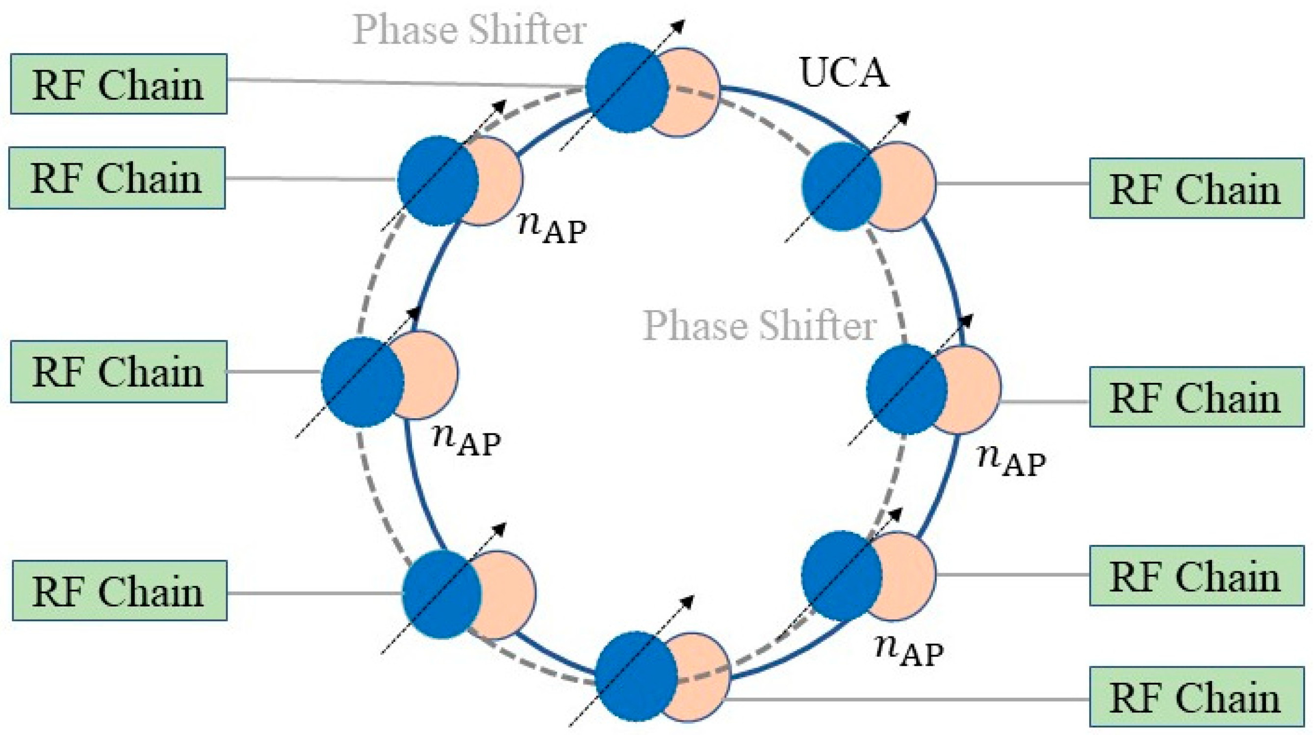
Consider , , …, M number of MSs served by , , …, E mmWave APs. The MSs use hybrid beamforming architectures for spatial multiplexeing, where the number of phase shifters is equal to the number of antennas in the UCA. Overall, the hybrid beamformer has few number of RF chains that connect multiple phase shifters and antennas (see Figure 1). The beamforming architecture is based on uniform circular array (UCA) of uniform antenna spacing, where each antenna is connected to a single phase shifter, then a limited number of RF chains feeds the UCA and phase shifters, i.e., enabling a hybrid beamformer as shown in Figure 1, where the solid ring represents the UCA and the dashed line is the array of phase shifters connected to the UCA. The UCA provides various advantages versus traditional uniform linear arrays (ULA), such as improved gains, narrower half power beamwidths (HPBW), reduced sidelobe levels (SLL), as well as 2D scanning capability, i.e., covering [0, 2π] spatial domain versus the 1D ULA covering [0, π], which needs back-to-back ULAs to cover [0, 2π]. Therefore, a reduced number of antennas is required to realize similar directivity and gain values, i.e., reduced power consumption. Additionally, UCA maintains fixed HPBW over all spatial direction, as opposed to ULA that suffers from the beam broadening effects near end-fire directions. Along these lines, this work adopts UCA for the hybrid beamforming design due to its better directivity and reduced power consumption, since the MS has limited input power (battery lifetime).
In light of the above, consider M MSs, each equipped with a UCA of total antenna elements that are equi-spaced on the x-y plane along a circular ring that has a radius, a. A group of adjacent antenna elements are combined together to form a single section , i.e., for s total number of sections. Each section s is then connected to a single RF chain, , to radiate a single beam in direction, specified by the array factor of the combining vector. Note here that the number of RF chains is equal to the number of sections in the hybrid beamformer, i.e., and ≪ . Overall, each MS radiates total number of simultaneous beams for spatial multiplexing with a single or multiple mmWave APs.
3.2. Digital Beamformer at the mmWave Fog APs
Digital beamforming architectures are used at the fog APs due to the abundant input power at the base band units (BBU) and radio remote heads (RRH). This is also necessary to support multi-user connectivity. Note that network function virtualization (NFV) can be utilized to separate the RRH from the BBU, see [16]. Hence consider , , …, E number of APs, each is equipped with a UCA composed of antennas that are equally spaced along circular ring. In contrast to the MS design, each antenna here, , is connected to one RF chain, . Note that the total number of antennas is equal to the number of RF chains, i.e., . Additionally, the overall radiated pattern from each RF chain is a unique data stream, hence enabling spatial multiplexing. The signal model between the MS and AP is now presented. This architecture is depicted in Figure 2.
3.3. Downlink Signal Model
Consider MSs operate in time-division duplexing (TDD) mode with APs, with reciprocal channel state information (CSI) knowledge at MSs and APs. The downlink received signal model in RF domain at the MS (analog section of the precoder) is modeled as,
where the variables H, z and w symbolize in order the complex channel, control signal (CS), and additive white Gaussian noise (AWGN), , with variance . Here the variable denotes the beamforming matrix at the AP. Moreover the received signal at the MS subsequent to the combiner section, , is expressed as,
where the variables and denote the transmitted signal power and the MS combiner, respectively, where includes baseband and analog combiners, such that . Furthermore, the instantaneous received signal, , at the MS due to beamforming and combining vectors, where , and , is written as,
In general, the poor scattering propagation nature at mmWave bands impose the use of geometric channel models, written as [4],
where the variable and in order denote the blockage path loss, the complex gain of the l-th path for L number of paths captured in K clusters. Note that path gains here are also assumed to be Rician-fading, i.e., , where represents the ratio between power in the first path and other paths that possess reduced power levels. Moreover, the variables and represent in order the response vectors that capture the channel at the AP and MS. Therefore the overall response vector for the beamformer at the MS is given by the RF precoding matrix and is computed by the periodic array factor for the UCA at azimuth and elevation pointing directions (directions of main lobe peak) for each section (similarly at the APs) as per [17],
where and Ω denote the amplitude excitation of the n-th antenna, and the wavenumber, i.e., , where λ is the wavelength, , here is the speed of light, and is the carrier frequency. Finally, is the phase shift for the n-th element at the MS.
3.4. Blockage Model
The use of blockage models is required to account for two main link states, which are LoS and NLoS. First, direct LoS link gains between MS and APs that exist in the absence of obstacles are considered as Rician-fading, whereas link gains at the presence of obstacles are considered as Rayleigh-fading. Therefore the blockage model here is expressed in terms of an Indicator function, , that account for the aforementioned fading levels each independently, in addition to the transition levels LoS-to-NLoS. Overall, this model is gauged by measuring the path loss components as a function of distance [18], i.e.,
where the indicator function specifies the link-blockage state, i.e., (x) = 1 iff x = 1, and 0 otherwise. Furthermore, and denote the LoS and NLoS path losses, respectively, expressed by [19],
where d, , and denote the distance between the AP and MS, close-in reference distance, and path loss exponents (PLE) for the LoS and NLoS links, respectively. Based on the above lines, when a LoS link is not impacted by blockage effects, then the NLoS term decays to zero. Also, the terms and ( in Equation (7) indicate the LoS and NLoS probabilities at distance d, where , here is the blockage parameter showing obstacles sizes and densities. Note that the LoS link length is measured by 1/. This key formulation concludes that the probability of denser obstacles increases with larger distance values, which in turn decreases .
4. DC-NC Beam Failure Recovery
The diversity coding scheme can be considered as a feed-forwarding error detection method for multiple disjoint paths in multi-link networks, where some of the links can be used for redundant transmission, whereas the other links are used for data transmission. Namely, the proposed method here transmits data packets on the primary links, and also used a protection link for them, as shown next.
The DC-NC scheme is adopted to recover link failure due to blockage, where no feedback is required in this scheme for the recovery process. As a result, this scheme enhances the energy consumption levels in the network, where the mmWave APs do not retransmit lost packets again once failure occurs. Hence links can be utilized for enhanced capacity and spectral efficiency. In the proposed scheme, when the packet fails to arrive to destination due to the link failure, the dropped packet can be recovered at instantaneous time after the detection using DC. Moreover, the throughput is further enhanced by using NC that combines packets by coding them and transmitting the output to the destination via various paths and links. Overall, the advantages of the two methods are merged here to generate a diversity coding and network coding (DC-NC) scheme [20]. Hence the proposed scheme enhances network reliability with very low latency in network recovery (restoration), in addition to magnified throughput. This scheme is applied here for mmWave link recovery, where the network is composed of multiple mmWave fog APs and single MS, as depicted in Figure 3. Note that extending network to a higher number of MSs is also possible.
The idea of DC-NC is now presented for a network portion of multiple mmWave APs composed of multiple wireless links, see Figure 3. First, consider that three packets , , and are transmitted on the primary links, and three coded packets , , and are also transmitted on the protection links. Note that data packets are initiated from the source AP nodes , , and are directly transmitted to the destination MS through AP nodes and , or indirectly through intermediate APs. In this scenario, and use their direct links with and to transmit , and respectively. Moreover, the DC-NC encoding AP receives , , and from , , and respectively and then it encodes them to compute three coded packets, denoted by , , and as follows [20],
where the parameters in aforementioned Equations (10)–(12) denote the parity generator matrix for , , and . These parameters are linearly independent to each other, therefore achieving matrix inversion. Also note that multiplication and addition operations here correspond to “AND” and “XOR” operations, respectively. The coded packets , , and are now transmitted to , , and respectively. Moreover, the throughput gains are obtained by transmitting through to and and through to AP destinations. The MS will receive and from APs and . Here decodes , , and and retrieves and as [20],
Now by substituting Equations (11)–(14) respectively, this results in,
Moreover, the aforementioned Equations (15) and (16) can be expressed in a matrix form as,
Furthermore, the variables and can be retrieved by applying matrix inversion, i.e.,
Note that the coefficients are constants and are known at all nodes. As a result, the destination node decodes , , and in a similar manner to retrieve and . Thereby, the throughput gains are significantly improved here (at approximately 20%) [19].
Note that the reliability of the network can be enhanced by transmitting from to all intermediate fog APs. However, one attribute for the DC-NC scheme is that when no blockage is present, then the AP(s) drops , whereas when a blockage-based link failure is present, as if the link between and is blocked and once realizes that a packet is lost, it then utilizes , , and in order to recover all packets , , and , written as,
Furthermore, the lost packets are recovered by computing matrix inversion, as
In addition, if or are lost at attributed to blockage effects on links, then , and ( or ) can still be recovered at in a similar manner to the aforementioned recovery procedure. Likewise, can recover the lost packets.
In light of the above, one link failure can be mitigated and packets can be recovered at each destination node using DC-NC scheme for mmWave communications. Moreover, three simultaneous link failures and packet drops can further be tolerated, one for each destination node. Note that only four protection links are used to improve the reliability of the network, i.e., by protecting it from single link failure at each destination node.
5. Performance Evaluation
The network settings include E = 9 fog APs incorporating DC-NC transmission scheme to the destination MS. The links between these APs are initially set to LoS settings and the received signal parameters are based on the channel gains and the path losses derived from the geometric channel models. The antenna elements are based on the rectangular microstrip patch antenna model with gains of 3–4 dBi for each antenna in the UCA. Here the digital beamformer at the AP is equipped with = 256 antennas, meanwhile the hybrid beamformer at the MS is composed of 128 antennas. The spacing between the antennas is set to half-wavelength to avoid grating lobes and mutual coupling. Moreover, the separation distances between the fog APs is set to 500 m, whereas the separation distances between the MS and the AP is set to 200 m. The channel at the MS is first set to LoS, where a high signal level is captured, composed of K = 4 clusters (each of L = 3–5 rays). Once blockage starts to appear, then the channel transits to NLoS and the received signal level starts to degrade, at which the received signal profile is composed of K = 2 clusters, each of L = 2–3 rays. These clusters contribute to the signals received from the secondary link once the primary link has failed. The proposed recovery scheme is now evaluated versus conventional recovery schemes using key performance metrics, i.e., recovery times and power levels.
5.1. Recovery Times
The recovery time (delay) at the MS is defined as the time duration needed to establish alternative new beamforming and combining vectors at the MS and AP, i.e., time required to recover lost data due to the failed links. This process is conducted in the case that the primary link associated with the optimum beamforming and combining vectors fails due to blockage effects. This time is calculated as (measured in microseconds), where the variables Q, and here denote the total number of signal measurements at various beamforming and combining vectors to determine the new directions, the primary synchronization signal (PSS) duration and number of RF chains at the MS, respectively. Figure 4 shows the access times for the proposed DC-NC recovery schemes versus key existing methods. Specifically, the proposed scheme yields very reduced delays at very high number of combining vectors. A key attribute for the proposed scheme is the instantaneous recovery times, where it only requires only the PSS duration (200 microseconds) to recover the lost data, since no beam measurements are needed here, hence beam scanning is not required here. Recovery times also feature similar levels regardless of the number of combining vectors. This is due to the fact that the redundant protection link can resolve the lost data instantly, when the signal affiliated with one of the primary beams fails due to blockage.
Meanwhile, existing schemes require scanning various spatial directions in order to specify the alternative optimum beamforming and combining vectors and recover data. In particular, the codebook-based iterative search, codebook-based metaheuristics search, and sidelobes exploitations schemes require in order 9500, 7000, and 4800 microseconds as compared to 200 microseconds only for the proposed DC-NC scheme when transmitting at 64 beams. Overall, the near-instantaneous times achieved here avoid connections drops, since it eliminates consuming scanning times that exceeds the channel coherence time.
5.2. Energy Consumption
The energy consumption, , at the MS presents a vital factor in the design of the RF transceivers, requirements for amplification, filtering and sampling at Gb/Sample rates. This value is gauged as the power consumption levels during which the MS is in recovery mode, i.e., power consumption, , during recovery times. In notations, = calculated as,
where , , , , , and denote the power consumption (in milliwatts) for the phase shifters (e.g., varactor-loaded transmission-line analog phase shifter), antenna elements (rectangular microstrip patch antenna), the low noise amplifier (LNA), RF chain, analog-to-digital converter (ADC), and the baseband combiner (BB). Also, , , , , , and denote the number of antennas and affiliated phase shifters at each codebook stage. Note that and are calculated respectively by [21],
where , , , , , , and B denote the power consumption for the mixer (MIX), local oscillator (LO), low pass filter (LPF), baseband amplifier (AMP), energy consumption per conversion in the ADC, sampling rate, and the total number of bits, respectively. The power consumption for the different components are also summarized in Table 1, as derived from studies in [21].
Overall, Figure 5 shows that the proposed scheme returns very favorable energy consumption levels as compared to major existing schemes. For example, for a codebook composed of 50 combining vectors (transmitting at pencil beam), the proposed scheme consumes 0.015 milliJoules, versus 0.47, 0.35, and 0.23 milliJoules for the codebook-based iterative search, codebook-based metaheuristics search, and sidelobes exploitations schemes, respectively.
6. Conclusions
In this paper, one of the few initial studies on the implementation of mmWave communications in multi-point fog access points is proposed. The work here considers directional transmission at the fog access points and mobile stations. Then, a novel recovery scheme is proposed for multi-point standalone mmWave communications that takes into account link blockage. The scheme is based on diversity and network coding techniques that yield near-instantaneous recovery times and efficient power and energy consumption levels versus traditional methods, such as the codebook-based iterative and metaheuristics search schemes, as well as sidelobes exploitation search method. Future efforts will investigate the applications of alternative recovery methods taking into account the effect of the users mobility and channel coherence times.
Funding
This work is funded by Deanship of Scientific Research at King Faisal University, under Nasher Track (grant number 186242).
Conflicts of Interest
The author declares no conflict of interest.
References
- Mesodiakaki, A.; Adelantado, F.; Antonopoulos, A.; Alonso, L.; Verikoukis, C. Energy and Spectrum Efficient User Association in 5G Heterogeneous Networks. In Proceedings of the IEEE 27th Annual International Symposium on Personal, Indoor, and Mobile Radio Communications (PIMRC), Valencia, Spain, 4–7 September 2016. [Google Scholar]
- Liu, J. Initial Access, Mobility, and User-Centric Multi-Beam Operation in 5G New Radio. IEEE Commun. Mag. 2018, 56, 35–41. [Google Scholar] [CrossRef]
- Huo, Y.; Dong, X.; Xu, W. 5G Cellular User Equipment: From Theory to Practical Hardware Design. IEEE Access 2017, 5, 13992–14010. [Google Scholar] [CrossRef]
- International Mobile Telecommunications. Minimum Requirements Related to Technical Performance for IMT-2020 Radio Interface. In ITU-R Study Group 5; ITU: Geneva, Switzerland, 2017; pp. 6–7. [Google Scholar]
- Chiang, M.; Zhang, T. Fog and IoT: An Overview of Research Opportunities. IEEE Internet Things J. 2016, 3, 854–864. [Google Scholar] [CrossRef]
- Kim, J.; Lee, W. Feasibility Study of 60 GHz Millimeter-Wave Technologies for Hyperconnected Fog Computing Applications. IEEE Internet Things J. 2017, 4, 1165–1173. [Google Scholar] [CrossRef]
- Jasim, M.; Ababneh, M.; Siasi, N.; Ghani, N. Hybrid Beamforming for Link Recovery in Millimeter Wave Communications. In Proceedings of the 2018 IEEE Wireless and Microwave Technology Conference (WAMICON), Clearwater, FL, USA, 9–10 April 2018. [Google Scholar]
- Alkhateeb, A.; El Ayach, O.; Leus, G.; Heath, R. Channel Estimation and Hybrid Precoding for Millimeter Wave Cellular Systems. IEEE J. Sel. Top. Signal Process. 2014, 8, 831–846. [Google Scholar] [CrossRef] [Green Version]
- Jasim, M.; Aldalbahi, A.; Khreishah, A.; Ghani, N. Hooke Jeeves Search Method for Initial Beam Access in 5G mmWave Cellular Networks. In Proceedings of the 2017 IEEE 28th Annual International Symposium on Personal, Indoor, and Mobile Radio Communications (PIMRC), Montreal, QC, Canada, 8–13 October 2017. [Google Scholar]
- Jasim, M.; Ghani, N. Generalized Pattern Search for Beam Discovery in Millimeter Wave Systems. In Proceedings of the 2017 IEEE 86th Vehicular Technology Conference (VTC-Fall), Toronto, ON, Canada, 24–27 September 2017. [Google Scholar]
- Gao, B.; Xiao, Z.; Zhang, C.; Su, L.; Jin, D.; Zeng, L. Double-Link Beam Tracking Against Human Blockage and Device Mobility for 60-GHz WLAN. In Proceedings of the 2014 IEEE Wireless Communications and Networking Conference (WCNC), Istanbul, Turkey, 6–9 April 2014. [Google Scholar]
- Jasim, M.; Aldalbahi, A. Diversity Coding for Instantaneous Link Recovery in Millimeter Wave Communications. In Proceedings of the 2018 IEEE International Symposium on Signal Processing and Information Technology (ISSPIT), Louisville, KY, USA, 6–8 December2018. [Google Scholar]
- Jasim, M.; Ghani, N. Sidelobe Exploitation for Beam Discovery in Line of Sight Millimeter Wave Systems. IEEE Wirel. Commun. Lett. 2018, 7, 234–237. [Google Scholar] [CrossRef]
- Sulieman, N.I.; Balevi, E.; Gitlin, R.D. Enhanced Diversity and Network Coded 5G Wireless Fog-Based Fronthaul Networks. In Proceedings of the IEEE 88th Vehicular Technology Conference (VTC2018-Fall), Chicago, IL, USA, 27–30 August 2018. [Google Scholar]
- Ayanoglu, E.; Gitlin, R.D.; Mazo, J.E. Diversity coding for transparent self-healing and fault-tolerant communication networks. IEEE Trans. Commun. 1993, 41, 1677–1686. [Google Scholar] [CrossRef]
- Siasi, N.; Sulieman, N.I.; Gitlin, R. Ultra-reliable NFV-Based 5G Networks Using Diversity and Network Coding. In Proceedings of the 2018 IEEE Wireless and Microwave Technology Conference (WAMICON), Clearwater, FL, USA, 9–10 April 2018. [Google Scholar]
- Balanis, C. Arrays: Linear, Planar and Circular. In Antenna Theory: Analysis and Design, 3rd ed.; John Wiley & Sons: Hoboken, NJ, USA, 2005; pp. 290–304. [Google Scholar]
- Bai, T.; Desai, V.; Heath, R. Millimeter Wave Cellular Channel Models for System Evaluation. In Proceedings of the 2014 International Conference on Computing, Networking and Communications (ICNC), Honolulu, HI, USA, 3–6 February 2014. [Google Scholar]
- Sun, S.; Rappaport, T.S.; Rangan, S.; Thomas, T.A.; Ghosh, A.; Kovacs, I.Z.; Rodriguez, I.; Koymen, O.; Partyak, A. Propagation Path Loss Models for 5G Urban Micro- and Macro-Cellular Scenarios. In Proceedings of the 2016 IEEE 83rd Vehicular Technology Conference (VTC2016-Spring), Nanjing, China, 15–18 May 2016. [Google Scholar]
- Sulieman, N.I.; Balevi, E.; Davaslioglu, K.; Gitlin, R.D. Diversity and Network Coded 5G Fronthaul Wireless Networks for Ultra Reliable and Low Latency Communications. In Proceedings of the 2017 IEEE 28th Annual International Symposium on Personal, Indoor, and Mobile Radio Communications (PIMRC), Montreal, QC, Canada, 8–13 October 2017. [Google Scholar]
- Akdeniz, M.R.; Liu, Y.; Samimi, M.K.; Sun, S.; Rangan, S.; Rappaport, T.S.; Erkip, E. Millimeter Wave Channel Modeling and Cellular Capacity Evaluation. IEEE J. Sel. Areas Commun. 2014, 32, 1164–1179. [Google Scholar] [CrossRef]
Figure 1.
Hybrid beamformer at the mobile station (MS).

Figure 2.
Digital beamformer at mmWave fog APs.

Figure 3.
MmWave fog access points network topology.

Figure 4.
Recovery times at different numbers of combining vectors.

Figure 5.
Energy consumption observed at different numbers of combining vectors.


Table 1.
Power Consumption values for the proposed scheme.
| Power Consumption Variable | Value (mWatt) |
|---|---|
| , , , , , , , , | 78, 5.4, 20, 20, 20, 19, 5, 14, 5 |
© 2019 by the author. Licensee MDPI, Basel, Switzerland. This article is an open access article distributed under the terms and conditions of the Creative Commons Attribution (CC BY) license (http://creativecommons.org/licenses/by/4.0/).
Share and Cite
MDPI and ACS Style
Aldalbahi, A. Link Recovery Scheme for Multi-Point mmWave Communications. Electronics 2020, 9, 50. https://doi.org/10.3390/electronics9010050
AMA Style
Aldalbahi A. Link Recovery Scheme for Multi-Point mmWave Communications. Electronics. 2020; 9(1):50. https://doi.org/10.3390/electronics9010050
Chicago/Turabian StyleAldalbahi, Adel. 2020. "Link Recovery Scheme for Multi-Point mmWave Communications" Electronics 9, no. 1: 50. https://doi.org/10.3390/electronics9010050
Note that from the first issue of 2016, this journal uses article numbers instead of page numbers. See further details here.