A New Method of Detecting and Interrupting High Impedance Faults by Specifying the Z-Source Breaker in DC Power Networks

1
Electrical and Computer Engineering, Old Dominion University, Norfolk, VA 23529, USA
2
Electrical and Computer Engineering, Mercer University, Macon, GA 31207, USA
*
Author to whom correspondence should be addressed.
Electronics 2020, 9(10), 1654; https://doi.org/10.3390/electronics9101654
Submission received: 12 September 2020
/
Revised: 4 October 2020
/
Accepted: 7 October 2020
/
Published: 11 October 2020
(This article belongs to the Section Power Electronics)
Abstract
:High impedance faults (HIFs) that cause a relatively smaller current magnitude compared to the traditional low impedance faults are not easily detectable but can cause an extreme threat to electric apparatus and system operation. This paper introduces a new method of detecting and interrupting HIFs in DC power networks by specifying Z-source circuit breakers (ZCBs). The ZCB is a protective device for high power DC branches, with the capabilities of protecting bidirectional power flow and automatic/controllable turnoff function. In this new method, the operational mode of ZCB (i.e., either the detection mode or interruption mode) can be specified. Beyond previous research, the theoretical analysis has been performed on this method and the mathematical relationship between the maximum HIF resistance and required Z-source capacitance has been derived and verified. It has been found that the ZCB can respond to a HIF accordingly when its capacitances are properly adjusted in the ZCB circuit. With the adjustment of these Z-source capacitances, the ZCB can be specified to detect and report a HIF status to power system operators, or cut off the HIF branch and protect the rest of the DC system directly. The new method can detect/interrupt a HIF that is as small as 2 times of its nominal rated current and the effectiveness and general usage of the derived equation have been verified by both low power experiments in lab and high power simulation tests.
1. Introduction
1.1. HIF Problem and Its Existing Solutions
Modern power systems have developed rapidly in the past few decades by integrating digital communication and sensing technologies that improve the efficiency, reliability, and control flexibility in electric power networks. Advanced technology and transmission/distribution automation have made the detection of previously unnoticeable disturbances possible. Over-current protection techniques can easily detect the traditional low-impedance faults that are caused by high conductivity elements. However, the real-time monitoring of high impedance faults (HIFs) and determining its location is still a challenge currently. For example, a HIF occurs in a medium voltage power system, when there is an electrical contact between an energized conductor and a highly resistive surface (such as sand, asphalt, tree branches, etc.) This results in the HIF remaining uncleared and exposes a person to a high risk of electric shock. It also possesses a threat to the livestock and can cause significant damages to properties through the possibility of fire hazards [1]. Besides traditional AC power systems, DC transmission and distribution systems develop fast in the past decades, with more integrated renewable energy resources in the DC format. Additionally, HIFs are still a challenging issue in the DC system. For example, in low-voltage DC system, the fault impedance is comparable to the nominal ratings sometimes. Additionally, the resulted low magnitude short circuit currents are responsible for the formation of electric arcs with the presence of high frequency contents [2]. Thus, the HIF condition in DC power systems should be detected and subsequently isolated to minimize any significant danger.
To overcome the problem of HIFs, manipulation and processing of voltage and current measurements during HIF conditions are used in most of the existing HIF detection techniques for power grids. A wavelet transform-based method decomposes a signal into different frequency bands and locations in time to extract and detect the HIF characteristics as introduced in [3,4]. A method of placing multiple smart meters across the power network for HIF detection was developed in [5]. Additionally, a short-time Fourier transform approach was proposed in [6], where the main harmonic components of the phase current are extracted to identify HIF occurrence. In Reference [7], the HIF can be detected by analyzing the waveform distortion with the solid electrical breakdown theory. Likewise, HIF condition in [8] was detected by using the quasi differential zero sequence protection to analyze the current zero-sequence root mean square (RMS) value on feeders. The high frequency current signal in [9] was injected into the grid to impose a voltage on its node and evaluate the change in impedance characteristics for HIF detection. Any possible low frequency oscillation can be monitored by optimally placing phasor measurement units (PMUs) in AC power networks [10]. Despite the wide variety of existing methods, due to the limitations such as a lack of versatility and improper defining of effective variables and associated limits, detection of HIF in a power system may remain unnoticed [11].
1.2. DC System and Protection
The DC power system is an important research trend in the modern power systems, with its advantages in large power supply radius, flexible and efficient power conversion, and high and reliable power quality. Attraction of DC microgrids has significantly increased in recent years due to its higher system efficiency, lower capital and operating cost, and easier integration of renewable and distributed energy resources [12]. Microgrids, automotive, renewable energy systems, and several other applications require a continuous demand of DC power flow from, to, or between its various energy storage elements. These applications need a bidirectional DC circuit breaker to ensure the protection and reliability of high-power DC branches. Fault protection due to the lack of zero-crossing point in the DC fault current is a challenging issue that constrains the widespread use of DC power networks.
Several solutions of DC protection have been proposed to resolve the arc problem in DC networks. For low voltage and medium voltage DC applications, oversized AC circuit breakers (ACCBs) are used as a simple solution. However, this solution reduces the efficiency of the ACCB and increases the cost if implemented on a large scale [13]. The fault characteristics of a DC power network are quite different from the one in a traditional AC network. Thus, conventional AC protection schemes are inapplicable to the DC power network [14]. Another option is applying the DC circuit breakers (DCCBs) based on fully-controlled semiconductor devices, such as metal-oxide-silicon field-effect transistors (MOSFETs), insulated-gate bipolar transistors (IGBTs), etc. [15]. However, the semiconductor-based DCCBs require additional tripping circuits for forced commutation, which increases the cost and complexity of the DCCBs. Additionally, the DCCBs have excessive power losses. In addition, for high voltage DC applications, various mechanical circuit breakers were introduced in [16,17,18] for DC fault clearance. “These mechanical DC breakers can only interrupt the fault current once and cannot achieve a second round of interruption if a DC fault needs permanent reclosing”. Additionally, different kinds of solid-state DCCBs [19], hybrid DCCBs [20], and power-electronic-based DCCBs [21,22,23,24] have been developed for high voltage DC systems.
1.3. ZCB and HIF Detection/Interruption Modes
To overcome the limitations of the traditional DCCBs, a new solid-state circuit breaker named the “Z-source Circuit Breaker (ZCB)” was introduced in [25], which can respond to and isolate DC faults according to its specification. The z-source circuit, firstly introduced in [26], could interface a voltage or current source to achieve a voltage boost utilizing the short-circuit state [27]. Later, this “z-source” concept found its application in DC circuit breakers, i.e., the ZCBs. A ZCB is based on the feature of zero-current closing in a thyristor, which provides a way of interrupting load-carrying currents. For operating the ZCB, a gate signal is initially applied to the thyristor until the z-source capacitors are fully charged up to the source voltage and a steady-state current is flowing through the z-source inductors. After that, the gate signal should be removed from the thyristor as the initial starting is completed and steady-state operation is achieved. From now on, the ZCB is armed to operate in response to fault conditions.
As of now, several topologies of ZCB have been introduced as the expansion and development of the first proposed ZCB from [25]. A modified Z-source breaker topology was introduced in [28] that uses a common return ground path to minimize the reflected fault current drawn from a source. The study of [29] represented a bidirectional ZCB (BZCB) with reduced peak source current and its low-pass filter frequency response characteristic. Likewise, another BZCB was designed in [30] by using coupled inductors for low voltage DC microgrid applications. A low loss ZCB with a single silicon controlled rectifier (SCR) was developed in [31], which improves the efficiency of power delivery in low voltage DC systems. Later, the on-state losses in ZCB was further reduced by adopting an ultrafast mechanical switch [32]. The reference [33] performed the analytical evaluation of system impedance during fault in a DC system including a group of power electronic devices. The operational power losses were compared among the several existing ZCB topologies in [34]. Based on our prior studies on ZCB topologies, the research of this paper is performed on the topology of the intercross connected bidirectional Z-source circuit breaker (ICC-BZCB) introduced in [35], because of its high efficiency.
In the protection study of DC power networks, many research works have been done. For example, the development and assessment of the DC fault protection strategy were introduced for the medium voltage integrated power systems [36]. Additionally, the application and protection scheme design of ZCB was designed for DC microgrids [37]. However, all of these studies dealt with the low impedance fault (LIF) cases, not the HIF case in this paper.
In this paper, a new method is proposed to specify the ICC-BZCB parameters to detect and interrupt HIFs. This enables a new function of ICC-BZCB. The proposed method can be easily integrated into a power network to handle HIF problems, and thus improves system reliability. The proposed method can identify HIF conditions by monitoring the status of Z-source capacitance when the ZCB is specified into the HIF detection mode (HD-Mode). Additionally, the ZCB can be specified into the HIF interruption mode (HI-Mode) by adjusting the Z-source capacitance properly, in order to interrupt the HIF freely. The HD-Mode is defined as the voltage oscillation on Z-source capacitances that demonstrates the HIF occurrence but no HIF interruption, whereas the HI-Mode is defined as the response of the ZCB to a HIF in order to cut it off. This is an easy and efficient way in the practical application to realize the HDM/HIM specification in ZCB. The feasibility of this new method was originally revealed in our prior study of [38]. Beyond that point, this paper introduces the theoretical analysis to the revealed, derives a mathematical relationship between the maximum HIF resistance and the required Z-source capacitances in ZCB, and verify its effectiveness with the original experiment tests in [38] and the new high power simulation tests first presented in this paper.
The following sections of this paper are organized as follows: Section 2 briefly introduces the topology and characteristics of ICC-BZCB; Section 3 describes the proposed method of specifying HIF detection and interruption for ZCB; Section 4 verifies the proposed method with simulation and experimental results and related analysis, which leads to a discussion and a conclusion drawn in Section 5 and Section 6.
2. Brief Introduction of “Intercross Connected Bidirectional Z-Source Breaker”
A ZCB typically consists of several power electronic components, including SCRs, diodes, and other passive devices, e.g., inductors and capacitors. Up to date, there are several ZCB topologies and their parameter specifications developed based on the principle of resonant circuit [28].
The HIF detection/interruption method studied in this research was based on the topology of ICC-BZCB as shown in Figure 1. This topology is highly efficient in power transferring and operates in a similar resonant behavior like other ZCB topologies. It simply consists of two SCRs (T1 and T2), two inductors (L1 and L2), three capacitors (C0, C1, and C2), and two diodes (D1 and D2), forming a bidirectional power route between the voltage source (Vs) and the DC load (RL + CL). The principle and feature of its bidirectional protection have been introduced in [35] in detail. The ICC-BZCB can interrupt fault currents in both directions, if there is a distributed energy recourse replacing the passive load branch in Figure 1.
3. Methodology of HIF Detection/Interruption with Z-Source Breaker
In this section, a new design methodology was described for component sizing and enabling HIF detection/interruption in ICC-BZCB. This methodology is presented on an example DC system of 240 V and 3 A. Initially, the ZCB parameters are preliminary designed for the DC system based on the method in [39] as listed in Table 1. The equations of the minimum detectable fault conductance, minimum required fault conductance ramp rate, and SCR tripping time from [35,39] were used here for parameter specification. With the parameters in Table 1, the ZCB can trigger any fault current higher than or equal to the minimum detectable fault current selected by us, which is two times of the rated load current, i.e., 2 × IL = 6 A.
The preliminary design was verified here. Figure 2 shows the operation of a ZCB with the specification of Table 1 for two different cases of fault current: Case I with a fault current IF = 5 A, which was less than twice the rated load current; and Case II with IF = 7 A, which was higher than twice the rated load current. It is observed that the breaker was irresponsive in Case I, whereas the fault current was cut off successfully in Case II [38]. This test proved the feasibility of control of ZCB’s responsive behavior to HIFs by specifying its parameters.
To freely control ZCB operating into the HD-Mode and HI-Mode, a new method was proposed by specifying the Z-source capacitances (CZCB) in this paper. In this method, all of the Z-source capacitances (i.e., C0, C1, and C2) increased proportionally and the relative responses of breaker to a HIF were measured. It has been found that, as the value of CZCB increased, the reverse current contribution of CZCB in responding to the HIF increased accordingly within the breaker. Figure 3 is obtained to represent the relationship between the fault resistance and the required Z-source capacitance to turn the SCR off under HIF conditions. As the value of CZCB increased, the minimum detectable fault conductance of the breaker became even smaller. Table 1 was used as the base values for the multiplication factor of CZCB in Figure 3 to specify and control HIF detection/interruption modes for ICC-BZCB.
From Figure 3, the maximum fault resistance that a breaker can trip under HIFs is derived as (1) by using the curve-fitting method. The equivalent circuit of ICC-BZCB right after the occurrence of fault is represented in Figure 4, which indicates the currents contributed for the SCR’s turnoff that are supplied by the Z-source capacitors. With the proper adjustments of Z-source capacitors, the ZCB is now enabled to handle a fault current from a HIF with even smaller conductance value.
where: RF-Max is the maximum fault resistance that a ZCB can trip independently (in Ω); RFault-Base is the base fault resistance (in Ω) as listed in Table 1; CZCB-Mul is the multiplication factor, by which the Z-source capacitors should be amplified on the preliminary design values listed in Table 1.
From the theoretical analysis, the current through the Z-source capacitor (C2) in terms of the fault current (iF) given in [35] can also be restructured for our proposed HIF detection/interruption control, as:
Combining (2) with the Equations of (3) and (4) (i.e., the Equations (1) and (5) in [35]), a modified equation for the minimum detectable fault conductance is derived here as (5):
where, Vs is the source voltage; Vf,SCR and Vf,Diode are the forward voltage of the SCR and the diode respectively; RLoad = load resistance, Ron,SCR = on-state SCR resistance, Ron,Diode = on-state diode resistance, and Rinductors = inductor resistance.
By comparing (1) and (5), both equations can introduce the same curve in Figure 3. However, the equation of (1) is much more convenient to be used than (5) for practical applications. Further, the post-fault behavior of ICC-BZCB is studied. During the initial moments of a fault, the total transient current of C0 and C1 are in the reverse direction of SCR’s prefault current [35], as shown in Figure 4. Thus, if magnitude of the sum of these reversely flowing currents (iC0 and iC1) is less than the holding current (iH) of the SCR, i.e., (iC0 + iC1) < iH, the SCR would not turn off and operates in the HIF detection mode. The holding current of SCR is the minimum anode current required to turn it off. The HIF can be detected by monitoring the discharging status of ZCB capacitance. In other words, if a HIF cannot motivate sufficient discharging from Z-source capacitors, the SCR would remain closed and thus the HIF might remain unnoticed and cause significant damages to electric devices in the system. In addition, the discharging amount is also proportional to the capacitance values of the Z-source capacitors. Therefore, the ICC-BZCB can be controlled and specified in either the HD-Mode or HI-Mode by adjusting Z-source capacitances, for HIF detection/interruptions.
To demonstrate the effect of Equation (1) for HIF detection/interruption, a simulation study is performed on the low power DC system of Table 1 in MATLAB/Simulink. In the simulation tests, the Z-source capacitances are adjusted along with a rise in fault resistance. All the breaker parameters applied are initially acquired from Table 1. The CZCB value is magnified by 1.0, 2.0, and 3.0 times, respectively. The updated values of CZCB for different multiplication factors are listed in Table 2. The fault resistance was set to: RF = 40 Ω, 50 Ω, and 60 Ω, respectively.
Figure 5 shows SCR currents for different RF values along with adjusted CZCB. RF-Max is the maximum fault resistance that a ZCB can trip independently. RF-Max can be calculated using (1): for CZCB-MUL = 2.0, RF-Max is calculated as 56 Ω, and for CZCB-MUL = 3.0 RF-Max is calculated as 61 Ω. Thus, as observed in Figure 5b, for CZCB-MUL = 2.0, the breaker successfully turned off for RF = 40 Ω and 50 Ω but was irresponsive to 60 Ω as this resistance value exceeded the maximum RF of for this case. However, for CZCB-MUL = 3.0, the maximum RF of could lead to three successful interruptions without failing since it is higher than all the three RF values. Thus, these tests verified the effectiveness of the proposed method by specifying ZCB’s HD-Mode/HI-Mode via (1). The proposed method is further verified via experiment tests on a low power testbed in lab and simulation tests on a high power testbed in Section 4, to prove its general usage in DC power networks.
4. Simulation and Experimental Results
This section demonstrated the simulation and experimental results to validate the effectiveness of the derived curve for HIF detection in Figure 3. At first, a low power experimental test was performed on a hardware testbed, to verify the related simulation study in Section 3. After that, a high power simulation test of 5 kV, 5 MW, which represents a high power resistive load, was performed in the Matlab/Simulink environment. Beyond the low power experiment, this high power simulation test is designed to prove the general usage of (1) in different system ratings, especially in an actual engineering system with high power.
4.1. Experimental Tests on a 180 W, 120 V Testbed
An ICC-BZCB experimental prototype was designed to verify the proposed HIF control of ZCB, as shown in Figure 6. The testbed was established according to the parameters listed in Table 1. When the power supply was 240 V and the ZCB was specified to the “HI-Mode” with our proposed method, the fault current could be successfully cut off, as shown in Figure 7. However, due to the limit of current rating of 5 A in the “Main DC Power Supply” and some cases performed in the “HD-Mode” intentionally, we had to perform these tests with a lower input voltage of 120 V, which resulted in the prefault SCR current of 1.5 A and maintained the uncontrolled fault currents under 4.5 A to protect the laboratory equipment. Be aware that the expected fault current was 9 A under 240 V power supply. Since the construction ZCB model and circuit connection in Figure 1 was similar to those occurring in a real system, the experiment could be scaled by applying the per-unit calculation, to reflect the phenomena in the real world accurately [40,41]. The values in Figure 3 and Equation (1) are all per-unit values, and the required CZCB and related RF can be scaled as (6).
where CZCB_real and RF_real are the required Z-source capacitance and related fault resistance in a real system, respectively; CZCB_per_unit and RF_per_unit are the required Z-source capacitance and related fault resistance determined from Figure 3 and Equation (1), respectively; and CZCB_base and RF_base are the required Z-source capacitance and related fault resistance that can be calculated from the ratings of a real system, respectively.
Three sets of an experimental test were performed on the testbed to verify effectiveness of the proposed method by adjusting the values of Z-source capacitances according to Figure 3 and (1). The CZCB was adjusted to 1.0, 2.0, and 4.0 times to their initial specified value in Table 1. During the experiments, a fault was emulated by an additional resistive branch, which is connected in series to a controlled IGBT as the “Fault Emulation Board”, as shown in Figure 6.
4.1.1. Test #1—“The Cases of Unity Multiplication Factor in CZCB, i.e., CAdj = 1.0 × CZCB”
In this test, we paid attention to the ZCB’s behavior in response to the fault current, while the fault resistance (RF) gradually increasing. This test was performed to verify the cases with the multiplication factor of 1.0. No other parameter changed, except CZCB.
As shown in Figure 8, the ZCB operated in the HI-Mode and the breaker cut the circuit off in the HIF cases of lower fault resistances, in the cases of 0.438 × RFault_Base = 35 Ω and 0.5 × RFault_Base = 40 Ω. However, for higher fault resistances (in the cases of 0.625 × RFault_Base = 50 Ω and 0.78 × RFault_Base = 62.5 Ω), the ZCB did not cut off the fault and stays in the HD-Mode. A HIF could be detected by monitoring the status of CZCB and reported to the power system operator. It matched the result of Figure 5a.
4.1.2. Test #2—“The Cases of Two-Times Multiplication Factor in CZCB, i.e., CAdj = 2.0 × CZCB”:
4.1.3. Test #3—“The Cases of Four-Times Multiplication Factor in CZCB, i.e., CAdj = 4.0 × CZCB”
In this test, the multiplication factor further increased to 4.0, and thus increased the boundary of the HI-Mode and HD-Mode to . Beyond Test #2, the boundary increased further and thus led to the breaker’s turnoff when the fault resistance was at the highest values: RF = 0.78 × RFault_Base = 62.5 Ω, as shown in Figure 10.
Table 3 summarizes the status of ZCB for different cases of HIFs with adjust CZCB values. These results proved the effectiveness of (1), and demonstrated the controllability of ZCB towards HIFs, which was enabled by adjusting CZCB values properly.
4.2. Simulation Tests of a 5 MW, 5 kV Case
To prove the general usage of (1), a 5 MW, 5 kV case representing a high power resistive load was studied in the MATLAB/Simulink environment. The parameters of the simulation system are listed in Table 4. The fault resistance was gradually increased and a response of the ZCB to this varying fault current was observed.
Here, by analyzing peak currents through the capacitors, the effectiveness of the proposed method was numerically validated here. As stated earlier in Section 2, “During initial moments of a fault, the total transient current of C0 and C1 are in the reverse direction of SCR’s pre-fault current”. Thus, in order to ensure the SCR to commutate off naturally, the magnitude of the sum of iC0 and iC1 should be higher than the magnitude of the rated current of SCR at the prefault, which was 1 kA in this test. Figure 11 shows the transient currents of the Z-source capacitors (C0, C1, and C2) and the load capacitor (CL) were measured under different HIF resistances, which will be used in the performance analysis of the ZCB control towards HIFs later.
Further, the peaks of transient currents in CZCB were measured in the tests with a gradual increment of the fault resistance within [3 Ω, 4.5 Ω], as listed in Table 5. It is observed that the smaller fault resistance resulted in the higher peak of transient current. In the column of “iC0 + iC1 (A)” in Table 5, the red highlights represent the failed turnoff, while the green highlights representing the successful turnoff. From Table 5, for the case with CZCB-Mul = 1.0, the sums of transient Z-source currents were all less than the rated SCR current of 1 kA, as highlighted in red. Thus, the SCR did not commutate off. Compared to this case, with the adjusted CZCB (i.e., 3.0, 7.0, and 9.0 times), the sum of transient Z-source currents increased proportional to CZCB-MUL. The SCR commutated off naturally for RF = 3 Ω and 3.5 Ω, for CZCB-Mul = 3.0. Likewise, it turned off for RF = 3 Ω, 3.5 Ω, and 4.0 Ω for CZCB-Mul = 7.0, and finally turned off for all the case of RF with CZCB-Mul = 9.0, as highlighted in green. Figure 12 shows the waveform of voltages and currents for different ZCB components when the CZCB-MUL was equal to 1.0 and 9.0, respectively.
The result of Table 5 proved the effectiveness of using (1) to specify the HI-Mode/HI-Mode for ZCB in another high power case. It also verified the general usage of (1) for the proposed method of specifying ZCBs for HIF detection and interruption.
5. Discussion
It is observed in Figure 3 that the curve closed to its knee and thus the effect of this justification gradually went into saturation. So, the effective region was [0, 10] in the multiplication factor of CZCB, for this method. Fortunately, for many power engineering standards and applications, the system operated in the overload condition and did not need a circuit cutoff, when the RF was higher than 1.0 per unit. Therefore, the proposed method could be applied to general HIF conditions.
From the laboratory experiments of test A, we generated a zoomed-in figure as Figure 13 to show the effectiveness of identifying HIF conditions clearly. The mark “X” refers to the ZCB operating in the HD-Mode, and the mark “O” refers to the operation of ZCB in the HI-Mode. It can be observed that the “X” marks were separated from the “O” marks by the derived curve in the figure. Hence, Figure 13 proves the effectiveness and accuracy of the proposed method experimentally. Together, the tests in Section 4.1 and Section 4.2 proved the general usage of (1) in the engineering practice for the proposed method.
6. Conclusions
To overcome the HIF problems in DC power networks, a new method was developed to specify ZCBs to operate in either the HI-Mode for HIF interruption or the HD-Mode for HIF detection and reporting. The specification of ZCB is enabled by adjusting the Z-source capacitors properly. Beyond the feasibility of HIF detection revealed in [38], this paper conducted comprehensive analysis on the Z-source capacitance specification and derived a mathematical relationship between the maximum HIF resistance and required Z-source capacitance with enhanced verification tests. The derived equation has been verified by the circuit analysis and parameter specification methods. Further, the effectiveness and general usage of the derived equation have been validated in two different DC systems: a low power experimental testbed and a high power simulation system. The numerical analysis in Table 5 further proved the theoretical analysis of Z-source specification for HIF detection. The new method could detect/interrupt a HIF that was as small as 2 times of its nominal rated current. The method enables the HIF detection in DC power networks and is easy to be implemented in modern DC power systems to enhance their controllability and reliability in protection.
Author Contributions
Conceptualization, R.F. and Y.Z.; methodology, Y.Z.; software, S.B.; validation, S.B. and Y.Z.; formal analysis, S.B., R.F. and Y.Z.; investigation, S.B. and Y.Z.; resources, Y.Z.; data curation, S.B.; writing—original draft preparation, S.B.; writing—review and editing, R.F. and Y.Z.; visualization, S.B.; supervision, Y.Z.; project administration, Y.Z.; funding acquisition, Y.Z. All authors have read and agreed to the published version of the manuscript.
Funding
This research received no external funding. The APC was funded by the Department of Electrical and Computer Engineering at the Old Dominion University.
Conflicts of Interest
The authors declare no conflict of interest.
References
- Laaksonen, H.; Hovila, P. Method for high-impedance fault detection. CIRED Open Access Proc. J. 2017, 2017, 1295–1299. [Google Scholar] [CrossRef]
- Gomes, D.P.; Ozansoy, C.; Ulhaq, A. High-sensitivity vegetation high-impedance fault detection based on signal’s high-frequency contents. IEEE Trans. Power Deliv. 2018, 33, 1398–1407. [Google Scholar] [CrossRef]
- Santos, W.; Lopes, F.; Brito, N.; Souza, B. High-impedance fault identification on distribution networks. IEEE Trans. Power Deliv. 2016, 32, 23–32. [Google Scholar] [CrossRef]
- Chen, J.; Phung, T.; Blackburn, T.; Ambikairajah, E.; Zhang, D. Detection of high impedance faults using current transformers for sensing and identification based on features extracted using wavelet transform. IET Gener. Transm. Distrib. 2016, 10, 2990–2998. [Google Scholar] [CrossRef]
- Vieira, F.L.; Filho, M.J.; Silveira, P.M.; Guerrero, C.A.; Leite, M.P. High impedance fault detection and location in distribution networks using smart meters. In Proceedings of the 2018 18th International Conference on Harmonics and Quality of Power (ICHQP), Ljubljana, Slovenia, 13–16 May 2018; pp. 1–6. [Google Scholar]
- Lima, É.M.; Junqueira, C.M.D.S.; Brito, N.S.D.; de Souza, B.A.; Coelho, R.D.; de Medeiros, H.G.M.S. High impedance fault detection method based on the short-time Fourier transform. IET Gener. Transm. Distrib. 2018, 12, 2577–2584. [Google Scholar] [CrossRef]
- Wang, B.; Geng, J.; Dong, X. High-Impedance Fault Detection Based on Nonlinear Voltage–Current Characteristic Profile Identification. IEEE Trans. Smart Grid 2016, 9, 3783–3791. [Google Scholar] [CrossRef]
- Vianna, J.T.A.; Araujo, L.R.; Penido, D.R.R. High impedance fault area location in distribution systems based on current zero sequence component. IEEE Lat. Am. Trans. 2016, 14, 759–766. [Google Scholar] [CrossRef]
- Pasdar, A.M.; Sozer, Y.; Husain, I. Detecting and locating faulty nodes in smart grids based on high frequency signal injection. IEEE Trans. Smart Grid 2013, 4, 1067–1075. [Google Scholar] [CrossRef]
- Arabi, S.; Taheri, P.; Feng, Z.; Conto, J.; Huang, F. Best Locations for Low Frequency Oscillation Monitoring by PMUs. In Proceedings of the 2015 CIGRÉ Canada Conference, Winnipeg, MB, Canada, 31 August–2 September 2015. [Google Scholar]
- de Ferreira, G.; Assis, T.M.L. A Novel High Impedance Arcing Fault Detection Based on the Discrete Wavelet Transform for Smart Distribution Grids. In Proceedings of the 2019 IEEE PES Innovative Smart Grid Technologies Conference-Latin America (ISGT Latin America), Gramado, Brazil, 15–18 September 2019; pp. 1–6. [Google Scholar]
- Dragičević, T.; Lu, X.; Vasquez, J.C.; Guerrero, J.M. DC microgrids—Part I: A review of control strategies and stabilization techniques. IEEE Trans. Power Electron. 2015, 31, 4876–4891. [Google Scholar]
- Liljestrand, L.; Backman, M.; Jonsson, L.; Dullni, E.; Riva, M. Medium voltage DC vacuum circuit breaker. In Proceedings of the 2015 3rd International Conference on Electric Power Equipment – Switching Technology (ICEPE-ST), Busan, Korea, 25–28 October 2015; pp. 495–500. [Google Scholar]
- Jing, G.; Zhang, A.; Zhang, H. Review on DC Distribution Network Protection Technology with Distributed Power Supply. In Proceedings of the 2018 Chinese Automation Congress (CAC), Xi’an, China, 30 November–2 December 2018; pp. 3583–3586. [Google Scholar]
- Shen, Z.J.; Miao, Z.; Roshandeh, A.M. Solid state circuit breakers for DC micrgrids: Current status and future trends in DC Microgrids (ICDCM). In Proceedings of the 2015 IEEE First International Conference on DC Microgrids (ICDCM), Atlanta, GA, USA, 7–10 June 2015; pp. 228–233. [Google Scholar]
- Tokuyama, S.; Arimatsu, K.; Yoshioka, Y.; Kato, Y.; Hirata, K. Development and interrupting tests on 250kV 8kA HVDC circuit breaker. IEEE Power Eng. Rev. 1985, PER-5, 42–43. [Google Scholar] [CrossRef]
- Eriksson, T.; Backman, M.; Halen, S. A Low Loss Mechanical HVDC Breaker for HVDC Grid Applications; Proc. Cigré Session: Paris, France, 2014. [Google Scholar]
- Shi, Z.; Zhang, Y.; Jia, S.; Song, X.; Wang, L.; Chen, M. Design and numerical investigation of a HVDC vacuum switch based on artificial current zero. IEEE Trans. Dielectr. Electr. Insul. 2015, 22, 135–141. [Google Scholar] [CrossRef]
- Novello, L.; Gaio, E.; Piovan, R. Feasibility study of a hybrid mechanical-static dc circuit breaker for superconducting magnet protection. IEEE Trans. Appl. Supercond. 2009, 19, 76–83. [Google Scholar] [CrossRef]
- Meyer, C.; Schroder, S.; de Doncker, R.W. Solid-state circuit breakers and current limiters for medium-voltage systems having distributed power systems. IEEE Trans. Power Electron. 2004, 19, 1333–1340. [Google Scholar] [CrossRef]
- Zhan, C.; Smith, C.; Crane, A.; Bullock, A.; Grieve, D. DC transmission and distribution system for a large offshore wind farm. In Proceedings of the 9th IET International Conference on AC and DC Power Transmission (ACDC 2010), London, UK, 19–21 October 2010. [Google Scholar]
- Jovcic, D.; Wu, B. Fast fault current interruption on high-power DC networks. In Proceedings of the IEEE PES General Meeting, Providence, RI, USA, 25–29 July 2010; pp. 1–6. [Google Scholar]
- Cairoli, P.; Kondratiev, I.; Dougal, R.A. Coordinated control of the bus tie switches and power supply converters for fault protection in DC microgrids. IEEE Trans. Power Electron. 2012, 28, 2037–2047. [Google Scholar] [CrossRef]
- Hajian, M.; Jovcic, D.; Wu, B. Evaluation of semiconductor based methods for fault isolation on high voltage DC grids. IEEE Trans. Smart Grid 2013, 4, 1171–1179. [Google Scholar] [CrossRef]
- Corzine, K.A.; Ashton, R.W. A new Z-source DC circuit breaker. IEEE Trans. Power Electron. 2012, 27, 2796–2804. [Google Scholar] [CrossRef]
- Peng, F.Z. Z-source inverters. In Wiley Encyclopedia of Electrical and Electronics Engineering; Wiley: Hoboken, NJ, USA, 1999; pp. 1–11. [Google Scholar]
- Gajanayake, C.J.; Luo, F.L.; Gooi, H.B.; So, P.L.; Siow, L.K. Extended-boost $ Z $-source inverters. IEEE Trans. Power Electron. 2010, 25, 2642–2652. [Google Scholar] [CrossRef]
- Chang, A.H.; Sennett, B.R.; Avestruz, A.-T.; Leeb, S.B.; Kirtley, J.L. Analysis and design of DC system protection using Z-source circuit breaker. IEEE Trans. Power Electron. 2016, 31, 1036–1049. [Google Scholar] [CrossRef]
- Ryan, D.J.; Torresan, H.D.; Bahrani, B. A Bidirectional Series Z-Source Circuit Breaker. IEEE Trans. Power Electron. 2017, 33, 7609–7621. [Google Scholar] [CrossRef]
- Savaliya, S.G.; Fernandes, B.G. Analysis and Experimental Validation of Bidirectional Z-Source DC Circuit Breakers. IEEE Trans. Ind. Electron. 2019, 67, 4613–4622. [Google Scholar] [CrossRef]
- Yang, Y.; Huang, C. A Low-Loss Z-Source Circuit Breaker for LVDC Systems. IEEE J. Emerg. Sel. Top. Power Electron. 2020. [Google Scholar] [CrossRef]
- Mackey, L.; Rachi, M.R.K.; Peng, C.; Husain, I. Optimization and Control of a Z-Source, Ultrafast Mechanically Switched, High-Efficiency DC Circuit Breaker. IEEE Trans. Ind. Appl. 2020, 56, 2871–2879. [Google Scholar] [CrossRef]
- Jia, K.; Zhao, Q.; Feng, T.; Bi, T. Distance Protection Scheme for DC Distribution Systems Based on the High Frequency Characteristics of Faults. IEEE Trans. Power Deliv. 2019, 35, 234–243. [Google Scholar] [CrossRef]
- Bhatta, S.; Zhang, Y.; Fu, R. Comparative Analysis of Power Loss Associated with Topology of Bi-Directional Z-Source Circuit Breakers. In Proceedings of the SoutheastCon 2018, St. Petersburg, FL, USA, 19–22 April 2018; pp. 1–5. [Google Scholar]
- Keshavarzi, D.; Ghanbari, T.; Farjah, E. A Z-Source-Based Bidirectional DC Circuit Breaker with Fault Current Limitation and Interruption Capabilities. IEEE Trans. Power Electron. 2017, 32, 6813–6822. [Google Scholar] [CrossRef]
- Shah, S.I.A.; Batool, M.; Khaliq, A.; Nawaz, F. DC Fault Protection Strategy for Medium Voltage Integrated Power System: Development and Assessment. Arab. J. Sci. Eng. 2018, 43, 2859–2872. [Google Scholar] [CrossRef]
- Maqsood, A. Z-Source Circuit Breaker Design and Protection Schemes for DC Micro Grid Systems. Master’s Thesis, Electrical Engineering, Clemson University, Clemson, SC, USA, May 2017. [Google Scholar]
- Bhatta, S.; Zhang, Y.; Fu, R. Detecting High-Impedance Fault with Z-Source Circuit Breakers in Smart Grids. In Proceedings of the 2020 IEEE Applied Power Electronics Conference and Exposition (APEC), New Orleans, LA, USA, 15–19 March 2020; pp. 1755–1761. [Google Scholar]
- Bhatta, S.; Zhang, Y.; Fu, R. Relationship of Steady-State Power Loss and Configurable Tripping Time in Z-Source Circuit Breakers. In Proceedings of the 2019 IEEE Applied Power Electronics Conference and Exposition (APEC), Anaheim, CA, USA, 17–21 March 2019; pp. 3483–3489. [Google Scholar]
- Frentzel, R. Use of Similarity Relations in the Analysis of Lightning-Induced Transient Phenomena. Eur. Trans. Electr. Power 1997, 7, 173–177. [Google Scholar] [CrossRef]
- Gharagozloo, P.T. Power Transmission Lines Transient Electromagnetic Fields—A Study of Scale Modeling and the Effects of Ground Loss. Master’s Thesis, Electrical and Computer Engineering, University of Manitoba, Winnipeg, MB, Canada, 2009. [Google Scholar]
Figure 1.
Components and circuit connection of intercross connected bidirectional Z-source circuit breaker (ICC-BZCB).
Figure 1.
Components and circuit connection of intercross connected bidirectional Z-source circuit breaker (ICC-BZCB).

Figure 2.
Silicon controlled rectifier (SCR) currents of ZCB in two different cases of fault current, to prove the feasibility of the ZCB control.
Figure 2.
Silicon controlled rectifier (SCR) currents of ZCB in two different cases of fault current, to prove the feasibility of the ZCB control.

Figure 3.
Graph of the RF limit in response to the multiplication factor in CZCB, for high impedance fault (HIF) detection/interruption specification in ICC-BZCB.
Figure 3.
Graph of the RF limit in response to the multiplication factor in CZCB, for high impedance fault (HIF) detection/interruption specification in ICC-BZCB.
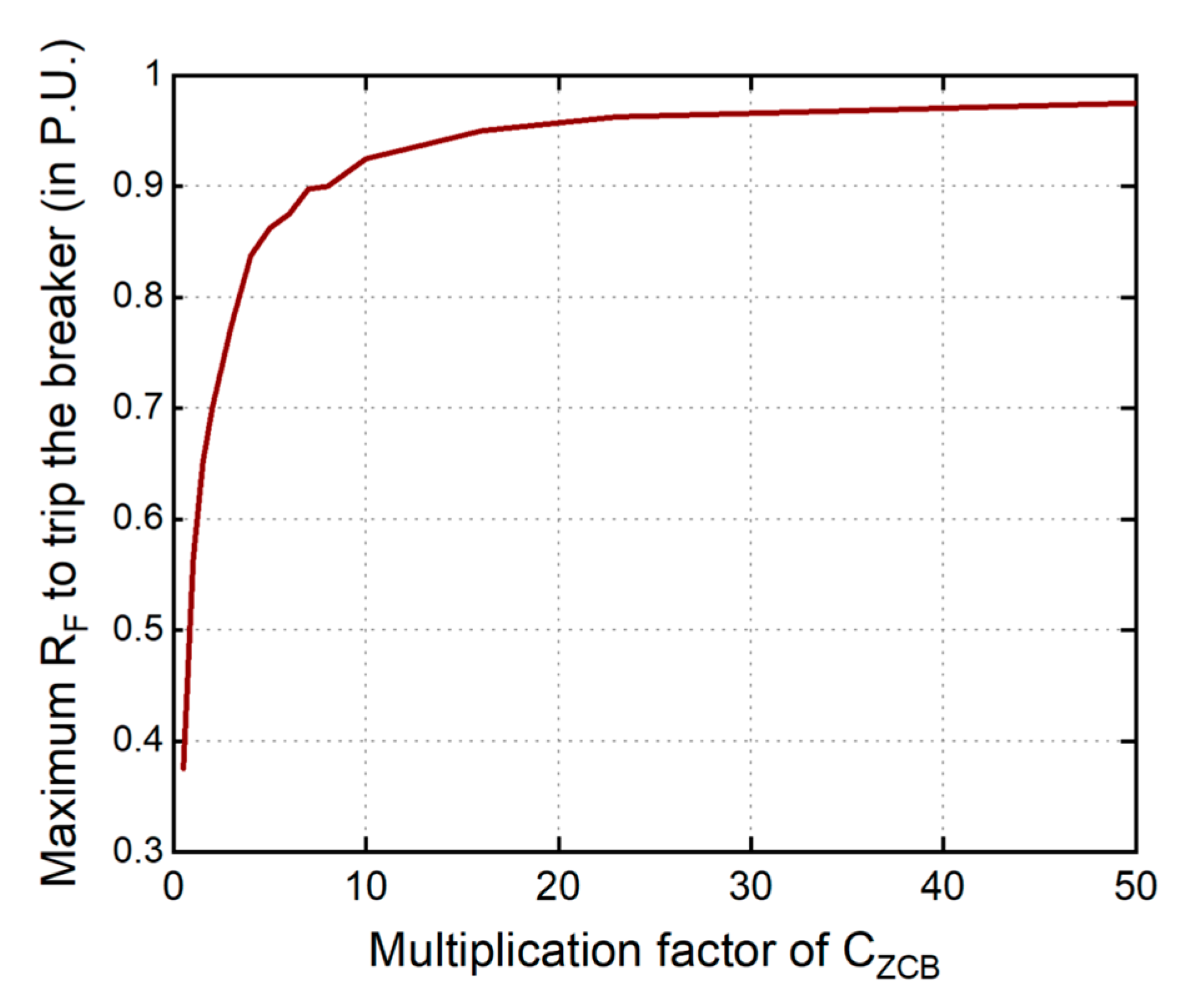
Figure 4.
Equivalent circuit of ZCB for the current analysis during the initial instance of fault.
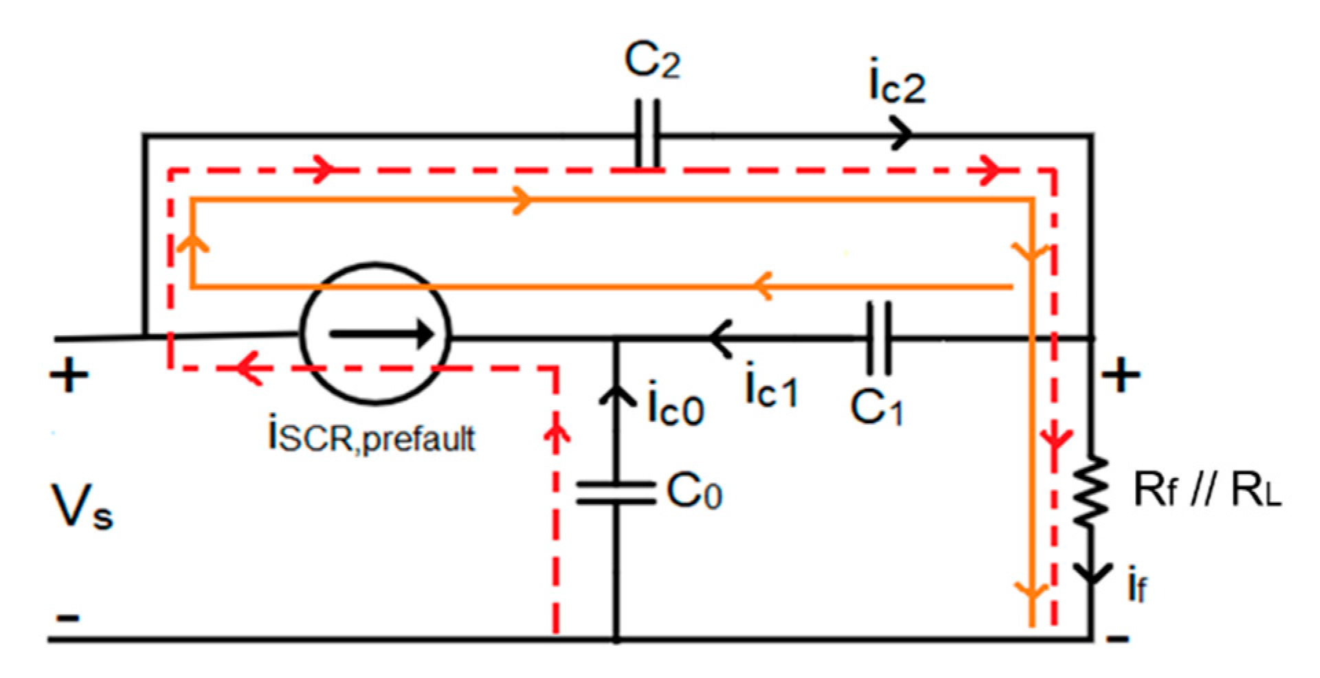
Figure 5.
Three simulation tests to verify (1) with CZCB-Mul = 1.0, 2.0, and 3.0 times. (a) SCR currents under the condition of CZCB-Mul = 1.0. (b) SCR currents under the condition of CZCB-Mul = 2.0. (c) SCR currents under the condition of CZCB-Mul = 3.0.
Figure 5.
Three simulation tests to verify (1) with CZCB-Mul = 1.0, 2.0, and 3.0 times. (a) SCR currents under the condition of CZCB-Mul = 1.0. (b) SCR currents under the condition of CZCB-Mul = 2.0. (c) SCR currents under the condition of CZCB-Mul = 3.0.

Figure 6.
The layout of the ICC-BZCB prototype and its connections to laboratory equipment.

Figure 7.
A fault current of 3 A cutoff under 240 V power supply (SCR current, in blue dashed line; fault tripping signal, in red solid line).
Figure 7.
A fault current of 3 A cutoff under 240 V power supply (SCR current, in blue dashed line; fault tripping signal, in red solid line).

Figure 8.
The ZCB’s cutoff behavior in the cases of the unity multiplication factor.

Figure 9.
The ZCB’s cutoff behavior in the cases of the two-times multiplication factor.
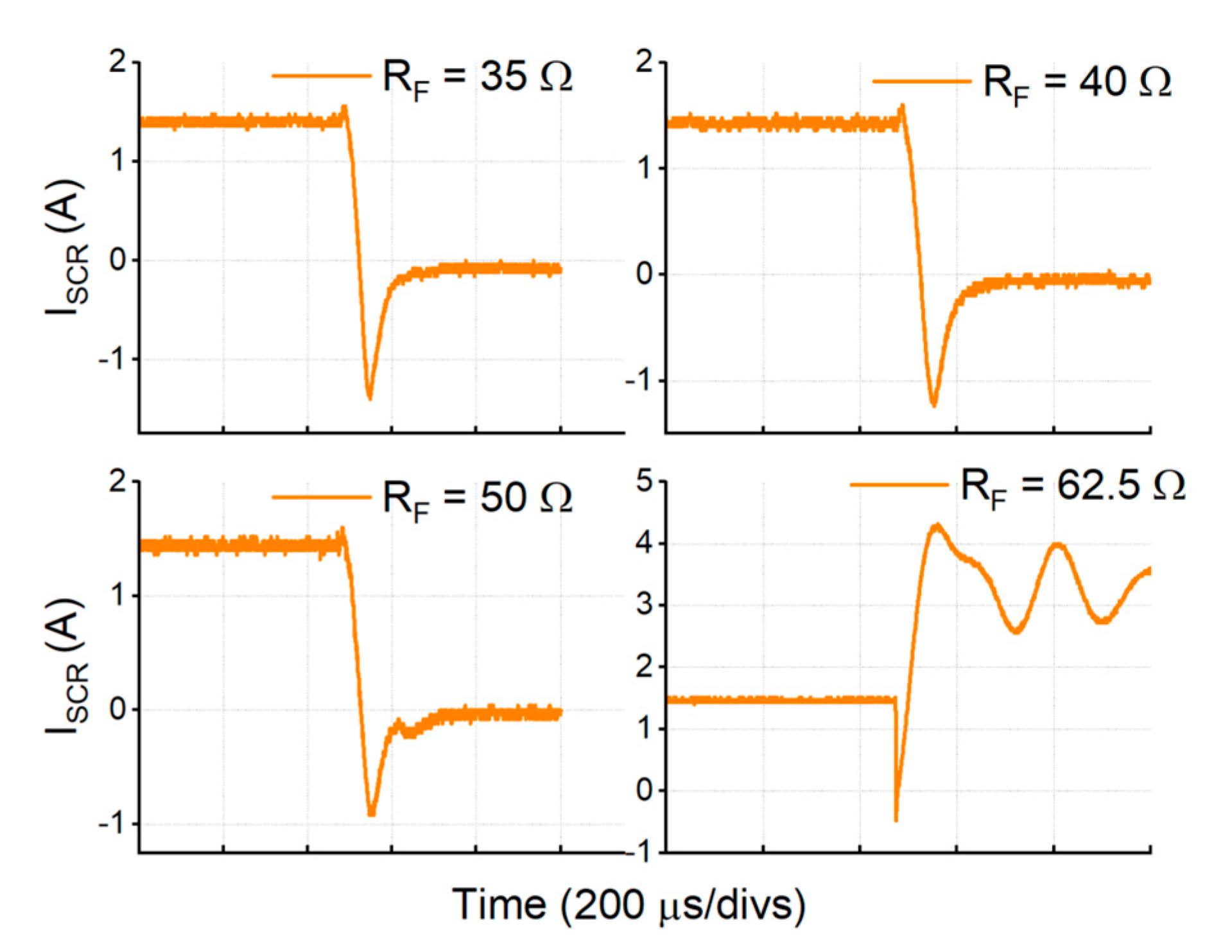
Figure 10.
The ZCB’s cutoff behavior in the cases of the four-times multiplication factor.
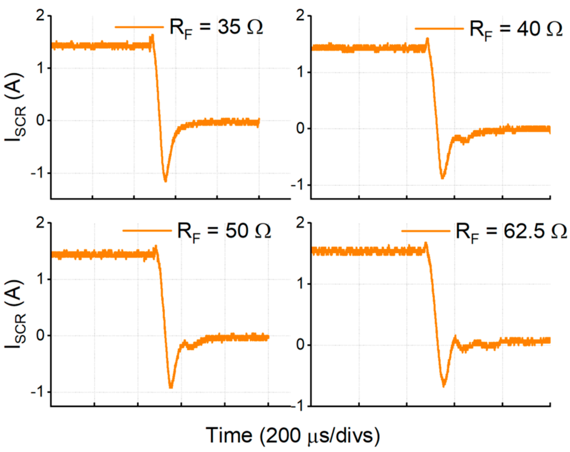
Figure 11.
Example of transient current measurements under different HIF resistances, with CZCB-Mul = 1.0. (a) Transient current through C0 and C1. (b) Transient current through C2 and CL.
Figure 11.
Example of transient current measurements under different HIF resistances, with CZCB-Mul = 1.0. (a) Transient current through C0 and C1. (b) Transient current through C2 and CL.
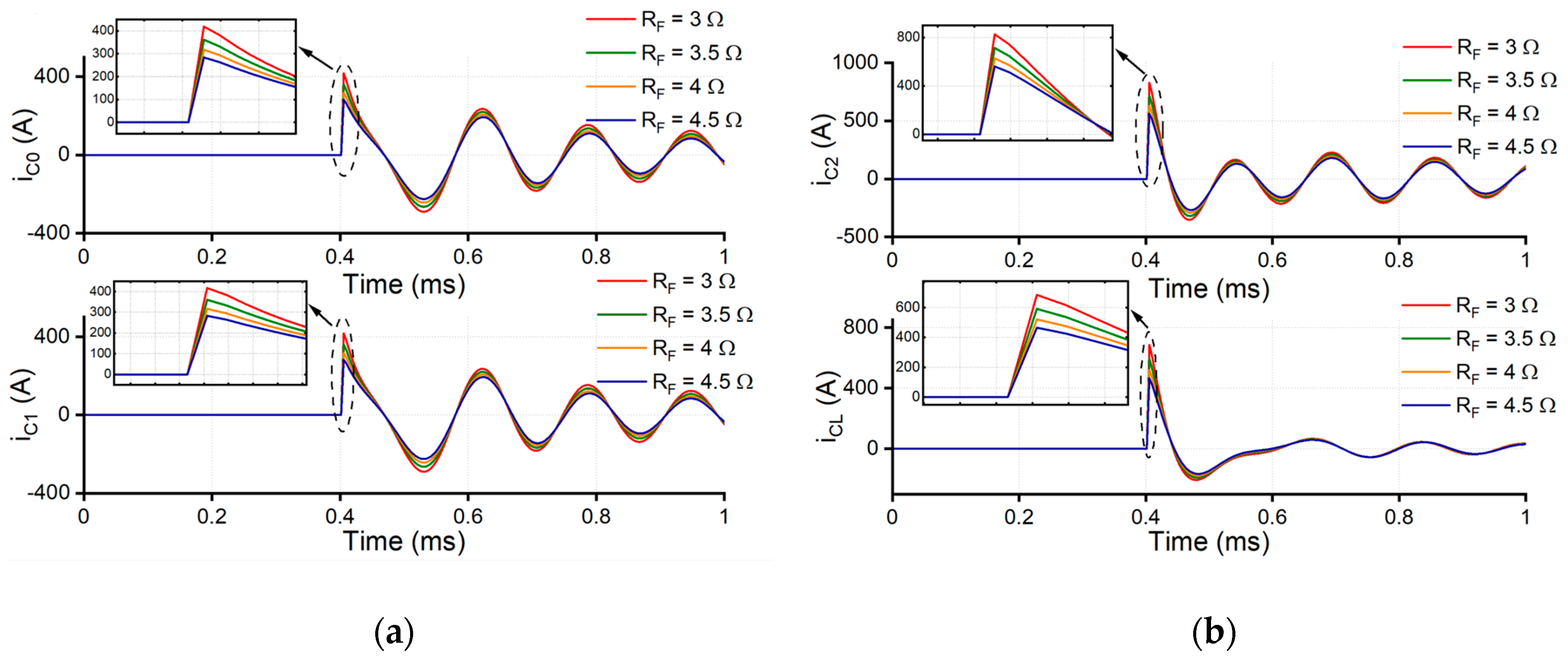
Figure 12.
Simulation waveforms of featured components in the ZCB circuit. (a) Current and voltage of SCR. (b) Current and voltage of load. (c) Transient currents (iC0 + iC1) and (iC2 + iCL). (d) Current and voltage of diode D2. (e) Current of inductor L1 and L2. (f) Voltage across inductor L1 and L2.

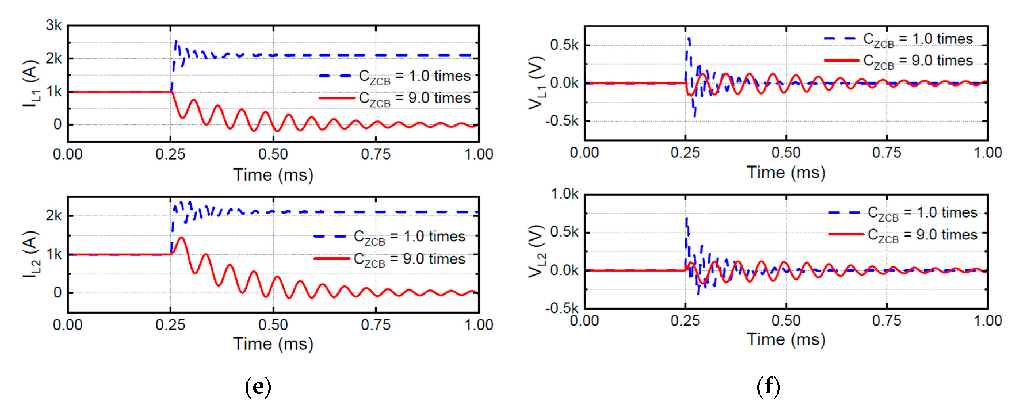
Figure 13.
A zoomed-in effective region of Figure 3, with specified HIF conditions.
Figure 13.
A zoomed-in effective region of Figure 3, with specified HIF conditions.


Table 1.
Z-source circuit breaker (ZCB) parameter specification from preliminary design.
| Parameter | Remark | Value |
|---|---|---|
| C1 = C2 = C0 = CZCB | Z-source capacitors | 2.2 µF |
| L1 = L2 = LZCB | Z-source inductors | 1.23 mH |
| CLoad | Load capacitor | 1.26 µF |
| VSource | Source voltage | 240 V |
| IL | Load current | 3 A |
| PL | Load power | 720 W |
| RL | Load resistance | 80 Ω |
| RFault_Base | Fault resistance base | 80 Ω |
| tq | SCR tripping time | 10 µs |
Table 2.
Adjusted CZCB values according to different CZCB-Mul.
| Base CZCB (µF) | CZCB-New = CZCB-Mul * CZCB (µF) | |||
| CZCB-MUL | 1.0 | 2.0 | 3.0 | |
| 2.2 | CZCB-New | 2.2 | 4.4 | 6.6 |
Table 3.
Summary of ZCB’s status in three experiments.
| RF (in Ω) | ZCB Status | ||
|---|---|---|---|
| CZCB = 1.0 | CZCB = 2.0 | CZCB = 4.0 | |
| 35 Ω and 40 Ω | OFF | OFF | OFF |
| 50 Ω | ON | OFF | OFF |
| 62.5 Ω | ON | ON | OFF |
Table 4.
Specified parameters of the simulation system.
| Parameter | Remark | Value |
|---|---|---|
| C1 = C2 = C0 = CZCB | Z-source capacitors | 36.92 µF |
| L1 = L2 = LZCB | Z-source inductors | 76.9 µH |
| CLoad | Load capacitor | 20.25 µF |
| VSource | Source voltage | 5000 V |
| RLoad | Load resistance | 5 Ω |
| RFault_base | Fault resistance base | 5 Ω |
| PLoad | Max. Load Power | 5 MW |
| tq | SCR tripping time | 10 µs |
Table 5.
Transient current and fault resistance analysis.
| RF (Ω) | CZCB-MUL | iC0 (A) | iC1 (A) | iC0 + iC1 (A) |
|---|---|---|---|---|
| 3 | 1.0 | 418 | 417 | 835 |
| 3.5 | 362 | 361 | 723 | |
| 4 | 318 | 318 | 636 | |
| 4.5 | 283 | 284 | 567 | |
| 3 | 3.0 | 755 | 755 | 1510 |
| 3.5 | 704 | 704 | 1408 | |
| 4 | 474 | 472 | 946 | |
| 4.5 | 419 | 417 | 836 | |
| 3 | 7.0 | 851 | 851 | 1702 |
| 3.5 | 790 | 790 | 1580 | |
| 4 | 743 | 743 | 1486 | |
| 4.5 | 492 | 482 | 974 | |
| 3 | 9.0 | 875 | 876 | 1751 |
| 3.5 | 813 | 812 | 1625 | |
| 4 | 762 | 763 | 1525 | |
| 4.5 | 723 | 722 | 1445 |
© 2020 by the authors. Licensee MDPI, Basel, Switzerland. This article is an open access article distributed under the terms and conditions of the Creative Commons Attribution (CC BY) license (http://creativecommons.org/licenses/by/4.0/).
Share and Cite
MDPI and ACS Style
Bhatta, S.; Fu, R.; Zhang, Y. A New Method of Detecting and Interrupting High Impedance Faults by Specifying the Z-Source Breaker in DC Power Networks. Electronics 2020, 9, 1654. https://doi.org/10.3390/electronics9101654
AMA Style
Bhatta S, Fu R, Zhang Y. A New Method of Detecting and Interrupting High Impedance Faults by Specifying the Z-Source Breaker in DC Power Networks. Electronics. 2020; 9(10):1654. https://doi.org/10.3390/electronics9101654
Chicago/Turabian StyleBhatta, Sagar, Ruiyun Fu, and Yucheng Zhang. 2020. "A New Method of Detecting and Interrupting High Impedance Faults by Specifying the Z-Source Breaker in DC Power Networks" Electronics 9, no. 10: 1654. https://doi.org/10.3390/electronics9101654
Note that from the first issue of 2016, this journal uses article numbers instead of page numbers. See further details here.