Vehicle Stability Control with Four-Wheel Independent Braking, Drive and Steering on In-Wheel Motor-Driven Electric Vehicles


1
Smart Automotive Engineering Department, Wonkwang University, 460 Iksandae-ro, Iksan-si, Jeollabuk-do 54538, Korea
2
Research Center for Electrical and Information Technology, Seoul National University of Science and Technology, 232 Gongneung-ro, Nowon-gu, Seoul 01811, Korea
*
Author to whom correspondence should be addressed.
Electronics 2020, 9(11), 1934; https://doi.org/10.3390/electronics9111934
Submission received: 28 September 2020
/
Revised: 11 November 2020
/
Accepted: 16 November 2020
/
Published: 17 November 2020
(This article belongs to the Special Issue New Advances of Intelligent Vehicles)
Abstract
:This paper presents a method to design a vehicle stability controller with four-wheel independent braking (4WIB), drive (4WID) and steering (4WIS) for electric vehicles (EVs) adopting in-wheel motor (IWM) system. To improve lateral stability and maneuverability of vehicles, a direct yaw moment control strategy is adopted. A control allocation method is adopted to distribute control yaw moment into tire forces, generated by 4WIB, 4WID and 4WIS. A set of variable weights in the control allocation method is introduced for the application of several actuator combinations. Simulation on a driving simulation tool, CarSim®, shows that the proposed vehicle stability controller is capable of enhancing lateral stability and maneuverability. From the simulation, the effects of actuator combinations on control performance are analyzed.
1. Introduction
Over the last decade, in-wheel motors (IWMs) have been developed by research groups and the automotive industry [1]. Electric vehicles (EVs) with IWM have several advantages over conventional ones. First of all, the key advantage of IWM is that there are no powertrains or transmissions in EVs. As a result, a large interior space and a smaller gross weight are achieved over conventional vehicles [2]. Typical example of this is the skateboard platform or HyWire developed by GM [3]. Recently, this was revived by Canoo [4]. In view of vehicle stability control, IWM has a function of 4-wheel independent braking (4WIB) and drive (4WID), which comprise traction motor with a reduction gear and electro-mechanical brake (EMB) or electronic wedge brake (EWB) [5]. This function can enhance control performance.
The 4WIB can be regarded as an electronic stability control (ESC), which makes use of braking. ESC is based on hydraulic brake system, and has a function of independent or differential braking [6]. The difference between 4WIB and ESC is that 4WIB makes use of electronic brakes such as EMB and EWB [1,3,5]. An electric motor (EM) can generate a braking torque, which is called regenerative braking. However, regenerative braking with EM is not considered in this paper. In this paper, 4WIB and ESC are synonyms. 4WID can be regarded as a torque vectoring device (TVD), which can generate independent traction torque at each IWM [7]. Generally, TVDs are implemented with center or active differentials [8]. By contrast, 4WID is implemented with IWMs. In this paper, 4WID and TVD are synonyms.
Besides 4WIB and 4WID in IWM, 4-wheel independent steering (4WIS) becomes available if each IWM has a steering actuator. Figure 1 shows four steering angles of 4WIS. As pointed out in a previous work, 4WIS can drastically enhance lateral stability performance [9]. Moreover, 4WIS is the most general architecture of steering actuators. For example, 4WIS is shrunk into active front steering (AFS), active rear steering (ARS), front wheel independent steering (FWIS), rear wheel independent steering (RWIS), and 4-wheel steering (4WS) if the conditions, as given in Equation (1), are satisfied. Therefore, there are six steering modes, i.e., AFS, ARS, FWIS, RWIS, 4WS and 4WIS in IWM-driven EVs. As shown in Equation (1), 4WS is the combination of AFS and ARS, and 4WIS is the combination of FWIS and RWIS. In this paper, AFS, FWIS, 4WS and 4WIS are considered as a steering actuator.
The combination of 4WIB, 4WID and 4WIS in EVs with IWMs is the ideal actuator combination in view of vehicle stability control. To make full use of actuator combinations for vehicle stability control, it is necessary to coordinate these actuators. This is called the control allocation problem or integrated chassis control [7,10,11,12,13,14,15,16,17,18,19,20,21,22,23,24,25,26,27,28]. There have been several research works on for control allocation with multiple actuators in vehicle stability control. These research works formulated the yaw moment distribution as an optimization problem, and applied several algorithms to solve it such as weighted pseudo-inverse based control allocation (WPCA) [9,10,22,23,24], a fixed-point control allocation method [11], an equality-constrained quadratic programming (ECQP) [17,18], a quadratically-constrained quadratic programming (QCQP) [13], an adaptive control allocation [14], a multi-parametric non-linear programming [15], a weighted least square type non-linear optimization [16], and a model predictive control (MPC) [25,26], etc. Among these, MPC is the most effective method in solving the control allocation problem because it can easily handle several constraints given in control allocation with multiple actuators. However, it requires a relatively large amount of computation for every time step. On the other hand, WPCA and ECQP can solve the problem in real time because only the algebraic computation is needed to find an optimal solution. Moreover, WPCA with the diagonal matrix of variable weights can represent several combinations of multiple actuators [21,23]. Therefore, WPCA is adopted for control allocation in this paper.
The actuators that have been used for control allocation are ESC, AFS/ARS/4WS and TVD. However, there has been little research into control allocation with 4WIB, 4WID and 4WIS in vehicle stability control. Vehicle stability control with 4WIS + 4WIB or 4WID + 4WID has been investigated with MPC [25,26]. The typical research into vehicle stability with 4WIB, 4WID and 4WIS has been done in the previous works [17,18,19,23]. These research works have applied optimization to solve the control allocation problem with 4WIB, 4WID and 4WIS. However, the research has adopted the actuator combination of 4WIB, 4WID and 4WS, not 4WIS. In particular, the research has provided how much each actuator improves the control performance [19]. For instance, the maximum resultant force was increased to 7.8% by adding 4WS to 4WIB and 4WID. In this research, three actuators, i.e., 4WIB, 4WID and 4WIS, are fully utilized for control allocation in vehicle stability control. 4WIS is the most general form of a steering actuator. Therefore, the steering actuators, i.e., AFS, FWIS, and 4WS, are regarded as a subset of 4WIS. Moreover, these steering actuators are combined with 4WIB and 4WID in the single framework of WPCA.
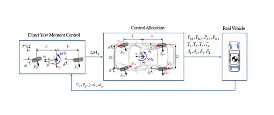
This paper investigates the control allocation with 4WIB, 4WID and 4WIS provided in IWM-driven EVs for vehicle stability control. The control performance measures considered in this paper are maneuverability and lateral stability. For control allocation with those actuators, vehicle stability controllers have been proposed in previous works [21,23,27]. The controller has been configured with the upper-level controller and the lower-level controller in this research. The upper one determines required yaw moment for vehicle stability based on several controller design methodologies. The required yaw moment, calculated by the upper one, is realized by tire forces generated by several actuators such as 4WIB, 4WID and 4WIS. The methodology needed to determine tire forces generated by 4WIB, 4WID and 4WIS is proposed. To investigate and compare the control performance in terms of several actuator combinations with 4WIB, 4WID, and 4WIS, simulation has been conducted on a driving simulation tool, CarSim. Figure 2 shows the schematic diagram that describes the outline of this research.
This paper consists of four sections. In Section 2, the configuration of the proposed vehicle stability controller, i.e., upper-level and lower-level controllers, is explained. The control allocation method, which is needed to decide the steering angles, traction torque and brake pressure of 4WIS, 4WIB and 4WID, is proposed in Section 2. Simulation is conducted and simulation results are analyzed in Section 3. In the last section, Section 4, the conclusion of this research is given.
2. Design of Vehicle Stability Controller
2.1. Design of Upper-Level Controller
To design an upper-level controller, various types of vehicle model can be considered. Three-degree-of-freedom (DOF) planar models and 2-DOF bicycle models are the most typical models of driving control [9,21,23,27]. In this paper, a 2-DOF bicycle model is used to design the proposed yaw moment control algorithm because it is much simpler than a 3-DOF planar model.
Figure 3 represents the 2-DOF model. In this model, ‘2 DOF’ stands for yaw and lateral motions. It is assumed that the longitudinal velocity vx is constant. Therefore, state variables in this formula are yaw rate, γ, and side-slip angle, β. The lateral velocity vy is included in the definition of β. With these variables, the differential equation of motion for this model is given in Equation (2). In Equation (2), the control yaw moment ΔMB is the control input to be calculated to enhance vehicle stability. Tire slip angles of the front wheel αf and of the rear wheel αr are defined as Equation (3) using γ, β, and vx. In Equation (2), the lateral tire forces of the front and rear wheels, Fyf and Fyr, are assumed as functions of the tire slip angles, αf and αr, respectively. These relations are given in Equation (4) [27]. Non-linearity between Fyf and αf will be explained in Section 2.3. The desired yaw rate, γd, is derived using the steering angle of front wheels, δf and the longitudinal velocity vx [23].
The aim of the proposed controller is to enhance both maneuverability and lateral stability. The definition of maneuverability in this research is that yaw motion of a vehicle accurately follows the driver’s intention. The driver’s intention can be represented as γd. Thus, in order to enhance maneuverability, the controller should make the yaw rate of a vehicle γ follow γd. Lateral stability means that β is maintained as small as possible. In the previous research, β must be smaller than 3deg for lateral stability [23]. Even on a low-friction surface, maneuvering performance can be in the acceptable region by virtue of a vehicle stability controller. However, β can diverge on the slippery surface although γ is close to γd [6]. Thus, maintaining β as small as possible is very important in terms of lateral stability. To consider this fact, the phase plane of β and its derivative have been adopted for lateral stability control in the previous research [28].
In short, a controller, which is designed to enhance maneuvering performance and lateral stability, should make γ follow γd and β be smaller value than 3deg. For these reasons, sliding surface consists of two error terms as shown in Equation (5). γ − γd stands for yaw-rate error. The tuning parameter η is to compromise γ − γd with β. The stability condition given in Equation (6) should be satisfied to minimize both error terms [23,27]. From Equations (2), (5) and (6), ΔMB is obtained as Equation (7).
In Equation (7), Fyf, Fyr, and β are not easy to measure. Wheel force transducers can be used to measure the tire forces but they are expensive. Thus, Fyf, Fyr, and β must be estimated by observers or estimators. In this research, a sliding mode observer, as given in [29], is adopted to estimate Fyf and Fyr because it has a simple structure and shows good performance in estimating the lateral tire forces. β is estimated by signal-based extended Kalman filter (EKF), as proposed in the previous research, because it is quite simple and does not require any models [30].
2.2. Design of Lower-Level Controller: Control Allocation
Subsequent to computation of ΔMB from the upper-level controller, tire forces are to be determined by the lower-level controller. Tire forces are generated by actuator combinations with 4WIB, 4WID and 4WIS. In this research, the WPCA method is used for distribution of the tire forces generated by actuator combinations.
Figure 4 shows ΔMB and the distributed tire forces on four wheels. In Figure 4, the driver’s intention is heading for positive yaw direction, i.e., counter clockwise. In Figure 4, Fx1, Fx2, Fx3 and Fx4 are the longitudinal driving/braking forces. These forces are generated by 4WIB or 4WID. The signs of Fx1 and Fx3 are negative in Figure 4. Fy1, Fy2, Fy3, and Fy4 are the lateral tire forces, generated by 4WIS. Directions of all tire forces should be decided according to the direction of ΔMB. A WPCA is adopted to determine the tire forces [9,10,21,22,23].
In Figure 4, the steering angles, δ1, δ2, δ3, and δ4, of each wheel can be set for each actuator in 4WIS. This is the most general case. For instance, if AFS is adopted, the front steering angles will be δ1 = δ2, while the rear steering angles are δ3 = δ4 = 0. For another example, in the case of 4WS, the steering angles are set to δ1 = δ2 and δ3 = δ4. With the principle, the steering angle combination is given in Equation (1). The steering angles, δ1, δ2, δ3, and δ4, correspond to Fy1, Fy2, Fy3 and Fy4, respectively. Of these, for stability control, steering systems and driving/braking systems can be combined in several ways. For instance, AFS or 4WS can be combined with 4WIB or 4WID or 4WIB + 4WID [21,22,23,27].
Equation (8) shows the geometric relation of the tire forces and ΔMB. Equation (9) shows the definition of the objective function for WPCA.
In Equation (9), the variable ξi is defined as ξi ≡ μFzi i.e., the radius of friction circle at each wheel. In Equation (9), Fzi stands for the vertical force of each wheel, and μ is the tire-road friction coefficient. In Equation (9), ξi cannot be measured. Therefore, it should be estimated. Fzi can be estimated from the longitudinal and lateral acceleration signals. In the previous work [20], this approach has been used for unified chassis control. μ can be also estimated from dual EKFs [31]. In Equation (9), ρ is a diagonal matrix which consists of fictitious variable weights ρi. Originally, ρ is used for several purposes. In this research, ρ is used to cope with several actuator combinations such as 4WIB and 4WIB + 4WIS, 4WIB + 4WID, and 4WIB + 4WID + 4WIS. The explanation on the roles of ρ can be found in the previous work [21,23].
Equations (8) and (9) are the general form of control allocation with 4WIB, 4WID and 4WIS for vehicle stability control. With these equations, actuator combinations with 4WIB and 4WID can be represented with the variable weights, ρ5, ρ6. ρ7, and ρ8. A detailed description of how to represent the actuator combinations with 4WIB and 4WID can be found in previous research [21,23].
Equations (8) and (9) can represent several steering actuators such as AFS, FWIS, RWIS, 4WS and 4WIS. For example, if AFS is adopted as a steering actuator, then Equation (8) should be modified to meet the constraints that Fy1 is to be equal to Fy2, as given in Equation (1). For this purpose, Equation (8) is modified into Equation (10). To meet the constraint that Fy3 and Fy4 are to be zero, as given in Equation (1), the set of variable weights in Equation (9) should be set as Equation (11).
In Equation (11), ε is set to a very small value, i.e., 10−4, and the variable weights corresponding to Fy3 and Fy4 are set to very large values, i.e., 1. Therefore, Fy3 and Fy4 become always zero from optimization. In Equation (11), ∙ represents arbitrary variable weights used to represent actuator combinations with 4WIB and 4WID. If FWIS is adopted as a steering actuator, Equation (8) is used, and the set of variable weights should be set to Equation (11). If ARS is adopted as a steering actuator, then Equation (8) should be modified to Equation (12), and the set of variable weights should be set to Equation (13). If RWIS is adopted as a steering actuator, Equation (8) is used, and the set of variable weights should be set to Equation (13). If 4WS is adopted as a steering actuator, then Equation (8) should be modified to Equation (14), and the set of variable weights should be set to Equation (15).
The optimization problem, as given in Equations (8) and (9), is a quadratic programming problem. Also, it has an equality constraint that needs to be considered. Adopting the method of Lagrange multiplier with the problem, the solution of the optimization problem can be easily solved as Equation (16). After obtaining the solution of the optimization, xopt, the longitudinal tire forces Fx1~4 are converted into braking pressure PB, and traction one TD as Equation (17).
In Equation (17), rw is the radius of a tire and KB is the torque-to-pressure constant of a brake system. From the optimal solution, the lateral tire forces are converted into the corrective steering angles Δδi of wheels. The method how to determine the corrective steering angles, i.e., Δδi, will be given in the next subsection.
As explained above, arbitrary actuator combinations with 4WIB, 4WID and 4WIS can be represented in the single framework of WPCA. This can be done with the equality constraint, Equation (8), and its modified one and the set of variable weights corresponding to a particular actuator combination. For these reasons, WPCA proposed in this paper is the most general framework used to determine Fx1, Fx2, Fx3, Fx4, Fy1, Fy2, Fy3 and Fy4, generated by several actuator combinations, to produce ΔMB.
2.3. Determination of Steering Angles of Four-Wheel Independent Steering (4WIS) from Tire Forces
After obtaining the solution of the optimization problem using WPCA, Fy1~4 should be generated and converted into appropriate steering angles of steering actuators. In particular, AFS and FWIS use front steering actuators, while 4WS and 4WIS use both front and rear ones. Braking pressures of 4WIB and traction torques of 4WID are easy to determine from Fx1~4 with a brief formulation, as shown in Equation (17). Compared to PB and TD, the corrective steering angles of the steering actuators, i.e., Δδi, is not easy to determine from the lateral tire forces of WPCA. To determine Δδi of each steering actuator, tire slip angle αi should be calculated, firstly. After calculating αi, Δδi can be obtained by using Equation (3). Four methods can be used for this purpose.
The first one is to use a linear tire model on Fyf and Fyr, as shown in Equation (18). From Equation (18), Δδi can be obtained as Equation (19) [23]. In Equation (19), Ci stands for the cornering stiffness of each wheel. σ is a tuning parameter modulating the magnitude of Ci. In general, reducing σ can enhance cornering performance because it generates larger Δδi. The parameter σ is the most important one influencing the control performance [9]. In Equation (19), Fyi and αi are regarded as a linear relation and the non-linearity between them is neglected. Let this procedure denote Method#1. Method#1 can be applied to AFS, FWIS, 4WS and 4WIS.
The second one is to use the definition of the slip angle, Equation (3) [32]. Equation (3) can be converted into Equation (20). From Equation (20), Δδi of each wheel is obtained as Equation (21). As shown in Equation (21), it is necessary to obtain αi for the purpose of calculating Δδi. In this method, αi is calculated as Equation (22) from the linearized Fyi of front and rear wheels, as shown in Equation (18). Equation (3) is valid only to the 2-DOF bicycle model. Therefore, it can be applied to AFS and 4WS. For FWIS and 4WIS, this method uses the definition of slip angle, as given in Equation (23). Following the identical procedure for AFS and 4WS, Δδi is calculated as (24).
In Equations (22) and (24), Ci is supposed to be constant. This procedure has validity upon the linear region with a certain value of αi. Let this procedure denote Method#2. The others are the procedures using the estimated cornering stiffness instead of Ci in Equations (19), (22) and (24). For the purpose, the cornering stiffness Ci in those equations are to be estimated. In order to estimate Ci, β or vy are to be estimated using the method shown in [30]. Subsequently, the estimated αi, i.e., , is obtained from Equations (3) and (23) with the estimated β or vy, as given in Equations (20) and (23), respectively. In this step, Δδi must be set to zero for accuracy of estimation. With , the lateral tire force Fyic is calculated via the hyperbolic tangent formula, as shown in Equation (25) [9]. Fyic is different from Fyi, the optimal solution of WPCA. Finally, is obtained from dividing Fyic by . In Equation (25), Fzi and μ are estimated with the methods given in the previous works [21,31], and Coi is an appropriately selected cornering stiffness. Let two procedures denote Method#3 and Method#4 as given in Equations (19), (22) and (24), respectively.
3. Validation with Simulation
In this section, a simulation study was undertaken to verify the performance of the vehicle stability controller with the actuator combinations of 4WIS, 4WIB and 4WID.
The simulation was conducted via CarSim [33]. The controller was implemented on MATLAB/Simulink environment. There were several test procedures, i.e., open-loop and closed-loop maneuvers, for vehicle stability control. A typical open-loop maneuver for test is sine-with-dwell, used for testing ESC or a vehicle stability controller in National Highway Traffic Safety Administration (NHTSA) Federal Motor Vehicle Safety Standard (FMVSS) No. 126 [34]. There are two tests in the regulation. The first is directional stability test and the second is responsiveness one. Instead of using these tests, a closed-loop maneuver with a driver model is adopted in this paper. A typical closed-loop maneuver is double lane change on a moose test track. As described in the previous works, the double lane change on a moose test track at high speed is so severe that any other maneuvers can be covered by it [21]. Therefore, the simulation scenario adopted in this paper is the double lane change maneuver on a moose test course with a closed-loop driver model [21]. The steering wheel angle was applied by the driver model, which is built in the CarSim Software. This is the implementation of the previous research [35]. The driver model replicates an unskilled driver, whose preview time was modelled as 0.75 s [23]. The initial vehicle speed was set to 80 km/h. Tire-road friction coefficient was regarded as a constant value, 0.6. This scenario is the most drastic one, compared to sine-with-dwell and step steer [23,27]. Therefore, this scenario is appropriate to investigate vehicle stability.
For this simulation, the D-segment sport utility vehicle (SUV) model was chosen, which is also a built-in model in CarSim Software. For the controller design with the 2-DOF bicycle model, the parameters given in Figure 2 were needed. These parameters refer to the D-segment SUV model and are shown in Table 1. The controller gain K and the tuning parameter η are set to 20 and 1, respectively. The actuators, 4WIB, 4WID and 4WIS, were modelled as the 1st-order system. Time constants of these systems were set to 0.05, 0.05 and 0.05, respectively. In 4WID, the maximum power of the IWM for each wheel is 37 kW (UQM HiTor). The speed-torque map including the gear ratio, 10:1, is shown in Figure 5. The torque characteristic of the IWM is cited from previous research [36].
In this research, the maneuverability is investigated via the reference of FMVSS 126. This criterion requires the yaw rate error is less than 0.08 rad/s. The lateral stability is investigated by the condition that β is less than 3 degrees [34]. Without any controllers, the target vehicle cannot maintain its stability because μ is low while the vehicle speed is high. In other words, the driver’s steering wheel angle, the yaw rate error and the side-slip angle of the uncontrolled vehicle diverged if there are no control actions.
The first simulation was undertaken to investigate the effects of the methods of steering angle determination on the control performance, as given in the Section 2.3. 4WIS was selected as the steering actuator. The four methods, i.e., Method#1, Method#2, Method#3 and Method#4, were applied for 4WIS. Figure 6 and Figure 7 show the simulation results and the steering angles of 4WIS with the four methods. In Figure 7, the legends FL, FR, RL and RR represents the front left, front right, rear left and rear right wheels, respectively. Contrary to the uncontrolled vehicle, the controlled vehicles maintained their stability, as shown in Figure 6.
As shown in Figure 6a,b, Method#1 and Method#3 show nearly identical performance. By contrast, Method#2 and Method#4 show worse performance than Method#1 and Method#3 in terms of the lateral stability. Method#1 and Method#3 applied nearly identical steering angles, as shown in Figure 7. Among the methods, Method#1 shows the best performance in terms of the maneuverability and the lateral stability, as pointed out in previous work [9]. So, Method#1 is adopted as the method of steering angle determination for the steering actuators, i.e., AFS, FWIS, 4WS and 4WIS, hereafter.
The second simulation was conducted with five actuator combinations, i.e., 4WIB, 4WIS, 4WIS + 4WID, 4WIS + 4WIB and 4WIS + 4WIB + 4WID. 4WIB was solely applied without any other actuators for comparison. Figure 8 and Figure 9 show the simulation results and the control inputs for each actuator combination. Figure 8a,b show that the controlled vehicles with five actuator combinations satisfy FMVSS 126 criteria. Moreover, the yaw rate errors, the side-slip angles and the steering wheel angles are nearly identical to one another for each actuator combination. This means that 4WIS has a dominant role in maintaining stability. In other words, 4WIS itself is capable of enhancing the maneuverability and the lateral stability regardless of the use of other actuators such as 4WIB and 4WID.
As shown in Figure 8c, the vehicle speeds vary according to a particular actuator combination. For example, if 4WIB is used, the speed will be decreased further. By contrast, if 4WID is used, the speed will be decreased less. Generally, the reduction of vehicle speed makes the yaw rate error and the side-slip angle smaller. However, this does not hold for the results given in Figure 8a. This means that the control yaw moment cannot be fully generated with the sole use of 4WIB. On the other hand, the sole use of 4WIS is capable of doing this. If multiple actuators are combined, then it is superior to a single actuator in terms of performance and control effort. However, this does not hold for 4WIS. This still holds for several actuator combinations in terms of control effort, as shown in Figure 9. In other words, the control input of a particular actuator can be reduced by using another.
The third simulation was conducted in order to compare the actuator combinations with steering actuators, i.e., AFS, FWIS, 4WS and 4WID, and 4WIB/4WID. For this purpose, four measures were considered: the maximum absolute yaw rate error (MAYRE), the maximum absolute side-slip angle (MASSA), the minimum longitudinal velocity (MinVx), and the maximum absolute lateral offset error (MALOE). The MASSA and MAYRE have been used to represent the lateral stability and the maneuverability, respectively. These values were calculated after performing the simulation during 10 s. Table 2, Table 3, Table 4 and Table 5 show MAYRE, MASSA, MinVx and MALOE for each actuator combination with respect to steering actuators. In these tables, Single means that only one of the steering actuators, i.e., AFS, FWIS, 4WS and 4WIS, was used.
In view of MAYRE and MASSA, 4WS or 4WS with 4WID is the best actuator combination, as given in Table 2 and Table 3. In view of MinVx and MALOE, the results show the same tendency. Single front wheel actuators such as AFS and FWIS show large side-slip angles due to the small reduction of vehicle speed, as shown in Table 3. As pointed out in previous work [23,27,37], rear wheel steering such as 4WS and 4WIS can drastically reduce the side-slip angle. This can be found in Table 3. From the overall perspective, 4WS itself is the best single actuator, and 4WS with 4WID is the best actuator combination.
As shown in these tables, 4WS and 4WIS are superior to AFS and FWIS in terms of all performance measures under the condition that 4WIB is not used. This is caused by rear wheel steering. In particular, 4WIS shows good performance regardless of the use of 4WIB and 4WID. In other words, 4WIS itself is capable of enhancing the maneuverability and the lateral stability without or with other actuators such as 4WIB and 4WID. By contrast, 4WS shows worse performances with 4WIB. Therefore, it is recommended that 4WS should not be used with 4WIB.
4. Conclusions
In this research, the vehicle stability controller was designed with four combinations of actuator, i.e., 4WIB, 4WID, and 4WIS on in-wheel motor driven electric vehicles. In the upper-level controller, the control yaw moment was calculated with sliding mode control. In the lower-level controller, the control yaw moment was distributed into tire forces, generated by a particular actuator combination of 4WIB, 4WID and 4WIS. Variable weights were adopted to represent several actuator combinations in a single framework. Four methods were introduced in order to determine the steering angles of steering actuators. Simulation was conducted on CarSim. From the simulation results, the effects of actuator combinations and the methods of steering angle determination on control performance were analyzed. A notable feature of the controller is that 4WS with 4WID shows the best performance, and that 4WIS is capable of generating the required control yaw moment by itself. Unexpectedly, any actuator combinations with 4WIB show slightly poor performance. Therefore, it is recommended that 4WIS and 4WS can be solely used, and that 4WID is a good actuator to be combined with 4WS.
Author Contributions
S.Y. conceptualized the main idea, designed this study, and participated in formulating the idea, as well as validating the proposed method and results. J.N. implemented the methodology and drafted the manuscript. All authors have read and agreed to the published version of the manuscript.
Funding
This paper was supported by Research Program of Wonkwang University 2020.
Conflicts of Interest
The authors declare no conflict of interest.
References
- Murata, S. Innovation by in-wheel-motor drive unit. Veh. Syst. Dyn. 2012, 50, 807–830. [Google Scholar] [CrossRef]
- Kim, D.; Shin, K.; Kim, Y.; Cheon, J. Integrated design of in-wheel motor system on rear wheels for small electric vehicle. In Proceedings of the EVS25 World Battery, Hybrid and Fuel Cell Electric Vehicle Symposium, Shenzhen, China, 7–9 November 2010. [Google Scholar]
- Eberle, U. GM’s Research Strategy: Towards a Hydrogen-Based Transportation System; FuncHy Workshop: Hamburg, Germany, 2016. [Google Scholar]
- Koo, T.; Hong, S.; Kim, D.; Tae, H.; Kim, J.; Won, J.; Bhae, H.Y. A Study on the Controllability of the Vehicle Steer-by-Wire Systems; SAE Technical Paper 2020-01-0646; SAE International: Warrendale, PA, USA, 2020. [Google Scholar] [CrossRef]
- Cheon, J.S. Brake by Wire System Configuration and Functions Using Front EWB (Electric Wedge Brake) and Rear EMB (Electro-Mechanical Brake) Actuators; SAE Technical Paper 2010-01-1708; SAE International: Warrendale, PA, USA, 2010. [Google Scholar] [CrossRef]
- van Zanten, A.T.; Erhardt, R.; Pfaff, G.; Kost, F.; Hartmann, U.; Ehret, T. Control aspects of the Bosch-VDC. In Proceedings of the 3th International Symposium on Advanced Vehicle Control, Aachen, Germany, 25–27 June 1996; pp. 573–608. [Google Scholar]
- Zhai, L.; Sun, T.; Wang, J. Electronic stability control based on motor driving and braking torque distribution for a four in-wheel motor drive electric vehicle. IEEE Trans. Veh. Technol. 2016, 65, 4726–4739. [Google Scholar] [CrossRef]
- Croft-White, M.; Harrison, M. Study of torque vectoring for all-wheel drive vehicles. Veh. Syst. Dyn. 2006, 44, 313–320. [Google Scholar] [CrossRef]
- Yim, S. Comparison among active front, front independent, 4-wheel and 4-wheel independent steering systems for vehicle stability control. Electronics 2020, 9, 798. [Google Scholar] [CrossRef]
- Wang, J.; Longoria, R.G. Coordinated vehicle dynamics control with control distribution. In Proceedings of the 2006 American Control Conference, Minneapolis, MN, USA, 14–16 June 2006; pp. 5348–5353. [Google Scholar]
- Wang, J.; Solis, J.M.; Longoria, R.G. On the control allocation for coordinated ground vehicle dynamics control systems. In Proceedings of the 2007 American Control Conference, New York, NY, USA, 11–13 July 2007; pp. 5724–5729. [Google Scholar]
- Schofield, B. Vehicle Dynamics Control for Rollover Prevention. Ph.D. Thesis, Lund University, Lund, Sweden, 2006. [Google Scholar]
- Tjønnas, J.; Johansen, T.A. Stabilization of automotive vehicles using active steering and adaptive brake control allocation. IEEE Trans. Control Syst. Technol. 2010, 18, 545–558. [Google Scholar] [CrossRef] [Green Version]
- Tøndel, P.; Johansen, T.A. Control allocation for yaw stabilization in automotive vehicles using multiparametric nonlinear programming. In Proceedings of the 2005 American Control Conference, Portland, OR, USA, 8–10 June 2005; pp. 453–458. [Google Scholar]
- Fredriksson, J.; Andreasson, J.; Laine, L. Wheel force distribution for improved handling in a hybrid electric vehicle using nonlinear control. In Proceedings of the 43rd IEEE Conference on Decision and Control, Nassau, Bahamas, 14–17 December 2004; pp. 4081–4086. [Google Scholar]
- Jin, X.; Yu, Z.; Yin, G.; Wang, J. Improving vehicle handling stability based on combined AFS and DYC system via robust Takagi-Sugeno fuzzy control. IEEE Trans. Intell. Transp. Syst. 2018, 19, 2696–2707. [Google Scholar] [CrossRef]
- Mokhiamar, O.; Abe, M. Simultaneous optimal distribution of lateral and longitudinal tire forces for the model following control. ASME J. Dyn. Syst. Meas. Control. 2004, 126, 753–763. [Google Scholar] [CrossRef]
- Mokhiamar, O.; Abe, M. How the four wheels should share forces in an optimum cooperative chassis control. Control. Eng. Pract. 2006, 14, 295–304. [Google Scholar] [CrossRef]
- Ono, E.; Hattori, Y.; Muragishi, Y.; Koibuchi, K. Vehicle dynamics integrated control for four-wheel-distributed steering and four-wheel-distributed traction/braking systems. Veh. Syst. Dyn. 2006, 44, 139–151. [Google Scholar] [CrossRef]
- Cho, W.; Yoon, J.; Kim, J.; Hur, J.; Yi, K. An investigation into unified chassis control scheme for optimized vehicle stability and maneuverability. Veh. Syst. Dyn. 2008, 46, 87–105. [Google Scholar] [CrossRef]
- Yim, S.; Choi, J.; Yi, K. Coordinated control of hybrid 4WD vehicles for enhanced maneuverability and lateral stability. IEEE Trans. Veh. Technol. 2012, 61, 1946–1950. [Google Scholar] [CrossRef]
- Fujimoto, H.; Maeda, K. Optimal yaw-rate control for electric vehicles with active front-rear steering and four-wheel driving-braking force distribution. In Proceedings of the IECON 2013—39th Annual Conference of the IEEE Industrial Electronics Society, Vienna, Austria, 10–13 November 2013; pp. 6514–6519. [Google Scholar]
- Yim, S. Coordinated control with electronic stability control and active steering devices. J. Mech. Sci. Technol. 2015, 29, 5409–5416. [Google Scholar] [CrossRef]
- Jin, L.; Gao, L.; Jiang, Y.; Chen, M.; Zheng, Y.; Li, K. Research on the control and coordination of four-wheel independent driving/steering electric vehicle. Adv. Mech. Eng. 2017, 9, 1–13. [Google Scholar] [CrossRef]
- Hang, P.; Chen, X.; Luo, F. Path-Tracking Controller Design for a 4WIS and 4WID Electric Vehicle with Steer-by-Wire System; SAE Technical Paper 2017-01-1954; SAE International: Warrendale, PA, USA, 2017. [Google Scholar] [CrossRef]
- Hang, P.; Chen, X. Integrated chassis control algorithm design for path tracking based on four-wheel steering and direct yaw-moment control. Proc. Inst. Mech. Eng. Part I J. Syst. Control Eng. 2019, 233, 625–641. [Google Scholar] [CrossRef]
- Nah, J.; Yim, S. Optimization of control allocation with ESC, AFS, ARS and TVD in integrated chassis control. J. Mech. Sci. Technol. 2019, 33, 2941–2948. [Google Scholar] [CrossRef]
- Chung, T.; Yi, K. Design and evaluation of side slip angle-based vehicle stability control scheme on a virtual test track. IEEE Trans. Control Syst. Technol. 2006, 14, 224–234. [Google Scholar] [CrossRef]
- Baffet, G.; Charara, A.; Lechner, D. Estimation of vehicle side-slip, tire force and wheel cornering stiffness. Control Eng. Pract. 2009, 17, 1255–1264. [Google Scholar] [CrossRef] [Green Version]
- Kim, H.H.; Ryu, J. Sideslip angle estimation considering short-duration longitudinal velocity variation. Int. J. Automot. Technol. 2011, 12, 545–553. [Google Scholar] [CrossRef]
- Hu, D.; Zong, C.; Na, X. Combined estimation of vehicle states and road friction coefficients using dual extended Kalman filter. In Proceedings of the 10th International Symposium on Advanced Vehicle Control, Loughborough, UK, 22–25 August 2010; pp. 309–314. [Google Scholar]
- Rajamani, R. Vehicle Dynamics and Control; Springer: New York, NY, USA, 2006. [Google Scholar]
- Mechanical Simulation Corporation. VS Browser: Reference Manual, The graphical user interfaces of BikeSim, CarSim, and TruckSim; Mechanical Simulation Corporation: Ann Arbor, MI, USA, 2009. [Google Scholar]
- National Highway Traffic Safety Administration. FMVSS No. 126, Electronic Stability Control. Systems: NHTSA Final Regulatory Impact Analysis; National Highway Traffic Safety Administration: Washington, DC, USA, 2007.
- MacAdam, C.C. Application of an optimal preview control for simulation of closed-loop automobile driving. IEEE Trans. Syst. Man Cybern. 1981, 11, 393–399. [Google Scholar] [CrossRef]
- Pinto, L.; Aldworth, S.; Watkinson, M.; Jeary, P.; Franco-Jorge, M. Advanced yaw motion control of a hybrid vehicle using twin rear electric motors. In Proceedings of the 10th International Symposium on Advanced Vehicle Control, Loughborough, UK, 22–25 August 2010; pp. 640–645. [Google Scholar]
- Yim, S. Performance improvement of integrated chassis control with determination of rear wheel steering angle. Trans. KSME Part. A 2017, 41, 111–119. [Google Scholar]
Figure 1.
Four steering angles of four-wheel independent steering (4WIS).

Figure 2.
Schematic diagram of the research.

Figure 3.
2-DOF bicycle model.

Figure 4.
Coordinate system corresponding to tire forces and control yaw moment.

Figure 5.
Capacity curve of a motor in in-wheel motor (IWM) system.

Figure 6.
Simulation results of 4WIS for each method.

Figure 7.
Steering angles of 4WIS for each method.

Figure 8.
Simulation results for each actuator combination.

Figure 9.
Control inputs of each actuator for each actuator combination.


Table 1.
Parameter of D-segment SUV in CarSim.
| ms | 1429 kg | lf | 1.05 m |
| Iz | 1765 kg⋅m2 | lr | 1.57 m |
| Cf | 36,000 N/rad | tf | 0.750 m |
| Cr | 50,000 N/rad | tr | 0.745 m |
Table 2.
Maximum absolute yaw rate errors for each actuator combination (degrees/s).
| Single | 4WIB | 4WID | 4WIB + 4WID | |
|---|---|---|---|---|
| AFS | 3.9 | 2.4 | 1.8 | 2.3 |
| FWIS | 3.0 | 2.6 | 2.3 | 2.4 |
| 4WS | 1.2 | 2.0 | 1.1 | 2.0 |
| 4WIS | 1.7 | 1.7 | 1.6 | 1.6 |
Table 3.
Maximum absolute side-slip angles for each actuator combination (deg.).
| Single | 4WIB | 4WID | 4WIB + 4WID | |
|---|---|---|---|---|
| AFS | 3.4 | 1.8 | 2.0 | 1.7 |
| FWIS | 3.6 | 2.0 | 2.9 | 1.9 |
| 4WS | 1.2 | 1.5 | 1.1 | 1.5 |
| 4WIS | 1.4 | 1.4 | 1.4 | 1.4 |
Table 4.
Minimum longitudinal velocities for each actuator combination (km/h).
| Single | 4WIB | 4WID | 4WIB + 4WID | |
|---|---|---|---|---|
| AFS | 65.7 | 56.4 | 71.7 | 59.4 |
| FWIS | 64.9 | 59.6 | 68.9 | 61.9 |
| 4WS | 65.9 | 57.1 | 68.0 | 58.8 |
| 4WIS | 65.5 | 62.9 | 66.7 | 63.8 |
Table 5.
Maximum absolute lateral offset errors for each actuator combination (m).
| Single | 4WIB | 4WID | 4WIB + 4WID | |
|---|---|---|---|---|
| AFS | 3.62 | 3.47 | 3.86 | 3.53 |
| FWIS | 3.73 | 3.60 | 3.77 | 3.66 |
| 4WS | 2.87 | 3.02 | 2.95 | 3.03 |
| 4WIS | 2.97 | 3.00 | 2.98 | 3.03 |
Publisher’s Note: MDPI stays neutral with regard to jurisdictional claims in published maps and institutional affiliations. |
© 2020 by the authors. Licensee MDPI, Basel, Switzerland. This article is an open access article distributed under the terms and conditions of the Creative Commons Attribution (CC BY) license (http://creativecommons.org/licenses/by/4.0/).
Share and Cite
MDPI and ACS Style
Nah, J.; Yim, S. Vehicle Stability Control with Four-Wheel Independent Braking, Drive and Steering on In-Wheel Motor-Driven Electric Vehicles. Electronics 2020, 9, 1934. https://doi.org/10.3390/electronics9111934
AMA Style
Nah J, Yim S. Vehicle Stability Control with Four-Wheel Independent Braking, Drive and Steering on In-Wheel Motor-Driven Electric Vehicles. Electronics. 2020; 9(11):1934. https://doi.org/10.3390/electronics9111934
Chicago/Turabian StyleNah, Jaewon, and Seongjin Yim. 2020. "Vehicle Stability Control with Four-Wheel Independent Braking, Drive and Steering on In-Wheel Motor-Driven Electric Vehicles" Electronics 9, no. 11: 1934. https://doi.org/10.3390/electronics9111934
Note that from the first issue of 2016, this journal uses article numbers instead of page numbers. See further details here.