Analytical Performance Evaluation of Massive MIMO Techniques for SC-FDE Modulations


1
Instituto Universitário de Lisboa (ISCTE – IUL), Av. das Forças Armadas, 1649-026 Lisboa, Portugal
2
IT—Instituto de Telecomunicações, Av. Rovisco Pais, 1, Torre Norte, Piso 10, 1049-001 Lisboa, Portugal
3
FCT—Universidade Nova de Lisboa, Monte da Caparica, 2829-516 Caparica, Portugal
*
Author to whom correspondence should be addressed.
Electronics 2020, 9(3), 533; https://doi.org/10.3390/electronics9030533
Submission received: 29 February 2020
/
Revised: 19 March 2020
/
Accepted: 20 March 2020
/
Published: 24 March 2020
(This article belongs to the Special Issue Cooperative Communications for Future Wireless Systems)
Abstract
:In the Fifth Generation of telecommunications networks (5G), it is possible to use massive Multiple Input Multiple Output (MIMO) systems, which require efficient receivers capable of reaching good performance values. MIMO systems can also be extended to massive MIMO (mMIMO) systems, while maintaining their, sometimes exceptional, performance. However, we must be aware that this implies an increase in the receiver complexity. Therefore, the use of mMIMO in 5G and future generations of mobile receivers will only be feasible if they use very efficient algorithms, so as to maintain their excellent performance, while coping with increasing and critical user demands. Having this in mind, this paper presents and compares three types of receivers used in MIMO systems, for further use with mMIMO systems, which use Single-Carrier with Frequency-Domain Equalization (SC-FDE), Iterative Block Decision Feedback Equalization (IB-DFE) and Maximum Ratio Combining (MRC) techniques. This paper presents and compares the theoretical and simulated performance values for these receivers in terms of their Bit Error Rate (BER) and correlation factor. While one of the receivers studied in this paper achieves a BER performance nearly matching the Matched Filter Bound (MFB), the other receivers (IB-DFE and MRC) are more than 1 dB away from MFB. The results obtained in this paper can help the development of ongoing research involving hybrid analog/digital receivers for 5G and future generations of mobile communications.
1. Introduction
With the constant increase in users’ needs, in particular, the interconnection of all their communication devices, and its access to the Internet everywhere, the Fourth Generation (4G) of telecommunications has to be rethought. The Fifth Generation (5G) of telecommunications networks arises as a response to existing technology limitations. The 5G network is predicted to have an increase of 10 times in spectral efficiency and 1000 times of system capacity when compared to 4G. It is also expected that this technology is energy efficient [1].
According to the report published by [2], at the end of 2019, about 13 million subscribers to the 5G technology were already expected. In October 2019, right before the official launch of this technology, more than 10 million users have already been registered. Despite the 5G launch ramp, 4G will still be dominant and will reach its peak in 2022, and then it will become superseded by 5G technology. It is also expected that by 2025, 4G will cover around of the world’s population, and 5G will cover only of the population but at half of the data traffic. Also, according to the same report, the providers of this technology are working on a second generation that intends to reduce power consumption, increase frequencies and implement more integrated designs.
The migration to 5G implies new developments in the system design, changes in components and system architecture. One way to achieve these changes is to use massive Multiple Input Multiple Output (mMIMO) [3]. This architecture consists of the existence of multiple antennas in the receiver and transmitter. This implementation allows these systems to have a substantial increase in the data rate and an improvement, not only in energy efficiency, but also in reliability of the connections [1,4].
Channel estimation is one of the limiting factors in this type of system. Another problem is related to the assignment of sequences of finite orthogonal pilots. When the sequences of pilots is reused, it increases the contamination of pilots and coherent interference [3].
With the mMIMO system, the Single-Carrier with Frequency-Domain Equalization (SC-FDE) can be used since this technique allows a lower envelope fluctuation, when compared with Orthogonal Frequency Division Multiplexing (OFDM) [5,6,7]. SC-FDE allows an efficient power amplification at the Mobile Terminal (MT). In the uplink transmission, the linear Frequency-Domain Equalization (FDE) can be replaced with an iterative FDE on the receiver, such as the Iterative Block Decision Feedback Equalization (IB-DFE) [8]. This replacement leads to an increase in the receiver performance [9].
In the mMIMO system, the number of antennas in the receiver and transmitter increases to tens or hundreds of antennas. This implies the use of large matrices, which is a serious problem in receivers based on the IB-DFE concept [10,11], since this type of receiver requires matrix inversions for each subcarrier and each iteration implies intensive computational processing. Some iterative receivers that achieve similar performance do not require matrix inversions. These receivers can implement, e.g., Maximum Ratio Combining (MRC), which requires the calculation of the hermitian of the channel matrix, or the Equal Gain Combining (EGC) that only needs phase rotations [12,13]. The main problems associated with these low complexity receivers are related to the high interference between different transmitted streams and the Inter-Symbol Interference (ISI).
There are several studies regarding the different receivers that can be used with mMIMO systems [14,15,16,17], where the performance achieved is compared with the Matched Filter Bound (MFB). Authors from in [18] propose a hybrid receiver that combines IB-DFE with MRC, achieving performance values similar to MFB in its second iteration.
In this paper, the performance achieved by IB-DFE, MRC, the hybrid receiver and the correlation factor is presented and compared with the theoretical values for the same receiver. The work presented in this paper can be extended to hybrid analog/digital equalization scenarios for massive MIMO systems as presented in [19,20].
In Section 2 the comparison of receivers that can be used in mMimo systems is presented. In Section 3 the proposed system is described and in Section 4 the IB-DFE, MRC and hybrid receivers are presented, followed by Section 5 where the Bit Error Rate (BER) performance and the correlation factors are calculated for the same receivers. In Section 6, the results are presented and discussed. Lastly, in Section 7, the conclusions achieved are drawn.
The following denotation is employed in this paper: In general, the lower case letters denote time-domain variables, while upper case letters denote frequency-domain variables. Bold upper letters represent matrices or vector; is the identity matrix ; the complex conjugate, transpose and Hermitian of is denoted by and respectively. The expectation of x is represented by and , , , denotes respectively sample, “hard decision” and “soft decision” estimation of x.
2. Receivers
In the literature [14,15,16,17] we can find the description of very efficient and appropriate receivers for use in MIMO systems, able to be extended for mMIMO. This section summarizes their main properties.
- ZF: Zero Forcing (ZF) [21] is a simple receiver technique that applies the inverse of the channel frequency response to the received signal to equalize the communications channel. It allows for a perfect separation of the different users as well as the removal of the ISI, however, it cannot be used in most practical applications as when the received signal is very weak, that is when the Signal-to-Noise ratio (SNR) is very low, it compensates by amplifying the received signal and completely deteriorates the overall SNR when trying to invert values close to zero. In terms of complexity it is not very efficient as well, since it requires the inversion of matrices;
- IB-DFE: The IB-DFE receiver is an iterative receiver where each stream is detected one at a time and the interference is canceled with the help of the streams already detected. When the number of iteration increases, the interference cancellation is improved, improving the overall performance. As with the ZF, this receiver also has the disadvantage of using matrix inversions;
- MRC: The MRC receiver combines the different received branch signals in order to maximize the received SNR ratio. The main advantage is that there are no matrices inversions;
- EGC: The EGC receiver only involves phase rotations, combining all received signals with unitary weights to achieve a high SNR. Like MRC, the EGC does not need matrices inversions.
Table 1 presents a summary of the BER performance achieved by the previous receivers, as well as the number of required iterations to achieve it, where applicable, based on the work presented in [15].
As we can observe, the referred ZF and IB-DFE receivers have the same BER performance as the MFB, for very similar values of , remarkably for the IB-DFE. In this table, only the non-iterative versions of MRC and EGC receivers were considered.
3. System Characterization
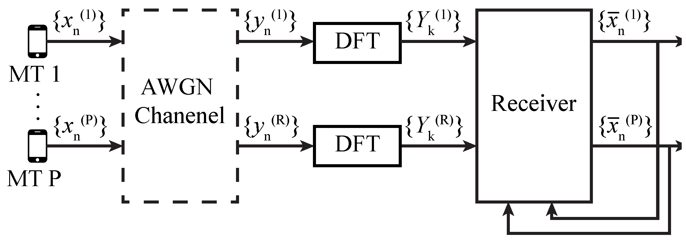
This paper explores a scenario that implements massive MIMO communications in a highly frequency selective channel and a Single Carrier modulation in the uplink transmission. In this scenario, the communication is established between a MT equipped with P single transmitting antennas and a Base Station (BS) equipped with R receiving antennas, with and a perfect synchronization.
In order to remove the ISI, a cyclic prefix, which is larger than the maximum system delay, is added to each transmitted block and removed in the reception side. The MT transmits a block of N data symbols which is received in the BS antenna as corresponding to a frequency-domain block . The block can also be represented in the matrix format , being given by Equation (1):
where the channel matrix for the subcarrier is represented by , the frequency-domain block of the transmitted block is represented by and represents the channel noise. In Figure 1 the considered scenario is depicted.
4. Receivers Design
Since massive MIMO systems are expected to operate with a great number of antennas in the transmitter and the receiver, it is important that the receivers used in these systems have as few matrix inversions as possible. The necessary resources used in matrix inversion increase significantly with the number of entries in that matrix. The greater the number of R and T, the higher the associated complexity.
Throughout this section, different iterative receivers based on FDE are presented. In this type of receiver, the estimated signal at the iteration for the subcarrier is given by:
with denoting the feedforward coefficients and denoting the feedback coefficients, responsible to reduce the residual ISI after the first iteration. represents the estimated signal for the previous iteration which is the Discrete Fourier Transform (DFT) of . is selected according to a mapping rule, in this case, a Quadrature Phase-Shift Keying (QPSK) with Gray mapping, (i.e., ). The average values for , according to [22], are given by:
where
and
For the first iteration, and since there are no previous iterations, Equation (2) can be simplified to:
Each FDE receiver has different equations for the and coefficients. Section 4.1, Section 4.2 and Section 4.3 present the equations for three distinct receivers.
4.1. IB-DFE
The IB-DFE receiver has already been extensively tested and validated, as mentioned in Section 1. In order to minimize error probability, authors from [11,14,16] define expressions for and coefficients, which are given by:
and
where is a normalization parameter ensuring that the overall frequency-response of the “channel plus receiver” for each MT has an average value of 1, i.e.,
The is given by:
where is a diagonal matrix containing the correlation factor between transmitted and detected symbols. and represents the variance of the real and imaginary parts of the channel noise and data samples, respectively.
4.2. MRC
As shown in Section 4.1, the IB-DFE receiver requires the inversion of the channel matrix in the estimation of the received signal. This situation requires too much complexity when moving to an mMIMO system, where there are multiple receiving and transmitting antennas.
As explained in [14,15,17], the MRC receiver combines the different received branch signals in order to maximize the received SNR ratio. In fact, the phases of the received signals are fixed and the conjugate of the channel matrix is used to weight them. The small correlation between the different transmitting and receiving antennas allows us to make the following approach:
When considering moderate values, the residual interference cannot be neglected. In order to improve the performance of this receiver, an iterative version should be implemented, such as the IB-DFE receiver. Equation (2) is also considered by this receiver by only changing the feedforward and feedback coefficient equations. Therefore, feedback coefficients are given by Equation (9) and the feedforward coefficients are given by:
where is a diagonal matrix and the element is given by .
4.3. IB-DFE Receiver Combined with MRC
A receiver for mMIMO scenarios was provided in [18] and it reduces the complexity of matrix inversion since it only occurs on the first iteration, achieving performance values very close to MFB at the end of the second iteration. This receiver, in the first iteration, behaves as an IB-DFE receiver and, in the remaining iterations, as the MRC receiver.
In the remaining iterations, the feedforward and feedback coefficients are given by Equations (9) and (13), respectively.
In Figure 2, the structure of this receiver is depicted.
5. Theoretical BER Performance
Each of the receivers presented so far aims to minimize the Mean Squared Error (MSE) which, in turn, decreases BER performance. This minimization takes place through precise selection of feedforward and feedback coefficients. For a QPSK constellation with Gray mapping rule, as considered in this paper, the BER can be calculated by:
where represents the Gaussian error function and is given by:
The MSE, represented by , can be calculated using:
As presented in [23] and [11], where allowing the redefinition of to . In matrix format, is given by:
where is a mean zero error vector for MT and , with defined by:
which, in turn, defines the correlation factor that supplies a blockwise reliability measure of the estimates employed in the feedback loop and associated to the iteration [22,24]. For a QPSK constellations, and can be approximately given by:
with
and
Once the data and noise components have zero mean and are uncorrelated, Equation (17) which represents the MSE can be extended, resulting in Equation (23):
For simplicity, in Equation (23), the user and subcarrier dependency has been dropped, with the exception for the factor. We assume:
and
Equation (23), after some manipulation, can be written as:
6. Performance Results
In this section, performance results for the three mentioned receivers are presented. For these results, there are different scenarios where the number of transmitting and receiving antennas are changed. Initially, a MIMO scenario with 3 iterations, 4 transmitting antennas and 8 receiving antennas is presented. Then, this scenario is extended to a massive MIMO scenario and the number of antennas was increased 8 times, while keeping the same ratio and number of iterations.
For simulation purposes, it is considered that in each MT, P, a SC-FDE modulation is applied transmitting 100 blocks with 256 data symbols (), selected from a QPSK constellation under Gray mapping. Perfect synchronization and channel estimation are also assumed.
Performance values are presented as BER values, which in turn is in function of , where is the average bit energy associated with the receiving antennas and represents the unilateral power spectral density of the Additive White Gaussian Noise (AWGN) channel noise. The lowest bound for the BER performance that a receiver can reach is fixed in the MFB performance which is also presented.
6.1. MIMO Scenario
In this scenario, a set of 3 iterations with and antennas is considered.
In Figure 3, the theoretical/simulated BER performance for both receivers (IB-DFE and MRC) is depicted in Figure 3a, as well as the correlation factor, shown in Figure 3b.
According to Figure 3a, it is possible to verify that the IB-DFE receiver has a BER performance closer to the MFB. In its third iteration, for a BER of , this receiver presents a difference of less than 1 dB to the MFB. For the same BER, MRC receivers present a worse performance. When comparing the simulated and theoretical values of BER performance, it should be pointed out that the theoretical curves achieve better performance, with the exception of the first IB-DFE iteration where the two curves are identical. In Figure 3b, both receivers, for the first iteration, present values for the correlation factor that never reach the optimum value 1, which implies a worse BER performance, as depicted in Figure 3a. From the second iteration onward, the correlation factor values are close to 1, allowing the achievement of BER performance values close to the MFB.
The performance results of a receiver that combines IB-DFE in the first iteration with MRC in the remaining iterations are depicted in Figure 4. According to Figure 4a, the BER performance of the receiver, in its first iteration is about 3 dB away from MFB and in the remaining iterations, the result approaches the MFB. The theoretical and simulated BER performance values are also very similar. The poor values of BER performance are accompanied by the correlation factor values. As represented in Figure 4b in its first iteration, these values are quite far from the optimal value 1. In the remaining iterations, the value of the correlation factor converges faster to 1.
In fact, in the third iteration, this receiver has a difference of dB when compared with the MFB, for a BER of while for a BER of this difference is reduced to approximately dB.
6.2. Massive MIMO Scenario
By increasing the number of transmitting and receiving antennas and , the system can be considered as a massimo MIMO system.
Figure 5 shows the performance results for IB-DFE and MRC receivers. As for the MIMO system, the first iteration of the MRC presents weak values as shown in Figure 5a. For a BER of , the simulated value for IB-DFE is dB higher than MFB. In the case of MRC, when compared to MFB, the theoretical value is increased by dB and the simulated value also increases by dB. In Figure 5b the correlation factor is very similar to the one presented in Figure 3b. This is due to the fact that the ratio is the same.
When analyzing the results for the receiver that combines the IB-DFE with the MRC (Figure 6), the results obtained via simulation practically match with the theoretical values for the BER performance, as shown in Figure 6a. At the end of the second iteration, for a BER of , the receiver is approximately dB away from MFB and in its third iteration, the difference for the MFB is only dB. The correlation factor, depicted in Figure 6b in the second iteration of the receiver, for an of 5 dB, is practically 1.
7. Conclusions
This paper presents the study of FDE-type receivers that can be used in massive MIMO systems. The structures of three receivers, where the complexity depends on the estimation of the received signal, are discussed.
The BER performance of these receivers is simulated and compared with theoretical values. The impact of the correlation factor on BER performance is also studied.
One of the receivers propose in this paper is a receiver that combines, in its first iteration, the IB-DFE receiver and in the remaining iterations the MRC receiver. The BER performance achieved by this receiver, in massive MIMO scenarios, is only dB away from the MFB, in its third iteration, and the simulated/theoretical values match very closely.
Author Contributions
Conceptualization, D.F., F.C. and R.D.; investigation, D.F., F.C. and R.D.; software, D.F.; supervision, F.C. and R.D.; validation, F.C. and R.D.; visualization, D.F.; writing—original draft, D.F., F.C. and R.D.; writing—review and editing, F.C. and R.D. All authors have read and agreed to the published version of the manuscript.
Funding
This work was supported by projects CoSHARE (LISBOA-01-0145-FEDER-0307095-PTDC/EEI-TEL/30709/2017), MASSIVE5G (SAICT-45-2017-02) and Instituto de Telecomunicações (UIDB/EEA/50008/2020), and funded by Fundo Europeu de Desenvolvimento Regional (FEDER), through Programa Operacional Regional LISBOA (LISBOA2020), and by national funds, through Fundação para a Ciência e Tecnologia (FCT).
Conflicts of Interest
The authors declare no conflict of interest.
References
- Wang, C.X.; Haider, F.; Gao, X.; You, X.H.; Yang, Y.; Yuan, D.; Aggoune, H.M.; Haas, H.; Fletcher, S.; Hepsaydir, E. Cellular architecture and key technologies for 5G wireless communication networks. IEEE Commun. Mag. 2014, 52, 122–130. [Google Scholar] [CrossRef] [Green Version]
- Ericsson. Ericsson Mobility Report—November 2019; Technical Report; Ericsson: Stockholm, Sweden, 2019. [Google Scholar]
- Boccardi, F.; Heath, R.; Lozano, A.; Marzetta, T.; Popovski, P. Five disruptive technology directions for 5G. IEEE Commun. Mag. 2014, 52, 74–80. [Google Scholar] [CrossRef] [Green Version]
- Larsson, E.G.; Edfors, O.; Tufvesson, F.; Marzetta, T.L. Massive MIMO for next generation wireless systems. IEEE Commun. Mag. 2014, 52, 186–195. [Google Scholar] [CrossRef] [Green Version]
- Chang, R.W. Synthesis of Band-Limited Orthogonal Signals for Multichannel Data Transmission. Bell Syst. Tech. J. 1966, 45, 1775–1796. [Google Scholar] [CrossRef]
- Sari, H.; Karam, G.; Jeanclaude, I. An analysis of orthogonal frequency-division multiplexing for mobile radio applications. In Proceedings of the IEEE Vehicular Technology Conference (VTC), Stockholm, Sweden, 8 June 1994; pp. 1635–1639. [Google Scholar] [CrossRef]
- Falconer, D.; Ariyavisitakul, S.; Benyamin-Seeyar, A.; Eidson, B. Frequency domain equalization for single-carrier broadband wireless systems. IEEE Commun. Mag. 2002, 40, 58–66. [Google Scholar] [CrossRef] [Green Version]
- Benvenuto, N.; Tomasin, S. Block iterative DFE for single carrier modulation. Electron. Lett. 2002, 38, 1144–1145. [Google Scholar] [CrossRef] [Green Version]
- Benvenuto, N.; Dinis, R.; Falconer, D.; Tomasin, S. Single Carrier Modulation With Nonlinear Frequency Domain Equalization: An Idea Whose Time Has Come—Again. Proc. IEEE 2010, 98, 69–96. [Google Scholar] [CrossRef] [Green Version]
- Dinis, R.; Kalbasi, R.; Falconer, D.; Banihashemi, A. Iterative Layered Space-Time Receivers for Single-Carrier Transmission Over Severe Time-Dispersive Channels. IEEE Commun. Lett. 2004, 8, 579–581. [Google Scholar] [CrossRef]
- Ribeiro, F.; Dinis, R.; Cercas, F.; Silva, A. Receiver design for the uplink of base station cooperation systems employing SC-FDE modulations. EURASIP J. Wirel. Commun. Netw. 2015, 2015, 7. [Google Scholar] [CrossRef] [Green Version]
- Dinis, R.; Carvalho, P.; Borges, D. Low Complexity MRC and EGC Based Receivers for SC-FDE Modulations With Massive Mimo Schemes. IEEE Glob. Conf. Signal Inf. Process. Glob. SIP 2016, 1, 1–4. [Google Scholar]
- Montezuma, P.; Dinis, R. Iterative receiver based on the EGC for massive MIMO schemes using SC-FDE modulations. Electron. Lett. 2016, 52, 972–974. [Google Scholar] [CrossRef]
- Bento, P.; Pereira, A.; Dinis, R.; Gomes, M.; Silva, V. Frequency-Domain Detection without Matrix Inversions for mmWave Communications with Correlated Massive MIMO Channels. IEEE Veh. Technol. Conf. 2017, 2017. [Google Scholar] [CrossRef]
- Cabral, L.; Fernandes, D.; Cercas, F.; Dinis, R. Efficient frequency-domain detection for massive MIMO systems. In Proceedings of the 2017 South Eastern European Design Automation, Computer Engineering, Computer Networks and Social Media Conference (SEEDA-CECNSM), Kastoria, Greece, 23 September 2017; pp. 1–5. [Google Scholar] [CrossRef] [Green Version]
- Ribeiro, F.C.; Guerreiro, J.; Dinis, R.; Cercas, F.; Silva, A. Reduced complexity detection in MIMO systems with SC-FDE modulations and iterative DFE receivers. J. Sens. Actuator Netw. 2018, 7, 17. [Google Scholar] [CrossRef] [Green Version]
- Pereira, A.; Bento, P.; Gomes, M.; Dinis, R.; Silva, V. Iterative MRC and EGC Receivers for MIMO-OFDM Systems. IEEE Veh. Technol. Conf. 2018, 2018, 1–4. [Google Scholar] [CrossRef]
- Fernandes, D.; Cercas, F.; Dinis, R. Iterative Receiver Combining IB-DFE with MRC for Massive MIMO Schemes. Procedia Comput. Sci. 2017, 109, 305–310. [Google Scholar] [CrossRef]
- Magueta, R.; Enes, R.; Teodoro, S.; Silva, A.; Castanheira, D.; Dinis, R.; Gameiro, A. Hybrid Nonlinear Multiuser Equalizer for mmWave Massive MIMO CE-OFDM Systems. IEEE Int. Symp. Pers. Indoor Mob. Radio Commun. PIMRC 2019, 2019. [Google Scholar] [CrossRef]
- Magueta, R.; Castanheira, D.; Pedrosa, P.; Dinis, R. Wideband Millimeter Wave Massive MIMO Systems. Sensors 2020, 20, 575. [Google Scholar] [CrossRef] [PubMed] [Green Version]
- Goldsmith, A. Wireless Communications; Cambridge University Press: Cambridge, UK, 2005. [Google Scholar] [CrossRef] [Green Version]
- Gusmão, A.; Torres, P.; Dinis, R.; Esteves, N. A turbo FDE technique for reduced-CP SC-based block transmission systems. IEEE Trans. Commun. 2007, 55, 16–20. [Google Scholar] [CrossRef]
- Casal Ribeiro, F.; Dinis, R.; Cercas, F.; Silva, A. On the performance of SC-FDE receivers for Base Station cooperation systems with rate-limited backhaul links. Proceedings of 2013 9th International ITG Conference on Systems, Communication and Coding, SCC 2013, Munich, Germany, 1 June 2013; p. 9. [Google Scholar]
- Silva, F.; Dinis, R.; Montezuma, P. Estimation of the Feedback Reliability for IB-DFE Receivers. ISRN Commun. Netw. 2011, 2011, 1–7. [Google Scholar] [CrossRef] [Green Version]
Figure 1.
System scenario.

Figure 2.
Iterative Block Decision Feedback Equalization (IB-DFE) receiver combined with the Maximum Ratio Combining (MRC) structure.
Figure 2.
Iterative Block Decision Feedback Equalization (IB-DFE) receiver combined with the Maximum Ratio Combining (MRC) structure.

Figure 3.
Theoretical/simulated BER performance and correlation factor for IB-DFE and MRC receivers in a Multiple Input Multiple Output (MIMO) system with 3 iterations. (a) BER performance. (b) Correlation factor (ρ).
Figure 3.
Theoretical/simulated BER performance and correlation factor for IB-DFE and MRC receivers in a Multiple Input Multiple Output (MIMO) system with 3 iterations. (a) BER performance. (b) Correlation factor (ρ).

Figure 4.
Theoretical/simulated BER performance and correlation factor for a receiver that combines IB-DFE and MRC in a MIMO system with 3 iterations. (a) BER performance. (b) Correlation factor (ρ).
Figure 4.
Theoretical/simulated BER performance and correlation factor for a receiver that combines IB-DFE and MRC in a MIMO system with 3 iterations. (a) BER performance. (b) Correlation factor (ρ).

Figure 5.
Theoretical/simulated BER performance and correlation factor for IB-DFE and MRC receivers in an mMIMO system with 3 iterations. (a) BER performance. (b) Correlation factor (ρ).
Figure 5.
Theoretical/simulated BER performance and correlation factor for IB-DFE and MRC receivers in an mMIMO system with 3 iterations. (a) BER performance. (b) Correlation factor (ρ).

Figure 6.
Theoretical/simulated BER performance and correlation factor for a receiver that combines IB-DFE andMRC in an mMIMO system with 3 iterations. (a) BER performance. (b) Correlation factor (ρ).
Figure 6.
Theoretical/simulated BER performance and correlation factor for a receiver that combines IB-DFE andMRC in an mMIMO system with 3 iterations. (a) BER performance. (b) Correlation factor (ρ).


Table 1.
[dB] for the Bit Error Rate (BER) performance of the scenarios presented in [15].
Table 1.
[dB] for the Bit Error Rate (BER) performance of the scenarios presented in [15].
| BER | Iteration | MFB | ZF | IB-DFE | MRC | EGC |
|---|---|---|---|---|---|---|
| 1 | ||||||
| 4 | − | − | − |
© 2020 by the authors. Licensee MDPI, Basel, Switzerland. This article is an open access article distributed under the terms and conditions of the Creative Commons Attribution (CC BY) license (http://creativecommons.org/licenses/by/4.0/).
Share and Cite
MDPI and ACS Style
Fernandes, D.; Cercas, F.; Dinis, R. Analytical Performance Evaluation of Massive MIMO Techniques for SC-FDE Modulations. Electronics 2020, 9, 533. https://doi.org/10.3390/electronics9030533
AMA Style
Fernandes D, Cercas F, Dinis R. Analytical Performance Evaluation of Massive MIMO Techniques for SC-FDE Modulations. Electronics. 2020; 9(3):533. https://doi.org/10.3390/electronics9030533
Chicago/Turabian StyleFernandes, Daniel, Francisco Cercas, and Rui Dinis. 2020. "Analytical Performance Evaluation of Massive MIMO Techniques for SC-FDE Modulations" Electronics 9, no. 3: 533. https://doi.org/10.3390/electronics9030533
Note that from the first issue of 2016, this journal uses article numbers instead of page numbers. See further details here.