Energy-Aware Sensing on Battery-Less LoRaWAN Devices with Energy Harvesting
by
 , and
, and
Adnan Sabovic
1,*, 
Carmen Delgado
1 ,
,
Dragan Subotic
1,
Bart Jooris
2,
Eli De Poorter
2 and
Jeroen Famaey
1 1
IDLab, University of Antwerp—imec, 2000 Antwerp, Belgium
2
IDLab, Ghent University—imec, 9000 Ghent, Belgium
*
Author to whom correspondence should be addressed.
Electronics 2020, 9(6), 904; https://doi.org/10.3390/electronics9060904
Submission received: 8 May 2020
/
Revised: 22 May 2020
/
Accepted: 25 May 2020
/
Published: 29 May 2020
(This article belongs to the Special Issue Wireless Network Protocols and Performance Evaluation)
Abstract
:Billions of Internet of Things (IoT) devices rely on batteries as the main power source. These batteries are short-lived, bulky and harmful to the environment. Battery-less devices provide a promising alternative for a sustainable IoT, where energy harvested from the environment is stored in small capacitors. This constrained energy storage and the unpredictable energy harvested result in intermittent on–off behavior of the device. Measuring and understanding the current consumption and execution time of different tasks of IoT applications is crucial to properly operate these battery-less devices. In this paper, we study how to properly schedule sensing and transmission tasks on a battery-less LoRaWAN device. We analyze the trade-off between sleeping and allowing the device to turn off between the execution of application tasks. This study allows us to properly define the device configuration (i.e., capacitor size) based on the application tasks (i.e., sensing and sending) and environmental conditions (i.e., harvesting rate). We define an optimization problem that determines the optimal capacitor voltage at which the device should start performing its tasks. Our results show that a device using LoRaWAN Class A can measure the temperature and transmit its data at least once every 5 s if it can harvest at least 10 mA of current and uses a relatively small capacitor of 10 mF or less. At harvesting rates below 3 mA, it is necessary to turn off the device between application cycles and use a larger supercapacitor of at least 140 mF. In this case, the device can transmit a temperature measurement once every 60–100 s.
1. Introduction
The Internet of Things (IoT) vision enables billions of tiny sensors to communicate and cooperate with each other while performing different tasks such as sensing (i.e., temperature, pressure, and humidity), processing and sending the data. Currently, most IoT devices rely on batteries as the main power source which, even when rechargeable, are short-lived, lasting at most a few years. As the number of devices grows, replacing and disposing of billions of dead and hazardous batteries becomes costly and ecologically unacceptable [1]. In addition, these batteries are bulky, dangerous when not carefully protected, and temperature sensitive [2]. As such, they are incompatible with a sustainable IoT vision.
To achieve this sustainable IoT vision, battery-less IoT devices that depend on harvested environmental energy are a promising solution. Using this approach, battery-less devices harvest available energy from different environmental sources (e.g., solar, kinetic, and RF energy) and store it in small capacitors [3,4]. Compared to batteries, these tiny capacitors are smaller and last more than a decade, thanks to their ability to handle a large number of charge cycles [2]. Battery-less devices are almost maintenance free which also makes them more suitable to deploy in hard-to-reach places.
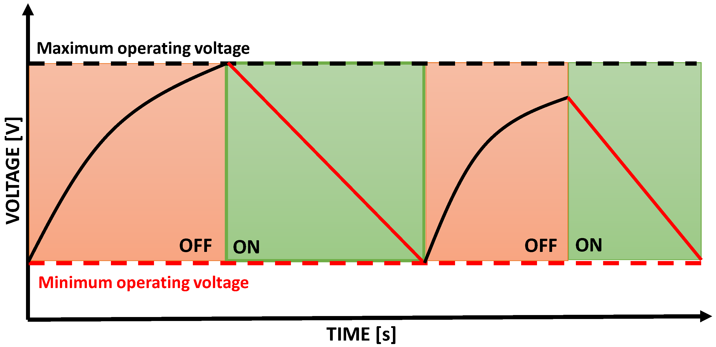
However, this new vision also has some disadvantages and challenges to handle. First, the amount of transferred energy from the source to the energy harvester is not deterministic but stochastic [5]. The dynamism and unpredictable environment conditions can cause power failures at any time lasting a couple of seconds, minutes, or even hours. Each type of harvesting source has a different behavior and generates different volumes of energy (e.g., solar energy is unavailable at night and harvesting from RF energy sources is hard over long distances) [1]. Considering these facts, it is very difficult to predict the behavior of battery-less IoT devices and schedule the application tasks in a reliable way. Second, the amount of consumed energy also depends on the device behavior during runtime. Every change in the behavior of the sensor node such as going from sleep or idle mode to transmit the data or sensing the temperature causes changes in the voltage which affects the stored energy in the capacitor. Third, the energy storage of battery-less devices is scarce, especially when the capacitor is very small. In the end, all these things lead to intermittent execution, as shown in Figure 1, where the device turns on and off frequently as it depletes and replenishes the stored energy in the capacitor.
Advancements in reducing the energy consumption, device size, and improvements in energy supplying circuits, but also in the way of communication between these devices, lead the future development of a strong and sustainable IoT [6]. Low-Power Wide-Area Networks (LPWANs) are a new set of long-range radio technologies with low energy consumption that use the unlicensed sub-1GHz ISM (industrial, scientific, and medical) radio bands [7]. In this work, we consider IoT devices using the LoRaWAN [8] communication protocol, which has been developed by the LoRa Alliance, and is one of the most popular LPWAN technologies.
To effectively use battery-less IoT devices, the applications running on them should be able to properly handle their intermittency. To this end, we present an approach to intelligently schedule application tasks on a battery-less IoT sensor using LoRaWAN, based on the device’s available and harvested energy. The main contributions in this paper are: (i) a mathematical model of the energy life cycle of a battery-less LoRaWAN Class A IoT device and its sensing application tasks; (ii) accurate device profiling methodology of different application tasks and device states; (iii) an optimization problem to define the optimal capacitor voltage at which the device should start performing its tasks; and (iv) realistic evaluation of our approach based on real measurements combined with simulation results, and a validation using a hardware prototype.
The remainder of this paper is structured as follows. Section 2 reviews the state of the art on the energy consumption of LoRaWAN, energy harvesting, task scheduling, and battery-less IoT devices. In Section 3, we describe the theoretical model for intermittent battery-less LoRaWAN devices together with the proposed optimization problem. Section 4 describes our device profiling methodology to accurately determine the execution time and energy consumption of different application tasks and device states. Section 5 shows the evaluation results and discussion. All the necessary documentation related to our experiments and results can be found in Supplementary Materials. Finally, conclusions are provided in Section 6.
2. Related Work
The vision of sustainable and efficient computing in the IoT [6] faces a huge number of challenges such as the high level of energy consumption and limited energy availability. Using low power technologies and modeling the energy consumption, the lifetime of IoT devices can be optimized, but there is still a problem when the available energy is spent. Battery-less devices that use the energy harvested from their environment present great potential to enable a sustainable IoT vision and increase the energy efficiency and lifetime of future solutions.
Energy consumption models can help to understand the device behavior. Bouguera et al. [7] presented an energy consumption model for LoRaWAN sensor nodes. They studied the trade-off among the LoRaWAN communication range, spreading factor, and transmission power and showed that the consumed energy depends on different parameters (e.g., payload size and spreading factor). However, they focused on battery-powered devices, while we consider a capacitor as the main energy storage unit which collects energy from environmental sources. Sherazi et al. [9] presented a model for battery-powered LoRaWAN devices to evaluate and prolong their lifetime depending on different energy harvesting sources. In this mathematical model, they concluded that the energy consumption of a LoRaWAN device depends on the different times between the transmission and monitoring tasks. Probabilistic energy models for hybrid energy harvesting IoT nodes were shown by Dogay et al. [5]. Energy is obtained from multiple sources (i.e., RF, thermal, and photovoltaic) and stored in the energy storage unit such as rechargeable batteries. This approach enables predictability of the parameters of energy harvesting systems (i.e., harvested energy, stored energy, and recharging efficiency). They tested MICAz (http://www.cmt-gmbh.de/Produkte/WirelessSensorNetworks/MPR2400.html), an IEEE 802.15.4 compliant board, and considered the needed energy for sending the data. In contrast of these works, we consider that the device stores the energy in a capacitor which can charge and discharge more quickly, and this behavior leads to more frequent power failures during the task execution.
There are also some models for battery-less IoT devices. Loubet et al. [10] presented and characterized the implementation of a LoRaWAN battery-less wireless sensing node for a capacitor of 22 mF. In their calculations, the voltage thresholds are defined and one cycle with measurements, processing, and sending the data without reception windows can be repeated every 2.13 s. Eliminating some states of the LoRaWAN device means reducing the power consumption, which cannot be used for all kinds of IoT applications, such as applications that require receiving an acknowledgment or answer from the gateway. Compared to them, we consider the complete LoRaWAN Class A cycle with both reception windows and also evaluate a wider range of capacitor sizes (between 0.47 mF and 140 mF).
Delgado et al. [2] modeled the intermittent behavior of a battery-less LoRaWAN Class A device. Their model is able to determine under which conditions a LoRaWAN Class A device can work without batteries. In this paper, we extend the work of Delgado et al. in several ways. Our model is based on a current rather than voltage source (which better captures certain energy harvesters such as photovoltaics). Moreover, we evaluate the model based on real measurements, and use it to find the optimal capacitor voltage at which to start the different device application tasks.
Battery-less devices harvest energy from their environment and store it in a small capacitor. This energy is unpredictable and inconsistent. Besides, these capacitors are usually very small and not able to store large amounts of the energy which leads to intermittent behavior of these devices. Different models and proper ways of scheduling the application tasks are proposed. Dividing the program into atomic sub-tasks can adapt the execution to the available energy, and avoid power failures. AsTAR [3] presented an energy-aware task scheduler that supports heterogeneity and addresses environmental dynamism. In their work, they considered larger super capacitors (between 1 and 5 Farad), which may be too large to fit into tiny battery-less IoT devices. Instead, we focus on smaller capacitors such as 0.47 mF that are more suitable for battery-less IoT devices. Karimi et al. [11] presented an energy scheduling scheme that keeps track of time and ensures periodic task execution while efficiently utilizing intermittent power sources. They used the power-based energy source and included the sensing tasks (i.e., temperature/humidity measurement), considering larger capacitors that enable the device to run for a longer time. Kiwan et al. [12] presented Alpaca, a low-overhead programming model for intermittent computing on energy-harvesting devices. Alpaca splits the program into multiple tasks and if a task cannot be finished due to lack of the available energy, it will be executed again. The main problem here is the risk of task starvation, because Alpaca does not advance any other task if the previous one cannot be completed. In addition, their design cannot schedule events in the future or perform periodic sensing tasks. Compared to them, our study allows us to properly define the device configuration (i.e., capacitor size) based on current consumption and different environmental conditions (i.e., harvesting rate), avoiding the possibility of power failures during the task execution.
Another task-based model for programming the intermittent behavior of energy harvesting devices was presented by Colin et al. [13]. In their approach, named Chain, the computation is presented as a sequence of tasks and forward progress is guaranteed as long as the energy demand never exceeds the total energy storage capacity of the device. Majid et al. [14] presented an adaptive and efficient task-based execution model, named Coala, which can adapt its execution to the incoming energy conditions at runtime. Coala makes faster progress through the computation by coalescing statically-defined tasks when more energy is available and otherwise the progress is latched at sub-task granularity.
The main difference with the state of the art is that we focus on scheduling tasks in an energy-aware fashion, taking into account energy harvesting and consumption, which is not the case with other schedulers. Instead of the datasheet, we consider real measured values and evaluate the energy cost of every specific state of the device. We analyze the specific requirements (e.g., capacitor size, energy harvesting rate, and required capacitor voltage) needed for IoT sensing applications that include two tasks (using a sensor and transmitting the sensed data). We consider a capacitor as the main energy storage unit and evaluate a wide range of capacitor sizes. Defining the scheduling policies for periodic tasks, we can calculate the optimal starting voltage at which the device shows the best performance avoiding the possibility of power failures.
3. Theoretical Model for a Battery-Less LoRaWAN Device
3.1. Capacitor Charging Model
The theoretical model for a battery-less LoRaWAN device that we present in this paper builds on previous work by Delgado et al. [2], but, instead of using a voltage source, we use a current source. Using a current source is more realistic for popular energy harvesters, such as photovoltaic cells. Battery-less IoT devices are equipped with a capacitor, microcontroller MCU, radio unit, harvester mechanism, and the needed sensors [2]. Figure 2 shows the simplified electrical circuit which considers three main parts: the harvester (energy source), the capacitor (energy storage), and the consumer of the energy (i.e., MCU, radio, and sensors).
The amount of transferred energy from the environmental energy source to the energy harvester is different for every specific type such as radiation, vibration, or thermal. In reality, the selected harvester depends on the type of energy source, and, in our work, we consider a constant current source. During different time intervals, the device is in different states that consume different amounts of energy, leading to either charging or discharging of the capacitor. The capacitor size, current consumption of different states of the LoRaWAN device, and the selected harvesting rate directly affect the charge and discharge rate of the capacitor.
All active components such as the sensors, radio, or MCU consume energy from the capacitor. Each device state, which combines specific states of the individual device components, has a specific current consumption and is modeled as a load resistance (in ). The load resistance is modeled as a function (in ) and can be calculated as follows:
where is the current consumption for a specific combination of states of the device components (e.g., sensor off, MCU active, and radio transmitting) and is the reference voltage at which is obtained.
The function returns as output the minimum value between the voltage of the capacitor () after t seconds, starting from voltage , while the device consumes a current , and the maximum allowed operating voltage E.
where is the current produced by the energy harvester in Ampere, and C is the capacitance in Farads. This formula can be used to determine if the device is able to successfully complete a specific task, by checking if stays above the minimum operating voltage . If the capacitor voltage goes below , the device is not able to stay on, and will shut down until it harvests enough energy to turn on again. The function calculates the starting capacitor voltage (), given an ending voltage , transpired time t, and a total device current consumption :
For an application task A, with a total execution time and current consumption , this function can be used to calculate the minimum capacitor voltage needed to successfully execute the task without the device turning off, as . Finally, the time needed to get a voltage level starting from an initial voltage and a total current consumption is modeled as a function and can be derived from Equation (2) by solving it for time instead of voltage as follows:
3.2. Task Scheduling Approaches
The main problem of battery-less devices is their intermittent behavior and based on that how to schedule the tasks in order to avoid power failures. In our work, the device needs to perform two application tasks: (i) using a sensor to measure some environmental variable (e.g., the temperature); and (ii) sending the measured data to a cloud server. The goal of the device is to transmit up-to-date sensor measurements as frequently as possible. Moreover, it should minimize the delay between measuring and transmitting, to ensure the freshness of the transmitted sensor data. The process of collecting a measurement, transmitting it, and recharging the capacitor up to original voltage is referred to as an application cycle. Two different approaches are defined and analyzed for our experiments which are explained in more detail in the next subsections.
3.2.1. Sleep Approach
Using this approach, the device will remain in sleep mode if the amount of available energy in the capacitor is not enough to perform the next task, as shown in Figure 3. The device will start at the configurable initial voltage . The first task is measuring the temperature and it will start whenever the device reaches the required voltage , which can be calculated as , where and are the execution time and current consumption of the sensing task. They are constant and can be measured as shown in Section 4. In case the value of is lower than , the device goes into sleep mode and waits until the required voltage is reached. The amount of time the device spends in sleep mode, between and , can be calculated as .
In the other case, where is lower than , is set to and the sensing task is executed immediately. Given the time and energy required for collecting a sensor measurement, the capacitor voltage at the end of sensing can be calculated as .
Subsequently, the transmission task will start once the capacitor voltage is high enough to finish the transmission without going below the minimum allowed voltage (i.e., ). This voltage can be calculated as where and are the total time and average current consumption during the full transmission state (cf. Section 4). In reality, the transmission state consists of several substates that are described in Section 3.3 and we omit this calculation for simplicity. In case that the value of is higher than , the device needs to sleep again until the needed voltage is achieved. The required sleep time can be calculated as . Otherwise, if is below , is set equal to . Finally, if the calculated value of is lower than , the device has to sleep again in order to reach and start the next cycle. This sleep time is equal to .
Given this process, the total cycle time for a given cycle starting voltage can be calculated as the sum + + + + . Here, and are constants, while , , and depend on the input variable , as well as on the device and environmental parameters E, and C.
3.2.2. TurnOff Approach
The main issue with the Sleep approach is the fact that enough energy needs to be harvested to increase the capacitor voltage while the device is in sleep mode, which, depending on the sleep mode power consumption, can be problematic if the energy harvesting rate is low. To alleviate this, we also consider an approach where the device turns all components off between task executions. A power management circuit can be used to turn on the device again once a specific capacitor voltage is reached. Using the TurnOff approach, the device will remain in the off mode to collect some more energy if the amount of available energy in the capacitor is not enough to perform the full cycle of tasks, as shown in Figure 4. In this approach, the device will always perform sensing and transmission immediately one after the other, as initial experiments showed that turning off between both tasks never performed better than executing them immediately. The device will start at the configurable initial voltage . The full cycle of tasks will start whenever the device reaches the required voltage .
To calculate , needs to be calculated first as where and are the total time and average current consumption during the full transmission state (cf. Section 4). Based on the obtained result, can be calculated as , where and are the execution time and current consumption of the sensing task. Finally, the required start-up voltage, , can be calculated as , where and are the execution time and current consumption of the start-up task (cf. Section 4). In case the value of is lower than , the device goes into off mode, in order to reach the required voltage , for , and then again at the end of task cycle for to reach again and close the application cycle.
On the other hand, if is lower than , is set to and the full cycle of tasks executes immediately. Finally, if the calculated value of (which now will be higher than ) is lower than , the device will only turn off for (as will be 0) in order to reach and start the next cycle.
Given this process, the total cycle time for a given cycle starting voltage , can be calculated as the sum + + + . Here, and are constants, while and depend on the input variable , as well as on the device and environmental parameters E, and C.
3.3. LoRaWAN Class A Device Transmission Task
As mentioned above, we consider the use of LoRaWAN for transmission of the data. In this section, we introduce the different steps that comprise a LoRaWAN transmission, in order to be able to determine the related energy consumption and execution time . The LoRaWAN standard defines three main classes of end devices. In this work, we consider the Class A of LoRaWAN with the lowest energy consumption and longest lifetime [15,16]. To enable bidirectional communication, every uplink transmission is followed by two short reception windows during which the device can receive data. If the device receives a packet during the first reception window, the second will be omitted and the device will return to a sleep state until the next transmission. The downlink communication is triggered by the end device which means that every downlink frame needs to wait for an uplink communication [16]. After the transmission, the device goes in the idle state and waits 1 s to open the first reception window. If the device does not receive any data during the first reception window, it goes in the second idle state and waits until it opens the second reception window and listens again (2 s after the end of the transmission). After the device receives downlink data, or the second reception window ends without any data reception, the device will go into a sleep state. The entire process is illustrated in Figure 5. Details about how to calculate the duration of each state, depending on the uplink and downlink packet size, as well as LoRa spreading factor, can be found in previous work [2].
3.4. Optimization Problem
Battery-less IoT devices are characterized by their intermittent behavior turning on and off frequently. The crucial issue is to find the way of enabling the successful cycle of tasks avoiding power failures. To define the optimal energy voltage and time at which the device should start performing its tasks, we define an optimization problem. The problem, based on the presented theoretical model, defines the optimal initial voltage for a specific capacitance and harvesting rate with which the cycle’s time is the shortest and no power failures occur.
The optimization problem considering the Sleep approach can be formulated as follows:
Here, , , and depend on and can be calculated as described in Section 3.2.1. The voltages , , and can also be calculated as described above. On the other hand, considering the TurnOff approach, the optimization problem can be formulated as follows:
Here, , and depend on and can be calculated as described in Section 3.2.2. The voltages , , , and can also be calculated as described above.
The above described optimization problems can be solved using bounded singe-variable minimization approaches, such as golden section search and parabolic interpolation. As shown in Section 5, the cycle time depends on the initial voltage. Based on the selected harvesting rate and capacitance C, and the minimum and the maximum allowed voltage E, the optimization algorithm will find the optimal value for that achieves the minimum total application cycle time.
4. Device Profiling
To perform accurate experiments, we require the current consumption and execution time of the different transmission, sensing, sleeping, turn on and off states of the device. In this section, we describe the used profiling methodology to obtain these values, as well as the actual results. These values were obtained with an N6705B DC Power Analyzer that can measure the voltage and current levels of different devices. Our experiments and tests were performed using the SODAQ ExpLoRer [17] that has a module which supports LoRaWAN. Figure 6 shows the current drawn and duration for different states of the SODAQ ExpLoRer board measured at the voltage of 2.7 V, using the spreading factor (SF7), TX power of 14 dBm and packet size of 8 bytes. Compared to the datasheet, the measured current consumption is higher. This can be explained because there are other components that affect the energy consumption, which are not taken into account in the datasheet values [18]. In this work, we want to show realistic scenarios where the impact of all device components is included and analyze for which parameter values our solution is feasible. Table 1 shows the measured current consumption and time values of the SODAQ ExpLoRer board for all states of the device that are used in this work. The start-up state requires 13 s, as the device reconnects to the network whenever it starts up again after a shutdown. In contrast to the generic LoRaWAN Class A device transmission task, after the SODAQ ExpLoRer board receives downlink data, or the second reception window ends without any data reception, the device will go into a last idle state which takes 1.18 s.
5. Results and Discussion
In this section, we present the results of both considered approaches and the optimization algorithm described in Section 3 based on the device values derived in Section 4. We defined an IoT sensor application with two main tasks, temperature measurement and data transmission. We considered a battery-less LoRaWAN Class A device, based on the SODAQ ExpLoRer, with a capacitor, and harvesting a constant (but configurable) amount of energy over time. Table 2 summarizes the general parameters used in our experiments. Table 1 lists the current consumption and execution time of the different steps of the sensing and transmission tasks. The SODAQ ExpLoRer board has a minimum operating voltage equal to 2.2 V and a maximum allowed voltage E equal to 3.3 V.
First, using an environment emulator [19] and a real SODAQ ExpLoRer board, we validated the results. Second, using Matlab based on the model described above, we evaluated and analyzed different scenarios for both considered approaches separately. Based on the obtained results, we subsequently compared them to show which one performs better under different conditions. In the experiments, we tested different capacitor sizes and energy harvesting rates.
5.1. Model Validation
We validated our mathematical model by comparing the capacitor voltage over time calculated by our model to that measured from a real SODAQ ExpLoRer board. As the SODAQ ExpLoRer board is normally powered via USB or batteries, we used the energy harvesting environment emulator EE board developed by De Mil et al. [19] to emulate the use of energy harvesting and a capacitor. The EE is connected to the device under test DUT, in this case the SODAQ ExpLoRer board, via expansion connectors. The EE measures the current consumption by the DUT and, based on a configured capacitor size and energy harvesting rate, the EE provides a variable voltage to the DUT in line with the voltage that would be provided by a real capacitor. As such, it acts as a virtual capacitor, and is able to emulate a wide range of energy harvesting and energy storage configurations.
Based on the defined IoT sensor application and manually set configuration of the environment emulator, we performed different scenarios in order to validate our mathematical model. We used the mathematical model to calculate the voltage over time for the Sleep approach, with a total cycle time of 10 s, and starting at initial voltage = 3.0483 V without sleep time between sensing and transmission tasks. Figure 7b shows the validation of our mathematical model using the capacitor size of 20 mF, harvesting rate of 16.24 mA, spreading factor SF7, packet size of 8 bytes, and TX power of 14 dBm. The deviation between results is 0.67% and it occurs due to small deviations in measured timings and current consumption of the different states. In our model, we consider the constant timings for every specific state of the device, which is not the case with the real hardware where timings of states change during the experiment causing tiny differences between results. Given the small average error, however, we are confident that the model is accurate enough to use for a more in-depth study of the performance of a battery-less LoRaWAN device in the remainder of this section.
5.2. Minimum Supported Harvesting Rate
Next, we calculated the minimum harvesting rate for different capacitor sizes, and both defined approaches to be able to complete each separate task without the capacitor going below , as well as increase the capacitor voltage during the sleep or off state, depending on the considered approach. The results are shown in Figure 8. Considering the Sleep approach, the current consumption is the highest during the sending task. As the device can sleep after sensing to replenish its energy, transmission is thus the critical part of the application. In the TurnOff approach, the device needs to turn on and perform both tasks immediately and, thus, the start-up and sensing tasks also have to be considered. The minimum harvesting rate is determined by deriving the harvesting rate from Equation (2) when completing all steps in the transmission successfully with a full capacitor. In the Sleep approach, no matter how big the capacitor is, the minimum harvesting rate (2.6 mA) has to be at least able to replenish energy while sleeping. Thus, Figure 8 shows the maximum of the required harvesting rate to successfully complete the transmission task and to increase voltage while sleeping for the Sleep approach. Since the current consumption in the off mode is very low (0.0004 mA), the TurnOff approach will start requiring a lower harvesting rate than the Sleep approach. As soon as the capacitor is large enough to store enough energy to complete the entire cycle of tasks (i.e., at around 140 mF), the TurnOff approach shows better performance.
5.3. Sleep Approach
Figure 9 shows the full cycle time of the Sleep approach, presented in Section 3.2.1, for different initial voltages and harvesting rates, considering different capacitor sizes. As the capacitor size increases, lower harvesting rates can be used. On the other hand, the device needs more time to finish the cycle. Smaller capacitors need less time to charge, but the required harvesting rates are much higher. The time that the device needs to perform one cycle if it does not need to sleep to increase the voltage is equal to time of the temperature measurement along with the time of data transmission, which is equal to 3.388 s. In case the device cannot complete both tasks (i.e., measuring the temperature and transmitting the data) immediately after waking up at voltage , the required time to complete a full cycle increases.
The optimal cycle starting voltage depends on the size of the capacitor. For a smaller capacitor (cf. Figure 9a), the capacitor needs to have more charge to have enough energy to complete sensing and transmission, and higher will thus lead to lower cycle times, as the device needs to sleep less to replenish the capacitor in between task executions.
As the capacitor size increases (cf. Figure 9b–d), it takes longer to charge the capacitor to higher voltages, and even at lower capacitor voltages enough energy is available to complete the cycle. As such, the optimal voltage becomes lower and lower with increasing capacitance.
As the capacitance increases (and decreases), the device can still complete a cycle at lower and lower harvesting rates. A super capacitor of 140 mF and ≤ 2.4 V supports harvesting rates as low as 2.6 mA (cf. Figure 9d). However, at such harvesting rates, the time to complete a sensing–transmission cycle becomes up to 250 s. This quickly decreases to 30 s when the harvesting rate is above 3.5 mA. At harvesting rates above 10 mA, the time to complete an entire cycle stays below 5 s.
5.4. TurnOff Approach
The TurnOff approach allows the device to turn off in case it does not have enough energy to replenish the capacitor while sleeping. This allows a lower minimum harvesting rate, as shown in Figure 8. Figure 10 shows the full cycle time of the TurnOff approach, presented in Section 3.2.2, for different capacitor sizes, initial voltages and harvesting rates. The time that the device needs to perform one cycle if it does not need to turn off to increase the voltage is equal to the time of the temperature measurement along with the time of data transmission, which is equal to 3.388 s.
Using a smaller capacitor (cf. Figure 10a), the capacitor needs to have more charge to have enough energy to complete the sensing and transmission tasks. A higher starting voltage will give better results and lead to lower cycle times, as the device needs to spend less or even no time in off mode, especially as the harvesting rate increases. In cases where the device needs to shut down between task executions to replenish its energy, the total cycle time increases a lot. This is due to the high device start-up time, which is 13 s for the SODAQ ExpLoRer board used in the tests. As the harvesting rate increases, lower values of will also show the same behavior.
For a capacitor of 4.7 mF (cf. Figure 10b), a similar trend can be seen, but here an initial voltage equal to 2.6 V leads to optimal results and avoids the need to turn off at harvesting rates above 13.4 mA.
The optimal voltage becomes lower and lower with increasing capacitance. In the case where a capacitor of 10mF is used (cf. Figure 10c), the initial voltage of 3.0 V does not give a feasible solution for harvesting rates below 12 mA because the device is not able to collect enough energy to reach the required turn-on voltage level .
As the capacitor size increases (and decreases), the device can still complete a cycle at lower and lower harvesting rates. A super capacitor of 140 mF and ≤ 2.4 V supports harvesting rates as low as 2.0 mA (cf. Figure 10d). However, at such harvesting rates, the time the device spends in off mode will have a big impact on the total time of the cycle, which becomes more than 90 s. At harvesting rates above 13 mA, the device will have the enough energy to perform the full cycle without the need to turn off and the cycle time will stay below 3.5 s.
5.5. Comparison between Approaches
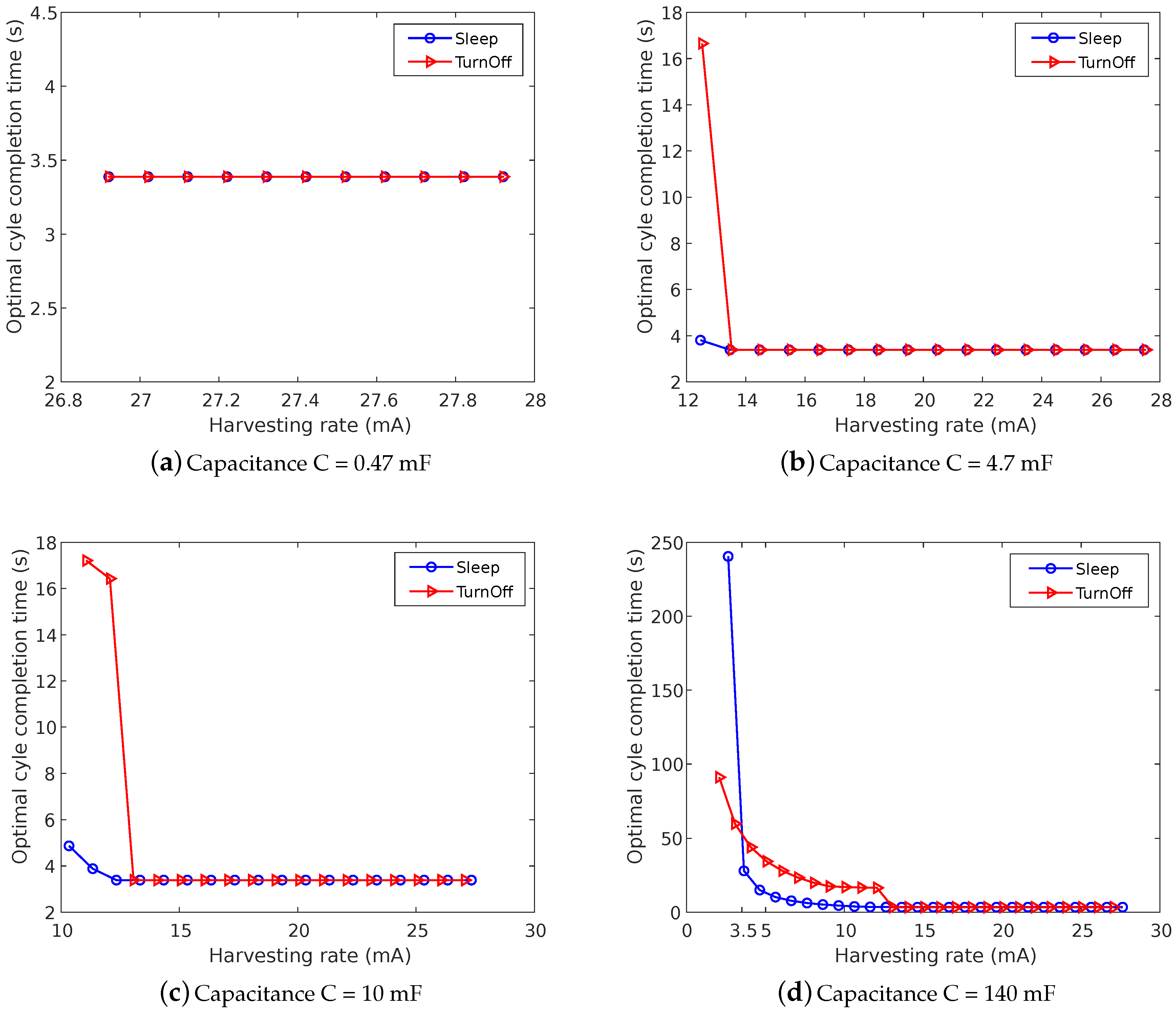
For the comparison between the defined approaches, we use the optimization algorithm described in Section 3.4 to calculate the minimum cycle completion time and associated optimal start voltage . We consider different ranges of capacitance and harvesting rates based on the results shown above. Figure 11 shows the minimum time the device needs to complete the full application cycle of tasks for different capacitor sizes considering both defined approaches. The Sleep approach shows the better minimum cycle time for capacitors of 4.7 and 10 mF, as shown in Figure 11b,c. The main reason for this behavior is the time that the device needs to turn on the radio again from the off mode. In contrast, using the Sleep approach, the device collects the energy during the sleep mode, which does not require the device to reconnect to the network after turning off and on the radio. As the harvesting rate increases, the device will have enough energy to perform all tasks without sleeping or turning off. In those scenarios, both approaches show the same performance.
For smaller capacitors such as 0.47 mF, the required harvesting rate is so high that both approaches can maintain a full capacitor almost at all times (except the Tx state which consumes 49.61 mA), resulting in the same performance in both cases. The most interesting case is shown in Figure 11d, which depicts the optimal application cycle time for a super capacitor of 140 mF. In this case, the TurnOff approach is able to outperform the Sleep approach, for harvesting rates below 3 mA. The main reason is the current consumption during the sleep mode, which is much higher compared to the off state and affects the minimum needed harvesting rate for task execution. As the harvesting rate increases (above 3.1 mA), the Sleep approach will show a better optimal time.
The optimal voltage depends greatly on the value of the required voltage that the device needs to reach in order to perform the specific tasks, but also on the voltage level where the device finishes the data transmission. Using the TurnOff approach, the optimal voltage is higher for lower harvesting rates (Figure 12b,c) because the required voltage for performing the tasks is around the initial value and the off time is shorter. Considering the Sleep approach, the optimal value depends greatly on the voltage level where the device ends with the data transmission task. In these cases, this value of voltage is around or even equal to the initial one, , for lower harvesting rates and the sleep time is shorter. After the device reaches the certain value of harvesting rate and the voltage can increase without sleeping or turning off, the optimal value is the one that can give the minimum possible time (3.388 s) for the full cycle of tasks.
For smaller capacitors such as 0.47 mF, the needed harvesting rate is much higher. In this case, the optimal voltage is the value which can give the minimum possible time of one cycle which is 3.388 s (Figure 12a). The device will start at the initial voltage which is higher than or even equal to all required voltage thresholds, eliminating the need to sleep or turn off. When larger capacitors are used (Figure 12d), the optimal voltage is low because it takes much longer to completely fill a large capacitor of 140 mF than a small 0.47-mF capacitor.
6. Conclusions
In this article, we studied the optimal parameters to schedule application tasks on battery-less IoT sensor devices. We studied the optimal voltage, in terms of minimum application cycle completion time, at which to perform sensing and transmission, considering different device and environmental parameters (i.e., capacitance and energy harvesting rate). We defined and analyzed two different approaches, allowing the device to either sleep or turn-off between two different application cycles.
Using an environment emulator and a real SODAQ ExpLoRer board, we validated our mathematical model. The deviation between results is 0.67% and it occurs due to small deviations in measured timings and current consumption of the different states. In addition, we showed that the capacitor size determines the minimum required harvesting rate and time of the full cycle. Our results show that a device using LoRaWAN Class A can measure the temperature and transmit its data at least once every 5 s if it can harvest at least 10 mA and uses a relatively small capacitor of 10 mF or less. In such cases, the Sleep approach provides the best results. At lower harvesting rates below 3 mA, it is necessary to turn off the device between application cycles and use a large super capacitor of at least 140 mF. In this case, the device is able to perform a temperature measurement and transmit once every 60 s at best. To support energy harvesting rates below 1 mA, an even larger capacitor would be needed.
The authors declare no conflict of interest.
Supplementary Materials
The following are available at https://www.mdpi.com/2079-9292/9/6/904/s1.
Author Contributions
Conceptualization, A.S., C.D., E.D.P., and J.F.; methodology, A.S., C.D., and J.F.; software, A.S., C.D., B.J., and J.F.; validation and experiments, A.S., C.D., D.S., and B.J.; writing, A.S., C.D., and J.F.; and supervision, C.D., E.D.P., and J.F. All authors have read and agreed to the published version of the manuscript.
Acknowledgments
Part of this research was funded by the Flemish FWO SBO S004017N IDEAL-IoT (Intelligent DEnse and Long range IoT networks) project and under by the University of Antwerp IOF funded project COMBAT (Time-Sensitive Computing on Battery-Less IoT Devices).
Conflicts of Interest
The authors declare no conflict of interest.
References
- Hester, J.; Sorber, J. The Future of Sensing is Batteryless, Intermittent, and Awesome. In Proceedings of the 15th ACM Conference on Embedded Network Sensor Systems, Delft, The Netherlands, 6–8 November 2017; Association for Computing Machinery: New York, NY, USA, 2017. [Google Scholar] [CrossRef]
- Delgado, C.; Sanz, J.M.; Famaey, J. On the Feasibility of Battery-Less LoRaWAN Communications using Energy Harvesting. In Proceedings of the IEEE Global Communications Conference (IEEE GLOBECOM), Waikoloa, HI, USA, 9–13 December 2019. [Google Scholar]
- Yang, F.; Thangarajan, A.S.; Joosen, W.; Huygens, C.; Hughes, D.; Ramachandran, G.S.; Krishnamachari, B. AsTAR: Sustainable Battery Free Energy Harvesting for Heterogeneous Platforms and Dynamic Environments. In Proceedings of the 2019 EWSN ’19 International Conference on Embedded Wireless Systems and Networks, Beijing, China, 25–27 February 2019; Junction Publishing: Boulder, CO, USA, 2019; pp. 71–82. [Google Scholar]
- Hester, J.; Scott, T.; Sorber, J. Ekho: Realistic and Repeatable Experimentation for Tiny Energy-Harvesting Sensors. In Proceedings of the 12th SenSys ’14 ACM Conference on Embedded Network Sensor Systems, Memphis, TN, USA, 3–6 November 2014; Association for Computing Machinery: New York, NY, USA, 2014; pp. 1–15. [Google Scholar] [CrossRef]
- Altinel, D.; Karabulut Kurt, G. Modeling of Multiple Energy Sources for Hybrid Energy Harvesting IoT Systems. IEEE Internet Things J. 2019, 6, 10846–10854. [Google Scholar] [CrossRef]
- Yildrim, K.S.; Majid, A.Y.; Patoukas, D.; Schaper, K.; Pawelczak, P.; Hester, J. InK: Reactive Kernel for Tiny Batteryless Sensors. In Proceedings of the 16th SenSys ’18 ACM Conference on Embedded Networked Sensor Systems, Shenzhen, China, 4–7 November 2018; Association for Computing Machinery: New York, NY, USA, 2018; pp. 41–53. [Google Scholar] [CrossRef]
- Bouguera, T.; Diouris, J.F.; Chaillout, J.J.; Jaouadi, R.; Andrieux, G. Energy Consumption Model for Sensor Nodes Based on LoRa and LoRaWAN. Sensors 2018, 18, 2104. [Google Scholar] [CrossRef] [PubMed] [Green Version]
- Alliance, L. LoRaWAN™ Specification v1.1; Technical Report; Lora Alliance: Fremont, CA, USA, 2017; Available online: https://lora-alliance.org/resource-hub/lorawantm-specification-v11 (accessed on 2 April 2020).
- Sherazi, H.H.R.; Imran, M.A.; Boggia, G.; Grieco, L.A. Energy Harvesting in LoRaWAN: A Cost Analysis for the Industry 4.0. IEEE Commun. Lett. 2018, 22, 2358–2361. [Google Scholar] [CrossRef] [Green Version]
- Loubet, G.; Takacs, A.; Gardner, E.; De Luca, A.; Udrea, F.; Dragomirescu, D. LoRaWAN Battery-Free Wireless Sensors Network Designed for Structural Health Monitoring in the Construction Domain. Sensors 2019, 19, 1510. [Google Scholar] [CrossRef] [PubMed] [Green Version]
- Karimi, M.; Kim, H. Energy Scheduling for Task Execution on Intermittently-Powered Devices. In Proceedings of the 9th Embedded Operating Systems Workshop (EWiLi2019), New York, NY, USA, 17 October 2019. [Google Scholar]
- Maeng, K.; Colin, A.; Lucia, B. Alpaca: Intermittent Execution without Checkpoints. Proc. ACM Program. Lang. 2017, 1. [Google Scholar] [CrossRef] [Green Version]
- Colin, A.; Lucia, B. Chain: Tasks and Channels for Reliable Intermittent Programs. In Proceedings of the 2016 OOPSLA 2016 ACM SIGPLAN International Conference on Object-Oriented Programming, Systems, Languages, and Applications, Amsterdam, Netherlands, 2–4 November 2016; Association for Computing Machinery: New York, NY, USA, 2016; pp. 514–530. [Google Scholar] [CrossRef] [Green Version]
- Majid, A.Y.; Donne, C.D.; Maeng, K.; Colin, A.; Yildirim, K.S.; Lucia, B.; Pawełczak, P. Dynamic Task-Based Intermittent Execution for Energy-Harvesting Devices. ACM Trans. Sens. Netw. 2020, 16. [Google Scholar] [CrossRef] [Green Version]
- Raza, U.; Kulkarni, P.; Sooriyabandara, M. Low Power Wide Area Networks: An Overview. IEEE Commun. Surv. Tutor. 2017, 19, 855–873. [Google Scholar] [CrossRef] [Green Version]
- Haxhibeqiri, J.; De Poorter, E.; Moerman, I.; Hoebeke, J. A survey of LoRaWAN for IoT: From technology to application. Sensors 2018, 18, 3995. [Google Scholar] [CrossRef] [PubMed] [Green Version]
- Van Loenen, J. Support Pages for SODAQ Hardware. 2019. Available online: https://support.sodaq.com/Boards/ExpLoRer/ (accessed on 2 April 2020).
- Sabovic, A.; Delgado, C.; Bauwens, J.; Poorter, E.D.; Famaey, J. Accurate Online Energy Consumption Estimation of IoT Devices Using Energest. In Advances on Broad-Band Wireless Computing, Communication and Applications, Proceedings of the 14th International Conference on Broad-Band Wireless Computing, Communication and Applications, BWCCA 2019, Antwerp, Belgium, 7–9 November 2019; Barolli, L., Hellinckx, P., Enokido, T., Eds.; Lecture Notes in Networks and Systems; Springer: Berlin, Germany, 2019; Volume 97, pp. 363–373. [Google Scholar] [CrossRef]
- De Mil, P.; Jooris, B.; Tytgat, L.; Catteeuw, R.; Moerman, I.; Demeester, P.; Kamerman, A. Design and Implementation of a Generic Energy-Harvesting Framework Applied to the Evaluation of a Large-Scale Electronic Shelf-Labeling Wireless Sensor Network. EURASIP J. Wirel. Commun. Netw. 2010, 2010. [Google Scholar] [CrossRef] [Green Version]
Figure 1.
Battery-less intermittent on/off behavior.

Figure 2.
Electrical circuit model of a battery-less IoT device.

Figure 3.
Sleep approach: LoRaWAN battery-less device sleeps between application tasks.

Figure 4.
TurnOff Approach: LoRaWAN battery-less device turns off between full cycles of application tasks.
Figure 4.
TurnOff Approach: LoRaWAN battery-less device turns off between full cycles of application tasks.

Figure 5.
LoRaWAN Class A device window timings.

Figure 6.
Measured current consumption for different states of the LoRaWAN device.

Figure 7.
Mathematical model validation using an environment emulator.

Figure 8.
The minimum needed harvesting rates for the considered approaches as a function of capacitance.
Figure 8.
The minimum needed harvesting rates for the considered approaches as a function of capacitance.

Figure 9.
Full cycle time for different voltages and harvesting rates considering different capacitor sizes for the Sleep approach.
Figure 9.
Full cycle time for different voltages and harvesting rates considering different capacitor sizes for the Sleep approach.

Figure 10.
Full cycle time for different voltages and harvesting rates considering different capacitor sizes, for the TurnOff approach.
Figure 10.
Full cycle time for different voltages and harvesting rates considering different capacitor sizes, for the TurnOff approach.

Figure 11.
Optimal cycle completion time for different capacitance including all considered approaches.
Figure 11.
Optimal cycle completion time for different capacitance including all considered approaches.

Figure 12.
Optimal cycle start voltage for different capacitance including all considered approaches.
Figure 12.
Optimal cycle start voltage for different capacitance including all considered approaches.


Table 1.
Current consumption and time values of SODAQ ExpLoRer board.
| State | Current Consumption | Time Values |
|---|---|---|
| Temperature measurement | 17 mA | 0.008 s |
| Tx | 49.61 mA | 0.05 s |
| Idle 1 | 17.13 mA | 0.92 s |
| First reception window | 27.57 mA | 0.09 s |
| Idle 2 | 17.12 mA | 0.92 s |
| Second reception window | 27.73 mA | 0.27 s |
| Idle 3 | 16.92 mA | 1.18 s |
| Radio-MCU Start-up | 13 mA | 13 s |
| Sleep | 3.44 mA | - |
| Off | 0.0004 mA | - |
Table 2.
Experimental setup.
| Parameter | Symbol | Value |
|---|---|---|
| Min Voltage | 2.2 V | |
| Max Voltage | E | 3.3 V |
| Capacitance | C | (0.47, 4.7, 10, 140) mF |
| Harvesting Rate | 2.06–28 mA | |
| Spreading Factor | SF | 7 |
| Payload size | PS | 8B |
© 2020 by the authors. Licensee MDPI, Basel, Switzerland. This article is an open access article distributed under the terms and conditions of the Creative Commons Attribution (CC BY) license (http://creativecommons.org/licenses/by/4.0/).
Share and Cite
MDPI and ACS Style
Sabovic, A.; Delgado, C.; Subotic, D.; Jooris, B.; De Poorter, E.; Famaey, J. Energy-Aware Sensing on Battery-Less LoRaWAN Devices with Energy Harvesting. Electronics 2020, 9, 904. https://doi.org/10.3390/electronics9060904
AMA Style
Sabovic A, Delgado C, Subotic D, Jooris B, De Poorter E, Famaey J. Energy-Aware Sensing on Battery-Less LoRaWAN Devices with Energy Harvesting. Electronics. 2020; 9(6):904. https://doi.org/10.3390/electronics9060904
Chicago/Turabian StyleSabovic, Adnan, Carmen Delgado, Dragan Subotic, Bart Jooris, Eli De Poorter, and Jeroen Famaey. 2020. "Energy-Aware Sensing on Battery-Less LoRaWAN Devices with Energy Harvesting" Electronics 9, no. 6: 904. https://doi.org/10.3390/electronics9060904
Note that from the first issue of 2016, this journal uses article numbers instead of page numbers. See further details here.