Automatic Fault-Tolerant Control of Multiphase Induction Machines: A Game Changer


Department of Electrical Engineering, Engineering School, University of Malaga, 29071 Malaga, Spain
*
Author to whom correspondence should be addressed.
Electronics 2020, 9(6), 938; https://doi.org/10.3390/electronics9060938
Submission received: 1 May 2020
/
Revised: 26 May 2020
/
Accepted: 30 May 2020
/
Published: 4 June 2020
(This article belongs to the Special Issue Machine Fault Detection and Fault-Tolerant Control)
Abstract
:Until very recently, the fault tolerance in multiphase electric drives could only be achieved after fault localization and a subsequent modification of the control scheme. This scenario was profoundly shaken with the appearance of the natural fault tolerance, as the control reconfiguration was not required anymore. Even though the control strategy was highly simplified, it was still necessary to detect the open-phase fault (OPF) in order to derate the electric drive and safeguard its integrity. This work goes one step beyond and suggests the use of an automatic fault-tolerant control (AFTC) that also avoids the detection of the OPF. The AFTC combines the natural fault-tolerant capability with a self-derating technique, finally obtaining a hardware-free software-free fault tolerance. This achievement changes completely the rules of the game in the design of fault-tolerant drives, easing at the same time their industrial application. Experimental results confirm in a six-phase induction motor (IM) drive that the proposed AFTC provides a simple and safe manner to add further reliability to multiphase electric drives.
1. Introduction
The advantages of multiphase drives over their three-phase counterparts are nowadays well known, exploited and applied [1]. In addition to the possibility of activating exclusive modes of operation [2], such as the enhanced braking capability [3], the two most attractive features are likely the capability to enhance the efficiency and reliability of the electric drive [4]. The post-fault operation is especially critical in applications where security is a main concern (e.g., aircraft, electric vehicles), but it is also appreciated when the shut-down of the electric machine involves a significant economic impact (e.g., wind energy conversion systems) [5].
Standard three-phase machines can only achieve a satisfactory post-fault operation with the insertion of additional hardware [6]. Instead, multiphase machines provide a hardware-free fault tolerance taking advantage of their inherent redundancy [7]. Despite the lack of additional hardware, the enhanced reliability is obtained at the expense of a much higher control algorithm complexity. First of all, it is mandatory to detect and localize the open-phase fault (OPF). Secondly, the current references must be modified according to the fault scenario. Thereby, it is necessary to store different sets of current references and select the one that corresponds to the specific fault scenario [4]. Thirdly, the current controllers must change their structure. This stage varies depending on the control approach. For the sake of example, in field oriented control (FOC) the x-y proportional-integral (PI) current controllers are typically converted into proportional-resonant controllers (PR) in order to cope with the nonconstant nature of the x-y current references after the fault occurrence [7]. Finally, the drive needs to be derated to avoid over-currents and safeguard the integrity of the electric drive [4]. To sum up, the fault tolerance traditionally requires four stages: stage one (detection and localization), stage two (modification of the current references), stage three (control reconfiguration) and stage four (derating). It can be concluded that, although feasible, the improved reliability is obtained with a rather high software complexity.
In this context, some recent works have suggested the use of a control scheme that remains valid both before and after the fault occurrence. This alternative approach skips the aforementioned stages two and three and has been baptised as natural fault tolerance, tested in six-phase systems with predictive strategies [8] and FOC [9], and also extended to nine-phase systems [10]. The core idea in these works is to maintain the x-y current control in open-loop mode in order to avoid the conflict with d-q controllers in post-fault situation. While this key feature is implemented in direct controllers using virtual voltage vectors [8], FOC simply deactivates the closed-loop x-y current controllers after the fault occurrence [9]. Although the higher simplicity of the natural approach was a tipping point in the design of fault-tolerant regulation strategies for multiphase drives, stages one and four were still mandatory to protect the machine and converter from eventual over-currents. Since the derating of the drive does not require the knowledge of the specific phases under OPF, a simplified version of stage one was suggested in [11]. However, the determination of the fault scenario and the subsequent derating were still required [11].
This work completes the simplification of the fault-tolerant control by suggesting a procedure for the self-derating of the multiphase electric drive. The current limits are set in a variable manner; therefore, the maximum current values are immediately changed after the fault occurrence. The proposed procedure guarantees that the stator copper losses are below rated values both in pre and post-fault situations. Moreover, since this procedure is automatic, stage four is no longer required. Similarly, stage one can also be omitted from an operational perspective: detection can be useful for diagnosis purposes, but not to adapt the post-fault operation [12].
By combining the natural fault-tolerant strategy with the self-derating procedure, the electric drive becomes fault-tolerant with no action at all. While the natural approach avoids stages two and three, the self-derating procedure skips stages one and four. This software-free regulation strategy will be referred from now on as automatic fault-tolerant control (AFTC). Compared to previous works, this proposal can be regarded as the first AFTC strategy because all other strategies require some kind of software modification, either in the control structure itself or in the setting of the operating limits. In few words, while multiphase machines have a potential hardware-free fault-tolerant capability, the suggested AFTC achieves this enhanced reliability in a software-free fashion. The result brings a highly attractive feature for industry because it provides simple means to empower the electric drive with a higher robustness. The paper is structured so that the background on FOC for six-phase drives is introduced in Section Two, the proposed AFTC strategy is described in Section Three, the experimental results are discussed in Section Four and the main conclusions are summarized in Section Five.
2. Field Oriented Control in Six-Phase IM Drives
2.1. Generalities of Six-Phase Electric Drives
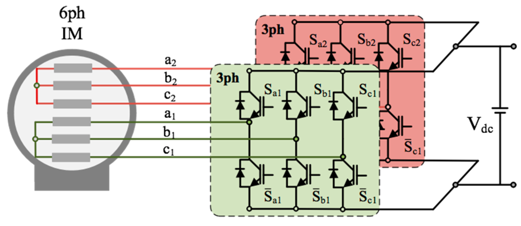
An asymmetrical six-phase induction motor (IM) and a dual three-phase two-level voltage source converter (VSC) were employed in this study (Figure 1). Although it is possible to model the six-phase IM in phase variables (), it was more convenient for regulation purposes to employ the vector space decomposition (VSD) approach via the application of the current invariant generalized Clarke transformation:
The distributed-winding IM could then be modelled in VSD variables [1], where the different components have a clearer meaning: α-β currents generate the flux/torque, whereas x-y currents are just parasitic currents that flow through the stator of the IM. As in three-phase drives, the α-β currents were typically transformed into a synchronous reference frame using the Park rotational transformation, whereas the x-y currents were transformed with the inverse of this transformation matrix:
where θs is the instantaneous position of the reference frame that is obtained from the measured stator currents and rotor parameters [1]:
2.2. Natural Fault-Tolerant Indirect Rotor Field Oriented Control (IRFOC)
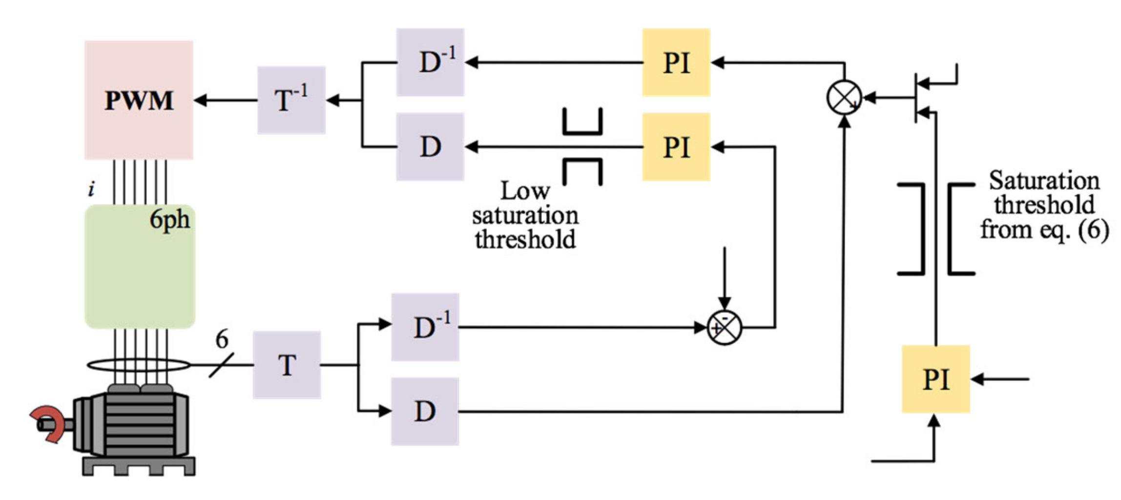
In multiple three-phase machines with isolated neutral points, the standard indirect rotor field oriented control (IRFOC) strategy usually employs a control structure based on the utilization of one outer PI speed controller and 2n/3 PI stator current controllers. This implies that four VSD currents are under control in a six-phase machine: the d-current regulates the flux production, the q-current regulates the torque production, and the - currents are simply driven to zero in order to reduce stator copper losses (Figure 2).
When an OPF occurs, the phase current cannot flow through the damaged phase, appearing as a new restriction in the system. For example, if an OPF occurs in phase , the new restriction in the system will be [8]:
It can be deduced from Equation (4) that α-β and x-y planes are no longer independent in post-fault situation, hence it becomes impossible to satisfy the x-current reference (set to zero) and the α-current reference (set to a nonzero value). Therefore, it becomes clear that α and x controllers are seeking incompatible goals. This conflict implies that x-y controllers will disturb α-β currents, ultimately affecting the torque and speed regulation of the electric machine.
The traditional solution has been to modify the stator current references (setting ), using resonant controllers in the form of double PI regulators. Nevertheless, this requires the detection/localization of the fault and a fast control reconfiguration in order to avoid undesirable transients after the fault occurrence [4].
An alternative solution to evade the conflict between α-β and x-y controllers is to simply deactivate the closed-loop regulation of the x-y currents [9]. The need to modify the current references (stage 2) obviously disappears, and the control reconfiguration (stage 3) can also be circumvented if the activation of the open-loop x-y control is naturally achieved. This can be accomplished if the closed-loop x-y control is eliminated in healthy operation, but this solution can lead to suboptimal solutions in the presence of machine asymmetries or nonideal effects [9]. For this reason, it is suggested in [9] to set a low saturation threshold for the x-y PI controllers (Figure 2). This procedure maintains the x-y controllers in healthy operation and automatically deactivates them after the OPF occurrence.
Even though the natural fault-tolerant control avoids stages 2 and 3, it is still necessary to detect the fault and identify the fault scenario (stage 1) in order to derate the drive (stage 4) and safeguard the drive integrity [11]. The next section reveals how to get rid of these remaining stages, so that the fault-tolerant control becomes fully automatic.
3. Automatic Fault-Tolerant Control (AFTC)
After OPFs occur, the number of active phases is reduced. In order to maintain the same operating point as in healthy situation, the rms value of phase currents must increase. This rise of the post-fault phase currents results in higher stator copper losses, eventually causing severe damage if the winding temperature increases above the insulation class of the winding. For this reason, a derating is mandatory in order to avoid an overheating of the motor [4].
Since the d-current is typically set to a constant value in the base-speed region, the derating can be done by simply defining a threshold for the q-current (termed in what follows) [13]. This constant value for the saturation of the q-current is valid in prefault operation because x-y currents are regulated to zero. Nevertheless, after the fault occurrence the x-y currents are no longer null, Equation (4), and the value of becomes excessive.
Traditionally, it is suggested to change the value of after the fault occurrence according to the specific fault scenario [13]. This procedure is completely logical in fault-tolerant control schemes with reconfiguration [1], because the fault scenario needs to be identified in any case. Consequently, the efforts to change the value of are minimum. However, in natural fault-tolerant approaches the detection and localization of the faulty phases are not required for control purposes, hence the derating of the drive becomes the only reason to maintain stage 1 (fault localization). It is in this context where a self-derating would avoid not only stage 4, but also stage 1. Aiming to further simplify the fault tolerance, the value of needs to be variable without the need to detect or localize the fault. In other words, the saturation of the q-current should vary after the OPF even when the drive does not know that the fault has occurred.
For this purpose, it is necessary to consider the rms value of phase currents, calculated from VSD variables as [3]:
where - currents have a close-to-zero value in a healthy situation and the d-current is fixed at its nominal value, so variations of the rms value of phase currents are solely due to the q-current. On the other hand, the maximum rms phase current is determined by the winding rated current ().
Setting the limit and replacing in Equation (5), an expression of the maximum q-current as a function of other VSD variables can be obtained:
When an OPF occurs, the - currents immediately have a nonzero value because of the fault restriction, Equation (4), hence reducing automatically the maximum value of the q-current. As it can be deduced from Equation (6), the higher the value of the - currents, the lower is the threshold . Taking into account that the - currents rise after the OPF occurrence without any control action because it is a physical restriction, it follows that the derating (i.e., ) is applied in an automatic manner. Furthermore, the variable threshold from Equation (6) guarantees that the post-fault stator copper losses are below rated values.
The integration of the self-derating procedure into the natural IRFOC scheme can be done by including the variable saturation from Equation (6) at the output of the PI speed controller, as it is depicted in Figure 2. The variable nature of the maximum q-current value implies that the drive automatically sets different current limits in pre and post-fault situations in order to prevent any damage. It is worth highlighting that PI control parameters, as well as the control structure, did not change after the fault occurrence. The addition of the self-derating procedure shown in Figure 2 completed the proposed AFTC and allows the software-free fault-tolerant control of the six-phase IM drive.
Finally, it is worth noting that self-derating was included as a saturation threshold for the PI speed controller, therefore this procedure can also be successfully applied to other current control schemes, such as model predictive control (MPC) or direct torque control (DTC) [14].
4. Experimental Results
4.1. Test Bench
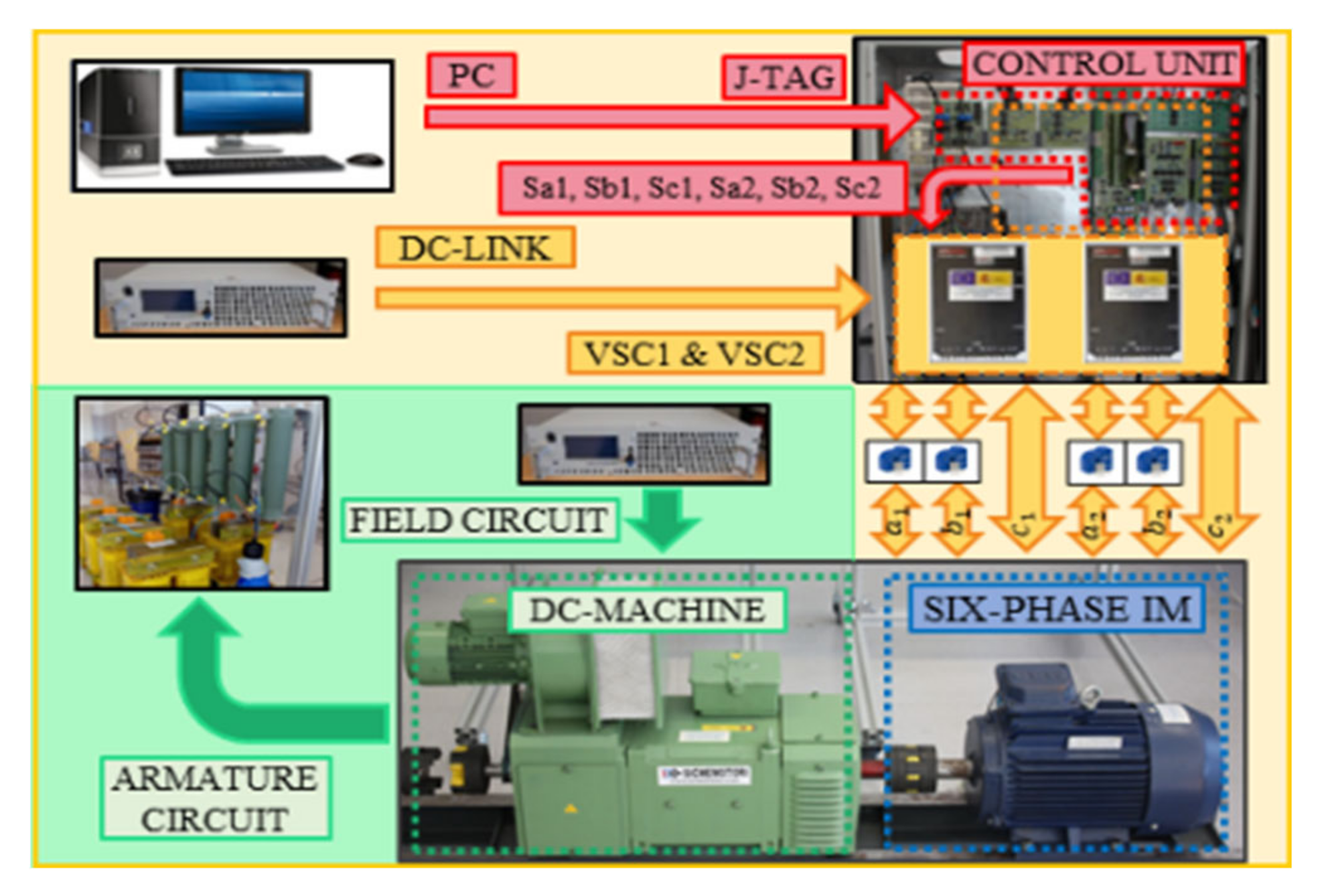
Figure 3 shows the employed test bench, where the six-phase IM was driven by two conventional two-level three-phase VSCs (Semikron SKS22F modules (Semikron, Nuremberg, Germany)). Parameters of the aforementioned six-phase IM have been obtained using ac-time domain and stand-still with inverter supply tests (see Table 1). The VSCs are supplied by a single 300 V DC power source and the control actions are performed by a digital signal processor (TMS320F28335 from Texas Instruments, (TI, Dallas, TX, USA)). Phase currents and speed measurements were obtained using four hall-effect sensors (LEM LAH 25-NP (LEM, Bourg-la-Reine, France)) and a digital encoder (GHM510296R/2500 (Sensata, Attleboro, MA, USA)). The six-phase IM is loaded coupling its shaft to a dc machine. A variable passive R passive load was connected to the dc-machine and, consequently, the load torque was speed-dependent. On the other hand, the OPFs have been provoked using a controllable relay board implemented between the inverter and the machine.
4.2. Experimental Results
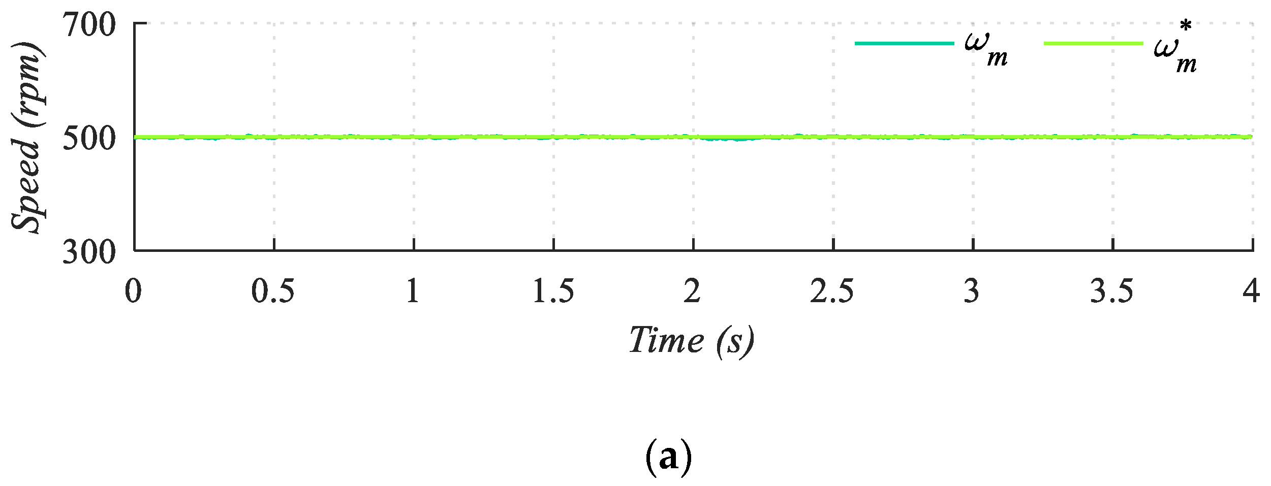
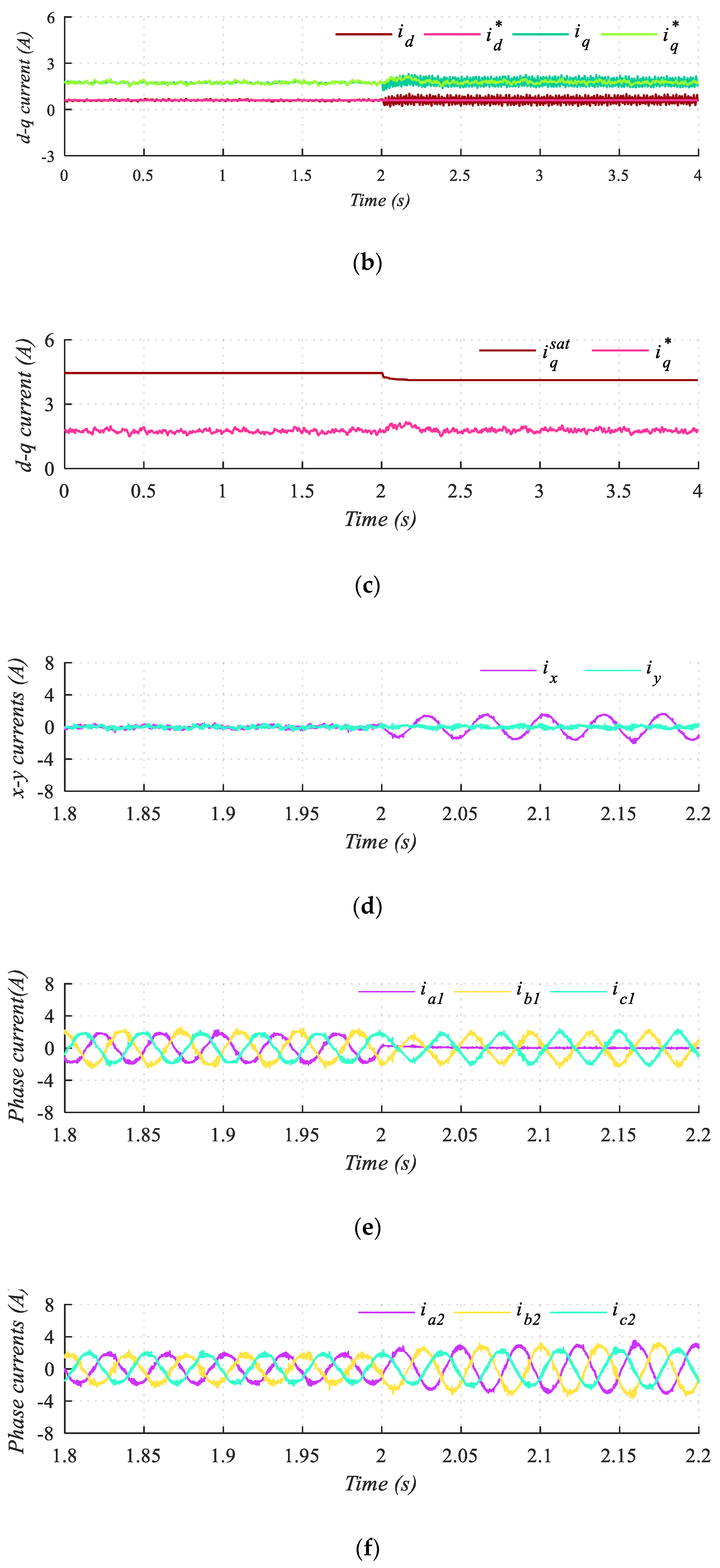
Test 1 is designed to verify the response of the self-derating algorithm when the operating point is achievable in post-fault situation (Figure 4). The reference speed is fixed to 500 rpm and the load torque was equal to 1 Nm. At t = 2s an OPF is forced in phase (Figure 4e), highlighting the post-fault restriction, Equation (4), in the system (Figure 4d).
Despite the OPF occurrence, the speed and d-q current tracking was successfully done, obtaining a similar performance as in reconfigured control approaches [9]. The maximum q-current was reduced after the fault from 4.48 A to 4.18 A, as it can be observed in Figure 4f. Nonetheless, its value remained higher than the actual q-current reference, therefore the saturation was not reached, and the dynamics of the drive were not affected. As expected from Equation (4), the post-fault x-current is no longer null, reducing the value of as a result of the self-derating from Equation (5). In the case of test 1, the modification of the maximum achievable q-current did not affect the control performance, but in other operating conditions this saturation can be reached, as it is illustrated in the next test.
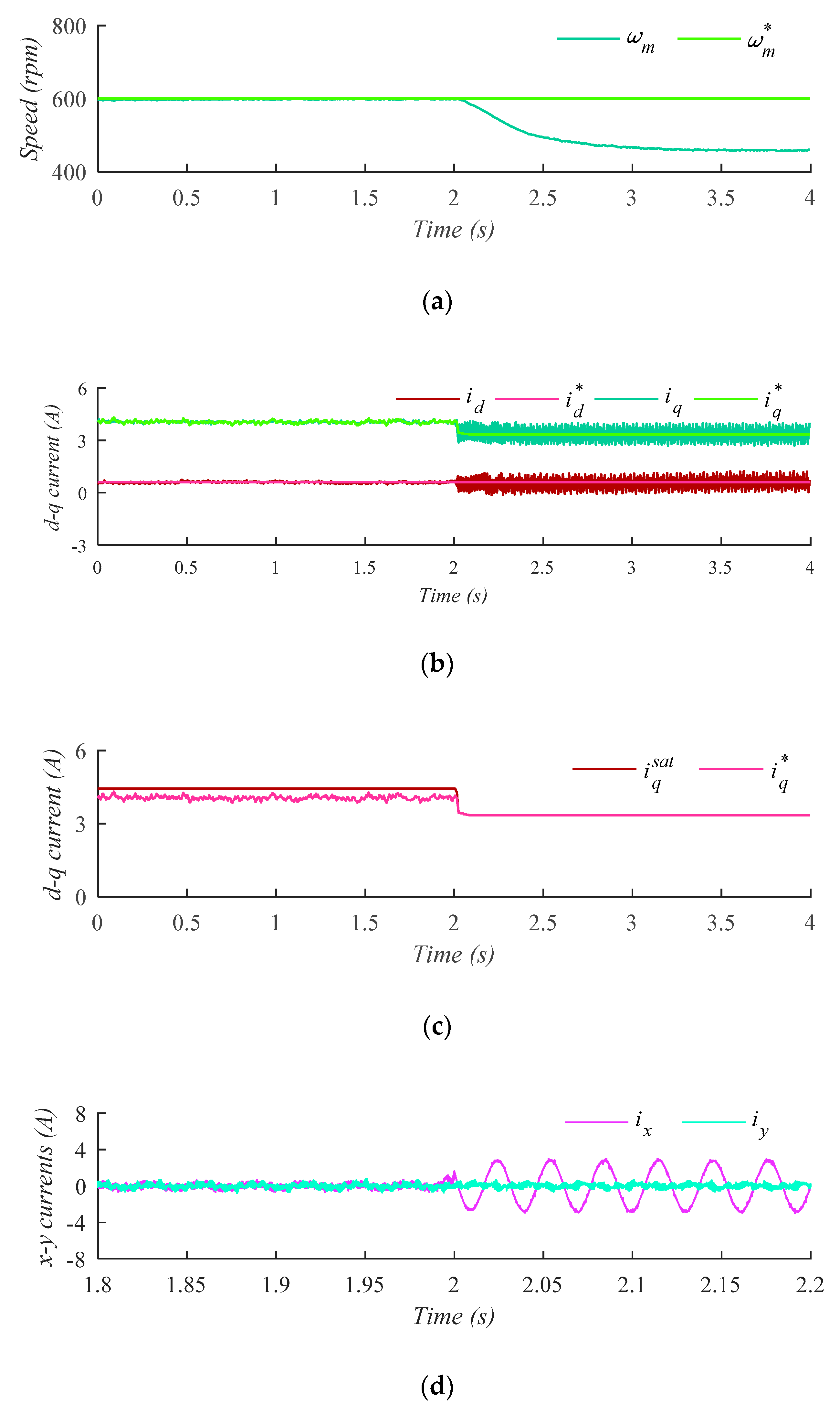
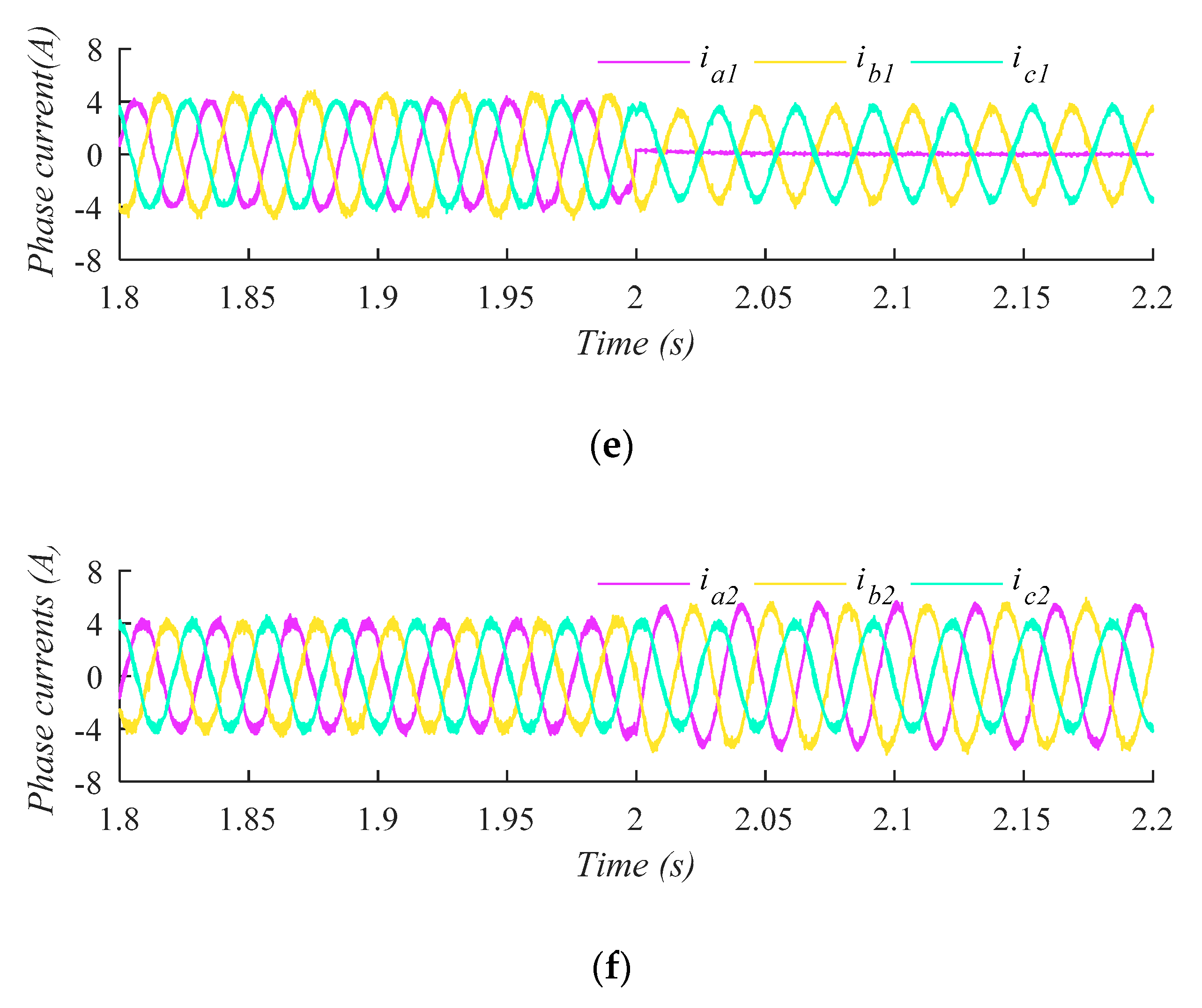
In test 2, the operating point after OPF is not reachable if the integrity of the system is to be safeguarded. Therefore, the automatic fault-tolerant approach forces the control to reduce the motor speed in order satisfy the prevention requirements (Figure 5). The reference speed was set to 600 rpm and the load torque was increased up to 4.6 Nm. As in test 1, an OPF was provoked at time t = 2 s in phase (Figure 5e), so that the current cannot flow through the damaged phase. When the OPF occurs, the maximum q-current was reduced from 4.43 A to 3.45 A, suffering a reduction of 22.12% (Figure 5c). After the derating, the value of dropped below the prefault value of the q-current, therefore saturation took place. The limitation of the q-current (Figure 5b) after the saturation reduced the torque production and deactivated the closed-loop speed control. The torque was then regulated in open-loop mode and the motor speed consequently dropped down to 458.5 rpm (Figure 5a). The response of the self-derating algorithm is depicted in Figure 5f, showing a fast reduction of after the fault occurrence. The automatic derating (i.e., reduction of ) mirrors the increase of x-y currents immediately after the OPF, as it can be expected from the definition of the saturation threshold in Equation (6). In any case, regardless of the post-fault derating value, it can be observed in Figure 4 and Figure 5 that the current and speed control after the OPF is done with a similar performance as in the reconfigured approach [9].
To sum up, the proposed AFTC strategy allows a satisfactory post-fault speed regulation of the six-phase drive both when the derating saturates the q-current (Test 2) and when the value of is not reached (Test 1). This enhanced reliability is provided with no additional hardware and with no control action at all.
5. Conclusions
Redundancy in multiphase systems can enhance the reliability of the electric drive without additional hardware. This attractive capability has been so far hindered by the mandatory need to add further complexity to the control stage. The proposed automatic fault-tolerant control (AFTC) shows however that it is possible to achieve a satisfactory post-fault performance with no action after the OPF occurrence. This software-free approach is obtained with the inclusion of a self-derating procedure into a natural fault-tolerant control strategy.
Experimental results confirm the self-derating capability of the AFTC, providing a similar post-fault performance as in reconfigured control approaches. The universal nature of AFTC allows the use of a single control scheme for pre and post-fault situations, hence avoiding the fault detection and control reconfiguration. The simplicity and universality of AFTC are key features that foretell a good prospect for industry application where reliability is a must.
Author Contributions
Conceptualization, M.J.D.; methodology, I.G.-P.; software, A.G.-P. and J.J.A.; validation, J.J.A. and A.G.-P.; formal analysis, A.G.-P.; investigation, A.G.-P.; resources, I.G.-P.; data curation, J.J.A.; writing—original draft preparation, J.J.A. and A.G.-P.; writing—review and editing, M.J.D. and I.G.-P.; visualization, A.G.-P.; supervision, M.J.D. and I.G.-P.; project administration, M.J.D. and I.G.-P.; funding acquisition, M.J.D. and I.G.-P. All authors have read and agree to the published version of the manuscript.
Funding
This research was funded by the Spanish Government under the Plan Estatal 2017–2020 with the reference RTI2018-096151-B-I00.
Acknowledgments
The authors would like to thank the Spanish Government.
Conflicts of Interest
The authors declare no conflict of interest.
References
- Duran, M.J.; Levi, E.; Barrero, F. Multiphase Electric Drives: Introduction. Wiley Encycl. Electr. Electron. Eng. 2017, 1–26. [Google Scholar] [CrossRef]
- Levi, E. Advances in Converter Control and Innovative Exploitation of Additional Degrees of Freedom for Multiphase Machines. IEEE Trans. Ind. Electron. 2015, 63, 433–448. [Google Scholar] [CrossRef]
- Duran, M.J.; Gonzalez-Prieto, I.; Barrero, F.; Levi, E.; Zarri, L.; Mengoni, M. A simple Braking Method for Six-Phase Induction Motor Drives with Unidirectional Power Flow in the Base-Speed Region. IEEE Trans. Ind. Electron. 2017, 64, 6032–6041. [Google Scholar] [CrossRef] [Green Version]
- Munim, W.; Duran, M.J.; Che, H.S.; Bermudez, M.; Prieto, I.G.; Rahim, N.A. A Unified Analysis of the Fault Tolerance Capability in Six-Phase Induction Motor Drive. IEEE Trans. Power Electron. 2016, 32, 7824–7836. [Google Scholar] [CrossRef]
- Yaamasu, V.; Dekka, A.; Duran, M.J.; Kouro, S.; Wu, B. Permanent Magnet Synchronous Generator-based Wind Energy Conversion Systems: Survey on Power Converters and Controls. IET Electr. Power Appl. 2017, 11, 956–968. [Google Scholar] [CrossRef]
- Tousizadeh, M.; Che, H.S.; Selvaraj, J.; Rahim, N.A.; Ooi, B.-T. Performance Comparison of Fault-Tolerant Three-Phase Induction Motor Drives Considering Current and Voltage Limits. IEEE Trans. Ind. Electron. 2019, 66, 2639–2648. [Google Scholar] [CrossRef]
- Tani, A.; Zarri, L.; Casadei, D.; Mengoni, M.; Serra, G. Control of Multiphase Induction Motors with an Odd Number of Phases Under Open-circuit Phase Faults. IEEE Trans. Power Electron. 2011, 27, 565–577. [Google Scholar]
- Gonzalez-Prieto, I.; Duran, M.J.; Bermudez, M.; Barrero, F.; Martin, C. Assessment of Virtual-Voltage-based Model Predictive Controllers in Six-phase Drives under Open-Phase Faults. IEEE J. Emerg. Sel. Top. Power Electron. 2019, 1. [Google Scholar] [CrossRef]
- Gonzalez-Prieto, I.; Duran, M.J.; Garcia-Entrambasaguas, P.; Bermudez, M. Field Oriented Control of Multiphase Drives with Passive Fault Tolerance. IEEE Trans. Ind. Electron. 2019. [Google Scholar] [CrossRef]
- Drozdowski, P.; Cholewa, D. Natural Fault Tolerance of a Nine-Phase Induction Motor Drive Operating at Variable Frequency and Switched Supply Sequence. In Proceedings of the 15th Selected Issues of Electrical Engineering and Electronics (WZEE), Zakopane, Poland, 8–10 December 2019. [Google Scholar] [CrossRef]
- Garcia-Entrambasaguas, P.; Gonzalez-Prieto, I.; Duran, M.J. Single index Open-phase Fault Detection Method for Six-phase Electric Drives. IEEE Trans. Ind. Electron. 2019, 1. [Google Scholar] [CrossRef]
- Prieto, I.G.; Duran, M.J.; Rios-Garcia, N.; Barrero, F.; Martin, C. Open-Switch Fault Detection in Five-Phase Induction Motor Drives Using Model Predictive Control. IEEE Trans. Ind. Electron. 2018, 65, 3045–3055. [Google Scholar] [CrossRef]
- Abdel-Khalik, A.S.; Masoud, M.; Ahmed, S.; Massoud, A. Calculation of derating factors based on steady-state unbalanced multiphase induction machine model under open phase(s) and optimal winding currents. Electr. Power Syst. Res. 2014, 106, 214–225. [Google Scholar] [CrossRef]
- Barrero, F.; Bermudez, M.; Duran, M.J.; Salas, P.; Gonzalez-Prieto, I. Assessment of a Universal Reconfiguration-less Control Approach in Open-Phase Fault Operation for Multiphase Drives. Energies 2019, 12, 4698. [Google Scholar] [CrossRef] [Green Version]
Figure 1.
Six-phase drive topology.

Figure 2.
Proposed automatic fault-tolerant control (AFTC) scheme.

Figure 3.
Employed test bench.

Figure 4.
Test 1. Post-fault response when operation point can be maintained. From top to bottom: (a) motor speed, (b) d-q currents, (c) maximum q and q reference current, (d) x-y currents, (e) set 1 of phase currents and (f) set 2 of phase currents.
Figure 4.
Test 1. Post-fault response when operation point can be maintained. From top to bottom: (a) motor speed, (b) d-q currents, (c) maximum q and q reference current, (d) x-y currents, (e) set 1 of phase currents and (f) set 2 of phase currents.


Figure 5.
Test 2. Post-fault response when operation point cannot be achievable. From top to bottom: (a) motor speed, (b) d-q currents, (c) maximum q and q reference current, (d) x-y currents, (e) set 1 of phase currents and (f) set 2 of phase currents.
Figure 5.
Test 2. Post-fault response when operation point cannot be achievable. From top to bottom: (a) motor speed, (b) d-q currents, (c) maximum q and q reference current, (d) x-y currents, (e) set 1 of phase currents and (f) set 2 of phase currents.


Table 1.
Induction machine drive parameters.
| Parameter | Value |
| Power (kW) | 0.8 |
| 4.2 | |
| 2 | |
| 420 | |
| 1.5 | |
| 55 | |
| 1000 | |
| 4.5 | |
| 0.6 |
© 2020 by the authors. Licensee MDPI, Basel, Switzerland. This article is an open access article distributed under the terms and conditions of the Creative Commons Attribution (CC BY) license (http://creativecommons.org/licenses/by/4.0/).
Share and Cite
MDPI and ACS Style
Gonzalez-Prieto, A.; Aciego, J.J.; Gonzalez-Prieto, I.; Duran, M.J. Automatic Fault-Tolerant Control of Multiphase Induction Machines: A Game Changer. Electronics 2020, 9, 938. https://doi.org/10.3390/electronics9060938
AMA Style
Gonzalez-Prieto A, Aciego JJ, Gonzalez-Prieto I, Duran MJ. Automatic Fault-Tolerant Control of Multiphase Induction Machines: A Game Changer. Electronics. 2020; 9(6):938. https://doi.org/10.3390/electronics9060938
Chicago/Turabian StyleGonzalez-Prieto, Angel, Juan J. Aciego, Ignacio Gonzalez-Prieto, and Mario J. Duran. 2020. "Automatic Fault-Tolerant Control of Multiphase Induction Machines: A Game Changer" Electronics 9, no. 6: 938. https://doi.org/10.3390/electronics9060938
Note that from the first issue of 2016, this journal uses article numbers instead of page numbers. See further details here.