Article

Hybrid Current-Mode Control of PSFB Converter to Compensate Slew Interval and Prevent Magnetic Saturation of Transformers

1
Department of Electronic Engineering, Korea National University of Transportation, Chungju-si 27469, Korea
2
Department of Transportation System Engineering, Korea National University of Transportation, Uiwang-si 16106, Korea
*
Author to whom correspondence should be addressed.
Electronics 2020, 9(9), 1395; https://doi.org/10.3390/electronics9091395
Submission received: 22 July 2020 / Revised: 17 August 2020 / Accepted: 25 August 2020 / Published: 28 August 2020
(This article belongs to the Special Issue Advances in Power Electronics for Transportation Electrification)

Abstract

:
This paper proposes a newly developed hybrid current-mode control (HCMC) method for phase-shifted full-bridge (PSFB) converters. Generally, PSFB converters have been widely used in various DC-DC power applications owing to their ease of control and low switching losses. However, the transformer can be saturated by volt-second imbalance of the magnetizing inductance. Therefore, a blocking capacitor can be used in series with the transformer, or peak current-mode control methods with slope compensation can be applied, to prevent transformer saturation. However, blocking capacitors increase the material cost and make the power stage bulky. Moreover, the overcompensation by slope compensation methods delays the control response. This paper proposes a hybrid current-mode control (HCMC) for PSFB converters to solve these problems. A blocking capacitor and slope compensation are not required in the proposed HCMC method for PSFB converters. The proposed HCMC method has no transformer saturation and output response delay, and the efficacy of this method has been verified through simulations and experiments.

1. Introduction

Electric vehicles have attracted increasing attention owing to the worldwide depletion of fossil fuels and increasing environmental pollution [1,2,3]. Furthermore, the proliferation of rechargeable electric vehicles, such as plug-in hybrid electric vehicles and battery electric vehicles, has coincided with a broadening scope of research on on-board chargers (OBCs) [4,5,6,7,8]. Although OBCs are currently being used as rechargeable batteries, super-capacitors are expected to enable quick energy recharging at regeneration. However, as the OBC is installed in the vehicle, a transformer-isolated converter is primarily used for safety purposes. Among the types of transformer-isolated converters, phase-shifted full-bridge (PSFB) converters, shown in Figure 1, have been employed in numerous fields that require an isolated power supply because of their ease of control and low switching losses [9,10,11]. Unlike hard-switching full-bridge converters, PSFB converters operate with a phase difference between the lagging and leading legs, thus enabling zero-voltage switching (ZVS) operation. Furthermore, controller design is easy because the converter model resembles a buck converter [12].
However, PSFB converters experience transformer saturation due to the primary-side current imbalance [13,14]. Significant damage is incurred to the power circuit when the transformer is saturated; therefore, blocking capacitors are connected in series with the transformer to prevent transformer saturation. However, adding a blocking capacitor increases the size of the power stage and overall cost [15,16,17].
Another method to prevent transformer saturation is peak current-mode control (PCMC). Although PCMC has an additional advantage of a fast response, a sub-harmonic oscillation is generated by the inductor current if the duty ratio exceeds 0.5 [18,19]. The slope compensation technique is generally used to resolve this problem [20,21,22], but overcompensation may result in a response delay. Thus, a hybrid current-mode control (HCMC) was employed in this study to mitigate the aforementioned limitations. HCMC implements peak and valley current controls according to the input and output voltages and switching frequency to enable fast-response capability. This prevents the overcompensation-related response delay that typically occurs due to the operating slope compensation in the peak current mode. HCMC has been applied to boost converters, where the peak and valley currents are easily detected [23]. However, when HCMC is applied to PSFB converters, it is difficult to detect the valley current from a DC-link-side current sensor normally used in PCMC. Thus, in this study, HCMC was applied to a PSFB converter using a current sensor that detects the AC-side value of the primary-side current. The proposed HCMC for PSFB converters has no magnetic current saturation, and it does not require slope compensation. The proposed controller was verified through simulation and experiments. In Section 2, the primary-side current imbalance problem of PSFB converters is presented. In Section 3, conventional methods to prevent current imbalance are discussed. In Section 4, the proposed HCMC for PSFB converters is described. Section 5 presents the simulation and experimental results. Finally, the conclusions are presented in Section 6.

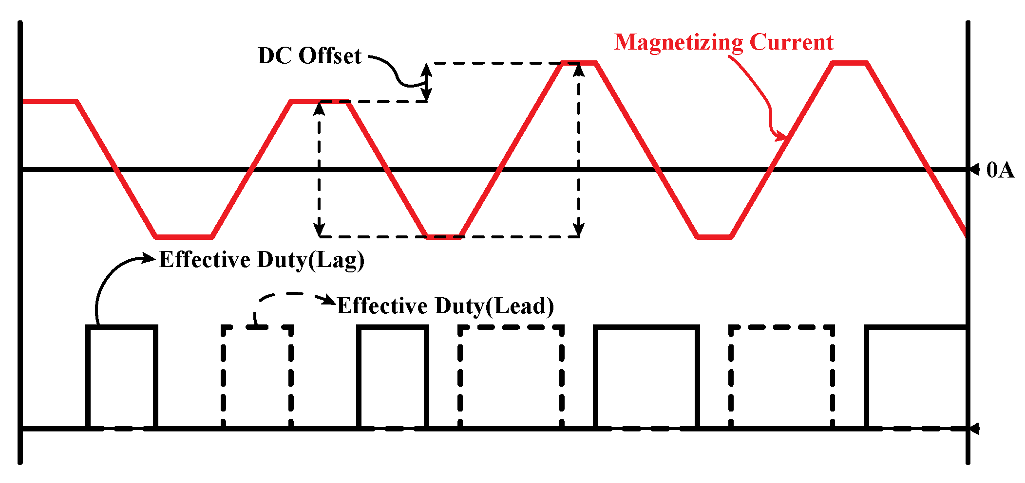
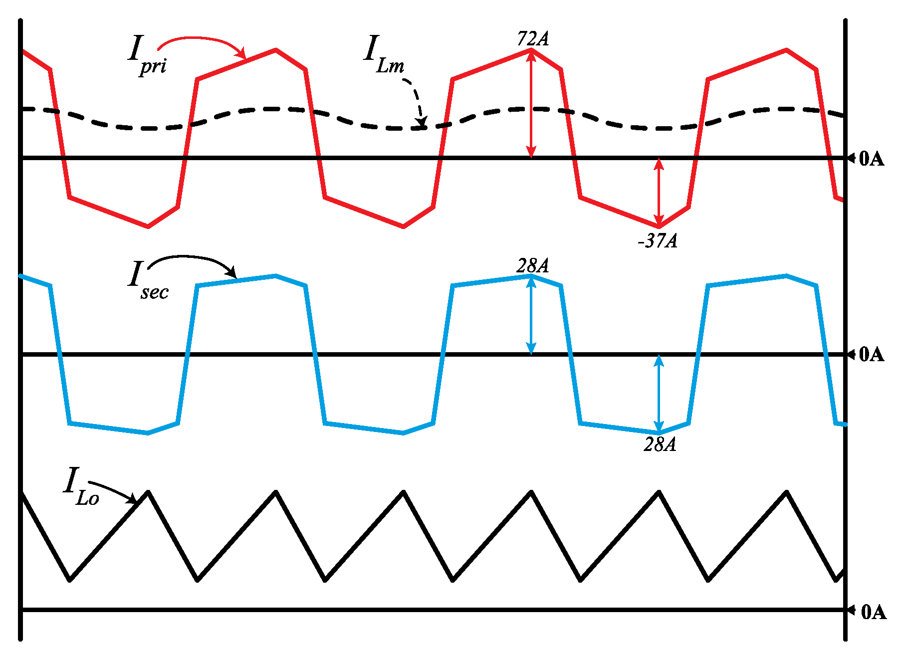
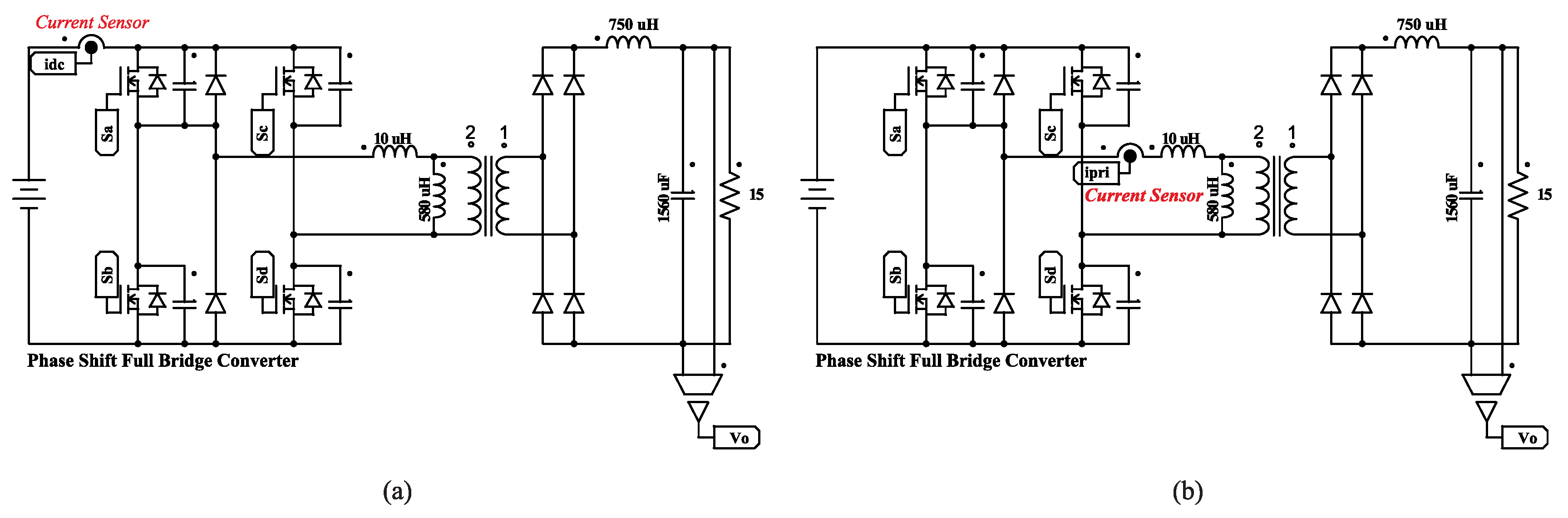
2. Primary-Side Current Imbalance of PSFB Converters

In a PSFB converter, the duty command results in a phase difference between the lagging and leading legs. The primary-side voltage of the transformer in PSFB converters is determined by the phase difference; this primary-side voltage is divided between the slew interval, which rapidly increases the primary-side current without transferring power to the secondary side, and the effective duty interval, which transfers power to the secondary side. During the slew interval, the entire primary-side voltage is applied to the leakage inductance to change the primary-side current. However, in this interval, zero voltage is applied to the magnetizing inductance, which ensures that the magnetizing current does not change. Conversely, during the effective duty interval, because most of the primary-side voltage is applied to the magnetizing inductance of the transformer, positive voltage increases the magnetizing current and negative voltage decreases the magnetizing current. Generally, in the steady state, the effective duty interval creates a volt-second balance of the magnetizing inductance, and the rising and falling values of the current must be the same. If the volt-second balance of the magnetizing inductance of the transformer is disturbed, a DC offset is generated in the magnetizing current. Figure 2 shows the magnetizing current waveform when the duty ratio fluctuates. The PSFB converter transfers energy to the secondary side from the primary side, excluding the magnetizing current components of the transformer. As shown in Figure 1, when current is detected on the secondary side, the magnetizing current DC offset on the primary side is not transferred to the secondary side, and the DC offset of the primary-side current cannot be detected. Consequently, if the output inductor current on the secondary side is detected and controlled, the magnetizing current may have a DC offset. Figure 3 shows the simulated waveform of the offset current when the secondary-side output current is detected and controlled.

3. Conventional Method for Preventing Current Imbalance

3.1. Blocking Capacitor

Adding a series of blocking capacitors to the primary side of the transformer can block the DC component of the voltage applied to the primary side, thereby preventing the volt-second imbalance from generating a current imbalance [24,25,26]. The secondary-side output current can be detected using this blocking capacitors method; hence, the generally used proportional integral current control can be easily applied for PSFB converters [15]. Furthermore, adding blocking capacitors reduce the free-wheeling current of the lagging leg of the PSFB converters, and slew interval which resulting in loss of effective duty of PSFB converters can be reduced. By these reasons, conduction losses of the PSFB converters are reduced, but complicates the ZVS of the leading leg owing to zero primary-side current at the switching instance of leading leg. Moreover, the transformer current flows through the blocking capacitor, thereby increasing the volume and cost for high-power applications.

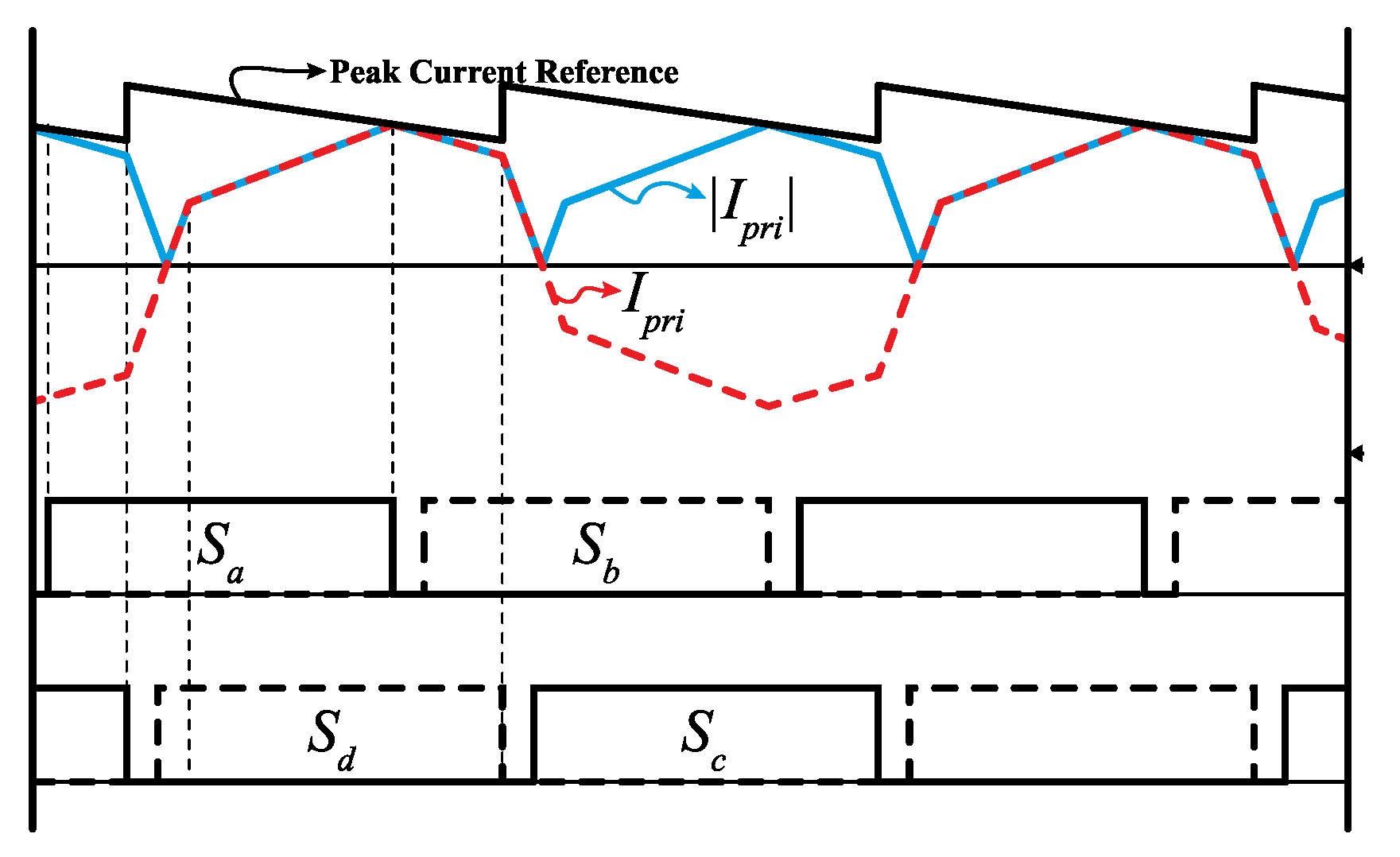
3.2. Peak Current-Mode Control with Slope Compensation

Figure 4 shows the control diagram and current detection circuit for PCMC-based PSFB converters. Figure 5 shows the corresponding gate drive signals and current waveforms. As PCMC maintains the peak current at a certain value throughout all the cycles, a current imbalance does not occur. Furthermore, the fast-response capability of the PCMC enables a higher bandwidth of the external voltage controller. However, a slope compensation technique should be integrated into the PCMC controller to prevent the sub-harmonic oscillation generated by it when the duty ratio exceeds 0.5 [18].
Figure 6 shows that the sub-harmonic oscillation is suppressed by the slope compensation method of the PSFB converters for the secondary-side inductor current detection shown in Figure 1. The gradient of the slope compensation function m a can be calculated by using the slope of the secondary inductor current in the effective duty interval m 1 and that in the freewheeling interval m 2 as shown in Equation (1). In Figure 6, the blue, dotted, and red lines represent the inductor current waveform in a steady state, inductor current when perturbation is applied, and slope compensation function, respectively. When a perturbation i o ^ is applied, the condition for the gradient of the slope compensation m a must satisfy Equation (1), which is that the perturbation current converges to 0.
m 2 m a m 1 + m a < 1
where
m 2 m 1 2 < m a , m 1 = n V i n V o L o , m 2 = V o L o .
Equation (2) is derived based on the secondary-side inductor current. In Equation (2), L o is the output inductor, V i n is the primary-side voltage, and V o is the output voltage. Equations (1) and (2) express the conditions required for the slope compensation function to suppress sub-harmonic oscillation for the secondary side. However, in PSFB converters with primary-side current detection, Equation (2) must be converted to the primary side as shown in Equations (3) and (4).
m a > 1 2 V o / n L o / n 2 V i n V o / n L o / n 2
m a > n 2 V i n + 2 n V o 2 L o .
Equations (3) and (4) define the slope compensation gradient m a required to prevent sub-harmonic oscillation under the condition of primary-side control. As expressed in Equation (4), the slope of m a is dependent on the output voltage V o . Accordingly, m a must be able to change in real time responding to a change in the input or output voltage. However, as it is difficult to change the slope in real time with digital control using a digital signal processor (DSP), the slope compensation gradient is generally fixed at the maximum value of the input and output voltages. Figure 7 shows a PSFB converter circuit with integrated PCMC slope compensation. Figure 8 shows the result of integrating slope compensation into PCMC for PSFB converter control. Although implementing slope compensation suppresses sub-harmonic oscillation, it also reduces the current-control response speed due to the slope compensation function [19].

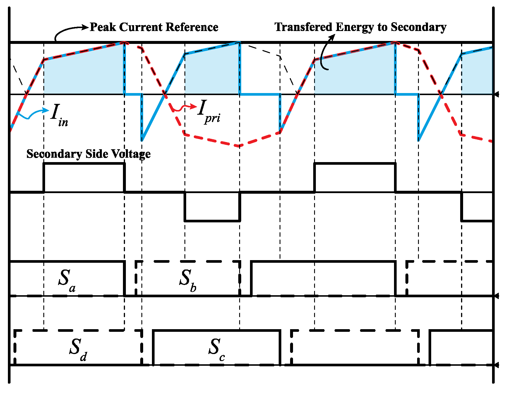
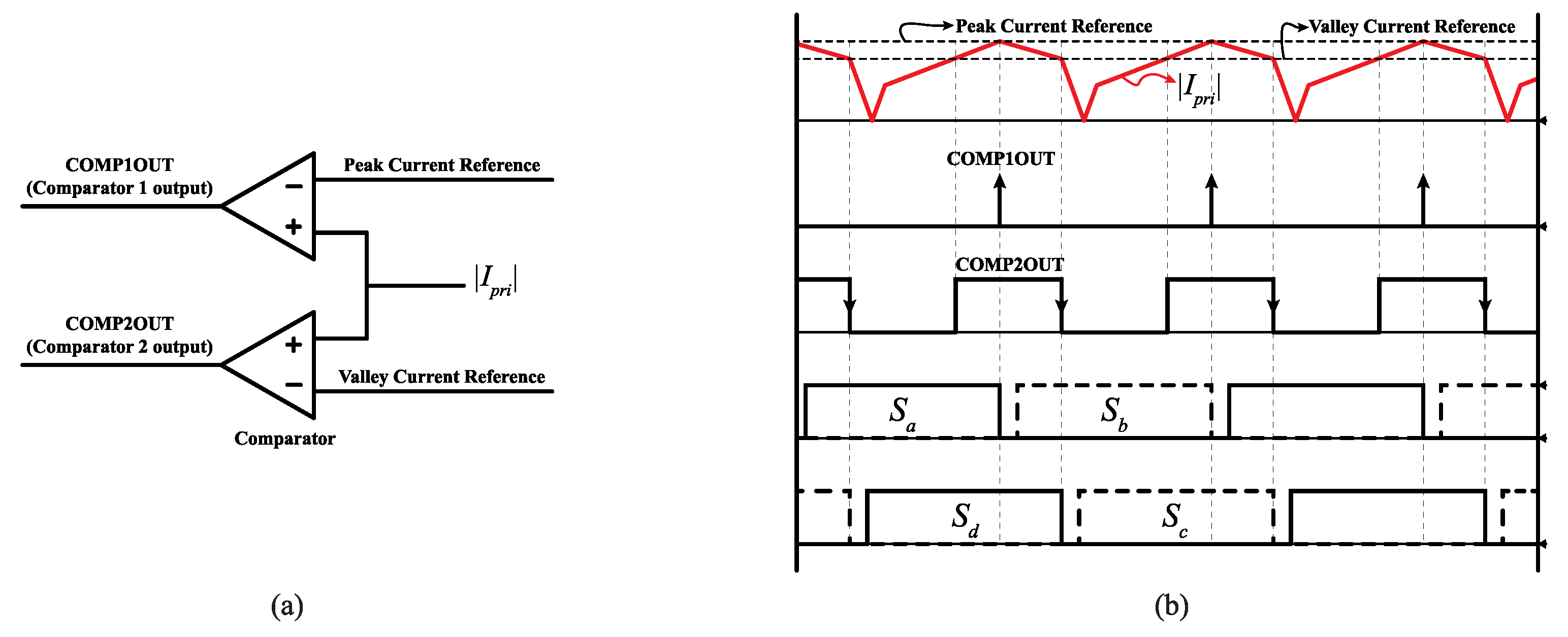
4. Proposed Hybrid Current-Mode Control of PSFB Converters

In the previous section, the causes of primary-side current imbalance in the PSFB converter were analyzed, and the published methods to prevent them were described. Adding blocking capacitors increases the cost and size of the device, and changes the ZVS conditions. Moreover, integrating a slope compensation function into PCMC reduces the response speed because of the compensation slope [19]. Considering the aforementioned conditions, control techniques that do not require additional devices and result in no response delay are required for applications with restricted space and high power, such as OBCs. In particular, the impact is significant when the charging target is a supercapacitor in which dynamic response is important. HCMC has been proposed to reduce the response delay associated with the application of slope compensation to boost converters [23]. HCMC combines PCMC and valley current-mode control. Unlike the conventional hysteresis current control method, the proposed HCMC method does not incur variations in the inductor current frequency in response to the changes in voltage because the valley current command is changed according to the operating conditions, which include the input and output voltages and switching frequency. However, for PSFB converters, as the valley current cannot be detected by the current sensor in the primary DC-link side, a new current detection method is required. In this section, the HCMC method applied to boost converter is presented, and the proposed current detection method, which applies HCMC to the PSFB converter using sensors that can detect the valley current at the primary side, is described.

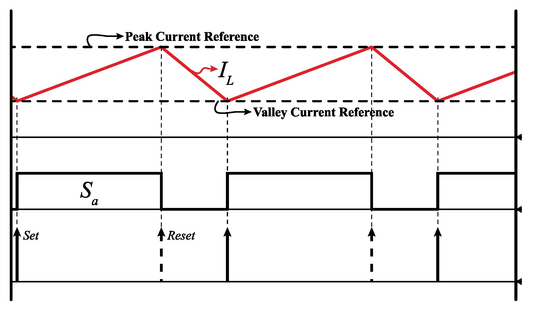
4.1. Hybrid Current-Mode Control of Boost Converter

Figure 9 shows a control block diagram of the HCMC technique proposed in Reference [23]. In this study, HCMC was applied to a non-isolated boost converter in which the peak and valley currents are easily detected. The voltage controller that generates the current command is identical to the conventional PCMC, and the peak current command is generated by adding a half of the inductor current ripple to the current command from the voltage controller. Further, the valley current command is generated by subtracting a half of the inductor current ripple from the current command from the voltage controller. If the inductor current signal increases beyond the peak current command value, the flip-flop is reset to turn off the switch S a ; alternatively, if the signal decreases below the valley current, the flip-flop is set to turn on the switch S a .
Figure 10 demonstrates the operating concept of HCMC, to illustrate the relationship between the inductor current and the signal of switch S a . Equation (5) expresses the current slopes m 1 and m 2 in the boost converter when the switch is turned on and off, respectively.
m 1 = V i n L , m 2 = V i n V o L .
Equation (6) expresses the amount of change in the current when the switch is turned on and off.
Δ I L = m 1 D T s = m 2 ( 1 D ) T s , D = V o V i n V o .
As shown in Equation (6), Δ I L can be calculated by using the rising slope m 1 and falling slope m 2 of the inductor current, and duty ratio. By substituting Equation (5) into Equation(6), Δ I L can be expressed as in Equation (7).
Δ I L = V o V i n L f s w V i n V o .
In the steady state, the difference between the peak and valley current commands must be equal to Δ I L . The current command output from the voltage controller is the mean value of the inductor current; therefore, Δ I L /2 is added to the current command to generate the peak current command. Equation (8) expresses the peak current command for HCMC. I p e a k is the peak current command and I r e f is the current command from the voltage controller. The valley current command is lower than I r e f by Δ I L / 2 ; hence, it can be expressed as Equation (9).
I p e a k = I r e f + Δ I L 2
I v a l l e y = I r e f Δ I L 2 .
As can be ascertained from the control block diagram in Figure 9, the switching of switch S a is controlled by comparing the peak and valley current commands with the inductor current. The peak and valley current commands for HCMC depend on Δ I L , which is a function of the switching frequency as in Equation (7), so that the switching frequency of the inductor current is constant, even if the input and output voltages are varied. This is not valid for the conventional hysteresis current controller with a fixed current band.

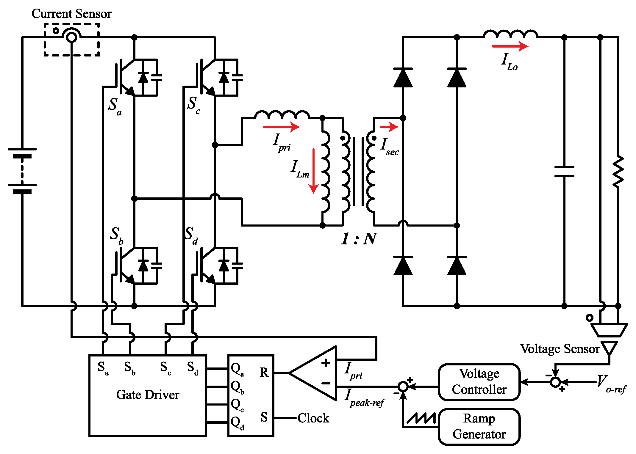
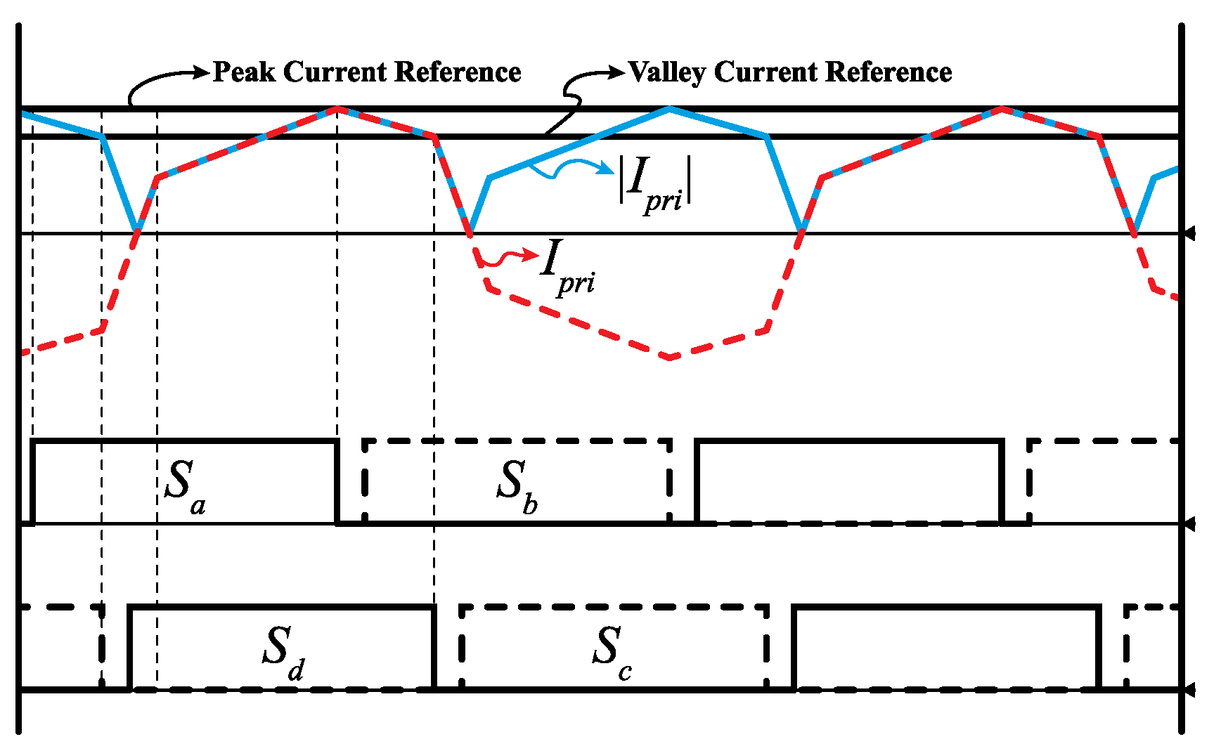
4.2. Hybrid Current-Mode Control for PSFB Converters

As explained previously, HCMC must detect the peak and valley currents. As shown in Figure 9, the peak and valley currents in conventional boost converters can be easily detected from the inductor current. Meanwhile, the current of PCMC in PSFB converters is typically detected at the primary-side DC link, as shown in Figure 7. However, this technique is difficult to apply to HCMC for PSFB due to the inability to measure the valley current in the freewheeling interval from the DC-link side. This problem can be mitigated using a method that (1) implements a current sensor on the transformer primary side to detect the alternating current, and (2) allows HCMC to be applied to the PSFB converter using an absolute-value conversion circuit to enable measuring the peak and valley currents. Figure 11 shows the PSFB converter circuit with the proposed HCMC having a primary-side alternating current detection circuit.
Figure 12a shows the circuit used to detect the absolute value of the current, and Figure 12b shows the output current waveform for the proposed method. The current sensor on the primary side of the transformer is used to detect the positive and negative currents. Furthermore, the absolute value of the primary-side current can be detected using a rectifier-amplification circuit, as shown in Figure 12. In this paper, fast recovery diode is applied in current sensing circuit to minimize the signal distortion and sensing delay. Generally, absolute current sensing circuits have sensitivity problem owing to the some parameter errors. Possible errors from the absolute sensing circuit of primary side current are caused by resistor parameter, current sensors, and diode forward voltage. The resistor parameter and current sensor errors can make voltage gain error of small nonlinearity on the detected absolute current value, but thus gain error or small nonlinearity make no trouble in the hybrid mode current control. Diode forward voltage drop also can makes sensing errors but this voltage drop can be easily compensated by adding offset value.
Figure 13 illustrates the conceptual waveforms of several current and gate signals corresponding to the proposed HCMC-based PSFB converter. In the waveforms, I P R I is the primary-side current, and | I P R I | is the absolute signal of the primary-side current from the absolute-value detection circuit. I p e a k and I v a l l e y represent the peak and valley current commands, respectively. When the primary-side current | I P R I | reaches I p e a k , the flip-flop in Figure 11 is reset by a comparator, which then turns off the S a and turns on the S b switches. Thus, the voltage applied to the primary side of the transformer becomes 0, and the magnetizing and output inductors are freewheeled. When the primary-side current value is reduced to the valley current value owing to this freewheeling, the flip-flop shown in Figure 11 is set, which turns off switch S d and turns on S c . Thereafter, + V d c is applied to the primary side of the transformer.
In the proposed system, peak and valley current controls are realized by utilizing the absolute value of the primary-side current as illustrated in Figure 13. However, as the primary-side current—rather than the current—must be controlled for appropriate PSFB converter operation, the peak current command must be generated by converting the maximum value of the secondary-side output inductor current to a value suitable for the primary side. Moreover, the valley current command must consider the minimum value of the output inductor current and the duty loss caused by the slew interval.
Figure 14 elaborates the steady-state current waveforms of the PSFB converter. The current waveforms consist of positive and negative half-cycles. The positive and negative half-cycles of the primary-side current are symmetrical, and hence, only the positive current interval is described here. In this figure, t o denotes the interval during which a positive voltage is applied to the primary side of the PSFB converter transformer, and t 2 denotes the interval during which 0 V is applied to the primary side of the transformer owing to phase shifting.
Accordingly, t 0 t 2 is the interval corresponding to the overall duty ratio D applied to the converter by the controller, and t 2 t 3 is the freewheeling interval corresponding to the duty ratio D . However, in the slew interval in which the primary-side current is changed to positive from negative that is, t 0 t 1 in Figure 14, the primary-side voltage is applied to the leakage inductor; hence, 0 V is applied to the magnetizing inductor. A duty loss occurs in this interval; hence, this interval has been defined as the ineffective duty ratio interval Δ D . Herein, the method to generate the peak and valley current commands required to drive the HCMC for the PSFB converter is described.
Figure 14 shows the waveforms for the magnetizing current and transferred output current. Therefore, the magnetizing current must be considered in determining the peak current command. Equation (10) expresses the relationship among the primary-side current, magnetizing current, and secondary-side output inductor current.
i P R I = i L o + i L m , i L o = n i L o ,
where i L o is the output inductor current and i L o is the primary-side converted output inductor current. In addition, i L m is the magnetizing current of the transformer, and i P R I is the primary-side current of the transformer. The amplitude of the magnetizing current I M can be calculated by quantifying the relationship between the magnetizing current and the applied voltage, as follows:
V i n = L m d i L m d t = L m d i L m D e f f T s = 2 I M L M D d f f T s ,
where L m is the magnetizing inductance, T s is the switching cycle, and D e f f is the effective duty ratio required to transfer power to the secondary side, which can be expressed by Equation (12).
D e f f = V o n V i n .
The maximum values of the magnetizing current can be calculated by substituting Equation (12) into Equation (11), as follows:
I M = V o 2 n L m f s w ,
where f s w is the switching frequency. As shown in Figure 14, the peak current command I p e a k , which is the primary-side current at t 2 , can be calculated as follows:
I p e a k = I M + I L o m a x ,
where I L o m a x is the current obtained by converting the secondary-side maximum load current value to the primary side.
The primary-side valley current command is now calculated from the load current. The valley current command I v a l l e y of the PSFB converter must be equal to the primary-side current I p 2 at t 2 as shown in Figure 14.
I v a l l e y = I p 2 .
During the freewheeling interval, the voltage applied to the magnetizing inductor is 0; therefore, the magnetizing current is maintained at I M . Accordingly, during the freewheeling period 1 D , the secondary-side current decreases in proportion to the output voltage. Thus, the minimum current on the primary side, I p 2 , can be expressed as follows:
I p 2 = n I L o m a x V o L o 1 D T s + I M ,
where I L o m a x is the maximum current of the secondary-side inductor, which can be expressed as
I L o m a x = I L o + Δ I L o 2 ,
where I L o is the average value of the secondary-side current, and Δ I L o is the fluctuation of the secondary-side current.
On the other hand, the valley current command, I v a l l e y , can be derived from the peak current command using Equations (14) and (16), as follows:
I v a l l e y = I p e a k n V o L o ( 1 D ) T s ,
where L o represents the secondary-side output inductor. Equation (18) must be solved to generate the valley current command of the PSFB converter. Consequently, the overall duty ratio D of the PSFB converter applied by the controller must be calculated. The overall duty ratio is the sum of the effective and ineffective duty ratios; hence, it can be expressed as
D = D e f f + Δ D ,
where Δ D is the ineffective duty ratio interval corresponding to t 0 t 1 in Figure 14. The entire input voltage is applied to the leakage inductor L l k during the period of Δ D T s , and hence, the equation for the leakage inductor voltage can be used to calculate Δ D .
V i n = L l k d i p r i d t = L l k I p 1 + I p 2 Δ D T s .
Here, I p 1 for the primary side can be calculated using the secondary-side current, as follows:
I p 1 = n I L o m i n n I M ,
where I M is the amplitude of the magnetizing current. As the magnetizing current is negative at t 1 , it is subtracted from the secondary-side inductor current. I L o m i n is the minimum secondary-side current value and can be defined as in Equation (22).
I L o m i n = I L o Δ I L o 2 .
From Equations (16), (17), (21) and (23), I p 1 + I p 2 can be obtained as Equation (23). Δ D can be obtained as Equation (24) using Equations (20) and (23).
I p 1 + I p 2 = n 2 I L o V o L o ( 1 D ) T s
Δ D = n L l k V i n 2 I L o f s w V o L o ( 1 D ) .
By substituting Equations (12) and (24) into Equation (19), D can be obtained as in Equation (25).
D = V o n + 2 n L l k L L o f s w n L l k V o L o V i n n L l k V o L o .
Equation (25) shows the overall duty ratio for a PSFB converter cycle. Finally, the valley current command that can compensate for each cycle of the ineffective duty ratio interval is determined using Equations (18) and (25).

5. Simulation and Digital Code Initialization for Experiment

5.1. Simulation Result

In this section, the operation of the proposed PSFB converter is simulated to compare the results of the proposed HCMC- and conventional PCMC- based PSFB converters. Table 1 lists the simulation and experimental circuit parameters. The input voltage is 45 V, the output voltage is 50 V, and the transformer turns ratio is set to 2. Under the condition expressed by Equation (4), 44,000 A/s was used as the gradient of the slope compensation function for PCMC. The simulation was conducted using Powersim software. Figure 15 shows the PSIM simulation circuit, and HCMC and PCMC were implemented by a digital control code using C-block.
Figure 16 shows the simulated waveforms for steady-state operation under the conditions of output voltage commands of 40 V and 50 V for the proposed HCMC-based PSFB converter. Figure 16a,c and b,d show the simulated results for the output voltages of 40 V and 50 V, respectively. Figure 16c,d show enlarged views of the detected current waveforms. V o is the output voltage, and I P R I is the primary-side current. I s e n s o r is the simulated waveform for the current sensor side. As with the experimental circuit, the output voltage of the current sensor was 1/6th the primary-side current. When the primary-side current was set to 20 A, the current sensor output I s e n s o r was 3.3 V, Additionally, changing the output voltage command resulted in a change in the peak and valley current commands. Even if the peak and valley currents vary according to the output voltages, the simulation results show that a constant frequency was maintained for the proposed HCMC method. Furthermore, the simulation results show that the sub-harmonic oscillation phenomenon was not generated despite a large duty ratio. Figure 17 shows the simulated output voltage waveforms for the HCMC- and PCMC-based PSFB converters. Generally, if slope compensation is applied to PCMC, the primary current cannot reach the current command value at the next pulse-width modulation (PWM) cycle. Hence, the PCMC control with slope compensation results in a response delay. However, the proposed HCMC demonstrated no response delay, because it does not require slope compensation.

5.2. Digital Code Initialization for Experiment

This subsection describes the method for implementing HCMC using a DSP. A comparator that detects peak and valley currents is necessary to implement the proposed current-mode control technique.
Figure 18 illustrates a hardware structure and operating timing diagram. Two comparators are required to implement the peak and valley current-mode controls. Both comparators are directly connected to the current sensor output. The key operation is to detect the rising edge of the peak current detection comparator and the falling edge of the valley current detection comparator.
When the primary-side current reaches the peak current reference value, the peak current comparator output is high. Subsequently, the digital controller catches the rising edge and changes the state of the leading leg switch. A leading-edge blanking of 500 ns has been applied to filter the sensing noise. Conversely, when the primary-side current reaches the valley current reference value, the digital control detects the falling edge of the valley current comparator output, thereby changing the state of the lagging leg switch.

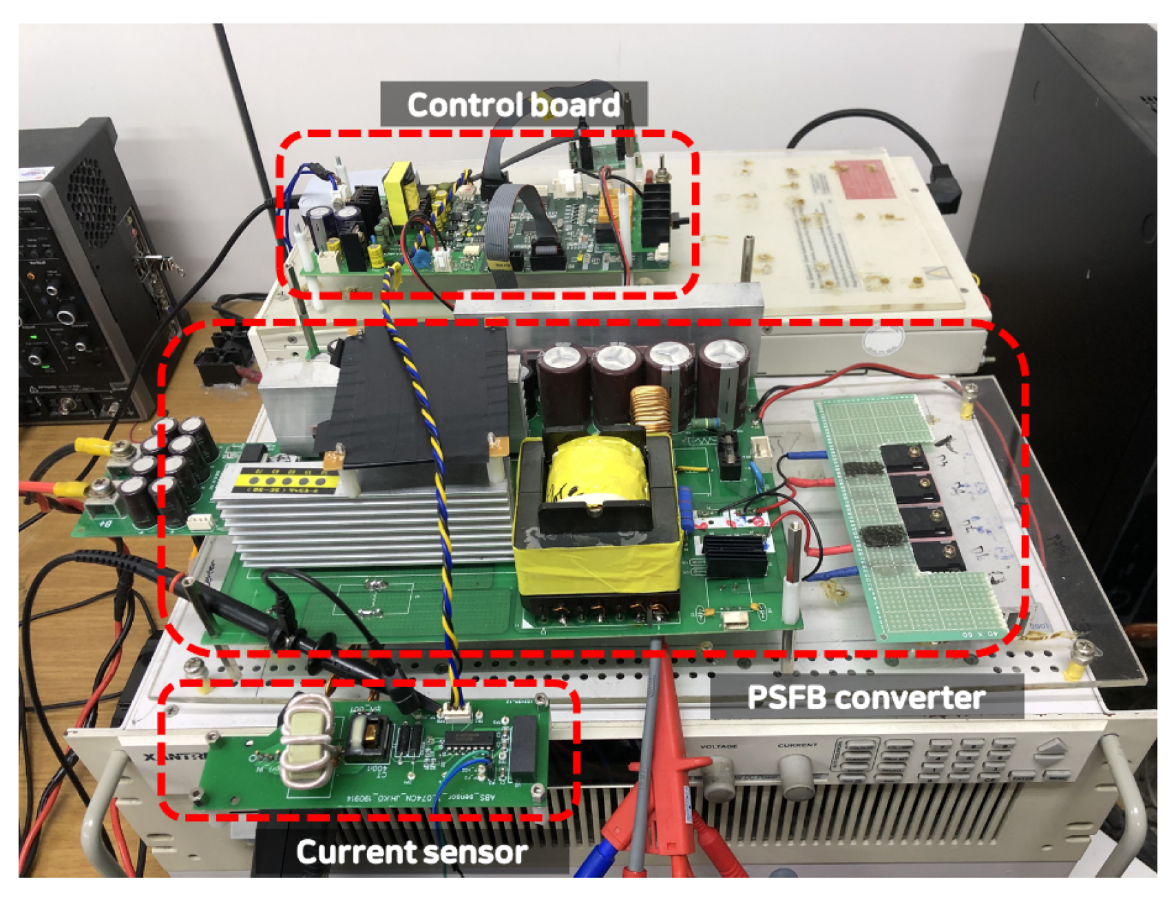
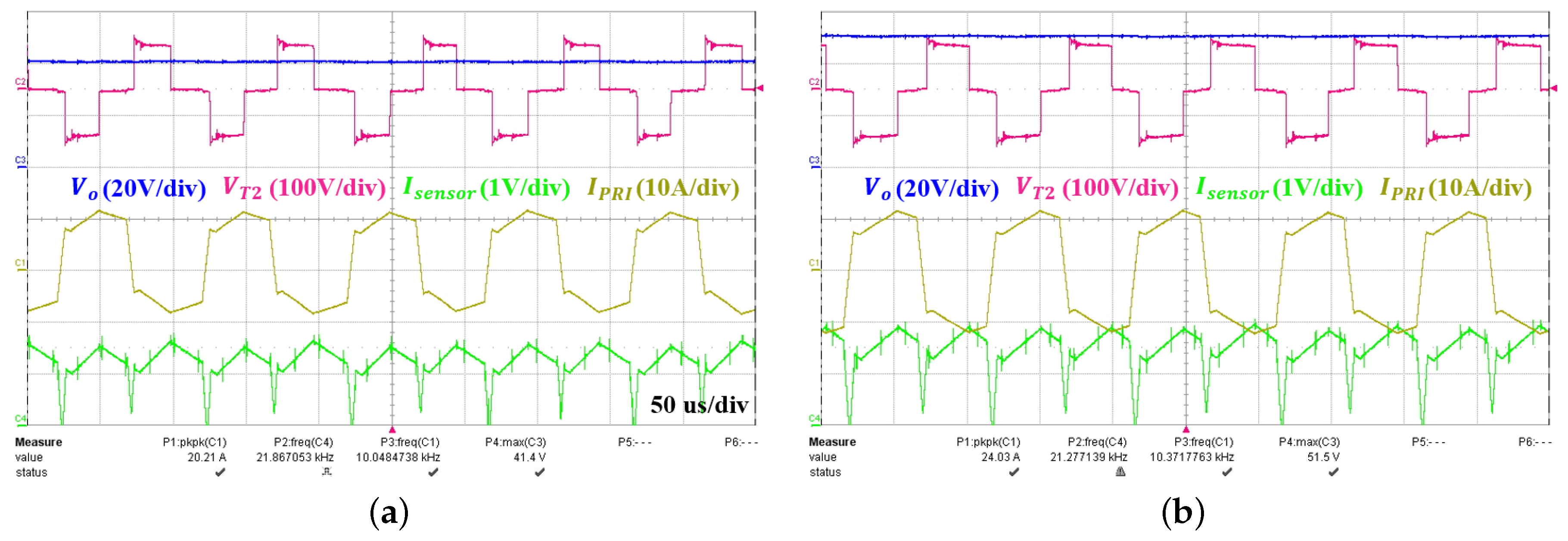
5.3. Experiment Results

Figure 19 shows the experimental setup for the proposed HCMC-based PSFB converter. It consists of a PSFB power board, control board, and sensor that detects the absolute value of the transformer primary current. The experimental parameter values are identical to those employed in the simulations (Table 1). A TMS320F28035 was employed as the control unit.
Figure 20a shows the experimental voltage and current waveforms at an output voltage of 40 V. In this figure, V T 2 is the transformer secondary-side voltage, I P R I is the primary-side current, and I s e n s o r is the current sensor output voltage. As shown in Figure 20a, an output voltage of 40 V corresponds to a transformer secondary-side voltage of 90 V, which varies according to the designed turns ratio. Figure 20b shows the experimental voltage and current waveforms for the proposed HCMC method at an output voltage of 50 V. As was observed in the corresponding simulated result in Figure 16, the peak and valley current commands of the controller vary according to the output voltage command to generate the correct duty cycle.
Figure 21a shows an enlarged waveform of the current sensor output shown in Figure 20a. To filtering a sensing noise, 500 ns Leading Edge Blanking (LEB) time has been applied. By LEB, spikes on current sensor waveform does not affect to control and converter circuit. In the steady state, the switching frequency is maintained at 20 kHz, and the switch is accurately set and reset according to the peak and valley current commands of the controller. In Figure 21b, the sub-harmonic oscillation phenomenon is not generated even when the duty cycle exceeds 0.5. As observed in the simulation and experimental results, the proposed HCMC method allows the peak and valley current commands to change, even if the output voltage fluctuates, thereby demonstrating that the switching frequency does not change. Furthermore, the experimental results indicate that the sub-harmonic oscillation phenomenon is not generated despite a large duty ratio. Figure 22 shows the response speeds of the PSFB converters with the proposed HCMC and conventional slope-compensated PCMC techniques. As was observed from the simulated results in Figure 16, a faster response speed was achieved when the proposed HCMC was applied.

6. Conclusions

A PSFB converter with HCMC was proposed in this paper to prevent current imbalance and compensate for an ineffective duty ratio. With PSFB converters, implementing double-loop voltage control using secondary-side current detection may generate a current imbalance that results in transformer saturation. Furthermore, although applying PCMC to a PSFB converter can prevent primary-side current imbalance, a duty ratio above 0.5 results in sub-harmonic oscillation. The slope compensation technique can be used to address this problem. However, as the slope compensation gradient is proportional to the output voltage, it must be varied according to the output. As it is difficult to vary the slope of the slope compensation function in real time, the maximum gradient value is typically applied, which leads to a response delay. Therefore, an HCMC method that addresses the problems of response delay and primary-side current imbalance of the PSFB converter was presented in this paper. To apply the proposed HCMC method to PSFB converters, an absolute-value sensor circuit for the primary-side current was proposed and evaluated. The experimental results demonstrated that faster response times could be obtained by applying HCMC instead of PCMC, as the former does not require slope compensation. Furthermore, the peak and valley current commands varied according to the output voltage, which enabled control without frequency fluctuation. In summary, a PSFB converter with HCMC was developed to prevent current imbalance and compensate for the ineffective duty ratio, and its performance was verified through simulations and experiments.

Author Contributions

J.-H.K. implemented the system and performed the experiments. H.-W.K. and J.-M.K. conceived the idea and wrote the paper. S.-W.B. analyzed the proposed method. K.-M.L. and K.-Y.C. assisted in idea development and paper writing. All authors have read and agreed to the published version of the manuscript.

Funding

This work was supported by the “Human Resources Program in Energy Technology” of the Korea Institute of Energy Technology Evaluation and Planning (KETEP), granted financial resource from the Ministry of Trade, Industry and Energy, Republic of Korea. (No. 20184030202270). This work was supported by the Korea Agency for Infrastructure Technology Advancement (KAIA) grant funded by the Ministry of Land, Infrastructure and Transport (Grant No. 20QPWO-B152221-02).

Conflicts of Interest

The authors declare no conflict of interest.

References

  1. Khaligh, A.; Dusmez, S. Comprehensive topological analysis of conductive and inductive charging solutions for plug-in electric vehicles. IEEE Trans. Veh. Technol. 2012, 61, 3475–3489. [Google Scholar] [CrossRef]
  2. Yong, J.Y.; Ramachandaramurthy, V.K.; Tan, K.M.; Mithulananthan, N. A review on the state-of-the-art technologies of electric vehicle, its impacts and prospects. Renew. Sustain. Energy Rev. 2015, 49, 365–385. [Google Scholar] [CrossRef]
  3. Fahem, K.; Chariag, D.E.; Sbita, L. On-board bidirectional battery chargers topologies for plug-in hybrid electric vehicles. In Proceedings of the International Conference on Green Energy Conversion Systems (GECS), Hammamet, Tunisia, 23–25 March 2017; pp. 1–6. [Google Scholar]
  4. Grenier, M.; Aghdam, M.G.H.; Thiringer, T. Design of on-board charger for plug-in hybrid electric vehicle. In Proceedings of the 5th IET International Conference on Power Electronics, Machines and Drives, Brighton, UK, 19–21 April 2010; pp. 1–6. [Google Scholar]
  5. Haghbin, S.; Khan, K.; Lundmark, S.; Alakula, M.; Carlson, O.; Leksell, M.; Wallmark, O. Integrated chargers for EV’s and PHEV’s: Examples and new solutions. In Proceedings of the XIX International Conference on Electrical Machines, Rome, Italy, 6–8 September 2010; pp. 1–6. [Google Scholar]
  6. Haghbin, S.; Lundmark, S.; Alakula, M.; Carlson, O. Grid-connected integrated battery chargers in vehicle applications: Review and new solution. IEEE Trans. Ind. Electron. 2013, 40, 459–473. [Google Scholar] [CrossRef]
  7. Yilmaz, M.; Krein, P.T. Review of battery charger topologies, charging power levels, and infrastructure for plug-in electric and hybrid vehicles. IEEE Trans. Power Electron. 2013, 28, 2151–2169. [Google Scholar] [CrossRef]
  8. Lee, M.; Kim, C.L.K.; Park, M.; Moon, G. A phase-shift full-bridge converter with novel voltage oscillation clamping circuit for electric vehicle on-board charger. In Proceedings of the 10th International Conference on Power Electronics and ECCE Asia, Busan, Korea, 27–30 May 2019; pp. 2040–2045. [Google Scholar]
  9. Cha, H.; Chen, L.; Ding, R.; Tang, Q.; Peng, F.Z. An alternative energy recovery clamp circuit for full-bridge PWM converters with wide ranges of input voltage. IEEE Trans. Power Electron. 2008, 23, 2828–2837. [Google Scholar]
  10. Hsieh, Y.; Huang, C. Li-ion battery charger based on digitally controlled phase-shifted full-bridge converter. IET Power Electron. 2011, 4, 242–247. [Google Scholar] [CrossRef]
  11. Wang, H.; Shang, M.; Khaligh, A. A PSFB-based integrated PEV onboard charger with extended ZVS range and zero duty cycle loss. IEEE Trans. Ind. Appl. 2017, 53, 585–595. [Google Scholar] [CrossRef]
  12. Vlatkovic, V.; Sabate, J.A.; Ridley, R.B.; Lee, F.C.; Cho, B.H. Small-signal analysis of the phase-shifted PWM converter. IEEE Trans. Power Electron. 1992, 7, 128–135. [Google Scholar] [CrossRef]
  13. Claassens, J.A.; Hofsajer, I.W. A flux balancer for phase shift ZVS DC-DC converters under transient conditions. In Proceedings of the Twenty-First Annual IEEE Applied Power Electronics Conference and Exposition, Dallas, TX, USA, 19–23 March 2006; pp. 523–527. [Google Scholar]
  14. Panov, Y.; Jovanovi, M.M.; Yueyong, L.G.M. Transformer-flux-balancing control in isolated bidirectional DC-DC converters. In Proceedings of the IEEE Applied Power Electronics Conference and Exposition (APEC 2014), Fort Worth, TX, USA, 16–20 March 2014; pp. 49–56. [Google Scholar]
  15. Kutkut, N.H.; Luckjiff, G. Current mode control of a full bridge DC-to-DC converter with a two inductor rectifier. In Proceedings of the 28th Annual IEEE Power Electronics Specialists Conference, Saint Louis, MO, USA, 22–27 June 1997; pp. 203–209. [Google Scholar]
  16. Kim, T.; Lee, S.; Choi, W. Design and control of the phase shift full bridge converter for the on-board battery charger of the electric forklift. In Proceedings of the 8th International Conference on Power Electronics—ECCE Asia, Jeju, Korea, 30 May–3 June 2011; pp. 2709–2716. [Google Scholar]
  17. Jeong, C.-Y. Improved phase-shift pulse-width modulation full-bridge converter using a blocking capacitor. J. KIIEE 2011, 25, 20–29. [Google Scholar]
  18. Taeed, F.; Nymand, M. Adaptive slope compensation for high bandwidth digital current mode controller. In Proceedings of the 2015 IEEE 11th International Conference on Power Electronics and Drive Systems, Sydney, Australia, 9–12 June 2015; pp. 604–608. [Google Scholar]
  19. Sun, Y.; Jiao, B. Design of a soft-switched phase-shift full bridge converter. In Proceedings of the 2016 3rd International Conference on Systems and Informatics (ICSAI), Shanghai, China, 19–21 November 2016; pp. 230–234. [Google Scholar]
  20. Kondrath, N.; Kazimierczuk, M.K. Slope compensation and relative stability of peak current-mode controlled PWM dc-dc converters in CCM. In Proceedings of the 2013 IEEE 56th International Midwest Symposium on Circuits and Systems (MWSCAS), Columbus, OH, USA, 4–7 August 2013; pp. 477–480. [Google Scholar]
  21. Chen, J.; Hwang, Y.; Liou, J.; Ku, Y.; Yu, C. A new buck converter with optimum-damping and dynamic-slope compensation techniques. IEEE Trans. Ind. Electron. 2017, 64, 2373–2381. [Google Scholar] [CrossRef]
  22. Kim, M. High-performance current-mode-controller design of buck LED driver with slope compensation. IEEE Trans. Ind. Electron. 2018, 33, 641–649. [Google Scholar] [CrossRef]
  23. Oh, S.-M.; Ko, J.-H.; Kim, H.-W.; Cho, K.-Y. A Hybrid Current Mode Controller with Fast Response Characteristics for Super Capacitor Applications. Electronics 2019, 8, 112. [Google Scholar] [CrossRef] [Green Version]
  24. Cho, J.G.; Cho, G.H. Novel off-line zero-voltage switching PWM ac/dc converter for direct conversion from ac line to 48 VDC bus with power factor correction. In Proceedings of the IEEE Power Electronics Specialist Conference—PESC, Seattle, WA, USA, 20–24 June 1993; pp. 689–695. [Google Scholar]
  25. Cho, J.G.; Sabate, J.; Lee, F.C. Novel zero-voltage transition PWM dc/dc converter for high power applications. In Proceedings of the 1994 IEEE Applied Power Electronics Conference and Exposition—ASPEC, Orlando, FL, USA, 13–17 February 1994; pp. 143–149. [Google Scholar]
  26. Cho, J.G.; Sabate, J.A.; Hua, G.; Lee, F.C. Zero voltage and zero current switching full bridge PWM converter for high power applications. In Proceedings of the 1994 Power Electronics Specialist Conference—PESC, Taipei, Taiwan, 20–25 June 1994; pp. 102–108. [Google Scholar]
Figure 1. Secondary-side current detection of phase-shifted full-bridge (PSFB) converters.
Electronics 09 01395 g001
Figure 2. Magnetizing current imbalance by duty ratio fluctuation.
Electronics 09 01395 g002
Figure 3. Current waveforms under the magnetization current imbalance.
Electronics 09 01395 g003
Figure 4. Circuit diagram of peak current-mode control (PCMC)-based PSFB converters.
Electronics 09 01395 g004
Figure 5. Sub-harmonic oscillation in the primary-side current of PCMC-based PSFB converters when the duty ratio exceeds 0.5.
Electronics 09 01395 g005
Figure 6. Slope compensation on the secondary-side inductor current to suppress sub-harmonic oscillation.
Electronics 09 01395 g006
Figure 7. Circuit diagram of PCMC with slope compensation for PSFB converters.
Electronics 09 01395 g007
Figure 8. Primary-side current waveform with slope compensation for PCMC-based PSFB converters.
Electronics 09 01395 g008
Figure 9. Control block diagram of hybrid current-mode boost converter.
Electronics 09 01395 g009
Figure 10. Operation principle of HCMC.
Electronics 09 01395 g010
Figure 11. Circuit diagram of the proposed hybrid current-mode control (HCMC) for PSFB converters.
Electronics 09 01395 g011
Figure 12. Absolute-value detection method; (a) Circuit diagram, (b) Output waveform.
Electronics 09 01395 g012
Figure 13. Primary-side current waveforms with the proposed HCMC for PSFB converters.
Electronics 09 01395 g013
Figure 14. Steady-state current waveforms of the PSFB converters.
Electronics 09 01395 g014
Figure 15. Simulation circuit of PSFB converters using Powersim: (a) PCMC circuit; (b) HCMC circuit.
Electronics 09 01395 g015
Figure 16. Simulated current waveforms of the proposed HCMC according to output voltages: (a) V o = 40 V; (b) V o = 50 V; (c) Enlarged (a); (d) Enlarged (b).
Electronics 09 01395 g016
Figure 17. Simulation results of the voltage response of the proposed HCMC and conventional PCMC.
Electronics 09 01395 g017
Figure 18. Hardware structure and operating principle of the digital controller; (a) Circuit diagram of the comparator, (b) Trip zone interrupt timing of the proposed HCMC.
Electronics 09 01395 g018
Figure 19. Experimental circuit configuration.
Electronics 09 01395 g019
Figure 20. Experimental current and voltage waveforms of the proposed HCMC: (a) V o = 40 V; (b) V o = 50 V; ( V o = 20 V/div, V T 2 = 100 V/div, I s e n s o r = 1 V/div, I P R I = 10 A/div).
Electronics 09 01395 g020
Figure 21. Experimental current and voltage waveforms of the proposed HCMC: (a) V o = 40 V; (b) V o = 50 V; ( V o = 20 V/div, I s e n s o r = 500 mV/div).
Electronics 09 01395 g021
Figure 22. Experimental results of the voltage response of the proposed HCMC and conventional PCMC techniques (5 V/div, 100 ms/div).
Electronics 09 01395 g022
Table 1. Simulation using Powersim.
ParameterValueUnit
Input Voltage45V
Output Voltage50V
Leakage inductance20uH
Magnetizing inductance580uH
Output inductor750uH
Load resister10Ω
Switching frequency20kHz
Max slope44,000A/s
Turns ratio2-

