Effect of the Ions on the Electron Collision Operator through Electronic Trajectory Modification
by
Yasmina Ben Nana
1, 
Fethi Khelfaoui
1,2,
Said Douis
1,2,
Eshrat Sadeghzadeh Lari
3 and
Mohammed Tayeb Meftah
1,2,* 1
Laboratoire de Recherche de Physique des Plasmas et Surfaces (LRPPS), UKMO, Ouargla 30000, Algerie
2
Département de Physique, Faculté de Mathématiques et Sciences de la matière, Université Kasdi-Merbah, Ouargla 30000, Algerie
3
Department of Physics, Faculty of Science, Vali-e-Asr University of Rafsanjan, Rafsanjan 7718897111, Iran
*
Author to whom correspondence should be addressed.
Atoms 2019, 7(3), 77; https://doi.org/10.3390/atoms7030077
Submission received: 14 June 2019
/
Revised: 12 August 2019
/
Accepted: 14 August 2019
/
Published: 16 August 2019
(This article belongs to the Special Issue Plasma Spectroscopy in the Presence of Magnetic Fields)
Abstract
:We investigate the ion effect on the broadening of the spectral line profile by the free electrons collisions with the emitters in plasmas. We only considered the weak collisions’ contribution. This effect has a consequence on the trajectories of the free electrons through the electric microfield created by the ions of the plasma. Thanks to the Meijer’s functions, the calculation of the electronic Stark broadening is precisely established.
1. Introduction
One source of the broadening of the line profiles in plasmas results from the collisions among emitters (neutral atoms or ions) and the other particles of the plasma. The line shape analysis relies on measurable macroscopic plasma parameters such as inventory of chemical species and their temperatures and number densities. In this paper, the term collisions refer to the interactions between the plasma constituents or particles (neutrals and charged particles). This means that the broadening of the line profile is caused by the various types of interactions between emitting atoms and perturbers (electrons or ions of the plasma). As is known, the Stark line broadening results from the contributions of both the plasma electrons and ions through their interactions with the emitter. Using an old theory, the ion contribution to Stark broadening was widely investigated for lines emitted by hydrogen, hydrogen-like ions and helium neutrals [1,2,3,4,5,6]. The commolyn used approximation in this investigation is the classical path approximation for electrons [1,3]. Other often used approximations in plasma emission spectroscopy are the impact approximation for the treatment of the emitter–electron interactions and the quasi-static approximation for that the emitter–ion interactions [1]. These approximations are useful to establish the influence of these particles on the emitted line profile in the plasmas. Following this description, the quasi-static approximation and the impact approximation are separately treated to have the spectral line profiles. However, bhow would the line profile be affected if we considered the colliding electron with the emitting atom as moving under the influence of the ion electric microfield? This microfield prevents the free colliding electron from following a straight trajectory. Another approximation we need in our paper is the semi-classical dipolar electric one [7,8]. It is an acceptable approximation because it shows a good agreement compared to numerous experiments [9,10]. In this work, we deal with helium plasma by considering three approximations: impact approximation for the electrons, quasi-static approximation for the ions and the electric dipolar approximation. The contribution of our investigation is the dependency of the collision operator on the ion microfield. We notice here that Djurović et al [11] used the effects of the microfield distribution on collision operator. Thus, our work starts by giving the principal theoretical elements of the spectral line profile in Section 2. Section 3 is devoted to give our theoretical investigation to derive the collision operator. The conclusion is presented in Section 4.
2. Spectral Line Theory
The foundations of the spectral line shape theory can be found in the works of Baranger, Griem and collaborators [1,2,3,4,5,6,7,12,13] as well as more recently in the work of Kogan, Lisitsa and collaborators [8]. Using the experimental results in [9,10,14], theoretical improvements, including the ions dynamics [5,15] and the electron broadening [7,16,17], were accomplished. In the present paper, we focus on the theory of the line broadening caused by the electron collisions in the impact regime. During the collision between the free electron and the emitter, we consider the effect of the static ion electric microfield on the electron trajectory. Thus, the spectral line profile is given by the following expression
where F is the time-averaged intensity of the electric microfield created by the ions of the system. F is considered obeying to the microfield distribution [18,19,20]. are the upper states and are the lower states involved in the transition under consideration. is the collision operator depending on the ions electric microfield F, as shown in next section. In our work, we consider only the broadening of the line profile caused by the collision of the free electrons with the atomic emitters. For simplicity, natural line broadening as well as Doppler and ionic Stark broadenings are ignored in this work. If the plasma is quasi-fully-ionized, the free electrons must be sensitive to the electric microfield created by the ions. Their trajectories are not straight lines and are given approximatively by
such that is the electric microfield created by the ions of the plasma (we neglect others sources of force acting on the free electron), whereas m is the electron mass. are are the initial conditions, which are, respectively, the impact parameter and the velocity of the free electron. Below, we show that the maximum value of is the radius of the Debye sphere.
3. Electron Collision Operator
To have the broadening formula of the line profile by the electron collisions, we have considered that the effect of the electric field resulting from the free electrons has no effect on the colliding electron trajectory. This assumption is related to the fact that the electrons are very light and then moving with high velocities giving a very fluctuating electric field. Thus, we have considered only the effect of the electric field created by the ions on the collision between the colliding electron and an emitting atom.
Now, we write the expression that gives the broadening [2] corresponding to a state “a” (the sub-states are , “a” is the upper state of the studied transition from the lower state “b” with sub-states for example)
where is the well known Maxwell probability density of the velocity
and [2]
where S is S-matrix and R is the position operator of the bounded electron of the helium atom and the subscript ( is its standard component) and is the electric field created by the colliding electron at time u on the emitting atom given by the following expression (expressed in CGS units)
Using Equation (6) and the substitution
Equation (5) becomes
When we carry out the average on the impact parameter and the velocity V of the electron, the last formula gives the effect of the colliding electrons on the broadening of the line profile emitted by the plasma.
To make Equation (8) easy to use, we have the next expansion
and we use the fact that the scattered electron is subjected to a force not very different from , which is itself equal to the electric force (m is the electron mass). Therefore, the real part of Equation (8) (responsible to the broadening by the electron collision) is given by
The last equation can be transformed to
where
Performing the average of Equation (14) over the impact parameter and the velocity V by using the Maxwell probability density, we get the diagonal matrix element of the collision operator as the following
where (by using Equations (3), (4) and (15)–(18))
such that are defined in Equation (6) for taking the Debye length and the thermal de Broglie wavelength , respectively. It is worth mentioning that our approach holds when the ratio such that the quantal effects are negligible. Otherwise, we must consider the Thomas–Fermi model for the emitter. In that case, the colliding electron (the atom is the target), does not follow a straight trajectory as it moves in the Thomas–Fermi potential created by the atom. In our investigation, we consider the condition . This means that the colliding electron perturbs the atomic emitter by the electric field it creates, but the emitter does not modify the electron trajectory. The only possible force acting on the electron comes from the remaining free electrons and the static ions composing the plasma.
If we introduce the plasma frequency and the thermal velocity , then become
where and v are dimensionless frequency and velocity (in units of the plasma frequency and thermal velocity ). Therefore, we find
or with variable substitution in the integral
where
and is the exponential integral function [21]. By using the abbreviation , Equation (24) becomes
Similarly, we write the second contribution given by Equation (20) as
where are defined as
and ( is defined above in Equation (25)),
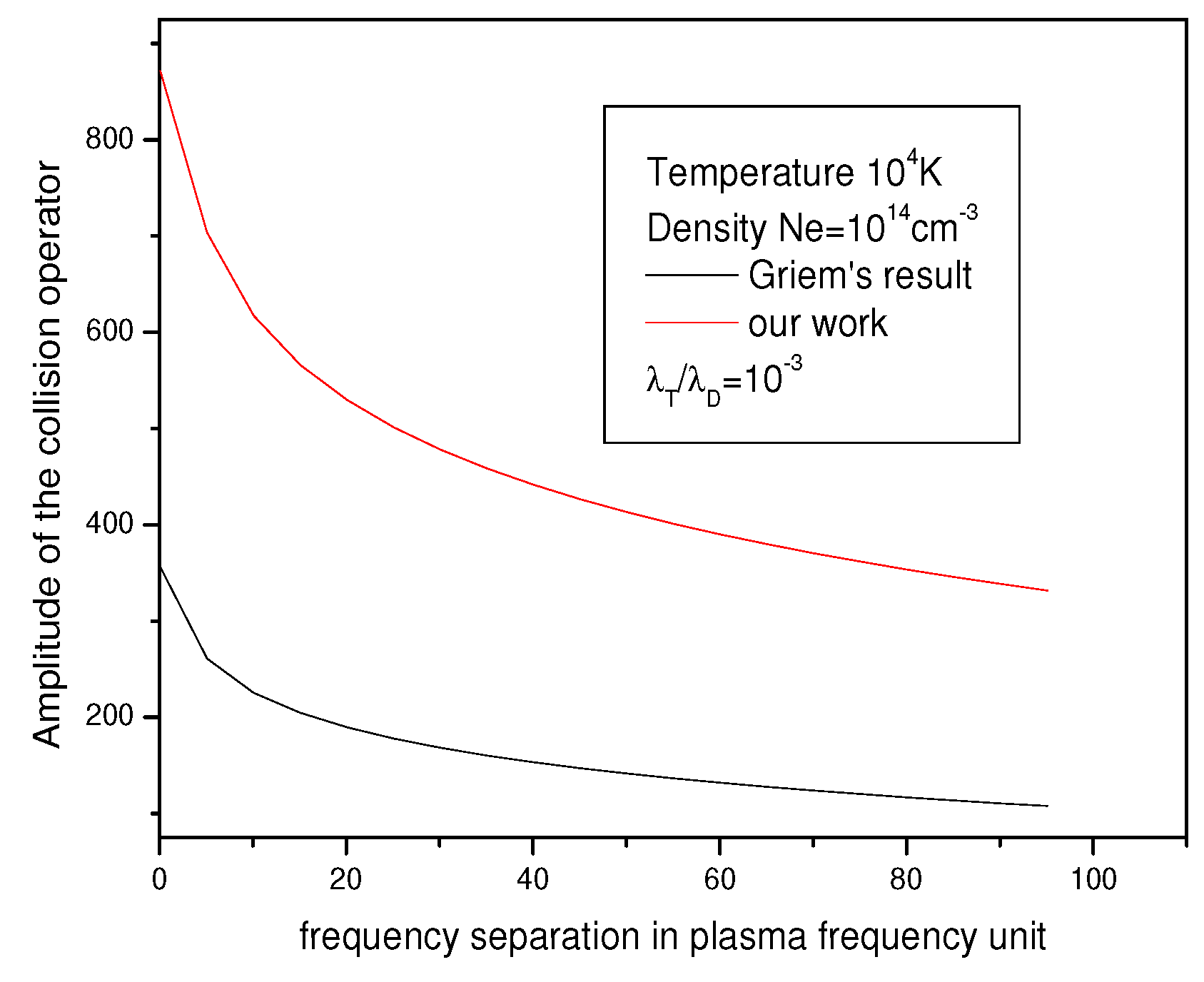
The three contributions in Equations (27), (28) and (30) of the amplitude of the collision operator are expressed in closed form, because the integrals in Equations (28) and (30) are computed exactly using the Meijer functions (see Appendix A). The obtained results are then exact and reported for certain plasma conditions (temperatures and densities) in Figure 1, Figure 2 and Figure 3. We see that depends on the electric microfield F, which means a deep correlation exists between the electron broadening and the ionic stark effect. In our application (subsequent figures), we only replace F by the Hotsmark field . However, for best results, we can keep the dependency of the collision operator on the electric microfield F and average (with respect to one microfield distribution [18]) the ionic Stark effect and the collision operator together.
To compare with our results, we write the Griem’s operator (in unit) as is defined in [2]:
by integrating over z we obtain:
where are given in Equation (22). By using the same change of variables in the above integrals in Equations (23) and (24), we find ()
where are the Meijer function given in [21].
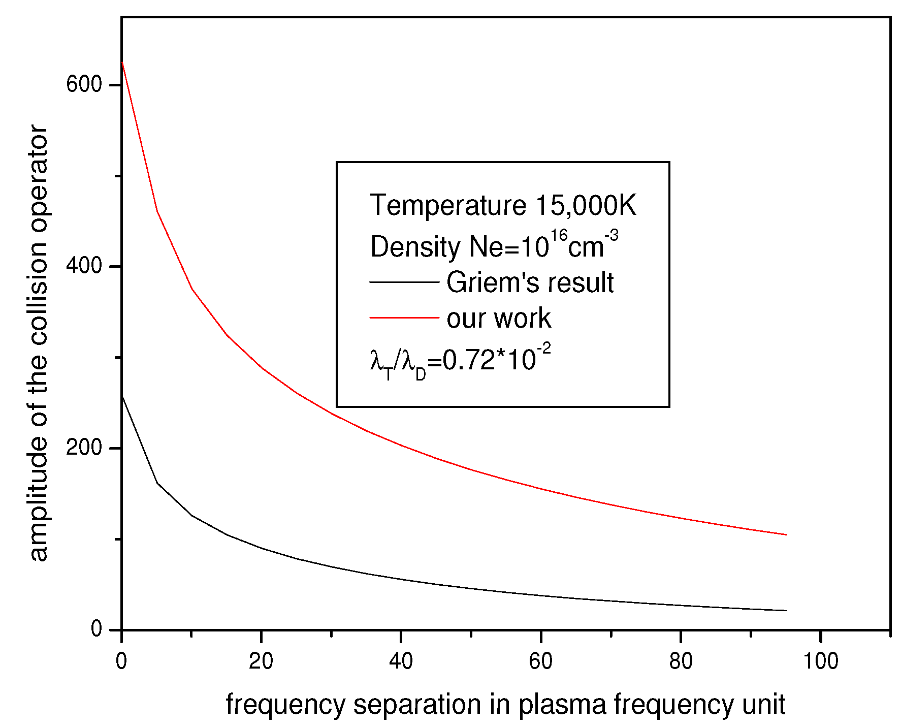
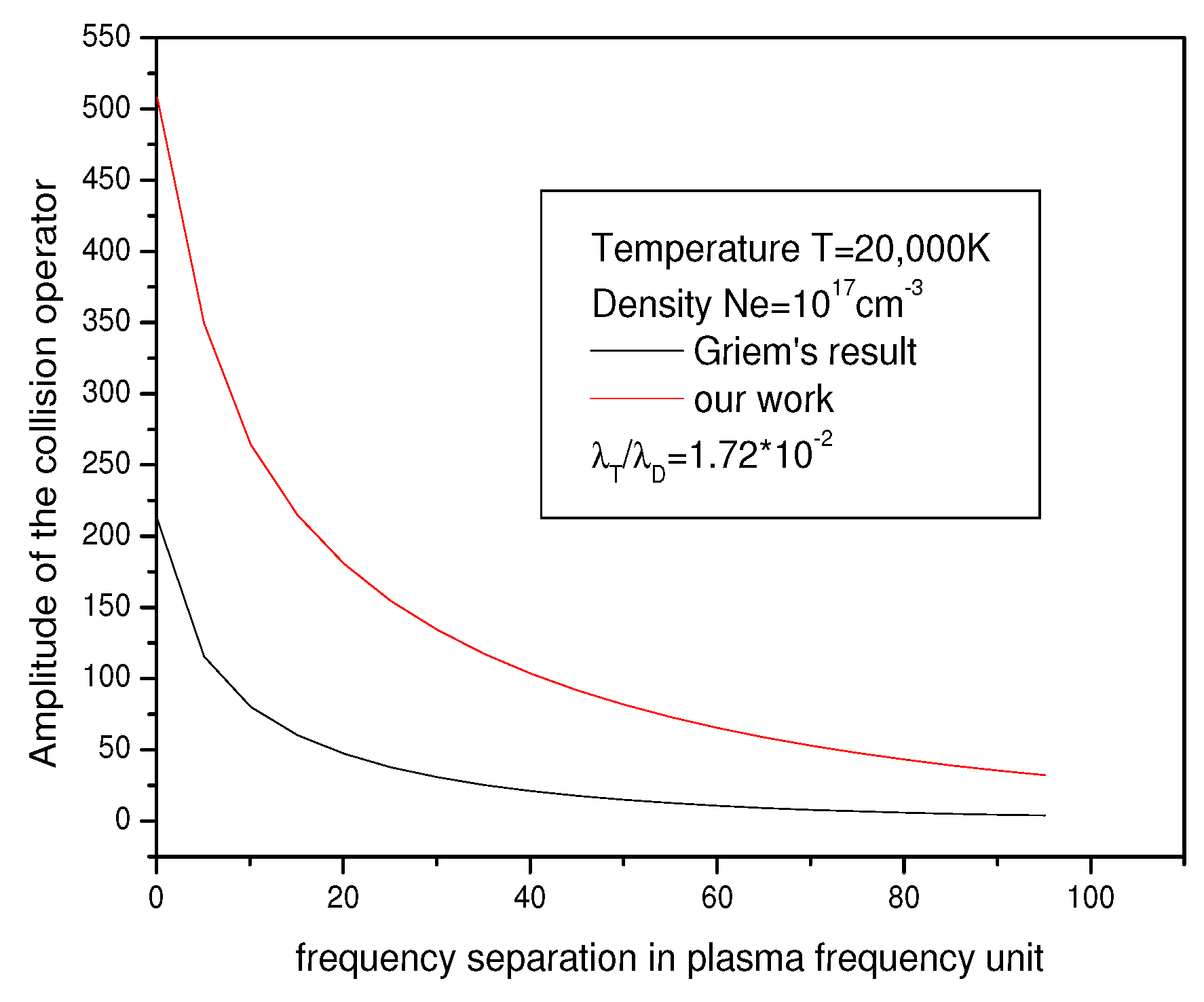
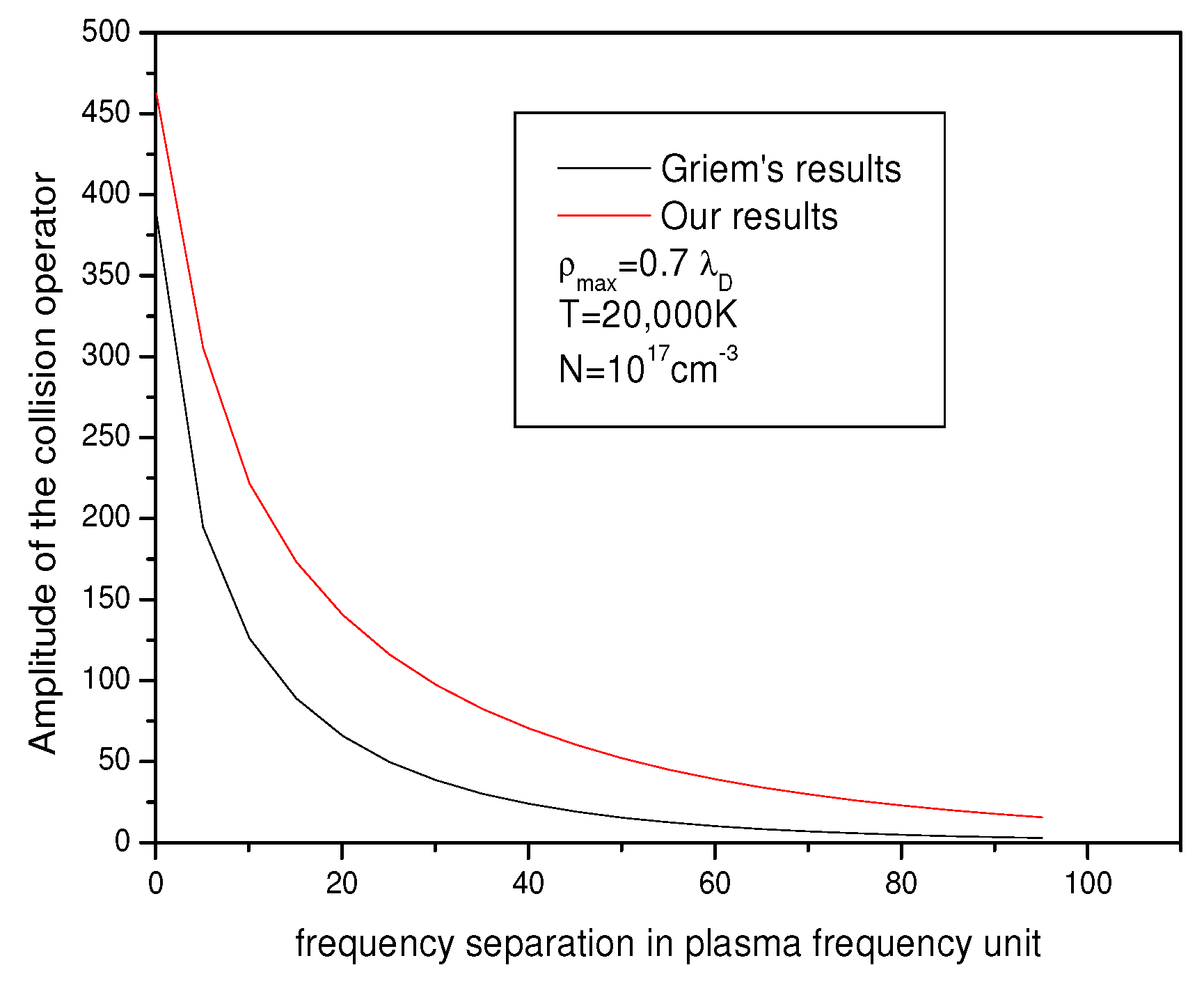
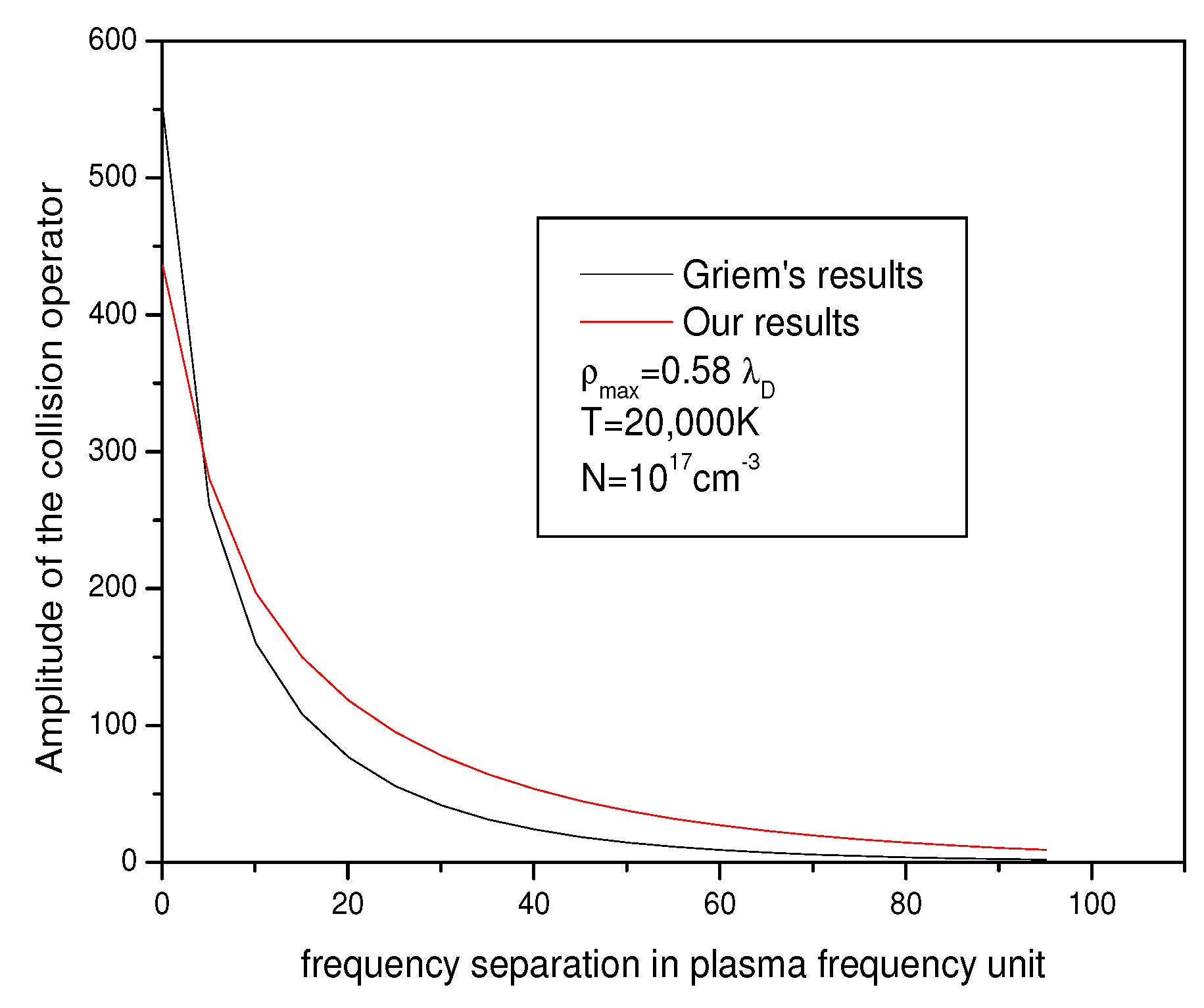
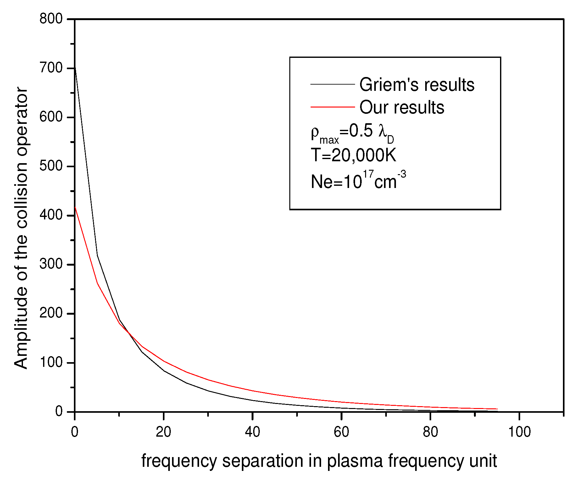
Figure 1, Figure 2 and Figure 3 show the collision operator amplitude () given by Equation (18) in arbitrary unit in terms of frequency separation (in plasma frequency unit) for various electron densities and electron temperatures and for Holtsmark electric microfield for our work and they were compared with Griem’s result. As we see, our curves have the same shape as those of Griem but they are more realistic because we consider the possible interaction between the electron and the electric microfield of the plasma during the collision between this electron and the emitter atom. More importantly, the difference between our result and Griem’s result is more pronounced for the weak frequency separations, as shown in Figure 1, Figure 2 and Figure 3. We also remark that, when the coupling parameter of plasma becomes strong, i.e., the ratio is the greatest, our collision operator is closest to the Griem values. Furthermore, we have studied the effect of the upper limit of the impact parameter on the electron collision operator. We remark that, when the upper limit is about the standard value [7], our value of the electron collision operator is greater than Griem’s (see Figure 4). This discrepancy decreases when the value of the upper limit decreases too (see Figure 5 and Figure 6).
4. Conclusions
In this work, we have considered the weak collision contribution of the electron collision operator to the spectral line profile broadening in helium plasma. By using the hypothesis that, during the collision, the electron movement is governed by the microfield F created by the ions of the plasma as well as the impact approximation for the electrons, we have computed the weak contribution of the electron collision operator. We have expressed the result in term of the Meijer’s functions. We have shown that the collision operator is a function of the ionic electric microfield F (see Equation (30)) and we have compared it, for a fixed value of the ionic electric microfield, to Griem results. This work gives then a best result for the collision operator and presents a deep relation between the electron broadening and the ionic stark broadening F. A more interesting project to study is to include in this work an external magnetic field in the movement in Equation (2) and to see how the spectral properties of the emission are modified by the presence of the magnetic field in the plasma.
Author Contributions
Y.B.N., F.K., S.D., E.S.L. and M.T.M. participated equally in this theoretical work.
Funding
This research was funded by: Ministere de l’enseignement superieur et la recherche scientifique, Algerie.
Acknowledgments
We wish to acknowledge the support of LRPPS laboratory and its director Fethi Khelfaoui, who offered us encouragement and supporting technical materials to develop this work. In addition, our acknowledgement goes to M. Koubiti for his encouragement.
Conflicts of Interest
We declare no conflicts of interest.
Appendix A
To compute the integrals in Equations (29) and (31), we use the equivalent integrals [21]
where is the Meijer function.
References
- Baranger, M. Problem of Overlapping Lines in the Theory of Pressure Broadening. Phys. Rev. 1958, 111, 494. [Google Scholar] [CrossRef]
- Griem, H.R.; Baranger, M.; Kolb, A.C.; Oertel, G. Stark Broadening of Neutral helium Lines in a Plasma. Phys. Rev. 1962, 125, 177. [Google Scholar] [CrossRef]
- Sahal-Bréchot, S. Impact Theory of the Broadening and Shift of Spectral Lines due to Electrons and Ions in a Plasma. Astron. Astrophys. 1969, 2, 322. [Google Scholar]
- Griem, H.R.; Blaha, M.; Kepple, P.C. Stark-profile calculations for Lyman-series hnes of one-electron ions in dense plasmas. Phys. Rev. A 1979, 19, 2421. [Google Scholar] [CrossRef]
- Lee, R.W. Plasma line broadening of the Lyman-α transition including ion dynamics. J. Phys. B Atom. Mol. Phys. 1978, 11, L167. [Google Scholar] [CrossRef]
- Lee, R.W. Plasma line shapes for selected transitions in hydrogen-, helium- and lithium-like ions. J. Quant. Spectrosc. Radiat. Transf. 1988, 40, 561–568. [Google Scholar] [CrossRef]
- Alexiou, S. Collision operator for isolated ion lines in the standard Stark-broadening theory with applications to the Z scaling in the Li isoelectronic series 3P-3S transition. Phys. Rev. A 1994, 49, 106. [Google Scholar] [CrossRef] [PubMed]
- Kogan, V.L.; Lisitsa, V.S.; Sholin, G.V. Spectral-line broadening in plasma. In Review of Plasma Physics; Kadomtsev, A.B.B., Ed.; Springer: Boston, MA, US, 1987. [Google Scholar]
- Konjevic, N.; Wiese, W.L. Experimental Stark Widths and Shifts for Spectral Lines of Neutral and ionized Atoms. Phys. Chem. Ref. Data 1990, 19, 1307–1385. [Google Scholar] [CrossRef]
- Kelleher, D.E.; Wiese, W.L. Observation if Ion Motion in Hydrogen Stark Profiles. Phys. Rev. Lett. 1973, 31, 1431. [Google Scholar] [CrossRef]
- Djurović, S.; Ćirišan, M.; Demura, A.V.; Demchenko, G.V.; Nikolić, D.; Gigosos, M.A.; González, M.A. Measurements of Stark central asymmetry and its analysis through standard theory and computer simulations. Phys. Rev. E 2009, 79, 046402. [Google Scholar] [CrossRef]
- Griem, H.R.; Kolb, A.; Shen, Y. Stark Broadening of Hydrogen Lines in a Plasma. Phys. Rev. 1959, 116, 4. [Google Scholar] [CrossRef]
- Alexiou, S.; Lee, R.W. Semiclassical calculations of line broadening in plasmas: Comparison with quantal results. J. Quant. Spectrosc. Radiat. Transf. 2006, 99, 10–20. [Google Scholar] [CrossRef]
- Wiese, W.L.; Kelleher, D.E.; Helbig, V. Variations in Balmer-Line Stark Profiles with atom- ion reduced mass. Phys. Rev. 1975, 11, 1854. [Google Scholar] [CrossRef]
- Ferri, S.; Calisti, A.; Mossé, C.; Rosato, J.; Talin, B.; Alexiou, S.; Gigosos, M.A.; González, M.A.; González-Herrero, D.; Lara, N.; et al. Ion Dynamics Effect on Stark Broadened Line Shapes: A Cross-Comparison of Various Models. Atoms 2014, 2, 299–318. [Google Scholar] [CrossRef]
- Godbert-Mouret, L.; Meftah, T.; Calisti, A.; Stamm, R.; Talin, B.; Gigosos, M.; Cardenoso, V.; Alexiou, S.; Lee, R.W.; Klein, L. Accuracy of Stark Broadening Calculations for Ionic Emitters. Phys. Rev. Lett. 1998, 81, 5568. [Google Scholar] [CrossRef]
- Johns, H.M.; Kilcrease, D.P.; Colgan, J.; Judge, E.J.; Barefield, J.E., II; Wiens, R.C.; Clegg, S.M. Improved electron collisional line broadening for low-temperature ions and neutrals in plasma modeling. J. Phys. B At. Mol. Opt. Phys. 2015, 48, 224009. [Google Scholar] [CrossRef]
- Iglesias, C.A.; Lebowitz, J.L.; Gowan, D.M.C. Electric microfield distributions in strongly coupled plasmas. Phys. Rev. A 1983, 28, 1667. [Google Scholar] [CrossRef]
- Hooper, C.F. Electric microfield distributions in plasmas. Phys. Rev. 1966, 149, 77. [Google Scholar] [CrossRef]
- Potekhin, A.Y.; Chabrier, G.; Gilles, D. Electric microfield distributions in electron-ion plasmas. Phys. Rev. E 2002, 65, 036412. [Google Scholar] [CrossRef] [PubMed] [Green Version]
- Gradshteyn, I.S.; Ryzhik, I.M. Table of Integrals, Series, and Products, 5th ed.; Academic Press: Boston, MA, USA, 1994. [Google Scholar]
Figure 1.
Amplitude of collision operator versus frequency separation in plasma frequency unit for Ne = 1014 cm−3 and 10,000 K. The amplitude is in unit, where A is defined in the text as Equation (26).
Figure 1.
Amplitude of collision operator versus frequency separation in plasma frequency unit for Ne = 1014 cm−3 and 10,000 K. The amplitude is in unit, where A is defined in the text as Equation (26).

Figure 2.
Amplitude of collision operator versus frequency separation in plasma frequency unit for Ne = 1016 cm−3 and 15,000 K. The amplitude is in unit, where A is defined in the text as Equation (26).
Figure 2.
Amplitude of collision operator versus frequency separation in plasma frequency unit for Ne = 1016 cm−3 and 15,000 K. The amplitude is in unit, where A is defined in the text as Equation (26).

Figure 3.
Amplitude of collision operator versus frequency separation in plasma frequency unit for Ne= and a temperature 20,000K. The amplitude is in unit, where A is defined in the text as Equation (26).
Figure 3.
Amplitude of collision operator versus frequency separation in plasma frequency unit for Ne= and a temperature 20,000K. The amplitude is in unit, where A is defined in the text as Equation (26).

Figure 4.
Amplitude of collision operator versus frequency separation in plasma frequency unit for Ne = 1017 cm−3 and a temperature 20,000 K. The amplitude is in unit where A is defined in the text as Equation (26) and .
Figure 4.
Amplitude of collision operator versus frequency separation in plasma frequency unit for Ne = 1017 cm−3 and a temperature 20,000 K. The amplitude is in unit where A is defined in the text as Equation (26) and .

Figure 5.
Amplitude of collision operator versus frequency separation in plasma frequency unit for Ne = 1017 cm−3 and a temperature 20,000 K. The amplitude is in unit where A is defined in the text as Equation (26) and .
Figure 5.
Amplitude of collision operator versus frequency separation in plasma frequency unit for Ne = 1017 cm−3 and a temperature 20,000 K. The amplitude is in unit where A is defined in the text as Equation (26) and .

Figure 6.
Amplitude of collision operator versus frequency separation in plasma frequency unit for Ne = 1017 cm−3 and a temperature 20,000 K. The amplitude is in unit where A is defined in the text as Equation (26) and .
Figure 6.
Amplitude of collision operator versus frequency separation in plasma frequency unit for Ne = 1017 cm−3 and a temperature 20,000 K. The amplitude is in unit where A is defined in the text as Equation (26) and .

© 2019 by the authors. Licensee MDPI, Basel, Switzerland. This article is an open access article distributed under the terms and conditions of the Creative Commons Attribution (CC BY) license (http://creativecommons.org/licenses/by/4.0/).
Share and Cite
MDPI and ACS Style
Ben Nana, Y.; Khelfaoui, F.; Douis, S.; Sadeghzadeh Lari, E.; Meftah, M.T. Effect of the Ions on the Electron Collision Operator through Electronic Trajectory Modification. Atoms 2019, 7, 77. https://doi.org/10.3390/atoms7030077
AMA Style
Ben Nana Y, Khelfaoui F, Douis S, Sadeghzadeh Lari E, Meftah MT. Effect of the Ions on the Electron Collision Operator through Electronic Trajectory Modification. Atoms. 2019; 7(3):77. https://doi.org/10.3390/atoms7030077
Chicago/Turabian StyleBen Nana, Yasmina, Fethi Khelfaoui, Said Douis, Eshrat Sadeghzadeh Lari, and Mohammed Tayeb Meftah. 2019. "Effect of the Ions on the Electron Collision Operator through Electronic Trajectory Modification" Atoms 7, no. 3: 77. https://doi.org/10.3390/atoms7030077
Note that from the first issue of 2016, this journal uses article numbers instead of page numbers. See further details here.