Application of Augmented Reality and Robotic Technology in Broadcasting: A Survey


School of Computer Science and Electronic Engineering, University of Essex, Wivenhoe Park, Colchester CO4 3SQ, UK
*
Author to whom correspondence should be addressed.
Robotics 2017, 6(3), 18; https://doi.org/10.3390/robotics6030018
Submission received: 26 May 2017
/
Revised: 21 July 2017
/
Accepted: 7 August 2017
/
Published: 17 August 2017
(This article belongs to the Special Issue Robotics and 3D Vision)
Abstract
:As an innovation technique, Augmented Reality (AR) has been gradually deployed in the broadcast, videography and cinematography industries. Virtual graphics generated by AR are dynamic and overlap on the surface of the environment so that the original appearance can be greatly enhanced in comparison with traditional broadcasting. In addition, AR enables broadcasters to interact with augmented virtual 3D models on a broadcasting scene in order to enhance the performance of broadcasting. Recently, advanced robotic technologies have been deployed in a camera shooting system to create a robotic cameraman so that the performance of AR broadcasting could be further improved, which is highlighted in the paper.
1. Introduction
Recently, there is an optimistic prospect on installing Augmented Reality (AR) contents in broadcasting, which is customizable, dynamic and interactive. AR aims at changing the appearance of a real environment by merging virtual contents with real-world objects. Through attaching virtual content on a real-world environment, broadcasting industries avoid physically changing the appearance of a broadcasting studio. In addition, broadcasters can tell a much more detailed and compelling story through interacting with 3D virtual models rather than with verbal descriptions only. In recent AR broadcasts, robotic technology is frequently deployed since it is more accurate, robust and stable. Furthermore, it also benefits virtual-real interactions during broadcasting, such as zooming in on a point of a virtual model, or continuously aiming at a virtual model in multiple views.
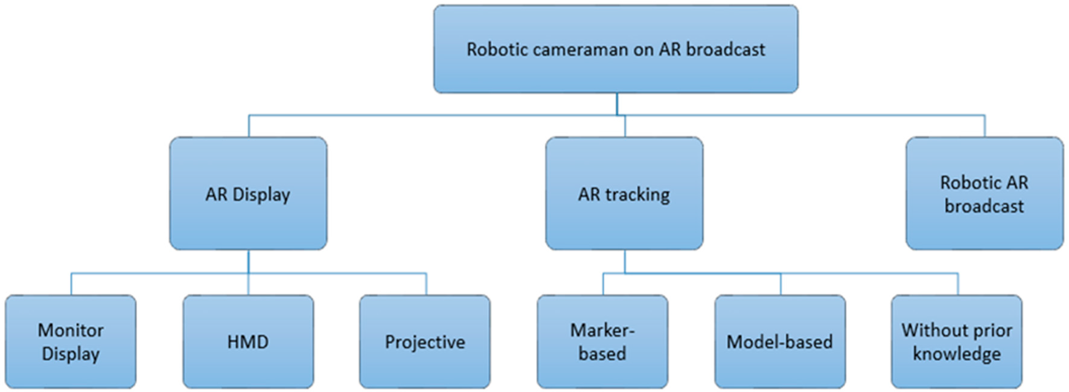
A robotic AR broadcasting system includes three key components: (i) AR display that represents the user augmented view; (ii) AR tracking that aligns virtual content with augmentation area accurately and consistently; and (iii) a robotic camera system which enables the camera to autonomously move around a broadcasting studio and consistently aim at the broadcaster. Figure 1 shows these three main components in an AR broadcasting system.
Recent AR display techniques in broadcasting are still in their developing stage, and it is mainly expressed in three types of production: the most general approach is displaying an augmented view through a monitor, which refers to monitor-display; alternatively, some researchers utilize body-attached equipment to provide to the audience a first-person perspective, such as AR glasses, which provides users with the first-person perspective and the best immersive effect; different to displaying augmented view through external devices, projection-based AR projects virtual content over real-world environments to enable an augmented view. This makes the virtual graphic directly visible for broadcasters and greatly reduces the potential broadcasting accidents.
Before overlaying dynamic virtual content onto a real-world environment, it is necessary for an AR system to be able to sense its working environment and track a user’s position relative to the recognized model or its surroundings such as 3 positioning variables and 3 rotating variables . This is referred to as the AR tracking problem [1]. Over recent decades, researchers have developed several advanced vision-based pose-tracking algorithms to define 2D/3D relationships through images, which could be divided into three phases. The marker-based approach occupied the mainstream in this field during the first phase, which continues its operation in some recent broadcasting systems until today. During the second phase, marker-less approaches have been the major focus as they are flexible, and provide a more accurate tracking performance. This approach is model-based, which is also a mature method in AR. Most recently, real-time pose estimation does not require prior-known markers or models. Instead, it addresses both tracking and reconstruction tasks simultaneously in a parallel structure, e.g., various SLAM algorithms.
Advanced robotic technologies have recently been deployed in AR broadcasts to replace qualified human operators to achieve a better performance, and there are still many challenges that are required to be overcome, including challenges on performance, accuracy and robustness for AR techniques, and challenges on automation and intelligence for robotic cameramen. This paper reviews recent techniques and development in AR broadcast, especially focused on the deployment of advanced robotic cameraman systems.
The rest of the paper is organized as follows. Section 2 introduces the recent AR display technique that is used in the initial development of AR broadcasting. In Section 3, recent popular sensors and efficient visual tracking techniques are presented, namely marker-based, model-based and tracking without prior knowledge. Section 4 outlines various in-use robotic cameraman systems in the current AR broadcasting industry. Finally, a brief conclusion is given in Section 5.
2. Display of AR Broadcast
Recent AR display techniques in broadcasting are still in the developing stage, and are mainly focused on three forms: Monitor-based, HMD (Head-mounted) and Projection-based.
2.1. Monitor-Based Applications
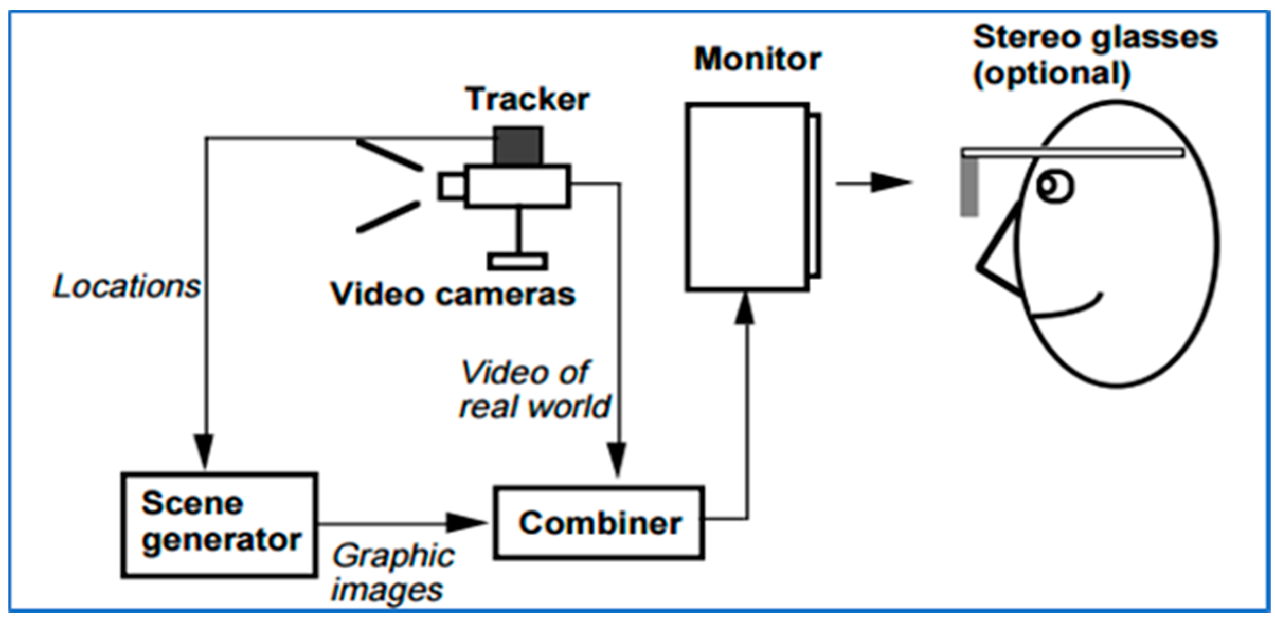
Monitor-based display enables augmented view through a monitor or other types of screens, which generally provides the viewers the third-person perspective in front of TV sets. Figure 2 shows a typical framework of monitor-displayed AR. Firstly, the real-world image is captured by camera as the inputs; then the obtained images are processed and merged with computer-generated virtual graphics in a back-stage process; and the final augmented view is displayed through screens. Since this approach requires registering the real-world environment for correctly rendering annotation, the final displayed augmented view is always delayed.
AR is firstly used as a virtual annotation on screencast of sport competitions. Virtual 1st & 10 line inserted virtual lines to indicate the yardage in American Football broadcasting in 1998. After then, AR annotation has been frequently adopted in basketball, tennis, ice hockey, etc. [1,3,4].
Recently, this AR technique is widely used to enhance appearance of broadcasting studio. Ericsson has introduced their indoor AR systems for visualizing the statistical data of sports broadcasting. By augmenting virtual contents at the front of broadcasters, they can interact with 3D virtual models and illustrate sports competition in more detail, e.g., BBC “Match of the Day” and BT sports. INDE display their interactive and touchable AR effect on large screens for education, entertainment, exhibition, etc. As an innovation, some AR systems insert virtual effect on the TV terminal or user side to enable viewers to choose between ordinary image or augmented view, as well as allowed them to design their personal AR effects while watching broadcasts [5,6,7].
2.2. HMD (Head-Mounted Display)
Wearable AR glasses are considered to be the most advanced and representative class in recent AR applications [8]. Unlike recent VR glass that provides a totally virtual environment, AR aims at merging virtual contents with real-world environments. In broadcasting, wearable AR equipment aims at overlapping multiple contents (real or virtual) onto the real world in the audience’s view, and its equipment has been designed in two forms: Video See-through (VST) HMD based on video synthesis technology and Optical See-through (OST) HMD based on optical theory, as shown in Figure 3.
Video-based See-Though HMD, VST HMD in short, has the similar working principle as monitor-based AR applications. Since the FOV of the human is larger than a normal camera, VST HMD commonly utilized omnidirectional cameras. The parallax-free VST HMD system provides a seamless VST Display [9]. Recently, AR Rift has improved the tracking performance with wide FOV camera on Oculus Rift [10]. Moreover, Optical See-Through HMD or OST HMD projects virtual contents on special curved optical combiners to merge virtual and real [11,12]. Microsoft has developed its AR headset “Hololens” for the future Sports Broadcasting, which could expand audience view and augmented live 3D virtual models inside the room.
As a comparison, VST HMD has a better compensation for brightness difference between virtual and real and perception delay errors. However, the resolution of its displayed image is limited, and its immersive effect is greatly reduced if the camera is misaligned with user’s eyes. OST HMD keeps the resolution of the real world but it is more difficult for implementation, since it needs to face lightness intensity problems; delay problems caused by superimposing virtual onto real; and resolution matching challenge.
2.3. Projector-Based Augmented Reality System
Projector-based Spatial AR technique has been developed in AR broadcasting in the past few years [13,14]. In general, projector-based AR systems enable the augmented view directly to the naked eye, and its emergence has eliminated the reliance of external equipment. As an improvement to traditional projectors, SAR allows the projection if the surface is uneven or irregular, and it creates an interactive, immersive and three-dimensional virtual environment by projecting virtual graphic over objects’ surface, 2D or 3D. Recently, “Lightform” designed a projector-based AR system to seamlessly merge virtual content with real world. Since it does not require body-attached equipment, viewers can share the experience and communicate while enjoying the AR experience [15]. Panasonic has introduced its projector-based AR system for a luxury suite at a soccer stadium: “Window Augmented Reality Projection”; the dynamic virtual content is projected on a special transparent film attached on windowpane, and this special film permits an augmented view without obscuring [16].
2.4. Summary
The characteristics of state-of-art AR broadcasting displays are reviewed in this section. In fact, no single display technique could satisfy comprehensive requirements of wide user communities. For example, monitor-based AR broadcasting has more mature applications than the others in recent years, but provides limited immersive experience. HMD has the best immersive experience, whereas it still struggles with latency, focus mechanism, brightness, accuracy and widespread acceptance problems. Projection display enables augmented view with naked eyes. However, the resolution of their projected content is hardly to achieve the real-world resolutions. A brief comparison is concluded in Table 1.
3. AR Tracking in Broadcasting
In this section, current in-use sensors of AR applications are introduced and compared firstly; then recent AR tracking approaches will be classified and concluded in three aspects: marker-based, model-based and tracking without prior knowledge.
3.1. Sensors in AR Broadcasting
With the recent advancement of sensors in scale and quality, various sensors have been implemented in AR broadcasting systems, such as optical sensors, infrared sensors, IMU (Inertial Measurement Unit), hybrid sensors (Combination of above sensors) and others.
3.1.1. Camera
Camera has been developed into various forms for AR applications recently, such as monocular camera, stereo camera, fisheye camera, and others [17]. Monocular camera is the foundation of computer vision-based applications, and its recent real-time pose estimation technique is mature. The monocular camera-based visual tracking pipeline was proposed for AR applications in [18]. Since the dense model tracking is more accurate and robust than feature-based methods apart from expensive computing, they adopted a semi-dense approach based on probabilistic depth map. By using semi-dense approach, their feature-less monocular system could reach a real-time basis with regular CPU. Alternatively, a keyframe-based monocular SLAM system was proposed for indoor AR [19], which contains a multi-homograph (global homograph, local homograph and specific homograph) algorithm to overcome camera rapid movement problem during tracking.
On the other hand, binocular vision systems are able to obtain depth information directly, and could be deployed in AR projects [20]. The early vision of stereo-type algorithm by Moravec was implemented with a monocular camera on a mobile platform in order to estimate vehicle’s ego-motion with 3D information [21]. Recently, edge feature-based tracking algorithm was used with binocular camera through ICP algorithm [22], which fits texture-less or noisy environment. Park, et al. developed a binocular camera-based object tracking framework for mobile AR [23]. The calibration problem of See-through AR with binocular camera was studied, and “paired-eyes” technique was used to support the user to align virtual and real contents [24].
Various real-time tracking and mapping algorithms have been developed for omnidirectional cameras as the performance of visual tracking could be improved with increasing camera’s field-of-view. Theoretically, a larger field-of-view allows increasing numbers of landmarks and also has a larger overlapping area between frames. This should benefit the accuracy and robustness to visual tracking applications. However, this approach does not have a desired promising result. The comparison between omnidirectional cameras and traditional cameras in terms of real-time visual tracking is firstly introduced in 2005 [25] and the results showed that omnidirectional cameras provided a more accuracy performance for indoor workspace. Recently, Zhang et al. further confirmed this point and also proved omnidirectional cameras are not suitable for outdoor applications by comparing both cameras in various datasets [5].
For AR applications, Hayash et al. designed their AR table game with an omnidirectional camera [6].By placing the card around, the camera system could recognize them in 360 degree and display their relevant virtual content on table. Omnidirectional cameras have also been implemented onto various AR broadcasting equipment and developing platform, such as Vizrt camera system and Google Tango.
3.1.2. IMU
The combination of vision and inertial sensors is inspired by the biological motion sensing system of humans. The early version of inertial sensor is the main navigation device in large-scale systems (ships and airplanes), which contains a spinning-wheel gyroscope inside [26]. Recently, the advanced MEMS (Micro-Electro-Mechanical System) technology makes inertial sensors become smaller and more accurate, and well suited to conventional camera systems for real-time tracking [7,27].
In general, MEMS IMU is consisted with three orthogonal gyroscopes and three orthogonal accelerometers to measure velocity and acceleration in 6 DOFs [28]. While it is moving with the attached device or human, it detects the linear acceleration based on accelerometer and estimate the rotational rate though gyroscopes. IMU is an efficient tool to estimate carrier’s movement, but it seriously suffers from drift errors that are accumulated over time without boundary. In addition, its performance is easily impacted by external noise, additive magnetic field and electronics. Therefore, it is necessary to combines vision or laser sensors for visual tracking tasks.
3.1.3. Infrared Sensor
Infrared Sensor (IR) is a powerful tool for localization and tracking, which could be divided into two classes: 2D sensors and 3D sensors. 2D sensor is mainly used for measuring distance through Time-of-Flight (TOF), which times the round-trip time between the emitting and the returning of infrared light. Due to infrared light has a fast transmission speed, and not sensitive to external noises. Recently, many indoor mobile robots deploy this sensor, such as “Pioneer 2” Robot.
On the other hand, 3D IR sensors have been introduced as a solid competitor, and can scan the depth information of the whole FOV at a video frame rate [29]. It is named as 3D cameras and has deployed two working principles:
- (i)
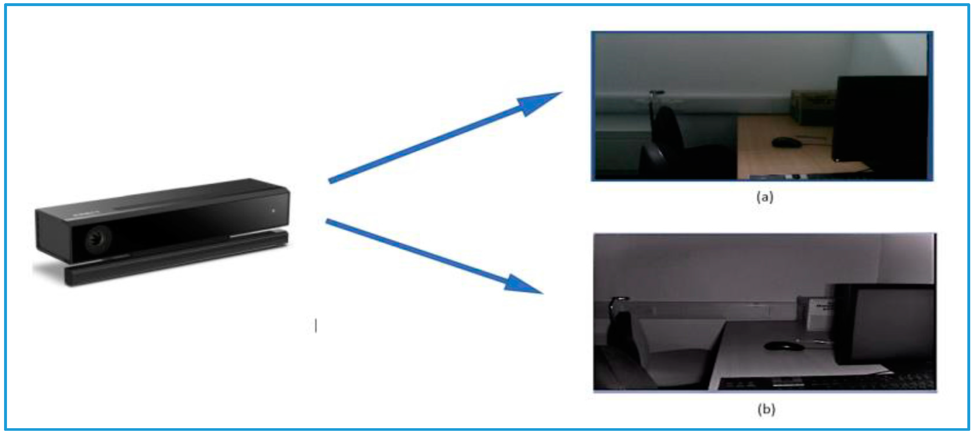
- The structure-light projection technique to obtain depth information, e.g., Kinect V1 in Figure 4a. It projects light patterns on the object surface by a LCD projector or other light source, and then calculates the distance of points by analyzing the deformation of projected patterns. Structure light projection is also popular in calibrating intrinsic and extrinsic parameter of camera-projector system [30,31].
- (ii)
- The time of flight technique to obtain depth information, as shown in Figure 4b. The TOF-based 3D camera projects laser light onto target surface and times the reflection time to measure distances of each point [23]. It works at a large range with a high accuracy. Swiss Ranger SR4000/SR4500, and Kinect V2 are two types of such sensors, which are popular.
Though 3D IR sensors provide a direct depth measurement, they can only be used for indoor applications as infrared light is strongly disturbed by sunlight. In addition, recent consumer-level 3D depth scanner is noisy and low quality, and its working range is limited in around 4 m to keep depth measurement accurate and reliable.
3.1.4. Hybrid Sensors
The current vision systems could utilize passive landmarks to calibrate, which is however generally computational expensive and less robust to occlusion. As a result, recent auto tracking systems frequently combine external sensors to improve tracking performance, such as IMU + Vision sensor for VIO tracking [34], and RGBD camera for indoor SLAM and AR.
The integration of vision and inertial sensor is introduced in early 1990s [35], and its advantages is concluded in [28]. The combination could overcome the limitation of both sides, and greatly enhances the overall performance. On the one hand, inertial sensor cannot eliminate accumulation error over time, and it loses its efficiency when the sensor moves slowly; on the other hand, vision-based tracking operates at a low speed, and may cause motion blur while increasing its moving speed. Recently, two types of combination have been used to fuse vision and IMU data, namely “Long coupled” and “Tight Coupled”. In “Long coupled”, IMU data is used to optimize feature extraction results, especially when the feature is blurry. In contrast, “Tight Coupled” method puts IMU data and vision data in a statistical filter to estimate target pose [36,37].
Similarly, fusing RGB data with laser data could greatly enhance tracking performance. Recent laser-camera sensor mainly involves two types of application. One type is similar to common feature-based Visual Odometry: camera position is tracked by sparse visual features from normal RGB images, and the laser sensor is mainly used for measuring the distance to the recognized object. For example, “Vinten” indoor broadcasting pedestal has a 2D laser scanner with 360-degree view, which could define its position by measuring the distance to three objects in the broadcasting studio. Recent AR development platform, Google Tango, combines binocular camera, 2D laser sensor, depth camera and IMU for indoor AR applications. It can measure the distance from the sensor to target, as well as the distance between two spatial points.
Moreover, RGB-D camera captures both RBG image and depth image at the same time, as shown in Figure 5. The emergence of RGB-D camera based tracking has changed the classic feature-based tracking algorithms. For example, in KinectFusion, while moving Kinect around the scene and extracting all possible data instead of sparse image feature points, the camera pose is continuously tracked with a 30 Hz frame-rate through a coarse-to-fine ICP algorithm for Augmented Reality. Similarly, Kinect++ also uses linearized ICP for pose tracking, but its prediction and calibration is based on high-quality multi-object model instead of incomplete model. Since dense point-based approach highly relies on powerful hardware, some researchers have introduced semi-dense algorithms, e.g., Semi-dense Visual Odometry has been utilized in mobile AR applications [38].
Generally, consumer-level RGB-D cameras are sensitive to noise and not very accurate, and frequently used for small AR workspace and academic research [39]. For the large scale of AR applications, it is necessary to use multiple RGB-D sensors. For example, the “RoomAlive” from Microsoft has utilized multiple RGB-D cameras for indoor projective spatial augmented reality system [40].
3.2. Marker-Based Approaches
In AR applications, 2D marker-based tracking could be considered as the fundamental technology. However, simple 2D visible marker is not always applicable in broadcasting industry, due to it requires physically changing broadcasting scene and provides limited virtual effect. To overcome these limitations, current markers have deployed advanced materials and technology, such as 2D invisible markers and 3D markers with IR-reflective material. This section introduces various types of markers and their relative tracking algorithms.
3.2.1. 2D Marker
Marker-based AR technology registers computer-generated virtual objects at marker locations to achieve an enhancement to real scene through identifying and tracking. This approach has the benefits on simple algorithm, fast calculation speed and low requirements for environment and hardware conditions. Recent 2D markers could be classified into two fields: the former case is 2D visible markers, which mainly includes template markers and barcode marker; the other covers markers which is invisible to human but recognizable for computer, like IR markers.
Template marker is a black and white 2D image, which is composed by a simple graphic inside a black boarder. It is detected through the 4 corner points on outside board and its inside content could be designed in various forms to distinguish between each other. Since it has a very simple structure, template marker is efficient and robust for simple AR applications. The most famous application of template marker AR is ARToolKit, which is firstly released in 1999 [19], as shown in Figure 6a.
Recently, Choi and his team members augmented the virtual content on marker position in broadcasting scene and demonstrated the virtual model in different views by moving the 2D marker [41]. Gaspari, et al. inserted the virtual content into video by marker to replace traditional CG effect [42]. By using 2D markers attached on the ground, the virtual content could accurately interact with audience and create an immersive AR experience. 2D barcode is an optical machine-readable pattern, which is initially designed for tagging and logistic. It is generally designed with black and white color and follows some criterions, such as DataMatrix, QR code and PDF417 are shown in Figure 6e-g respectively. As improvements to template marker, the barcode marker approach permits the marker to be partly occluded while tracking and is typically designed with a built-in matching error detection and correlation algorithm to avoid human interception. Recent 2D barcode markers include two main types: ID markers and Data Markers.
ID Marker is similar to Temple Maker, but its inside content is depth matrix constructed with binary principle, like ARTag in Figure 6b. Data Marker has a more complex inside contents to enlarge the database, such as ARToolkitPlus in Figure 6c, which is inspired by ARToolkit. However, it fails while marker is partly occluded. Recently, other square markers are developed like ARStudio Marker, Visual Code, HOM, IGD and SCR in Figure 6d [43]. Alternatively, some researchers have designed circular 2D markers, or the marker with irregular shapes shown in Figure 6h–j [44]. In this method, the center of perspective is calculated by the pixels on perimeter. Since it has more reference feature points, the system will detect marker with ease, especially when multiple circles are overlapping on each other. However, most AR applications still choose square markers, due to most of encoding standards or algorithms are squared.
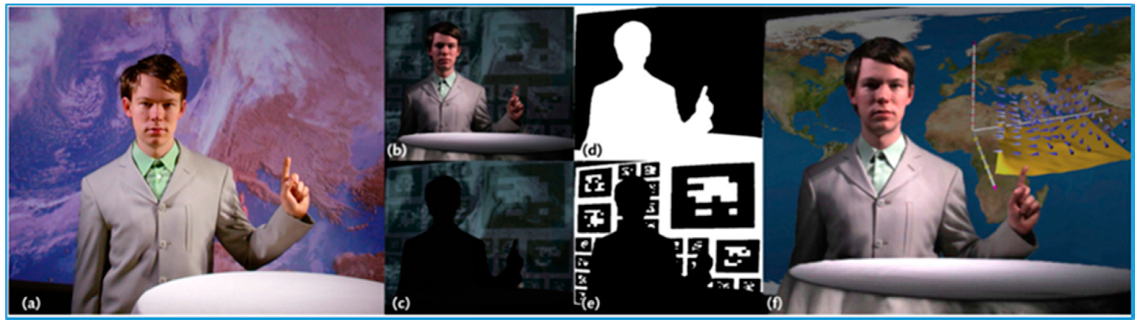
Rather than these visible markers, some of recent researches have made AR modeling more flexible and diversified through invisibility, namely invisible marker approach, such as active Infrared Light (IR) markers. There are two types of active IR markers used for AR applications mainly: Self-illuminated Marker and IR spotlight. Self-illuminate IR marker emits IR light dots by itself, and the emitted IR light could be detected by IR cameras. To encode each IR dot, SONY IC CAM system [45] encoded each light with blinking LEDs. To completely avoid placing markers in the scene, some applications project IR marker onto target surface, and then detect them by IR cameras. This method attracts interest from TV broadcast [46]. During broadcasting, IR markers are projected on broadcasting background firstly, then these markers could be recognized by IR camera and augmented with 3D virtual graphics in real-time, as shown in Figure 7.
3.2.2. 2D Marker-Based Tracking Algorithm
Typical camera pose estimation algorithm is based on the visual features extracted from camera’s views, and placing visual marker in the scene provides noticable and realiable features, which not only enhances tracking performance, but also simplfies caluculation process. As introduced above, visual markers for AR applications mainly include two types: template markers and fiducial markers, and their pose estimation methods are similar.
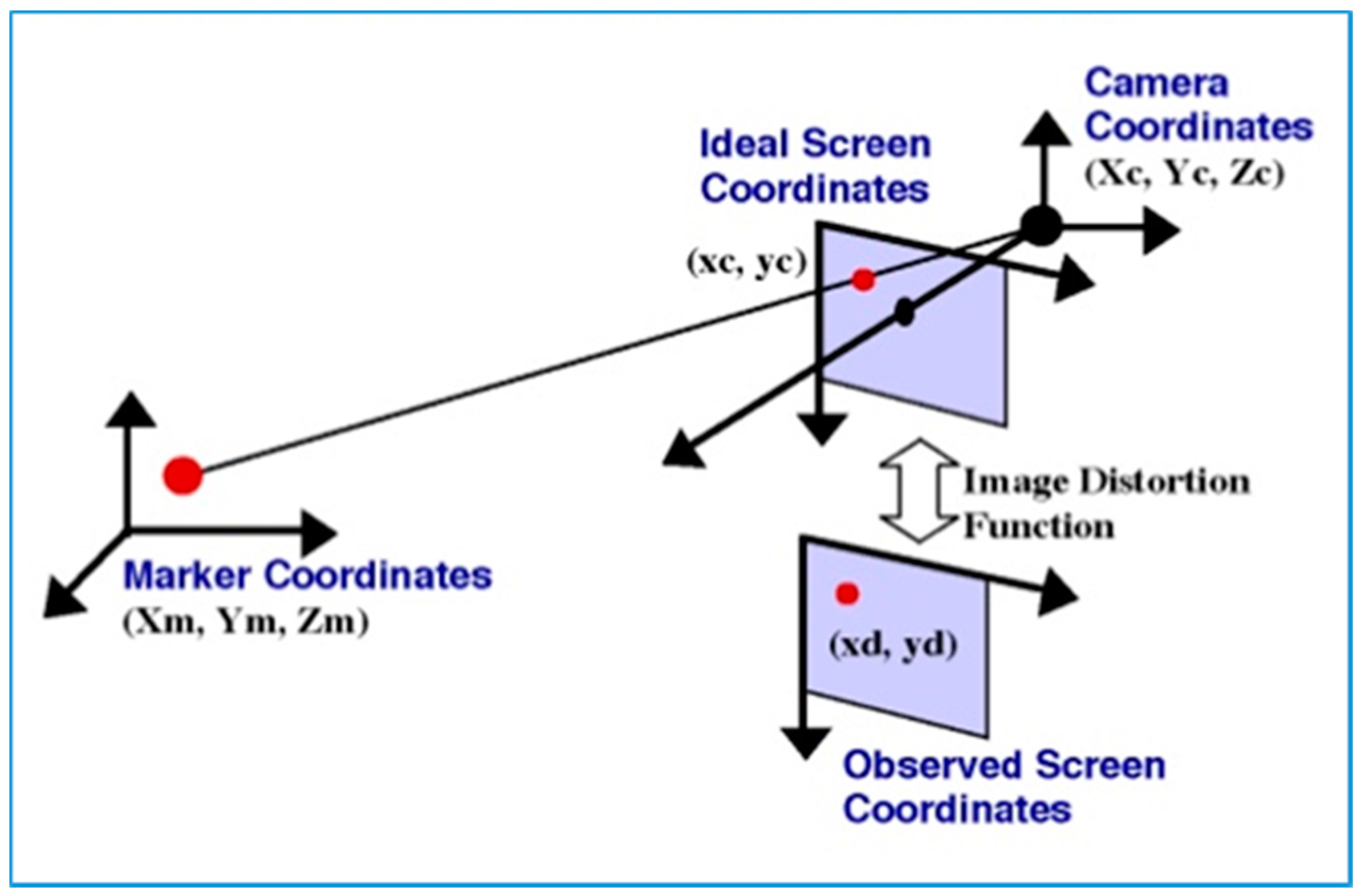
Generally, the pose of camera includes two elements: 3D translation coordinates and orientation , as shown in Figure 8. Since the camera pose transformation between two video frames could be tracked through four corresponding feature points’ pairs, the 2D marker pose could be defined by its four corner feature points. The transformation between camera and marker could be shown as:
where X is the points in world coordinates, T is transformation matrix and x is the image coordinate.
Matrix T includes coordinates transformation t and a 3 × 3 rotation matrix:
and its homogeneous coordinate is
Assume that no distortion is in camera model (most modern cameras overcome this problem) and feature points in camera coordinate is and their corresponding points in world coordinate is . In addition, then:
where K is camera calibration matrix.
Then this equation could be expressed as:
By multiply KT = E, we get:
The matrix is perspective projection matrix, to calculate this matrix, we can use:
Therefore, while N points in the scene and their relative image points are acquired, a set of 2N equations is derived.
where A is a matrix, and could be expressed as:
and L is the transpose of perspective projection matrix. Though these 12 unknown parameters could be derived through 6 detected points in the scene, this solution is not unique. Therefore, an iterative algorithm is typically utilized for more exact pose estimation.
For AR applications, Katiyar, et al. has introduced the architecture of marker-based AR technique, and also proved camera pose tracking based on visual marker is an efficient tool for simply AR applications with consumer-level sensor [48]. Khushal, et al. enabled users to try out furniture items inside an empty room with marker-based AR technique; by attaching virtual model onto an AR marker, the camera position is continuously updated and the user could view virtual furniture item in multiple perspectives [49].
To improve the robustness and accuracy, some researchers have tried multiple markers for consumer-level AR applications. Celozzi, et al. estimated camera’s position and orientation with a set of ARTag on mobile platforms, and these AR markers were projected on the wall and only visible for tracking [50]. Similarly, Grundhöfer, et al. purposed to track camera in real-time with various types (e.g., resolution and pattern) of projected IR markers in weather broadcasting program [46]. Kawakita and Nakagawa also used multiple markers to enable users a 3D view of 2D TV screenshot [51].
3.2.3. 3D Marker-based Tracking
AR Tracking-based on 2D markers remains many limitations, such as, sensitive to lighting condition, less robust to detection error, and strictly restricting movement of augmented object. As an improvement, 3D maker has been developed for enriching 3-dimensional information of the model. The most commonly used 3D marker is passive IR marker that has a spherical shape and consisted with retro-reflective material. Its 3D structure is expressed by respectively. Differing from common reflective surfaces, Retro-Reflective material reflects light in the directly opposite direction to the received light. While the IR marker is moving around the area, multiple IR sensors could very accurately detect the pose of marker and augmented correct virtual model.
Recently, 3D passive IR marker is popular in many AR/VR applications. For example, multiple filming companies and game designers use the motion tracking system of VICON to capture real human’s action. In broadcasting, Vizrt Inc. utilizes 3D Retro-reflective material marker to trigger virtual content as a more vivid method. In such a way, the broadcaster could adjust marker’s pose to show audience different view of virtual model [30].
3.3. Model-Based Approach
Model-based AR tracking explicitly uses a model or 2D template of distinguishable features. The earliest successful implementation was introduced in [31], and then its basic framework was extended into RAPiD (Real-time Attitude and Position Determination) [52]. RAPiD estimates the object’s pose through Kalman Fitler. Since it linearizes the solution, it requires the camera move slowly for good accuracy and robustness. Kermen, et al. applied the EKF framework for real-time tracking on HMD AR application [53]. Alternatively, Brown and Capson replaced normal Kalman filter with particle filter (PF) to estimate camera pose transformation. Since PF algorithm is computational expensive, they used GPU to accelerate computation process [54].
To increase tracking accuracy, various false match detection algorithms are utilized to filter out false matching feature pairs, such as RANSAC [55]. Iteratively Reweight Least Squares (IRLS), M-estimation and Lie Group Formalism have been introduced in various researches. For example, Comport, et al. integrated an M-estimator with visual control law through IRLS [56]. By inserting M-estimator, the pose tracking could effectively detect the false matches and achieve result with increasing accuracy and robustness through weighting each feature in the control law.
SFM (Structure-From-Motion) is the most popular model-based approach, which is commonly used to estimate camera pose and reconstruct 3D scene in a series of 2D images. Recently, SFM is also used to recovery 3D scene from discontinue and disorder images, such as reconstructing Roma from online pictures [57]. A classic SFM algorithm includes localization and triangulation processes. More specifically, the extracted camera pose information contributes to 3D reconstruction through triangulation; at the same time, the recovered 3D model helps to determine the camera pose by matching features correspondence. In recent studies, optimizing through bundle adjustment has been improved, like optimizing based on a subset of images, or optimizing in a parallel process [58,59]. Dong, et al. used SIFT feature descriptor in each video frame to calculate pose transformation consistently, and their purposed algorithm could achieve a real-time performance at 20 fps in a parallel thread system [41]. Whereas, satisfying the requirement of real-time performance in large-scale workspace is still a challenging problem.
Model-based tracking has been the widely adopted in AR applications as recent AR systems commonly rely on the prior knowledge, e.g., description of map or 3D models. Bleser, et al. used a CAD model of object to initial the camera’s position and obtain object’s features [60], and then the detected additional features contributed to track the camera and object frame-by-frame. Some researchers also applied IMU to precisely align virtual content to the real-world environment. Bleser proposed an AR system that combines IMU sensor with filter-based SLAM system and requires pre-knowledge of part of environment [61]. D’Ippolito, et al. integrated an IMU into an adaptive multi-rate system for visual tracking in augmented reality applications [62].
Moreover, Chandaria, et al. introduced MATRIS for AR applications in filming industry in 2007 [63], aiming at using inertial and vision sensors to replace a vision marker-based AR system. It reconstructed the 3D scene in advance with SFM. Tykkälä, et al. constructed the scene with Kinect and dense SLAM algorithm at first, then matched current frames with saved key frames to define current camera’s position and orientation [38]. Sa and Ahn proposed their unmanned aerial vehicle-based sports AR broadcast system recently [64]. By tracking the edges of tennis court, their system could locate the robot’s pose in real-time and consistently aligned virtual contents on a tennis court. Salas-Moreno, et al. used a depth camera to detect planar areas, and the detected areas were then combined to fully recover the scene [65]. To further develop AR applications, virtual images and videos were attached on the planar areas in the scene, such as the door of cabinet and walls. Moreover, a children educational broadcasting program “Ding Dong Dang Kinder Garden” was tested in [66]. With the assumption that the broadcasting scene mainly consists of planar areas and cuboids, they captured both depth data and RGB data and convert them into 3D point cloud to reconstruct scene through RANSAC plane segmentation. Besides, the RGB data is combined with virtual contents for further AR display.
3.4. Tracking without Prior Knowledge
The classic SLAM is based on Bayesian recursive filter, such as Kalman Filter and its extensions. This filter-based approach operates by inferring the current state and future state according to past and current obtained results. However, the state estimation brings uncertainty to pose estimation, increases the complexity of calculation process and slows down processing speed, especially working in large AR workplaces. In addition, the filter-based method usually estimates camera’s non-linear movement through linear model by limiting the camera movement between each time interval, which is inaccurate in practical.
Different to filter-based SLAMs, key-frame-based approach has been introduced to construct 3D model and track camera pose with BA (Bundle Adjustment), which is based on the minimization of projection error. PTAM is the one of the first model-free tracking algorithms and belongs to this field; it uses its initial view of the scene as the initial map, and then merges incremental key-frames to build 3D model through bundle adjustment [59]. At the same time, the features from captured frames are compared with stored models to define camera pose transformation. PTAM utilizes only few pixels in pose estimation, and is less robust to false matching.
As an improvement, dense-tracking approaches have been introduced for AR applications in recent years, e.g., DTAM and LSD-SLAM. DTAM belongs to key-frame-based SLAM, and allows every captured feature contributing tracking performance [67]. Since computing such large amount of pixels is very computational expensive, DTAM requires GPU to accelerate computing process to achieve a real-time basis. In contrast, LSD-SLAM associates with probabilistic semi-dense depth map for real-time tracking [68]. It estimates pose transformation by solving scale-drift alignment between two key-frames instead of estimating a rigid transformation. Recent applications has shown LSD-SLAM is a practical theory for mobile AR application [69].
Compare these two types of SLAM, key-frame-based approach outperform filter-based SLAM in both modeling and tracking performance, especially in small workplace [70,71]. Similar to SLAM, some researchers have developed VO (visual odometry) for real-time vision tracking tasks. In fact, VO could be treated as a part of SLAM algorithms apart from different working objects. The goal of Visual SLAM is tracking precise camera trajectory globally and consistently throughout the whole map, and its optimization is usually achieved by global loop closure.
In contrast, VO can track the camera pose by pose, namely “estimating local trajectory”. Recently, high-precision and consistent EKF-based Visual-Inertial Odometry has solved real-time tracking problem in unknown environments with IMU data [72]. By using MSCKF (Sliding window of poses) to present state vector in EKF formulation, it overcomes the inconsistent problem of classical EKF-based visual tracking algorithm. Zhu, et al. tracked the pose of HMD AR device in 6 DOF with EKF, and combined vision and IMU data in “tightly coupled” manner to optimize motion model [73].
3.5. Summary
This part of review outlines current in-use sensors and state-of-art tracking algorithms for AR broadcasting. Recent popular sensors include IMU, Laser Sensor, RGB Cameras and their combinations. Table 2 presents a brief discussion about general sensors being used in broadcasting systems in terms of accuracy, modularity, and flexibility.
The past tracking approaches could be divided based on different developing phases: marker-based, model-based and pose tracking without prior knowledge. More specifically,
- Marker tracking computationally inexpensive and it keeps its efficiency even working with poor quality cameras, but it requires camera keep whole 2D image inside FOV throughout tracking process.
- As an improvement, model-based approach firstly reconstructs a suitable model through scanning working environments, and then tracking camera pose by matching current obtained frame with reference frames. Rather than tracking visual markers, this approach avoids instrumenting environment, has better robustness and accuracy. It is preferred by recent AR broadcasting industries.
- Most recent camera pose tracking theory eliminates the reliance on prior knowledge (2D marker or 3D model), but it is less practical for AR application with consumer-level equipment.
4. Recent Robotic Cameraman Systems
In AR broadcasting, automatic technique could play a more vital role than manual operation. Firstly, recent broadcasting program requires cameramen to frequently interact with demonstrated virtual content, e.g., zooming at virtual model and aiming at virtual model from different angles. It is hard for human operator to do so since virtual content is not invisible. Secondly, although recent pose estimation algorithm for hand-held systems is mature, its accuracy cannot match up with the accuracy required by AR broadcasting. Therefore, robotic systems are a good solution to improve the system accuracy and achieve high-quality AR broadcasting performance. Various types of robot camera shooting systems have been developed, which is overviewed in this section.
4.1. PTZ
PTZ is short for pan (horizontal sweeping motion), tilt (vertical up and down motion) and zoom (either in or out zooming), which express the basic movement during recording. Recent advance in PTZ camera is implementing an intelligent auto tracking program that autonomously moves PTZ camera’s FOV in active style to focus on moving target [74]. With pixel variation during tracking, the camera could measure target’s movement and adjust optical lens to keep target in a clear view.
Recently, PTZ camera is popular for professional camera shooting tasks, such as filming and broadcasting. In broadcasting, PTZ camera is typically designed in small scale to track fast moving objects. For example, the Camera Corp from Vitec Videocom has experienced many sports events like Olympic Games and European Championships [75]. Alternatively, PTZ is also commonly used as a robotic pedestal and sold as a separate device without cameras, like Vinten PTZ pedestal [76]. Since it enlarges the working range and portable for other robotic systems, PTZ is treated as a necessary component in most advanced robotic cameramen.
4.2. Truck and Dolly
“Dolly” is the name comes from the old “dolly tracks”, and involves the motion of camera “Towards” or “Backwards”. For the professional camera shooting technique, the word “dolly-in” and “dolly-out” means camera step toward and step backward respectively. Similar with Dolly, Truck includes left or right movement of camera. Not to be confused with pan from PTZ pedestal, which adjust camera’s orientation without changing its Axis, truck follows target consistently while remaining its perpendicular relationship.
In professional filming, tracking target by moving dolly and truck is preferred than adjusting camera’s zoom value. One reason is truck and dolly system has a larger working range, and works in high accuracy and stability. The other reason is zooming “in” changes the focal length of camera lens, and this will cause wide-angle distortion during recording.
In recent AR broadcasting, Truck and Dolly system always combines with an external PTZ pedestal to make tracking performance much smoother. For example, Ross Video Inc. has published its trail-trolley structured robotic cameraman in current years. By moving the camera along the trail, the camera system could track the target accurately and smoothly, and provide a more seamless virtual-real scene than manual controlled camera shooting system.
4.3. Robot Arm
Robot arm is a programmable mechanical system and the imitation to human arm. A typical 6 DOF (Degree-Of-Freedom) robot arm is consisted by three jibs and three joints, allowing the robot moving in both rotation and translation. Compare with other robotic systems, robot arms have mature forward kinematics and inverse kinematics that could be used to command the camera to follow designed path in real time [77].
Since the development of robot arm technique began in 1980s, it has been successfully implemented in many industries, like Assembly Line, space research and others. In Broadcasting, MRMC (Mark Roberts Motion Control) bot. has designed arm structured robotic cameraman system, and its production is working for “Londoners”, a daily shown in UK. By using this robot, the whole recording process could be accomplished by only one operator. In 2016 Rio Olympic Game, ElectricFriends has used its robotic cameraman “EF RA” to present dynamic AR graphic during broadcasting in TV2 Norway, and its production also successfully cut down staff costs without losing program quality [78].
4.4. JIB
JIB-based structure is the basic mechanical system in filming and broadcasting, and its initial usage is providing an overlook perspective during filming. Typically, a JIB-based camera shooting system is comprised by a mobile pedestal, a lever system and a PTZ camera. With the help of lever system, the operator could move camera in a large range with small actions. Recently, STYPE has introduced their JIB-structured robotic cameraman system for AR broadcast. While operator moves camera around the studio, the robotic system delivers pan, tilt and arm position to computer and makes camera auto-aiming at virtual content consistently and fluently, which give the viewer better insight and give broadcaster the ability to dynamically interact with demonstrating news [79,80]. With a similar structure, Shotoku Broadcast industry improves the JIB-based autonomous camera tracking system with a variable structure. On the one hand, it adds the wheel-based pedestal to make the system movable; on the other hand, it has designed seven models of different length of jibs to make the pedestal system flexible in a small indoor studio or a large outdoor broadcasting scene.
4.5. Bracket
Bracket is a trail system that is commonly mounted on the ceiling or between the walls. A classic bracket system has an “H” structure, with a PTZ camera mounted on its horizontal track. During recording, the system could feedback the position and orientation data and make camera keep focusing on target consistently inside the frame. Recently, Telemetric Inc has developed its Bracket-based Robotic camera system for AR broadcasting. This system is composed with a pan-tilt pedestal and an adjustable bracket, which could be mounted on the ceiling or between the walls [81,82]. Since it requires pre-building and its working range is rigidly limited, it is less popular than other robotic systems.
4.6. Ground Moving Robot
With the development of autonomous ground mobile robots, some recent robotic cameramen have used general mobile platforms to move camera around studio. These mobile platforms eliminate the reliance on pre-built structures, such as the bracket on the wall or ceiling and the trail on the floor. In addition, they can move freely within the AR broadcasting studio. Vinten has published its APS system (Absolute Positioning system) for ground moving pedestal, which offers automatic and free navigation in all common broadcasting studios [83]. Pedestals with APS use an infrared scanner and reference targets around the studio for real-time positioning through triangulation. This allows almost instant targeting and can be 50 times faster than traditional retargeting routines. Similarly, CamBot from ROSS Video Industry emphasizes the integration and stability for AR broadcasting.
4.7. Summary
Since AR techniques require highly accurate pose tracking measurements, recent AR broadcasting industries have developed robotic camera systems as an efficient substitute to human operators. These robotic camera systems, i.e., robotic cameramen, enable a more accurate and advanced interaction with virtual content, such as zoom in virtual content and consistently aiming at virtual models in different views. Current in-use robotic cameramen have shown that they greatly improve the performance of AR broadcasting, and could be designed in multiple forms to fit various working environment.
5. Conclusions
This paper presents a comprehensive review of the state-of-art technologies embedded with AR broadcasting applications and its recent development of robotic cameraman systems. AR broadcasting include two key elements, namely AR Display and AR tracking. In some AR research papers, the latter case is further separated into AR Modelling and Real-time camera pose tracking. In recent developments of AR broadcasting, robotic cameramen become very popular since it not only greatly enhances AR performance, but also reduces the cost on manpower.
However, robotic AR broadcasting remains in its infancy and faces multiple challenges that can be summarized below:
- The first challenge is how to make AR techniques be widely deployed in the broadcasting industry successfully. Although many types of AR broadcasting concept or prototypes have been proposed recently, only monitor-displayed AR has a relative mature framework, but provided the limited immersive AR experience. Therefore, it remains to be seen that more advanced AR broadcasting equipment could provide better immersive experience and accepted by all ages of audience.
- The second challenge is how to improve the performance of AR tracking and modeling, such as robustness and accuracy. More advanced AR techniques are still waiting for development, including making the broadcaster have more realistic AR experiences and removing the model dependence in AR broadcasting.
- The third challenge is how to combine AR applications with a wider range of broadcasting programs. The current AR is mainly applied in news reporting and sports broadcasting programs. It becomes necessary to develop the potential AR applications in a wide range of broadcasting programs and make AR become an indispensable part of broadcasting.
- Last but not least, a very important research topic for the future AR broadcasting industry is how to make robotic cameramen completely autonomous so that no human involvement is required and the system accuracy could be much improved.
Author Contributions
All authors have discussed and commented on the manuscript at all stages. More specifically, Dingtian Yan collected the related literature, conducted the analysis, and completed the draft writing under the supervision of Huosheng Hu, who has also contributed to the revision of the paper structure and the presentation style, as well as the proofreading of the paper.
Conflicts of Interest
The authors declare no conflict of interest.
References
- Castle, R.O.; Klein, G.; Murray, D.W. Wide-area augmented reality using camera tracking and mapping in multiple regions. Comput. Vis. Image Underst. 2011, 115, 854–867. [Google Scholar] [CrossRef]
- Azuma, R.T. A survey of augmented reality. Presence Teleoper. Virtual Environ. 1997, 6, 355–385. [Google Scholar] [CrossRef]
- Sports Open House—Vizrt.com. Available online: http://www.vizrt.com/incoming/44949/Sports_Open_House (accessed on 5 May 2017).
- BBC Adds Augmented Reality to Euro 2012 Programs—Vizrt.com. Available online: http://www.vizrt.com/news/newsgrid/35393/BBC_adds_Augmented_Reality_to_Euro_2012_programs (accessed on 10 July 2017).
- Zhang, Z.; Rebecq, H.; Forster, C.; Scaramuzza, D. Benefit of large field-of-view cameras for visual odometry. In Proceedings of the 2016 IEEE International Conference on Robotics and Automation, Stockholm, Sweden, 16–21 May 2016; pp. 801–808. [Google Scholar]
- Hayashi, T.; Uchiyama, H.; Pilet, J.; Saito, H. An augmented reality setup with an omnidirectional camera based on multiple object detection. In Proceedings of the 20th International Conference on Pattern Recognition, Istanbul, Turkey, 23–26 August 2010; pp. 3171–3174. [Google Scholar]
- Li, M.; Mourikis, A.I. Improving the accuracy of EKF-based visual-inertial odometry. In Proceedings of the 2012 IEEE International Conference on Robotics and Automation, Saint Paul, MN, USA, 14–18 May 2012; pp. 828–835. [Google Scholar]
- Pavlik, J.V. Digital Technology and the Future of Broadcasting: Global Perspectives; Routledge: Abingdon, UK, 2015. [Google Scholar]
- Schmalstieg, D.; Hollerer, T. Augmented Reality: Principles and Practice; Addison-Wesley Professional: Boston, MA, USA, 2016. [Google Scholar]
- Steptoe, W.; Julier, S.; Steed, A. Presence and discernability in conventional and non-photorealistic immersive augmented reality. In Proceedings of the 2014 IEEE International Symposium on Mixed and Augmented Reality (ISMAR), Munich, Germany, 10–12 September 2014; pp. 213–218. [Google Scholar]
- Cakmakci, O.; Rolland, J. Head-worn displays: A review. J. Disp. Technol. 2006, 2, 199–216. [Google Scholar] [CrossRef]
- Kress, B.; Starner, T. A review of head-mounted displays (HMD) technologies and applications for consumer electronics. In SPIE Defense, Security, and Sensing; International Society for Optics and Photonics: Bellingham, WA, USA, 2013. [Google Scholar]
- Raskar, R.; Welch, G.; Fuchs, H. Spatially augmented reality. In Proceedings of the First IEEE Workshop on Augmented Reality, San Francisco, CA, USA, 1 November 1998; pp. 11–20. [Google Scholar]
- Bimber, O.; Raskar, R. Spatial Augmented Reality: Merging Real and Virtual Worlds; CRC Press: Boca Raton, FL, USA, 2005. [Google Scholar]
- Kipper, G.; Rampolla, J. Augmented Reality: An Emerging Technologies Guide to AR; Elsevier: Amsterdam, The Netherlands, 2012. [Google Scholar]
- Harrison, C. How Panasonic Can Use Stadium Suite Windows for Augmented Reality Projection During Games. Available online: https://www.sporttechie.com/panasonic-unveils-augmented-reality-projection-prototype-for-suite-level-windows/ (accessed on 20 January 2017).
- Moemeni, A. Hybrid Marker-Less Camera Pose Tracking with Integrated Sensor Fusion; De Montfort University: Leicester, UK, 2014. [Google Scholar]
- Engel, J.; Sturm, J.; Cremers, D. Semi-Dense Visual Odometry for a Monocular Camera. In Proceedings of the 2013 IEEE International Conference on Computer Vision, Sydney, Australia, 1–8 December 2013; pp. 1449–1456. [Google Scholar]
- Liu, H.; Zhang, G.; Bao, H. Robust Keyframe-based Monocular SLAM for Augmented Reality. In Proceedings of the 2016 IEEE International Symposium on Mixed and Augmented Reality, Merida, Mexico, 19–23 September 2016; pp. 1–10. [Google Scholar]
- Scaramuzza, D.; Fraundorfer, F. Visual odometry [tutorial]. IEEE Robot. Autom. Mag. 2011, 18, 80–92. [Google Scholar] [CrossRef]
- Moravec, H.P. Obstacle Avoidance and Navigation in the Real World by a Seeing Robot Rover; DTIC Document No. STAN-CS-80-813; Stanford University California Department Computer Science: Stanford, CA, USA, 1980. [Google Scholar]
- Tomono, M. Robust 3D SLAM with a stereo camera based on an edge-point ICP algorithm. In Proceedings of the IEEE International Conference on Robotics and Automation, Kobe, Japan, 12–17 May 2009; pp. 4306–4311. [Google Scholar]
- Park, J.; Seo, B.-K.; Park, J.-I. Binocular mobile augmented reality based on stereo camera tracking. J. Real Time Image Process. 2016, 1–10. [Google Scholar] [CrossRef]
- Wu, W.; Tošić, I.; Berkner, K.; Balram, N. Depth-disparity calibration for augmented reality on binocular optical see-through displays. In Proceedings of the 6th ACM Multimedia Systems Conference, Portland, Oregon, 18–20 March 2015; pp. 120–129. [Google Scholar]
- Streckel, B.; Koch, R. Lens model selection for visual tracking. In Joint Pattern Recognition Symposium; Springer: Berlin, Germany, 2005; pp. 41–48. [Google Scholar]
- Inertial Navigation Systems Information. Engineering360. Available online: http://www.globalspec.com/learnmore/sensors_transducers_detectors/tilt_sensing/inertial_gyros (accessed on 20 May 2017).
- Scaramuzza, D.; Achtelik, M.C.; Doitsidis, L.; Friedrich, F.; Kosmatopoulos, E.; Martinelli, A.; Achtelik, M.W.; Chli, M.; Chatzichristofis, S.; Kneip, L. Vision-controlled micro flying robots: From system design to autonomous navigation and mapping in GPS-denied environments. IEEE Robot. Autom. Mag. 2014, 21, 26–40. [Google Scholar] [CrossRef]
- Corke, P.; Lobo, J.; Dias, J. An Introduction to Inertial and Visual Sensing; Sage Publications: London, UK, 2007. [Google Scholar]
- Deyle, T. Low-Cost Depth Cameras (Aka Ranging Cameras or RGB-D Cameras) to Emerge in 2010? Hizook, 2010. Available online: http://www.hizook.com/blog/2010/03/28/low-cost-depth-cameras-aka-ranging-cameras-or-rgb-d-cameras-emerge-2010 (accessed on 29 April 2017).
- VizrtVideos. The Vizrt Public Show at IBC 2013 Featuring Viz Virtual Studio: YouTube. San Bruno, CA, USA. Available online: https://www.youtube.com/watch?v=F89pxcyRbe8 (accessed on 30 September 2013).
- Gennery, D.B. Visual tracking of known three-dimensional objects. Int. J. Comput. Vis. 1992, 7, 243–270. [Google Scholar] [CrossRef]
- Centre for Sports Engineering Research. How the Kinect Works Depth Biomechanics. Sheffield Hallam University: Sheffield, UK. Available online: http://www.depthbiomechanics.co.uk/?p=100 (accessed on 22 May 2017).
- NeoMetrix. What You Need to Know about 3D Scanning—NeoMetrixl. NeoMetrix Technologies Inc.: Lake Mary, FL, USA. Available online: http://3dscanningservices.net/blog/need-know-3d-scanning/ (accessed on 21 July 2016).
- Jianjun, G.; Dongbing, G. A direct visual-inertial sensor fusion approach in multi-state constraint Kalman filter. In Proceedings of the 34th Chinese Control Conference, Hangzhou, China, 28–30 July 2015; pp. 6105–6110. [Google Scholar]
- Viéville, T.; Faugeras, O.D. Cooperation of the inertial and visual systems. In Traditional and Non-Traditional Robotic Sensors; Springer: Berlin, Germany, 1990; pp. 339–350. [Google Scholar]
- Oskiper, T.; Samarasekera, S.; Kumar, R. Multi-sensor navigation algorithm using monocular camera, IMU and GPS for large scale augmented reality. In Proceedings of the 2012 IEEE International Symposium on Mixed and Augmented Reality, Atlanta, GA, USA, 5–8 November 2012; pp. 71–80. [Google Scholar]
- Gui, J.; Gu, D.; Wang, S.; Hu, H. A review of visual inertial odometry from filtering and optimisation perspectives. Adv. Robot. 2015, 29, 1289–1301. [Google Scholar] [CrossRef]
- Tykkälä, T.; Hartikainen, H.; Comport, A.I.; Kämäräinen, J.-K. RGB-D Tracking and Reconstruction for TV Broadcasts. In Proceedings of the International Conference on Computer Vision Theory and Applications (VISAPP) (2), Barcelona, Spain, 21–24 February 2013; pp. 247–252. [Google Scholar]
- Li, R.; Liu, Q.; Gui, J.; Gu, D.; Hu, H. Indoor relocalization in challenging environments with dual-stream convolutional neural networks. IEEE Trans. Autom. Sci. Eng. 2017. [Google Scholar] [CrossRef]
- Wilson, A.D.; Benko, H. Projected Augmented Reality with the RoomAlive Toolkit. In Proceedings of the 2016 ACM International Conference on Interactive Surfaces and Spaces (Iss 2016), Niagara Falls, ON, Canada, 6–9 November 2016; pp. 517–520. [Google Scholar]
- Dong, Z.; Zhang, G.; Jia, J.; Bao, H. Keyframe-based real-time camera tracking. In Proceedings of the 2009 IEEE 12th International Conference on Computer Vision, Kyoto, Japan, 29 September–2 October 2009; pp. 1538–1545. [Google Scholar]
- De Gaspari, T.; Sementille, A.C.; Vielmas, D.Z.; Aguilar, I.A.; Marar, J.F. ARSTUDIO: A virtual studio system with augmented reality features. In Proceedings of the 13th ACM SIGGRAPH International Conference on Virtual-Reality Continuum and Its Applications in Industry, Shenzhen, China, 30 November–2 December 2014; pp. 17–25. [Google Scholar]
- Rohs, M. Marker-based embodied interaction for handheld augmented reality games. J. Virtual Real. Broadcast. 2007, 4, 1860–2037. [Google Scholar]
- Naimark, L.; Foxlin, E. Circular data matrix fiducial system and robust image processing for a wearable vision-inertial self-tracker. In Proceedings of the International Symposium on Mixed and Augmented Reality, Darmstadt, Germany, 1 October 2002; pp. 27–36. [Google Scholar]
- Matsushita, N.; Hihara, D.; Ushiro, T.; Yoshimura, S.; Rekimoto, J.; Yamamoto, Y. ID CAM: A smart camera for scene capturing and ID recognition. In Proceedings of the Second IEEE and ACM International Symposium on Mixed and Augmented Reality, Tokyo, Japan, 10 October 2003; pp. 227–236. [Google Scholar]
- Grundhöfer, A.; Seeger, M.; Hantsch, F.; Bimber, O. Dynamic adaptation of projected imperceptible codes. In Proceedings of the 6th IEEE and ACM International Symposium on Mixed and Augmented Reality, Nara, Japan, 13–16 November 2007; IEEE Computer Society: Washington, DC, USA, 2007. [Google Scholar]
- Bruce Thomas, M.B. COMP 4010 Lecture10: AR Tracking; University of South Australia: Adlaide, Australia, 2016. [Google Scholar]
- Seungjun, K.; Jongeun, C.; Jongphil, K.; Jeha, R.; Seongeun, E.; Mahalik, N.P.; Byungha, A. A novel test-bed for immersive and interactive broadcasting production using augmented reality and haptics. IEICE Trans. Inf. Syst. 2006, 89, 106–110. [Google Scholar]
- Khairnar, K.; Khairnar, K.; Mane, S.; Chaudhari, R.; Professor, U. Furniture Layout Application Based on Marker Detection and Using Augmented Reality. Int. Res. J. Eng. Technol. 2015, 2, 540–544. [Google Scholar]
- Celozzi, C.; Paravati, G.; Sanna, A.; Lamberti, F. A 6-DOF ARTag-based tracking system. IEEE Trans. Consum. Electron. 2010, 56. [Google Scholar] [CrossRef]
- Kawakita, H.; Nakagawa, T. Augmented TV: An augmented reality system for TV programs beyond the TV screen. In Proceedings of the 2014 International Conference on Multimedia Computing and Systems, Marrakech, Morocco, 14–16 April 2014; pp. 955–960. [Google Scholar]
- Harris, C. Tracking with rigid models. In Active Vision; MIT Press: Cambridge, MA, USA, 1993. [Google Scholar]
- Kermen, A.; Aydin, T.; Ercan, A.O.; Erdem, T. A multi-sensor integrated head-mounted display setup for augmented reality applications. In Proceedings of the 3DTV-Conference: The True Vision-Capture, Transmission and Display of 3D Video (3DTV-CON), Lisbon, Portugal, 8–10 July 2015; pp. 1–4. [Google Scholar]
- Brown, J.A.; Capson, D.W. A framework for 3D model-based visual tracking using a GPU-accelerated particle filter. IEEE Trans. Vis. Comput. Gr. 2012, 18, 68–80. [Google Scholar] [CrossRef] [PubMed]
- Zisserman, M.A.A. Robust object tracking. In Proceedings of the Asian Conference on Computer Vision, Singapore, 5–8 December 1995; pp. 58–61. [Google Scholar]
- Comport, A.I.; Marchand, E.; Pressigout, M.; Chaumette, F. Real-time markerless tracking for augmented reality: The virtual visual servoing framework. IEEE Trans. Vis. Comput. Gr. 2006, 12, 615–628. [Google Scholar] [CrossRef] [PubMed]
- Agarwal, S.; Furukawa, Y.; Snavely, N.; Simon, I.; Curless, B.; Seitz, S.M.; Szeliski, R. Building rome in a day. Commun. ACM 2011, 54, 105–112. [Google Scholar] [CrossRef]
- Cornelis, K. From Uncalibrated Video to Augmented Reality; ESAT-PSI, Processing Speech and Images; K.U.Leuven: Leuven, Belgium, 2004. [Google Scholar]
- Klein, G.; Murray, D. Parallel tracking and mapping for small AR workspaces. In Proceedings of the 6th IEEE and ACM International Symposium on Mixed and Augmented Reality, Nara, Japan, 13–16 November 2007; pp. 225–234. [Google Scholar]
- Bleser, G.; Wuest, H.; Stricker, D. Online camera pose estimation in partially known and dynamic scenes. In Proceedings of the IEEE/ACM International Symposium on Mixed and Augmented Reality, Santa Barbard, CA, USA, 22–25 October 2006; pp. 56–65. [Google Scholar]
- Bleser, G. Towards Visual-Inertial Slam for Mobile Augmented Reality; Verlag Dr. Hut: München, Germany, 2009. [Google Scholar]
- D’Ippolito, F.; Massaro, M.; Sferlazza, A. An adaptive multi-rate system for visual tracking in augmented reality applications. In Proceedings of the 2016 IEEE 25th International Symposium on Industrial Electronics (ISIE), Santa Clara, CA, USA, 8–10 June 2016; pp. 355–361. [Google Scholar]
- Chandaria, J.; Thomas, G.; Bartczak, B.; Koeser, K.; Koch, R.; Becker, M.; Bleser, G.; Stricker, D.; Wohlleber, C.; Felsberg, M. Realtime camera tracking in the MATRIS project. SMPTE Motion Imaging J. 2007, 116, 266–271. [Google Scholar] [CrossRef]
- Sa, I.; Ahn, H.S. Visual 3D model-based tracking toward autonomous live sports broadcasting using a VTOL unmanned aerial vehicle in GPS-impaired environments. Int. J. Comput. Appl. 2015, 122. [Google Scholar] [CrossRef]
- Salas-Moreno, R.F.; Glocker, B.; Kelly, P.H.J.; Davison, A.J. Dense Planar SLAM. In Proceedings of the 2014 IEEE International Symposium on Mixed and Augmented Reality (Ismar)—Science and Technology, Munich, Germany, 10–12 September 2014; pp. 157–164. [Google Scholar]
- Cho, H.; Jung, S.-U.; Jee, H.-K. Real-time interactive AR system for broadcasting. In Proceedings of the Virtual Reality (VR), Los Angeles, CA, USA, 18–22 March 2017; pp. 353–354. [Google Scholar]
- Newcombe, R.A.; Lovegrove, S.J.; Davison, A.J. DTAM: Dense tracking and mapping in real-time. In Proceedings of the 2011 IEEE International Conference on Computer Vision (ICCV), Barcelona, Spain, 6–13 November 2011; pp. 2320–2327. [Google Scholar]
- Engel, J.; Schöps, T.; Cremers, D. LSD-SLAM: Large-scale direct monocular SLAM. In Proceedings of the European Conference on Computer Vision, Zurich, Switzerland, 6–12 September 2014; pp. 834–849. [Google Scholar]
- Schöps, T.; Engel, J.; Cremers, D. Semi-dense visual odometry for AR on a smartphone. In Proceedings of the 2014 IEEE International Symposium on Mixed and Augmented Reality (ISMAR), Munich, Germany, 10–12 September 2014; pp. 145–150. [Google Scholar]
- Strasdat, H.; Montiel, J.; Davison, A.J. Real-time monocular SLAM: Why filter? In Proceedings of the 2010 IEEE International Conference on Robotics and Automation (ICRA), Anchorage, AK, USA, 3–7 May 2010; pp. 2657–2664. [Google Scholar]
- Strasdat, H.; Montiel, J.M.; Davison, A.J. Visual SLAM: Why Filter? Image Vis. Comput. 2012, 30, 65–77. [Google Scholar] [CrossRef]
- Li, M.; Mourikis, A.I. High-precision, consistent EKF-based visual-inertial odometry. Int. J. Robot. Res. 2013, 32, 690–711. [Google Scholar] [CrossRef]
- Zhu, Z.; Branzoi, V.; Wolverton, M.; Murray, G.; Vitovitch, N.; Yarnall, L.; Acharya, G.; Samarasekera, S.; Kumar, R. AR-mentor: Augmented reality based mentoring system. In Proceedings of the 2014 IEEE International Symposium on Mixed and Augmented Reality (ISMAR), Munich, Germany, 10–12 September 2014; pp. 17–22. [Google Scholar]
- Jeong, C.-J.; Park, G.-M. Real-time Auto Tracking System using PTZ Camera with DSP. Int. J. Adv. Smart Converg. 2013, 2, 32–35. [Google Scholar] [CrossRef]
- Ltd, C.C. Camera Corps Announces Q3 Advanced Compact Robotic Camera. Camera Corpts Ltd.: Byfleet, Surrey, UK. Available online: http://www.cameracorps.co.uk/news/camera-corps-announces-q3-advanced-compact-robotic-camera (accessed on 3 May 2017).
- Vinten. Vinten Vantage—Revolutionary Compact Robotic Head. Richmond, UK. Available online: http://vantage.vinten.com (accessed on 23 May 2017).
- Patidar, V.; Tiwari, R. Survey of robotic arm and parameters. In Proceedings of the 2016 International Conference on Computer Communication and Informatics (ICCCI), Coimbatore, India, 7–9 January 2016; pp. 1–6. [Google Scholar]
- Inc, E.F. Short Presentation—Electricfriends. Bergen, Norway. Available online: http://www.electricfriends.net/portfolio/short-presentation/ (accessed on 27 March 2017).
- Grip, S. Technical Specifications—Stype Grip. Available online: http://www.stypegrip.com/technical-specifications/ (accessed on 20 May 2017).
- As, S.N. 3D Virtual Studio/Augmented Reality System—The Stype Kit. Stype Noway AS. Available online: https://www.youtube.com/watch?v=d8ktVGkHAes (accessed on 20 May 2013).
- Inc T. Elevating Wall Mount Camera Robot-Telemetrics Inc.: Jacksonville, FL, USA. Available online: http://www.telemetricsinc.com/products/camera-robotics/elevating-wall-mount-system/elevating-wall-mount-system/elevating-wall-mount (accessed on 10 May 2017).
- Beacham, F. Cost-Cutting Boosts the Use of Robots in Television Studios—The Broadcast Bridge—Connecting IT to Broadcast. Banbury, UK. Available online: https://www.thebroadcastbridge.com/content/entry/823/cost-cutting-boosts-the-use-of-robots-in-television-studios (accessed on 25 May 2017).
- Ltd, D.P.S. TVB Upgrade Studios with Vinten Radamec and Power Plus VR Camera Tracking. Digital Precision Systems Ltd. Available online: http://www.dpshk.com/news/tvb-upgrade-studios-vinten-radamec-power-plus-vr-camera-tracking (accessed on 2 March 2017).
Figure 1.
Typical embedded techniques for AR broadcast.

Figure 2.
Typical concept of Monitor-Displayed AR [2].
Figure 2.
Typical concept of Monitor-Displayed AR [2].

Figure 3.
(a) Typical Concept of Video See-Through HMD [2]; (b) Typical Concept of Optical See-Through HMD [2].
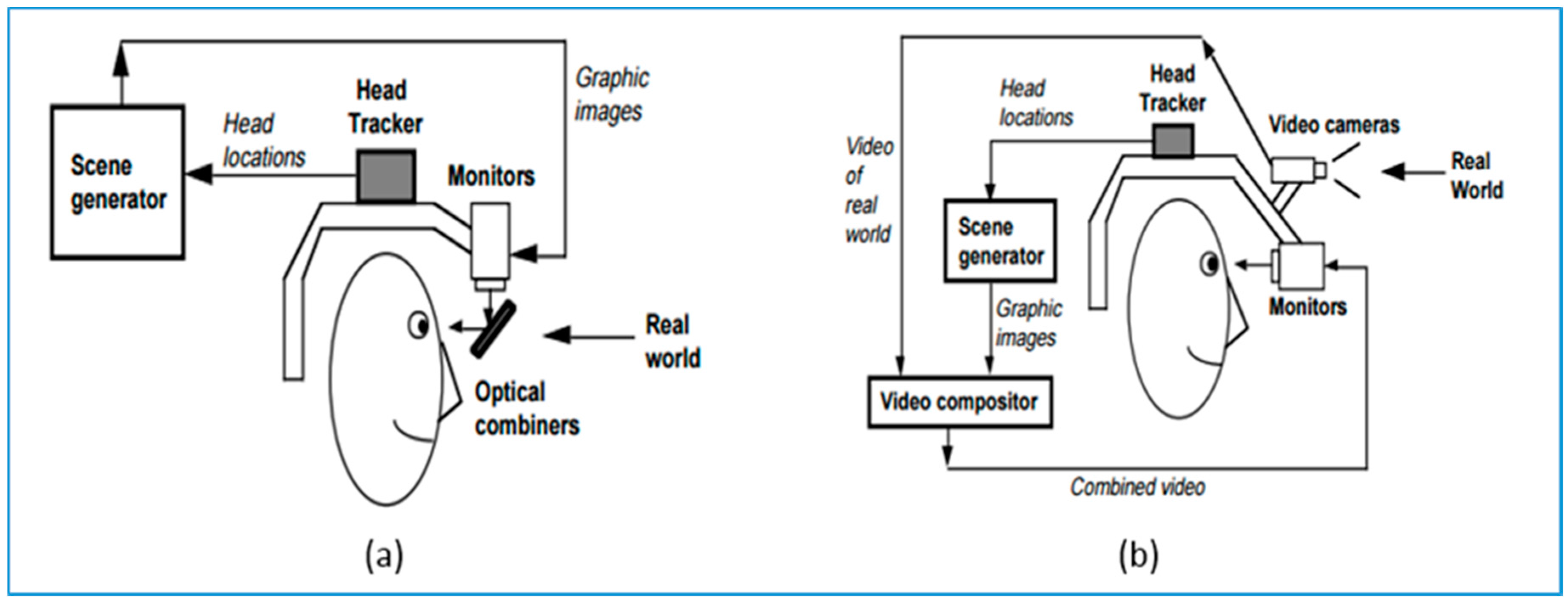
Figure 4.
Recent depth scanning technique. (a) Structured light projection algorithm from KINECT V1 [32]; (b) Working principle of TOF-based 3D camera [33].
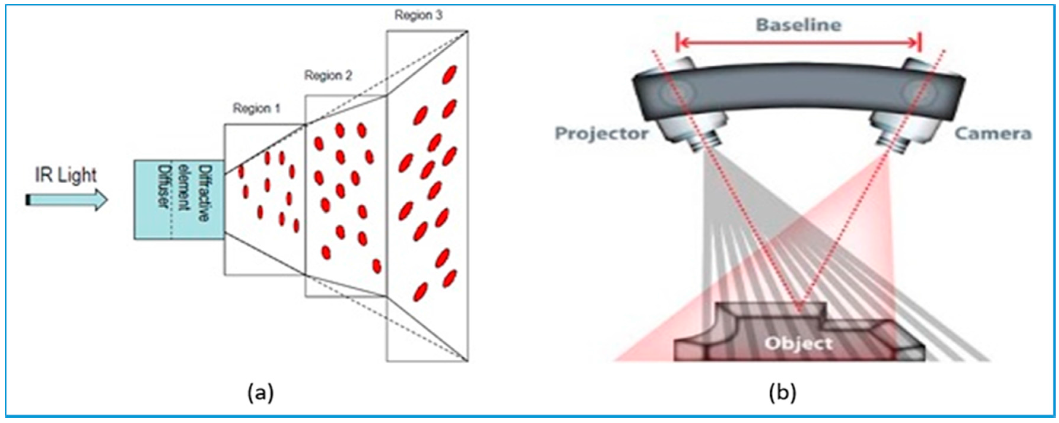
Figure 5.
Kinect V2: common consumer-level RGB-D camera. It obtains both (a) RGB frames and (b) Depth Image at a video frame rate.
Figure 5.
Kinect V2: common consumer-level RGB-D camera. It obtains both (a) RGB frames and (b) Depth Image at a video frame rate.

Figure 6.
Main coding strategy of Data Marker. (a) ARToolkit; (b) ARTag; (c) ARToolKitPlus; (d) SCR Marker; (e) Data Matrix; (f) QR Code; (g) PDF 417; (h) Intersense IS-1200 Marker; (i) Shotcode; (j) RealTIVision.
Figure 6.
Main coding strategy of Data Marker. (a) ARToolkit; (b) ARTag; (c) ARToolKitPlus; (d) SCR Marker; (e) Data Matrix; (f) QR Code; (g) PDF 417; (h) Intersense IS-1200 Marker; (i) Shotcode; (j) RealTIVision.
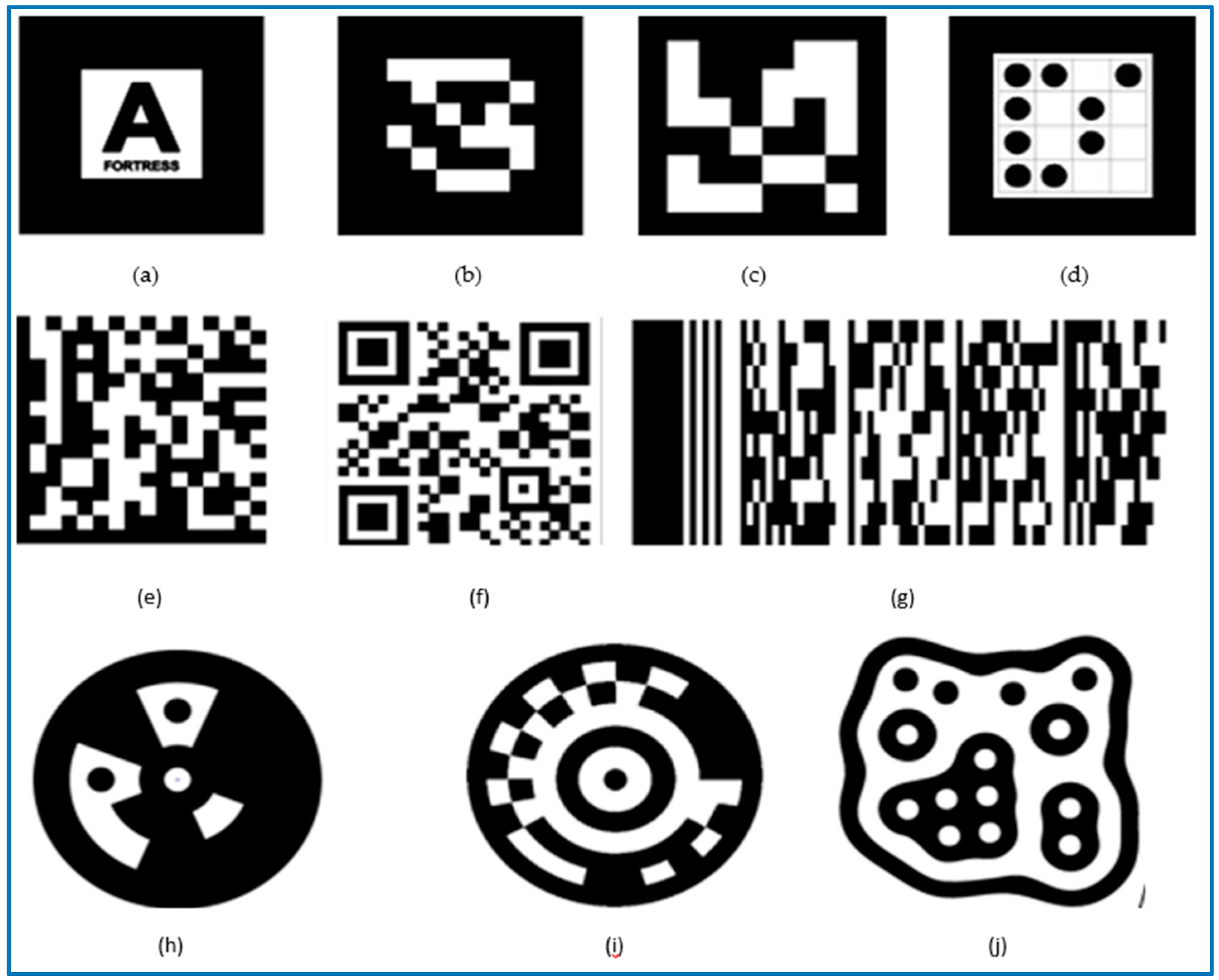
Figure 7.
IR marker for weather forecasting [46].
Figure 7.
IR marker for weather forecasting [46].

Figure 8.
The basic parameters of camera pose estimation [47].
Figure 8.
The basic parameters of camera pose estimation [47].


Table 1.
Comparison between display methods for AR broadcasting.
| Display Methods | Monitor-Based | HMD | Projector | |
|---|---|---|---|---|
| Video-Based | Optical-Based | |||
| Devices | TV screens, Tablet monitor, etc. | Glass-shaped Screen | Optical Combiner | Projector |
| Image Quality | High | Normal | High | Low |
| FOV | Limited | Wide | Wide | Wide |
| No. of viewer | Single | Single | Single | Multiple |
| Advantages | Powerful, Widespread, relatively mature | Portable; Full visualization; Immersive experience | Natural perception of the real-world; Immersive and realistic experience | Multi-views; Appearance change of object; No need for external devices; No program accidents |
| Limitations | Limited view, Limited immersive experience | High computing cost; Need wearable devices; Unnatural view | High computing cost; Need wearable devices; Technical immature | Technical immature; Relatively low quality |
Table 2.
General Sensors.
| Vision Sensor | Laser | IMU | Hybrid Sensor | ||||||
|---|---|---|---|---|---|---|---|---|---|
| Sensor Type | Monocular | Binocular | Omni-directional | 2D Laser | 3D Laser | Camera + Laser | Camera + IMU | ||
| 2D laser | 3D laser | ||||||||
| Sensitivity | Vision | Vision | Vision | Light | Light | Friction | Vision + Light | Vision + Light | Vision + Friction |
| Accuracy | Less Accurate | Accurate | Less-Accurate | Accurate | Less-Accurate | Less-Accurate | Accurate | Less-Accurate | Accurate |
| Flexibility | High | High | High | High | Low | High | High | Low | High |
| DOF | 3/6 DOF | 3/6 DOF | 3/6 DOF | 3 DOF | 6 DOF | 6 DOF | 6 DOF | 6 DOF | 6 DOF |
| FOV | High | High | High | High | Low | High | High | Low | High |
| Price | Low | Low | High | Low | High | Low | Low | High | Low |
© 2017 by the authors. Licensee MDPI, Basel, Switzerland. This article is an open access article distributed under the terms and conditions of the Creative Commons Attribution (CC BY) license (http://creativecommons.org/licenses/by/4.0/).
Share and Cite
MDPI and ACS Style
Yan, D.; Hu, H. Application of Augmented Reality and Robotic Technology in Broadcasting: A Survey. Robotics 2017, 6, 18. https://doi.org/10.3390/robotics6030018
AMA Style
Yan D, Hu H. Application of Augmented Reality and Robotic Technology in Broadcasting: A Survey. Robotics. 2017; 6(3):18. https://doi.org/10.3390/robotics6030018
Chicago/Turabian StyleYan, Dingtian, and Huosheng Hu. 2017. "Application of Augmented Reality and Robotic Technology in Broadcasting: A Survey" Robotics 6, no. 3: 18. https://doi.org/10.3390/robotics6030018
Note that from the first issue of 2016, this journal uses article numbers instead of page numbers. See further details here.