Design, Kinematics and Controlling a Novel Soft Robot Arm with Parallel Motion


Abstract
1. Introduction
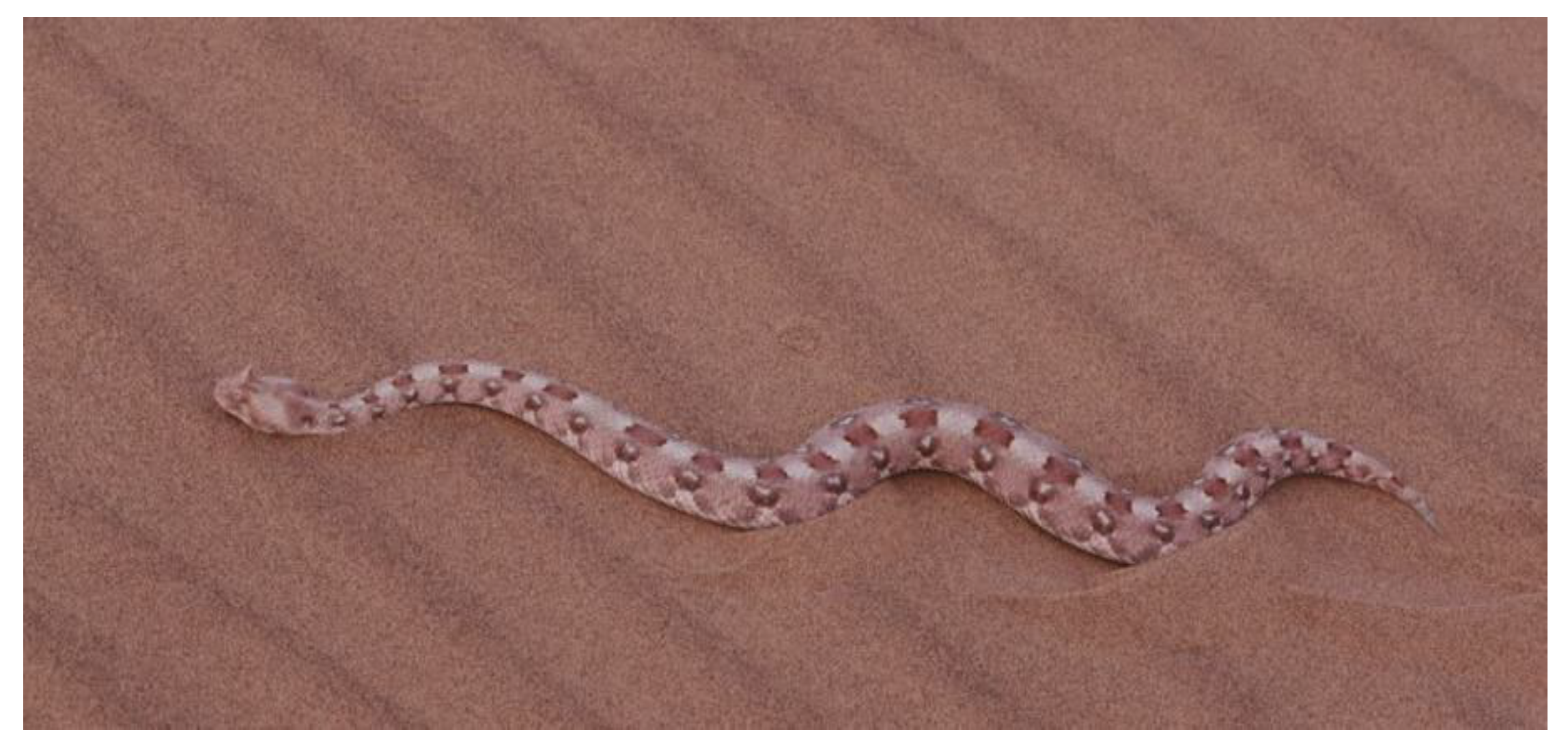
2. Snake Motion
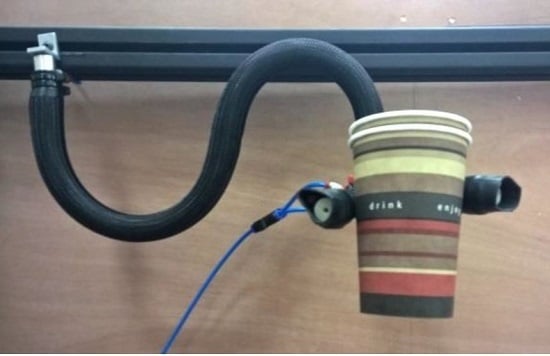
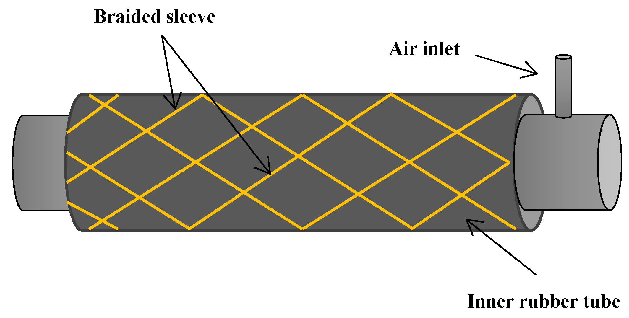
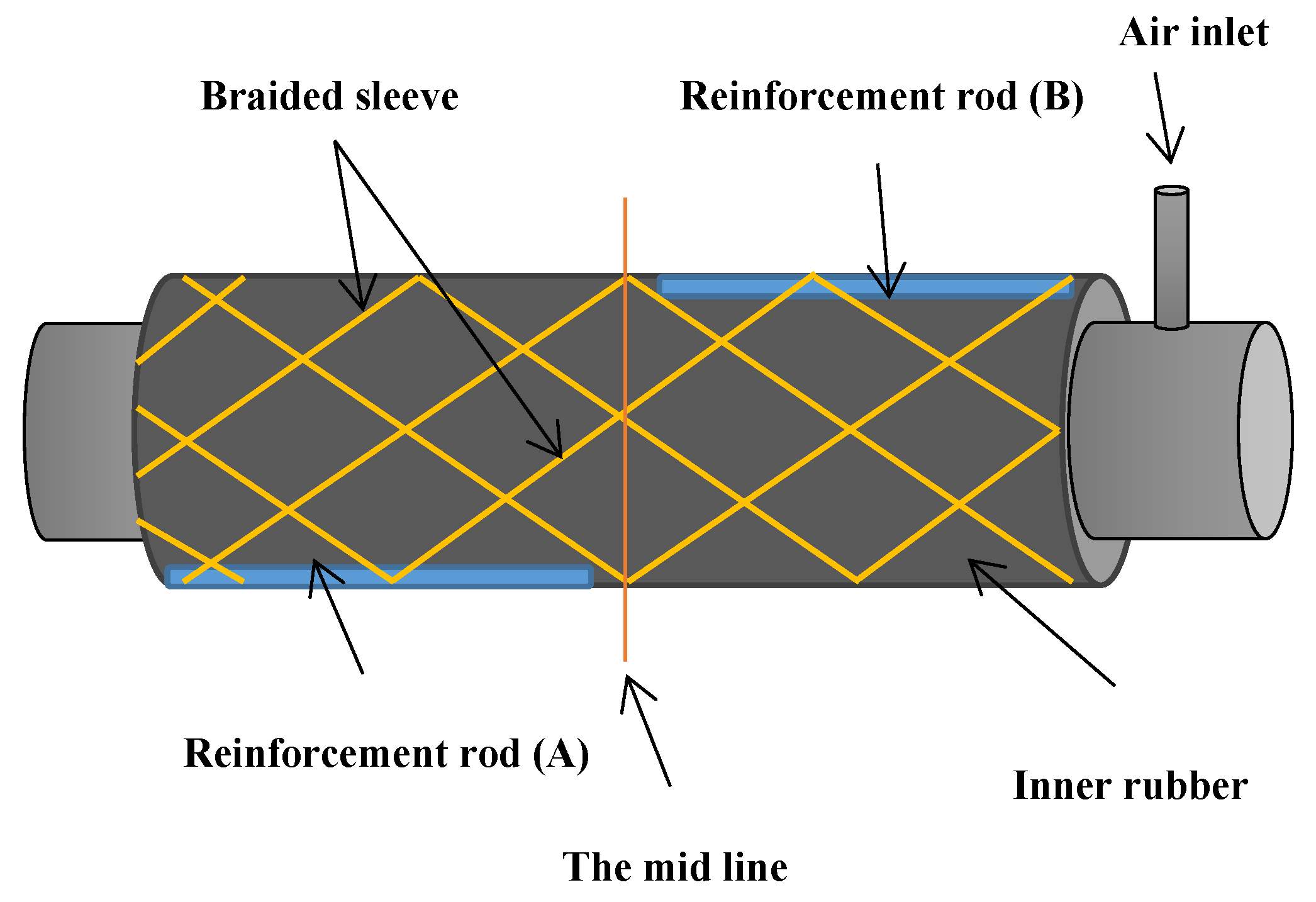
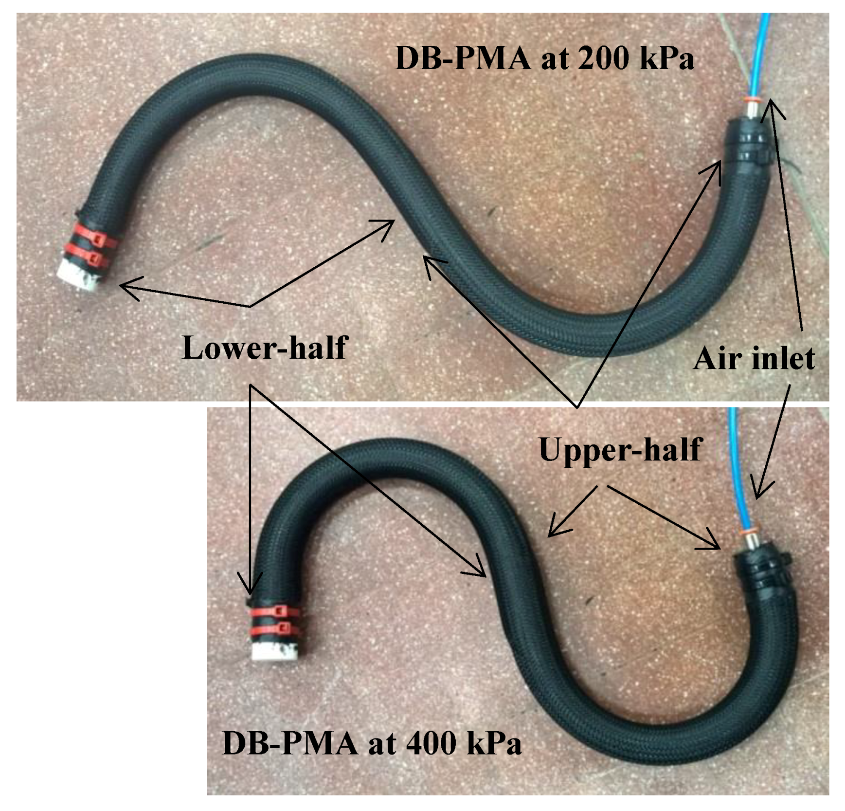
3. Structure of the Double-Bend Actuator
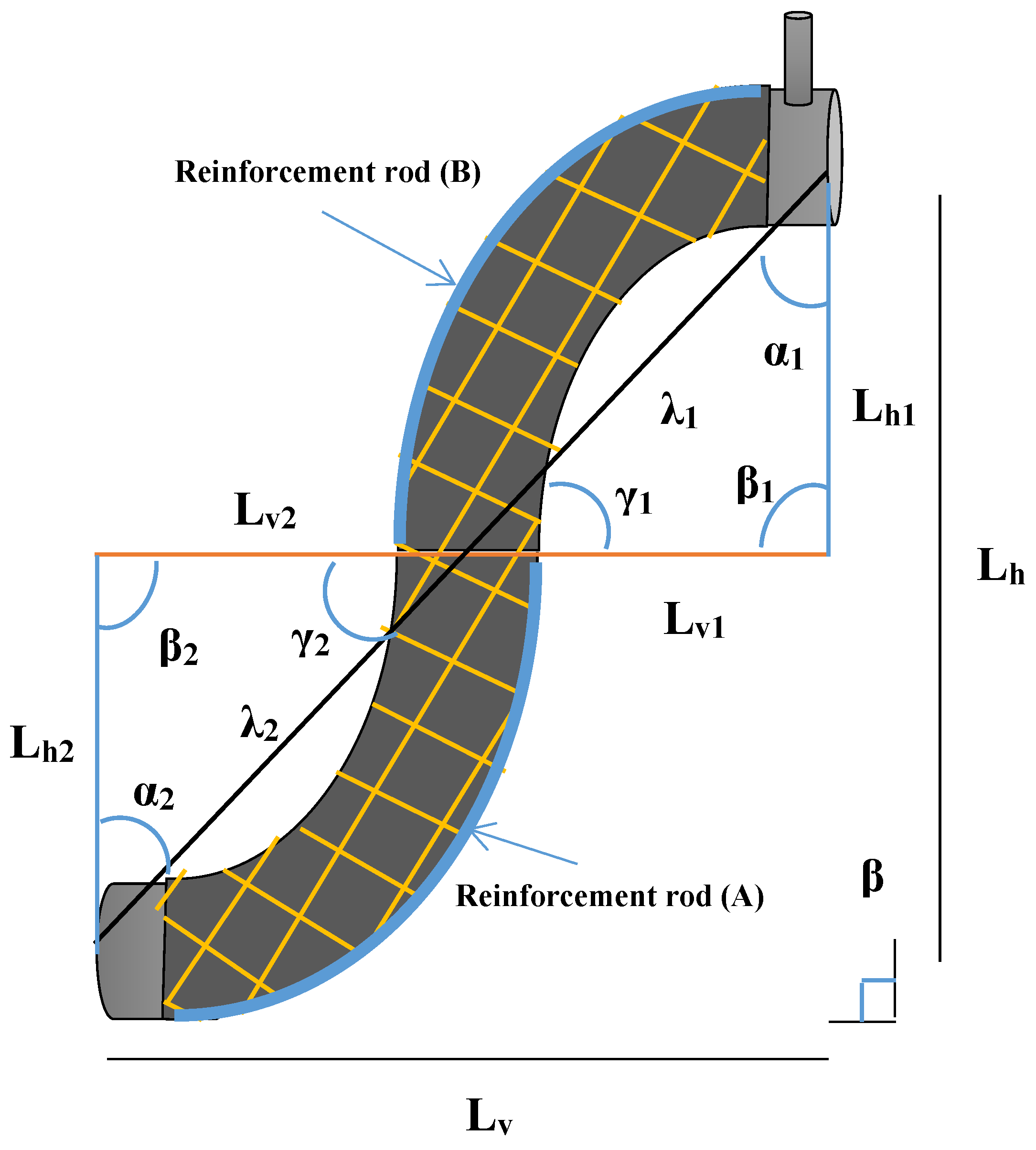
4. Kinematics of the DB-PMA
4.1. Relaxed Condition
4.2. Pressurised Condition
4.3. Special Condition1
4.4. Special Condition2
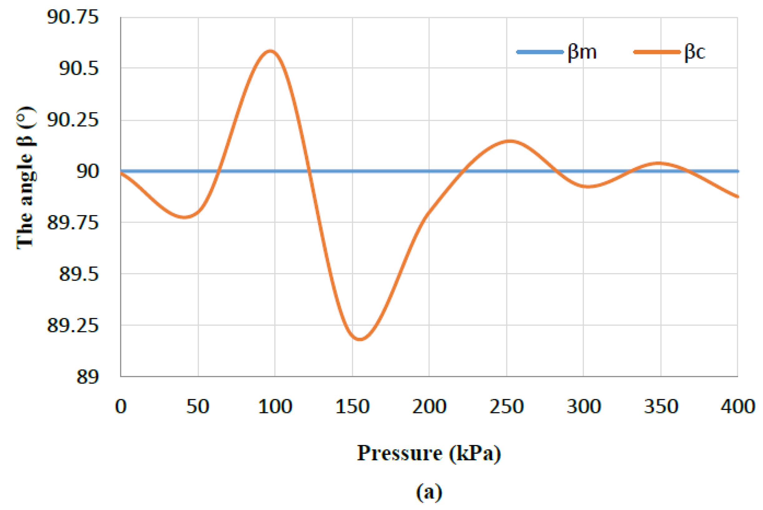
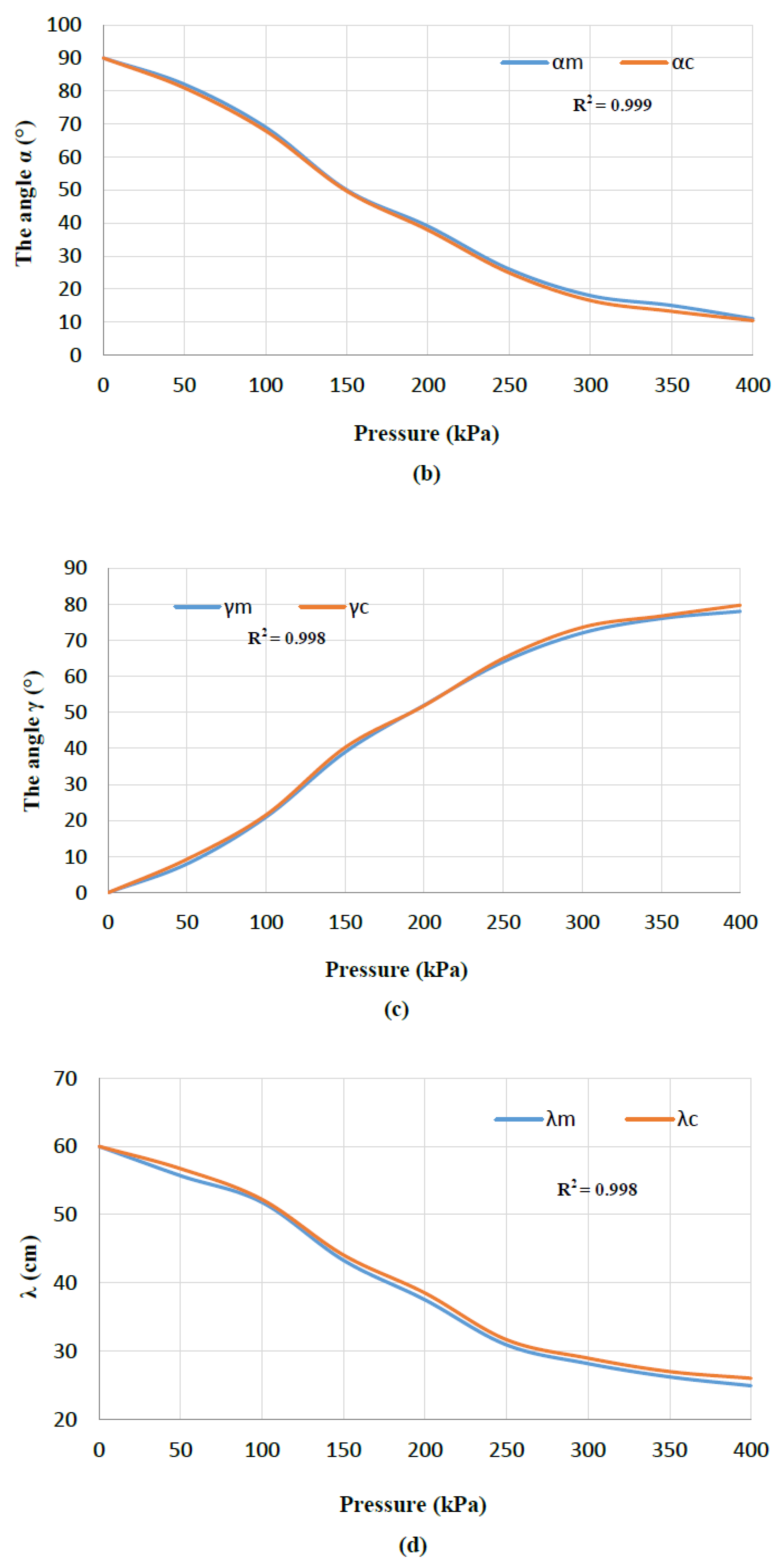
5. Experiments and Validations
6. Horizontal Moving Soft Robot Arm
7. Conclusions
Author Contributions
Acknowledgments
Conflicts of Interest
References
- Fong, T.; Nourbakhsh, I.; Dautenhahn, K. A survey of socially interactive robots. Robot. Autom. Syst. 2003, 42, 143–166. [Google Scholar] [CrossRef]
- Furuta, T.; Tawara, T.; Okumura, Y.; Shimizu, M.; Tomiyama, K. Design and construction of a series of compact humanoid robots and development of biped walk control strategies. Robot. Autom. Syst. 2001, 37, 81–100. [Google Scholar] [CrossRef]
- Gouaillier, D.; Hugel, V.; Blazevic, P.; Kilner, C.; Monceaux, J.; Lafourcade, P.; Maisonnier, B. Mechatronic design of NAO humanoid. In Proceedings of the IEEE International Conference on Robotics and Automation, ICRA’09, Kobe, Japan, 12–17 May 2009. [Google Scholar]
- Kaneko, K.; Kanehiro, F.; Kajita, S.; Yokoyama, K.; Akachi, K.; Kawasaki, T.; Isozumi, T. Design of prototype humanoid robotics platform for HRP. In Proceedings of the IEEE/RSJ International Conference on Intelligent Robots and Systems, Lausanne, Switzerland, 30 September–4 October 2002. [Google Scholar]
- Leite, I.; Martinho, C.; Paiva, A. Social robots for long-term interaction: A survey. Int. J. Soc. Rob. 2013, 5, 291–308. [Google Scholar] [CrossRef]
- Park, I.-W.; Kim, J.-Y.; Lee, J.; Oh, J.-H. Mechanical design of humanoid robot platform KHR-3 (KAIST humanoid robot 3: HUBO). In Proceedings of the 2005 5th IEEE-RAS International Conference on Humanoid Robots, Tsukuba, Japan, 5 December 2005. [Google Scholar]
- Chou, C.-P.; Hannaford, B. Measurement and modeling of McKibben pneumatic artificial muscles. IEEE Trans. Robot. Autom. 1996, 12, 90–102. [Google Scholar] [CrossRef]
- Tondu, B.; Lopez, P. Modeling and control of McKibben artificial muscle robot actuators. IEEE Control Syst. 2000, 20, 15–38. [Google Scholar] [CrossRef]
- Davis, S.; Tsagarakis, N.; Canderle, J.; Caldwell, D.G. Enhanced modelling and performance in braided pneumatic muscle actuators. Int. J. Rob. Res. 2003, 22, 213–227. [Google Scholar] [CrossRef]
- Szepe, T. Accurate force function approximation for pneumatic artificial muscles. In Proceedings of the 2011 3rd IEEE International Symposium on Logistics and Industrial Informatics (LINDI), Budapest, Hungary, 25–27 August 2011. [Google Scholar]
- Ranjan, R.; Upadhyay, P.; Kumar, A.; Dhyani, P. Theoretical and Experimental Modeling of Air Muscle. Int. J. Emerg. Technol. Adv. Eng. 2012, 2, 112–119. [Google Scholar]
- Al-Ibadi, A.; Nefti-Meziani, S.; Davis, S. Valuable experimental model of contraction pneumatic muscle actuator. In Proceedings of the 2016 21st International Conference on Methods and Models in Automation and Robotics (MMAR), Miedzyzdroje, Poland, 29 August–1 September 2016. [Google Scholar]
- Al-Ibadi, A.; Nefti-Meziani, S.; Davis, S. Efficient structure-based models for the McKibben contraction pneumatic muscle actuator: The full description of the behaviour of the contraction PMA. Actuators 2017, 6, 32. [Google Scholar] [CrossRef]
- Doumit, M.; Fahim, A.; Munro, M. Analytical modeling and experimental validation of the braided pneumatic muscle. IEEE Trans. Robot. 2009, 25, 1282–1291. [Google Scholar] [CrossRef]
- Kelasidi, E.; Andrikopoulos, G.; Nikolakopoulos, G.; Manesis, S. A survey on pneumatic muscle actuators modeling. In Proceedings of the 2011 IEEE International Symposium on Industrial Electronics (ISIE), Gdansk, Poland, 27–30 June 2011. [Google Scholar]
- Al-Ibadi, A.; Nefti-Meziani, S.; Davis, S. Novel models for the extension pneumatic muscle actuator performances. In Proceedings of the 2017 23rd International Conference on Automation and Computing (ICAC), Huddersfield, UK, 7–8 September 2017. [Google Scholar]
- Ilievski, F.; Mazzeo, A.D.; Shepherd, R.F.; Chen, X.; Whitesides, G.M. Soft robotics for chemists. Angew. Chem. 2011, 123, 1930–1935. [Google Scholar] [CrossRef]
- Deimel, R.; Brock, O. A compliant hand based on a novel pneumatic actuator. In Proceedings of the 2013 IEEE International Conference on Robotics and Automation (ICRA), Karlsruhe, Germany, 6–10 May 2013. [Google Scholar]
- Al-Ibadi, A.; Nefti-Meziani, S.; Davis, S. Cooperative project by self-bending continuum arms. In Proceedings of the 2017 23rd International Conference on Automation and Computing (ICAC), Huddersfield, UK, 7–8 September 2017. [Google Scholar]
- Al-Fahaam, H.; Davis, S.; Nefti-Meziani, S. The design and mathematical modelling of novel extensor bending pneumatic artificial muscles (EBPAMs) for soft exoskeletons. Robot. Autom. Syst. 2018, 99, 63–74. [Google Scholar] [CrossRef]
- Faudzi, A.A.M.; Razif, M.R.M.; Nordin, I.N.A.M.; Suzumori, K.; Wakimoto, S.; Hirooka, D. Development of bending soft actuator with different braided angles. In Proceedings of the 2012 IEEE/ASME International Conference on Advanced Intelligent Mechatronics (AIM), Kachsiung, Taiwan, 11–14 July 2012. [Google Scholar]
- Erkmen, I.; Erkmen, A.M.; Matsuno, F.; Chatterjee, R.; Kamegawa, T. Snake robots to the rescue! IEEE Robot. Autom. Mag. 2002, 9, 17–25. [Google Scholar] [CrossRef]
- Transeth, A.A.; Pettersen, K.Y.; Liljebäck, P. A survey on snake robot modeling and locomotion. Robotica 2009, 27, 999–1015. [Google Scholar] [CrossRef]
- Hopkins, J.K.; Spranklin, B.W.; Gupta, S.K. A survey of snake-inspired robot designs. Bioinspir. Biomim. 2009, 4, 021001. [Google Scholar] [CrossRef] [PubMed]
- Shan, Y.; Koren, Y. Design and motion planning of a mechanical snake. IEEE Trans. Syst. Man Cybern. 1993, 23, 1091–1100. [Google Scholar] [CrossRef]
- Yamakita, M.; Yamada, T.; Tanaka, K. Control of snake like robot for locomotion and manipulation. In Proceedings of the 2nd International Symposium on Adaptive Motion of Animals and Machines, WeP-III, Kyoto, Japan, 4–8 March 2003. [Google Scholar]
- Wright, C.; Buchan, A.; Brown, B.; Geist, J.; Schwerin, M.; Rollinson, D.; Choset, H. Design and architecture of the unified modular snake robot. In Proceedings of the 2012 IEEE International Conference on Robotics and Automation (ICRA), Saint Paul, MN, USA, 14–18 May 2012. [Google Scholar]
- Wright, C.; Johnson, A.; Peck, A.; McCord, Z.; Naaktgeboren, A.; Gianfortoni, P.; Choset, H. Design of a modular snake robot. In Proceedings of the IEEE/RSJ International Conference on Intelligent Robots and Systems, IROS 2007, San Diego, CA, USA, 29 October–2 November 2007. [Google Scholar]
- Hirose, S.; Yamada, H. Snake-like robots [tutorial]. IEEE Robot. Autom. Mag. 2009, 16, 88–98. [Google Scholar] [CrossRef]


| Length of the Actuator and Reinforcement Rod (cm) | Maximum Bending Angle |
|---|---|
| 10 | 25° |
| 20 | 125° |
| 30 | 213° |
© 2018 by the authors. Licensee MDPI, Basel, Switzerland. This article is an open access article distributed under the terms and conditions of the Creative Commons Attribution (CC BY) license (http://creativecommons.org/licenses/by/4.0/).
Share and Cite
Al-Ibadi, A.; Nefti-Meziani, S.; Davis, S. Design, Kinematics and Controlling a Novel Soft Robot Arm with Parallel Motion. Robotics 2018, 7, 19. https://doi.org/10.3390/robotics7020019
Al-Ibadi A, Nefti-Meziani S, Davis S. Design, Kinematics and Controlling a Novel Soft Robot Arm with Parallel Motion. Robotics. 2018; 7(2):19. https://doi.org/10.3390/robotics7020019
Chicago/Turabian StyleAl-Ibadi, Alaa, Samia Nefti-Meziani, and Steve Davis. 2018. "Design, Kinematics and Controlling a Novel Soft Robot Arm with Parallel Motion" Robotics 7, no. 2: 19. https://doi.org/10.3390/robotics7020019
APA StyleAl-Ibadi, A., Nefti-Meziani, S., & Davis, S. (2018). Design, Kinematics and Controlling a Novel Soft Robot Arm with Parallel Motion. Robotics, 7(2), 19. https://doi.org/10.3390/robotics7020019