A Structural Optimisation Method for a Soft Pneumatic Actuator


1
School of Mechanical, Materials, Mechatronic and Biomedical Engineering, University of Wollongong, Wollongong 2522 NSW, Australia
2
ARC Centre of Excellence for Electromaterials Science, University of Wollongong, Wollongong 2522 NSW, Australia
*
Author to whom correspondence should be addressed.
Robotics 2018, 7(2), 24; https://doi.org/10.3390/robotics7020024
Submission received: 12 April 2018
/
Revised: 21 May 2018
/
Accepted: 30 May 2018
/
Published: 1 June 2018
(This article belongs to the Special Issue Mechanics, Control, Design, Conceptualization and Fabrication of Soft Robotic Systems)
Abstract
:This study aims to investigate the effects of various design parameters on the actuation performance of a pneumatic network actuator (PNA), optimise its structure using the finite element method (FEM), and subsequently quantify the performance of the resulting actuator topology experimentally. The effects of the structural parameters, including the operation pressure, the wall thickness and the gap between the chambers, bottom layer thickness, and the geometry of the channel cross section, on the deformation and bending angle of the actuator were evaluated to optimise the performance of the pneumatic actuator. A Global Analysis of Variance (ANOVA) was performed to investigate how the variables affect the mechanical output of the actuator and, thus, the significance of variables affecting the deformation (and bending angle) of the pneumatic actuator was identified. After the parameter optimisation, a pneumatic channel with a 4.5 mm bottom layer thickness, 1.5 mm wall thickness, and 1.5 mm gap between sequential chambers is recommended to perform optimised bending motion for the pneumatic network actuator. The optimised FE model results were verified experimentally. This design optimisation method based on the FEM and ANOVA analysis can be extended to the topology optimisation of other soft actuators.
1. Introduction
The emerging field of soft robotics aims to establish robotic systems primarily made of soft materials (E < 100 MPa) to perform complicated locomotion in various environments and to interact with and adapt to their physical environments in a safer and better way than their predecessors (i.e., conventional robotic systems made of hard materials) without requiring advanced feedback control techniques. The performance of the soft robotic systems strongly depends on the performance of their actuators. Soft actuators are expected to be soft and compliant like natural muscles [1,2,3,4], which cannot be provided by traditional actuators such as electric motors. To develop an artificial muscle that has a similar function to natural muscle is one of the main challenges in soft robotics.
Pneumatic actuators are widely used in robotics and automation. They are cheap, lightweight and safe during human–robot interactions, and can deliver high power densities with a remarkable mechanical output [5,6]. Pneumatic actuators offer better soft actuation features than do conventional actuators due to their convenience and simplicity. With the recent progress in soft and processable smart materials, soft actuation concepts that make use of pneumatic networks in a slender body have been proposed [5,6,7,8,9]. Such pneumatic actuators can generate bending and linear movements, offering high potential to be employed in soft robotics and medical applications due to their inherent compliance and safety. A pneumatic actuation methodology based on PneuNets’ concept can generate a simple bending motion with only one pressure source [10]. The PneuNets geometry and mechanics have been investigated using a simple theoretical model [11]. This model has the potential to be used as a design principle for designing soft pneumatic autonomous actuators. The effect of material properties and chamber geometry on the performance of the actuator is described. The movements of this soft actuator are generated by pressurising the internal PneuNets, and the configuration of the actuator is determined by the structure of the channels. Air is selected as the power source for its unique features, such as compressibility, ease of storage, low viscosity, and ability to provide rapid actuation process. The same methodology has been used in a multigait quadrupedal soft robot [12]. These robots, like some animals (such as squids, starfish, and worms), have no rigid internal skeletons. The soft robot described in [13] combines microfluidics and the PneuNets concept. The pneumatic systems are used for activation and the colour-filled microfluidics channels in the thin silicone surface are used for camouflage. Various applications using these kinds of actuators have been reported [7,14,15]. A large pneumatically actuated soft robot (0.65 m in length) with an embedded controller, battery, and miniature compressors was developed in [16]. This soft robot can carry its power system and adapts to various environments. The main difference between the large robot and the PneuNets robots is that there is a small gap between the adjacent channels. It can provide a higher work output and rapid movement. Mosadegh et al. [5] made some improvements in the PneuNets actuators and developed a rapid response actuator made of silicone rubber. They compared the slow and rapid actuation using pneumatic networks and showed a novel pattern of actuation which was sufficiently durable. Several similar actuation mechanisms that can perform a bending movement have been reported [17,18,19,20,21,22].
The soft pneumatic network actuators that can generate significant deflection have considerable potential for medical applications, especially for prosthetic and rehabilitation devices. However, the bending performance of these kinds of actuators strongly depends on the design parameters of the channels. Therefore, there is a need for an efficient method to optimise the bending angle of the pneumatic network actuators. The aim of this study is to optimise the structure of the pneumatic network actuator. Different designs of the pneumatic channels are used to quantify the effects of the critical design parameters. The overall soft actuator design is optimised using the finite element method to fulfil the required bending performance. A methodology based on statistical analysis (ANOVA) is employed to optimise the performance of a pneumatic actuator proposed for use in soft robotic applications. Section 2 presents the parametric investigation of the pneumatic actuator to obtain an optimised structure that can generate large bending angles. In Section 3, we describe the fabrication method. The comparison of the experimental and simulation results is presented in Section 4. Conclusions and future work are described in Section 5.
2. Parametric Investigation for Structure Optimisation of the Actuator
The finite element analysis method is widely used in design optimisation. The objective of this section is (i) to develop a finite element model that can predict the mechanical output or bending performance of the pneumatic actuator; (ii) to investigate the effects of primary parameters; and (iii) to optimise the structure of the actuator, which is in a one-end fixed, other-end free configuration—like a cantilever beam. The FE modelling was conducted in ANSYS Workbench using Static Structural Analysis. The left surface of the soft actuator was fixed, acting as the fixed boundary, and the pressure inputs were applied equally on the inner surfaces of each chamber. Large deformation effects were taken into account in the finite element model.
2.1. The Structure of the Actuator
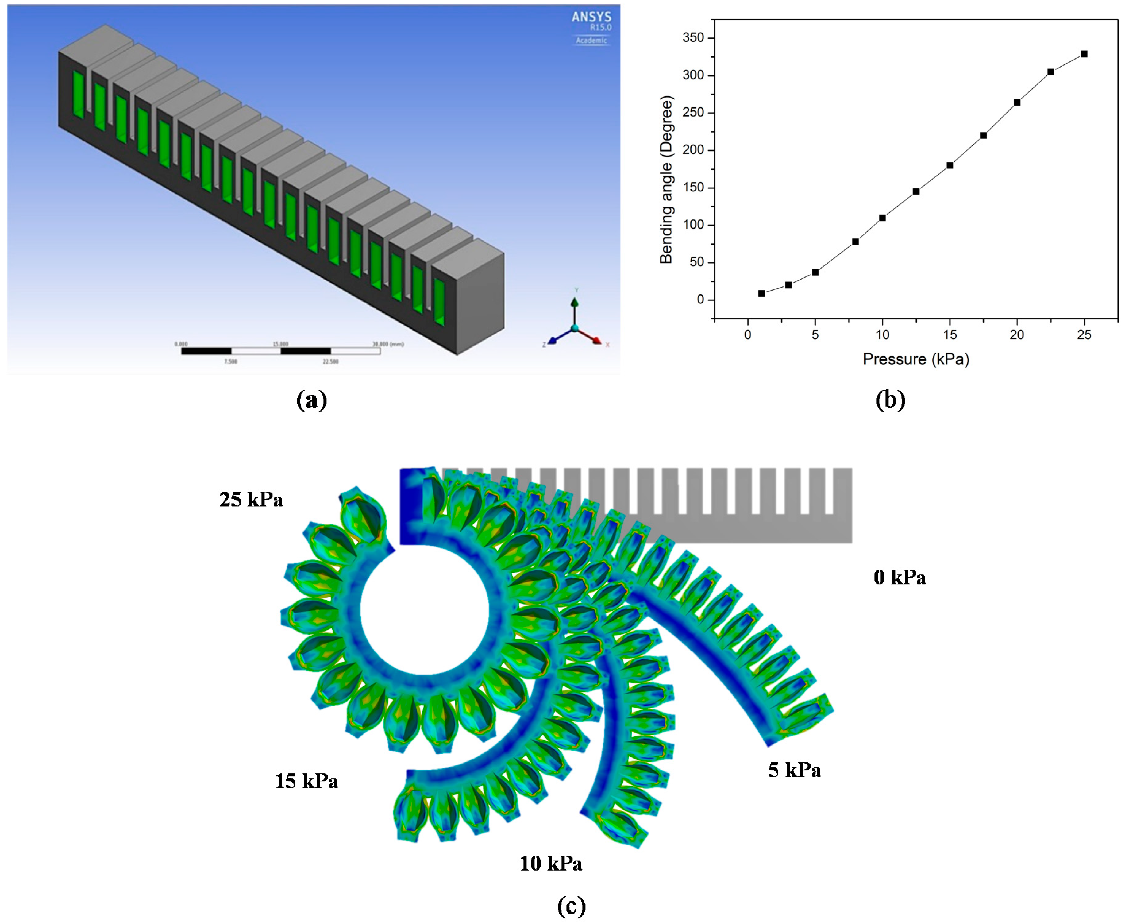
The pneumatic actuator described in this study consists of a series of channels arranged in a row, also known as a pneumatic network actuator [5,6,9]. When the actuator is inflated, the channels will expand, causing the actuator to deform in the longitudinal direction. The actuator consists of two layers—the upper active layer and the passive bottom layer—as shown in Figure 1a. When compressed air is inputted to the channels, the active layer will deform, as shown in Figure 1c. Upon increasing the input pressure, a significant increase in the deformation and bending angle is observed. There is an approximately linear relationship between the pressure and bending angle, as revealed in Figure 1b, under this pressure range.
2.2. Material Selection
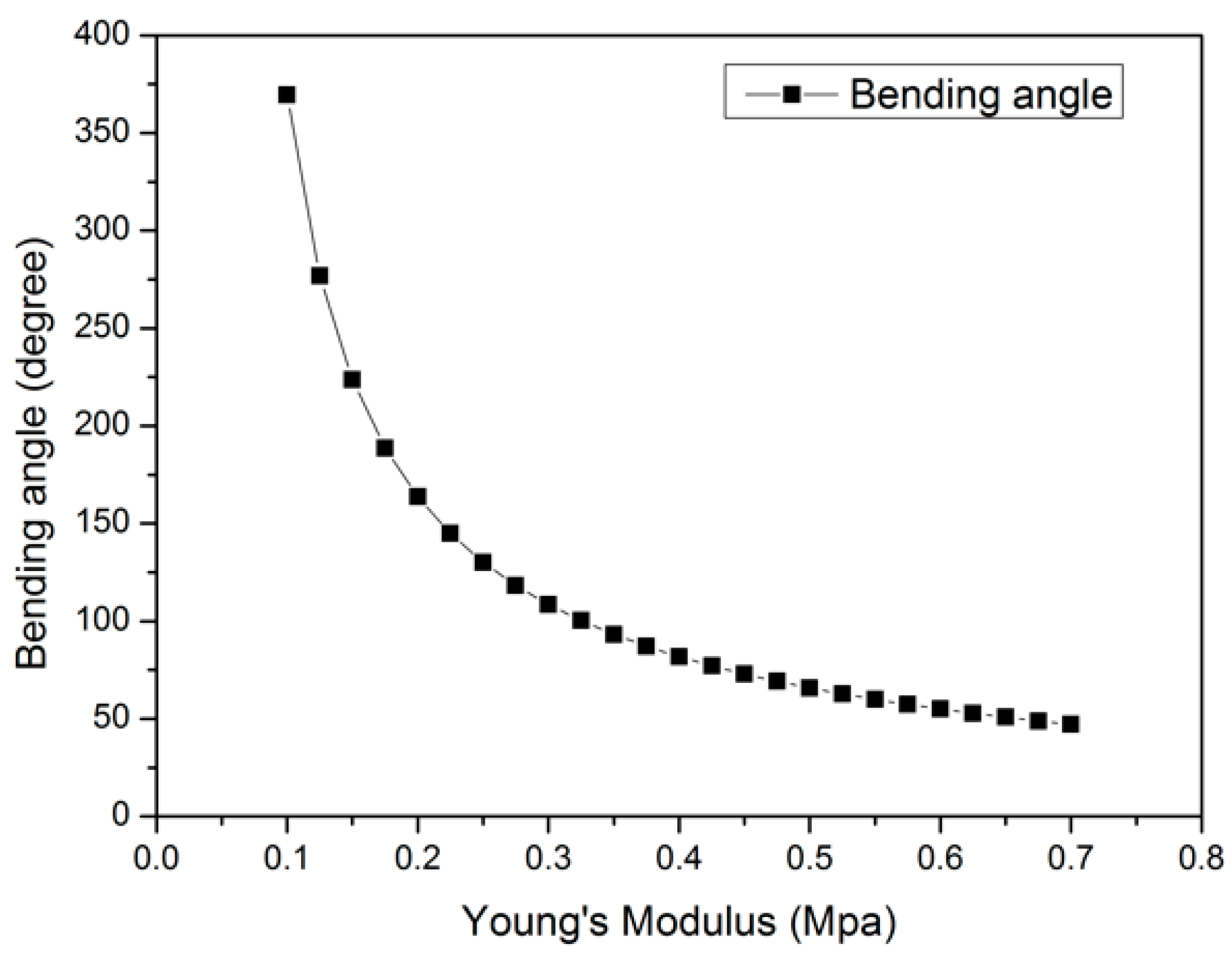
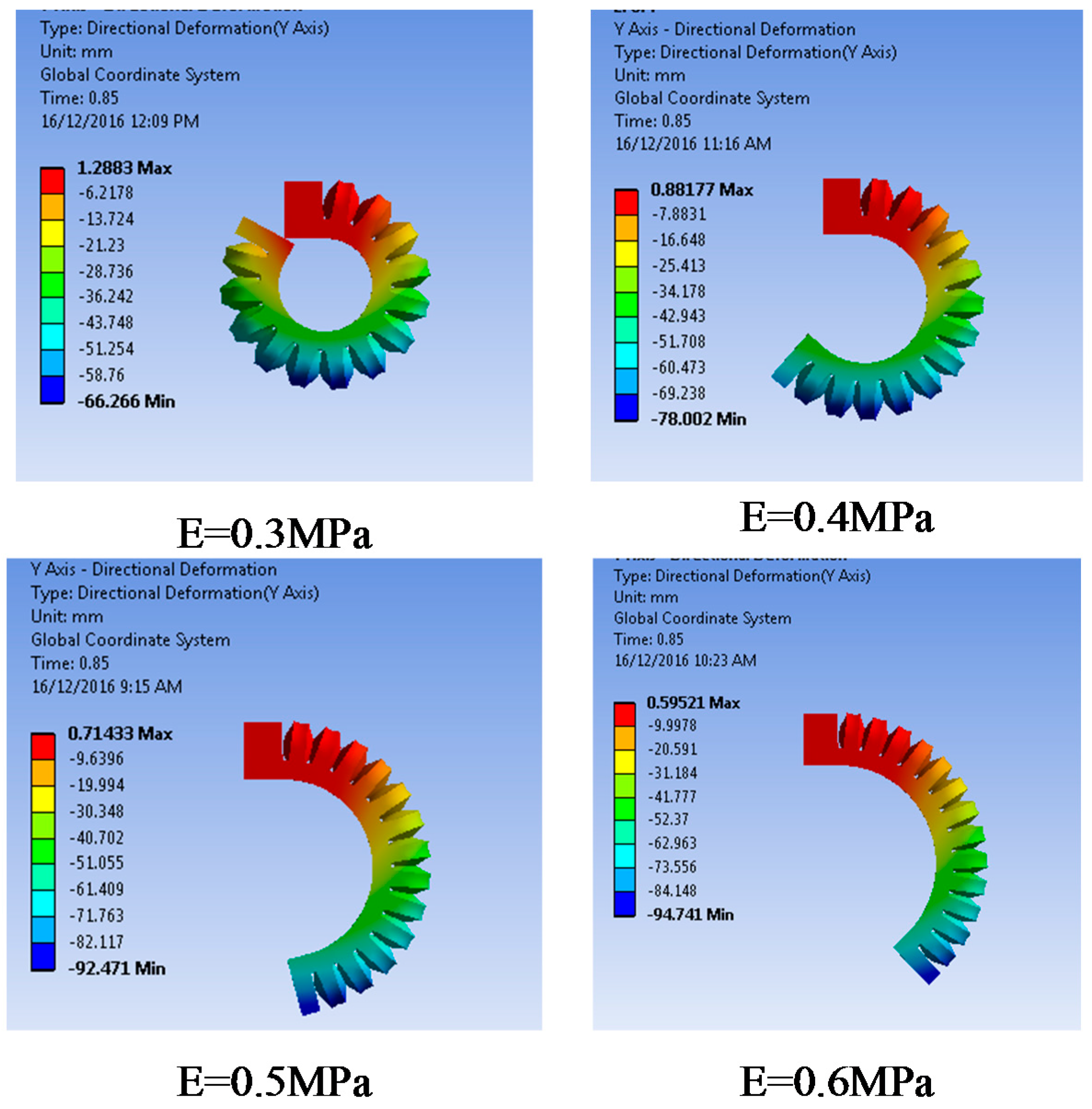
Silicone rubber has been chosen as the actuator material for a number of reasons. This material is inexpensive, can be moulded into a variety of shapes with a low actuation pressure or stress, and it exhibits the properties desirable for the actuator. Figure 2 shows that with an increase in Young’s modulus, the bending deformation will decrease. As shown in Figure 2, when the Young’s modulus is 0.1 MPa, the deformation is twice that at 0.2 MPa; this then turns into an exponentially decreasing trend. There is an inverse relationship between the Young’s modulus of the materials and the deformation of the actuator under high pressures.
The material should have a reasonable stiffness to provide enough bending angle and blocking force to perform grasping tasks for soft robotic gripper applications. In addition, the bursting of pneumatic channels should be considered when selecting materials. Figure 3 illustrates that the actuator made from various silicone rubbers that have different moduli of elasticity generate different bending angles under the same test pressure (20 kPa).
There are several methods to test the mechanical measurement of soft metrical characterisation. In [23], the measurement of the three elastomers Sylgard 184, Smooth-Sil 950, and Ecoflex 00-30 was demonstrated. In this study, the silicone rubber M4601 is used as the test material. Due to the composite structure of the actuators with pneumatic networks inside, the effective modulus of elasticity of the actuator is different from the specific modulus of elasticity of the material. The effective modulus of elasticity was adopted in the simulations of the actuator. M4601 has an effective modulus of elasticity of 386.66 kPa, which was proposed and identified in [24] using numerical and experimental results, and some physical properties of the material are listed in Table 1. The modulus of elasticity for hyperelastic materials is not constant, and the movement of the actuator is nonlinear.
2.3. Analysis of Variance (ANOVA)
Several parameters of the pneumatic actuator are studied in the finite element model. To reduce the simulation and experimental efforts to a manageable size, only the bottom layer thickness, the gap between the adjacent channels, the wall thickness of the channels, and the shape of the cross section are considered for the design optimisation of the proposed actuator concept. To examine how the actuator geometry affects the actuator bending angle (and strain), the overall length of 140 mm and width of 20 mm of the actuator are kept constant. The overall volume of 512 m3 and the surface area of each channel are also held constant.
To investigate how the variables affect the deformation of the actuator and which variables affect the deformation significantly, a Global Analysis of Variance (ANOVA) using Minitab 17 was performed. The parameters listed in Table 2 were used in the simulation. The effects of all variables were analysed using the full factorial design module. To reduce the size of the calculation, three groups of simulations were carried out. In this analysis, the bottom layer thickness (4.5–6 mm), wall thickness (1–1.75 mm), and gap sizes (1–1.75 mm), each with four levels, were tested with an input pressure of 20 kPa under the same simulation environment. Sixty-four different parameters considered in the simulation results were used in the analysis. The residual plot for the bending angle shown in Figure 4a illustrates the distribution of the data from the simulation results. A random pattern is also presented in the graph of residual versus case numbers, as shown in Figure 4b, indicating that the ANOVA results are reasonable.
The ANOVA results are summarised in Table 3. The F value represents the mean square error to the residual, which determines the importance of one factor. The P value represents the significance degree. The analysis is performed at 5% significance level, so when P is less than 5%, the parameter has a significant effect on the variable result. The F value of the bottom layer thickness is 332.91; this is the most significant factor which influences the bending angle, followed by the wall thickness and, finally, the gap size.
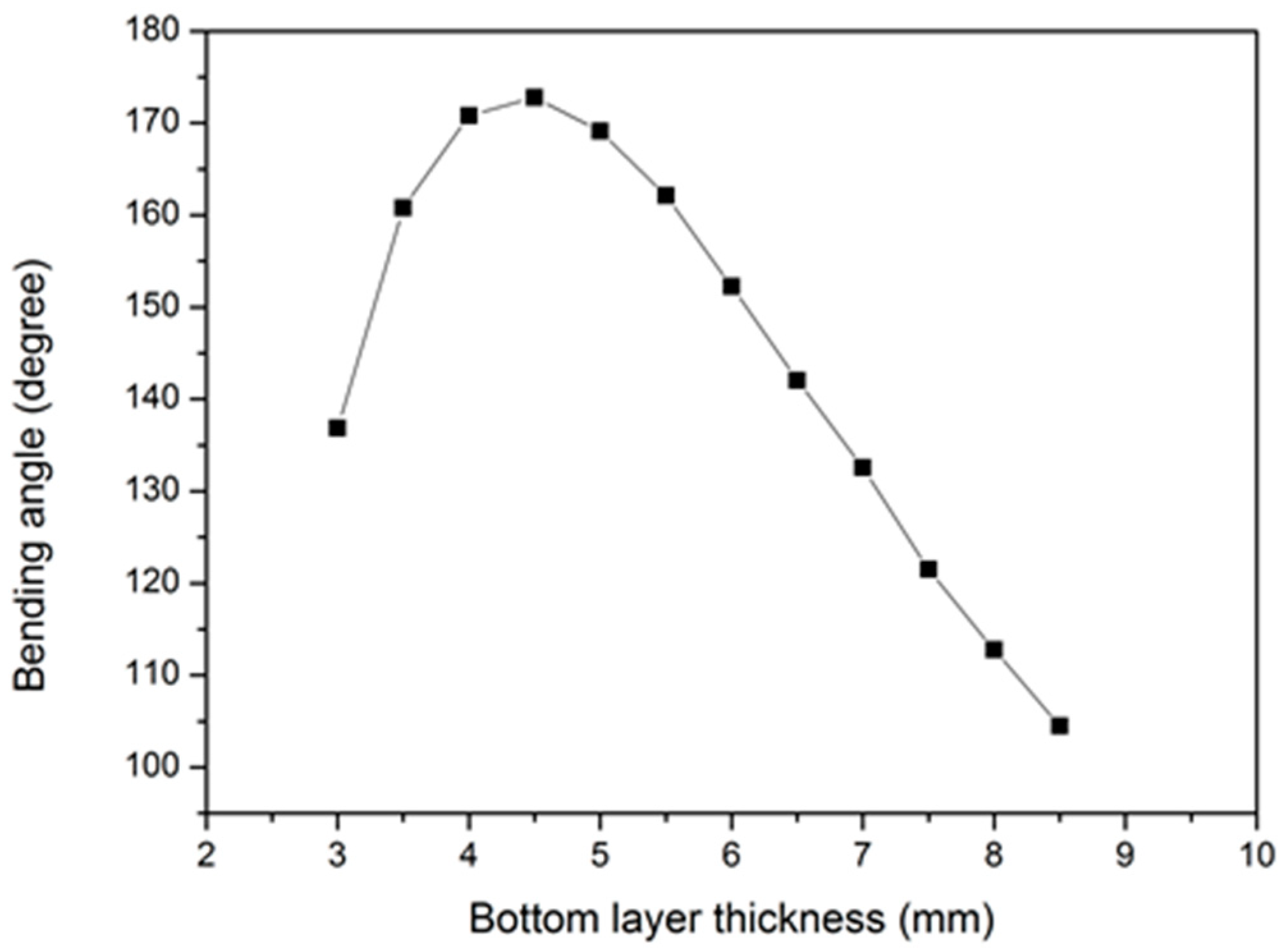
2.4. Effect of Bottom Layer Thickness
The parametric optimisation for the thickness of the unpressurised bottom layer is based on the model shown in Figure 5. M4601 Silicone rubber was used in the experimental work. Its modulus of elasticity was set as E = 0.387 MPa in the simulation results. The other parameters were kept constant, except for the lower layer thickness. The gap size and wall thickness were 1.5 mm, which was constant in this simulation setting. To further investigate the effect of the most significant parameter obtained through the ANOVA results, an extensive value range of bottom layer thickness was adopted. Figure 5 shows that the bending angle follows a parabolic relationship with the bottom layer thickness. For a smaller bottom layer thickness, the bending angle increases when the bottom layer is increased from 3 mm to 4.5 mm. The bending angle reaches the maximum value of approximately 172 degrees for a bottom layer thickness of 4.5 mm. However, the bending angle decreases with the further increase in the bottom layer thickness from 4.5 mm to 8.5 mm. We postulate that this is primarily due to the fact that the area moment of inertia has increased with these values of the bottom layer thickness, creating more resistance to bending than increasing the bending angle. Consequently, if the bottom layer is the only design variable that should be considered, a bottom layer of 4.5 mm that can provide the largest bending angle is the optimised value.
2.5. Effect of Gap between Adjacent Channels
Figure 6 shows the variation of the bending angle with the gap between the adjacent channels, where the bending angle of the actuator shows a decreasing trend with the gap size. A smaller gap can be expected to generate a larger bending angle so that a smaller gap could be used. When 0.5 mm and 1 mm gaps are used, the adjacent channels will touch each other. However, there will not be contact between the adjacent channels when 2 mm gaps are applied. Though the interaction force between the channels can potentially generate larger bending angles, it may also cause damage to the channels. Therefore, to avoid the bursting problem and to achieve a relatively large bending angle, a 1.5 mm gap is more appropriate in this design.
2.6. Effect of Channel Wall Thickness
The second design parameter considered is the wall thickness (the distance between the pneumatic channel and outside surface) of each channel, changing from 1.0 mm to 1.75 mm. Figure 7 presents the effect of the wall thickness on bending angles: when a decrease in the wall thickness occurs, the bending angle becomes larger in a linear fashion.
The whole actuator is in the form of a cantilever beam when it is actuating and generating bending motion. Figure 8 shows the cross section of the actuator chamber, where a, b, a0, b0, t, and w represent the inside dimensions, outside dimensions, bottom layer thickness, and wall thickness, respectively. a, b, and t are kept constant in this analysis to investigate the effect of wall thickness. The deformation of the chamber is caused by the offset e between the centre of pressure (P) and the neutral axis () [22], as shown in Figure 8, and the cantilever will bend towards the neutral axis. The radius of curvature is given by
where R, P, A, E, and I are the radius of the curvature, pressure, area of inside the channel, modulus of elasticity, and area moment of inertia of the deflected beam or actuator, respectively. The change in wall thickness can also result in a change in the area moment of inertia, which will affect the curvature. In this research, R, P, A, and E are all kept constant. Therefore, the radius of curvature is mainly affected by the ratio e/I. The dimensions of the cross section are shown in Figure 8, and the centre of pressure and neutral axis () are given by
The area moment of inertia I about the centroid axis of a cross section is given by
where y is the perpendicular distance from axis x to the element dA. There is a distance between the centroid axes of the outside rectangle and inside rectangle. Therefore, a parallel axis theorem is employed to obtain the moment of inertia of the cross section about its centroid axis. The theorem is given by
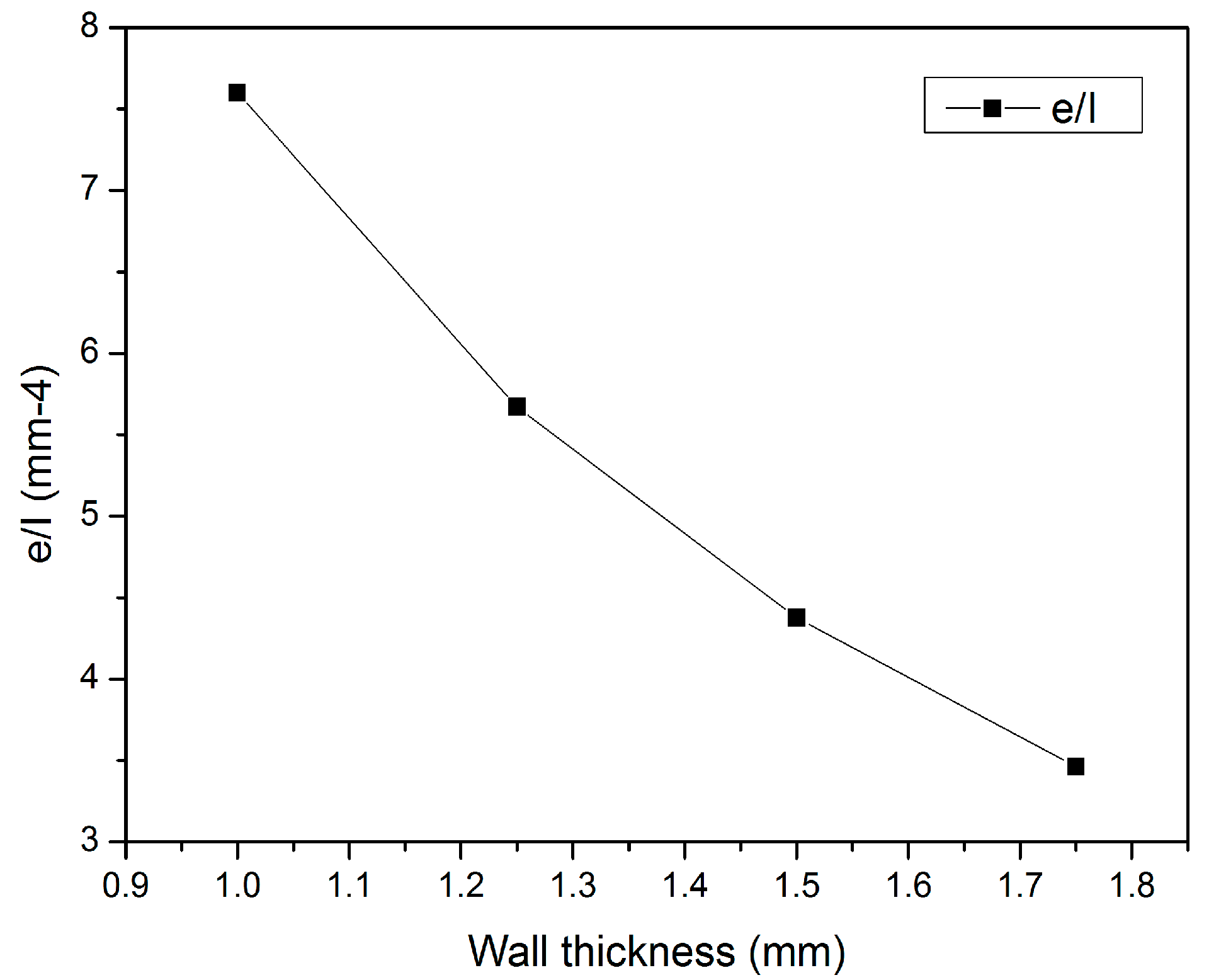
where is the moment of inertia about its own centroid axis and is the moment of inertia about any parallel axis with a distance of d. In the simulations, the wall thickness is varied from 1 mm to 1.75 mm with thickness increments of 0.25 mm. Then, the distance between the centre of pressure and the neutral axis e and area moment of inertia I are calculated. The results are shown in Figure 9; as the wall thickness increases, the e/I ratio becomes smaller, which means that the bending angle becomes smaller. These results agree with the simulation results in Figure 7.
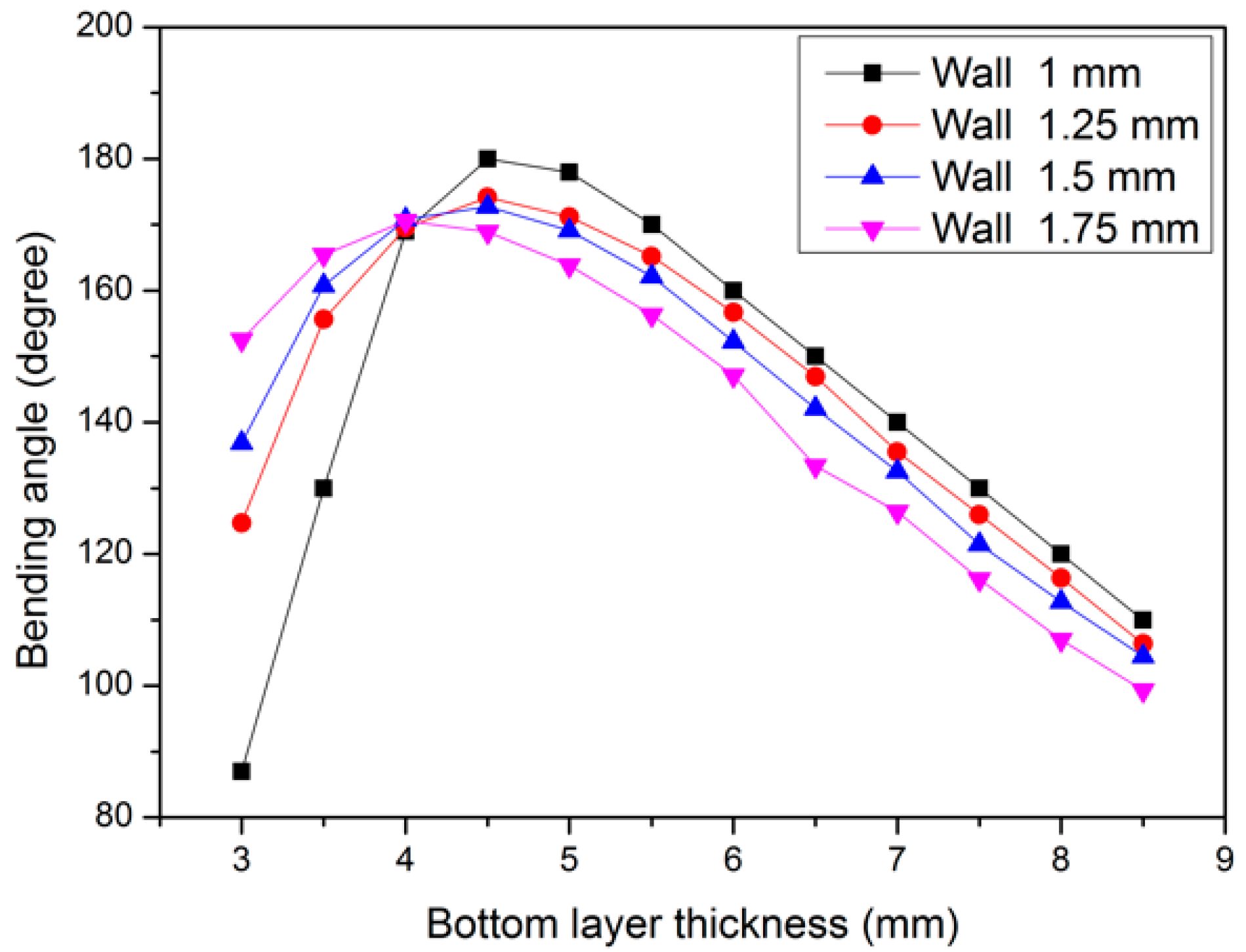
The wall thickness is an important variable since a thin wall will easily rupture whereas a thick wall requires a relatively high pressure to generate the same bending angle. However, when a thin wall thickness is applied, it is relatively easy for the chambers to be damaged. Thus, these two factors should be considered together when choosing the wall thickness. The wall should be thin enough to generate full bending and thick enough to bear the actuation pressure. To select a proper wall thickness, the wall thickness and bottom layer thickness are considered together, as shown in Figure 10. These results indicate that, before the maximum point, the results in Figure 10 are mainly affected by the bottom layer thickness. The bottom layer thickness affects the bending angle more than the wall thickness, which agrees to an acceptable degree with the ANOVA results. However, a 1 mm wall thickness and 4.5 mm bottom layer thickness can be expected to generate the largest bending angle. Since a low-cost 3D printing method is used to fabricate the actuator, the fabrication accuracy and bursting issues should be considered; hence, a 1.5 mm wall thickness is preferred in this design. Based on the analysis of the simulation results and several experimental testing results, 4.5 mm bottom layer thickness, 1.5 mm wall thickness, and 1.5 mm gap size are recommended to be used in the pneumatic actuator design.
2.7. Effect of Cross Section
Figure 11 shows the variation of the bending angle with the channel cross sections that consist of (1) rectangular cross section; (2) honeycomb cross section; (3) half-round cross section; and (4) round cross section, which is illustrated in Figure 11b. Figure 11 shows that the bending angle can be affected by the cross section, while the actuator with round cross section can provide the least bending, and the actuators with rectangular, honeycomb and half-round cross sections can provide similar bending angles under the same input pressure. The volume of the channels is kept constant. The thickness of the bottom layer of 4.5 mm, the wall thickness of 1.5 mm, and a total length of 104 mm are also held constant. However, the volume of the entire structure is different. The bending angle θ is directly proportional to the ratio of the total channel volume (Vc) to the total (i.e., overall) structural volume (Vs). It must be noted that for a pneumatic actuation system based on flexible chambers, the input work is the gauge pressure multiplied by the change in the chamber volume. The pressure is constant for all the cross sections, which leaves the volume change as the primary variable to compare and quantify the bending performance of the various cross sections. Our numerical results show that the ratio of Vc/Vs for the round cross section is the smallest, which makes the actuator with round cross section generate the lowest bending performance (i.e., angle).
When the pressure is below 25 kPa, the bending angle shows a nearly linear relationship with the pressure. When the pressure is over 25 kPa, the adjacent channels will touch and push each other. Due to their interaction forces, the relationship between bending angle and pressure ceases to be linear because a more complicated interaction may occur under higher pressures.
3. Fabrication of the Soft Pneumatic Actuator
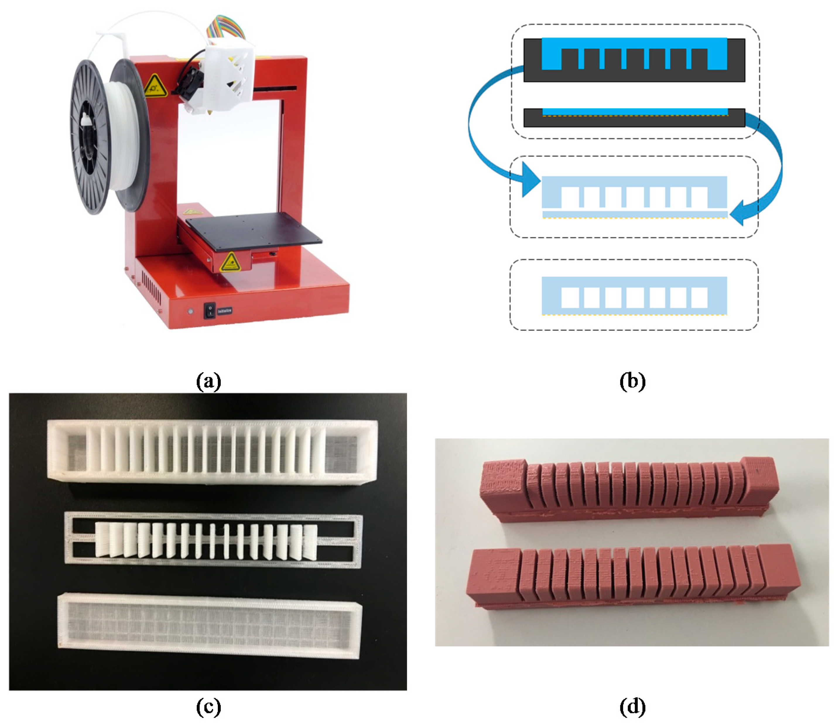
The fabrication process for the pneumatic actuator is shown in Figure 12, and the fabricated actuator is shown in Figure 12d. The pneumatic actuator consists of two layers that are moulded separately and then combined after curing. The upper layer is the active layer, composed of several channels; the lower layer is the passive layer. The liquid silicone rubber was poured separately into moulds that were prepared using a low-cost 3D printer. These two parts were cured at a certain temperature, and a thin layer of the uncured silicone rubber was used as the glue to bond these two pieces together. The fabrication steps are as follows:
- Prepare the 3D-printed mould: 3D printing, which is a rapid manufacturing method, can print almost any 3D object with a reasonable size and provides convenience for fabricating actuators with various structures. A low-cost 3D printer was used to fabricate the mould, as shown in Figure 12a. The mould consists of three parts.
- Prepare two silicone rubbers: the silicone and curing agent were mixed, with a 9:1 volume-to-weight ratio. The mixed liquid was then poured into the 3D-printed moulds for moulding and curing. The stirring and pouring processes generate a lot of air bubbles, which lead to leaking problems for the structure. Therefore, after the two parts were well mixed and the mixed liquid was placed into the mould, a vacuum pump was used to remove the air bubbles.
- Curing: the mould and liquid were put into the oven until these two parts of the main body were cured at a particular temperature (the M4601 was cured at 70 degrees centigrade for 20 min; curing time depends on the temperature).
- Remove the two parts of the actuator from the mould. Combine the two parts using uncured silicone rubber as the glue.
4. Comparison of Simulation and Experimental Results
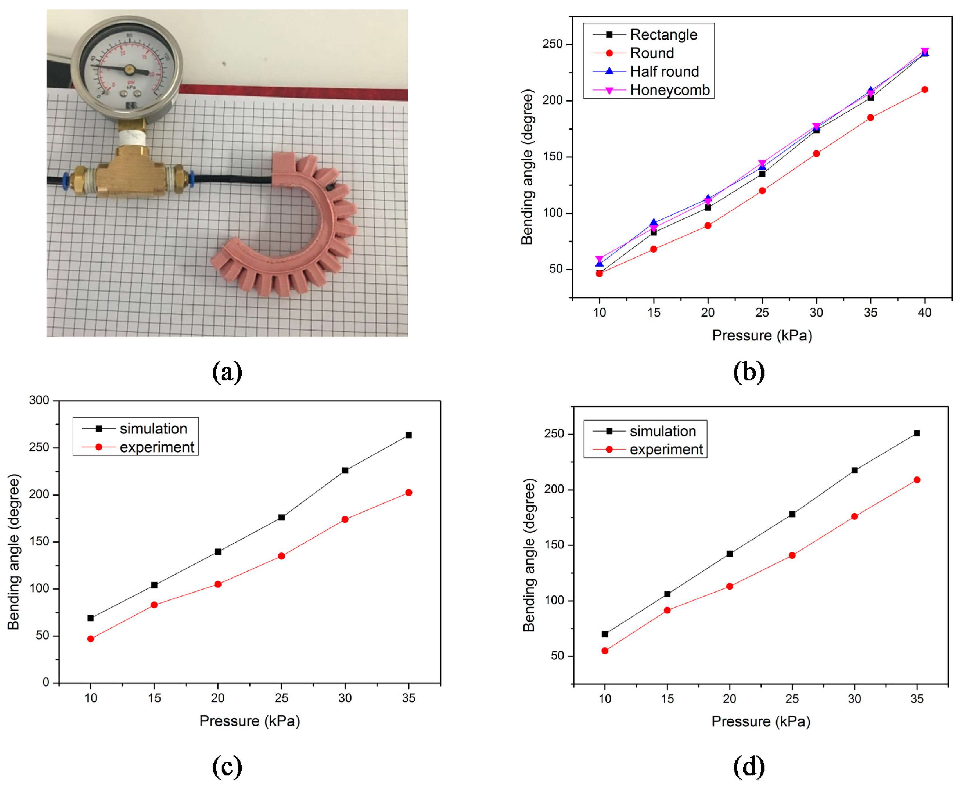
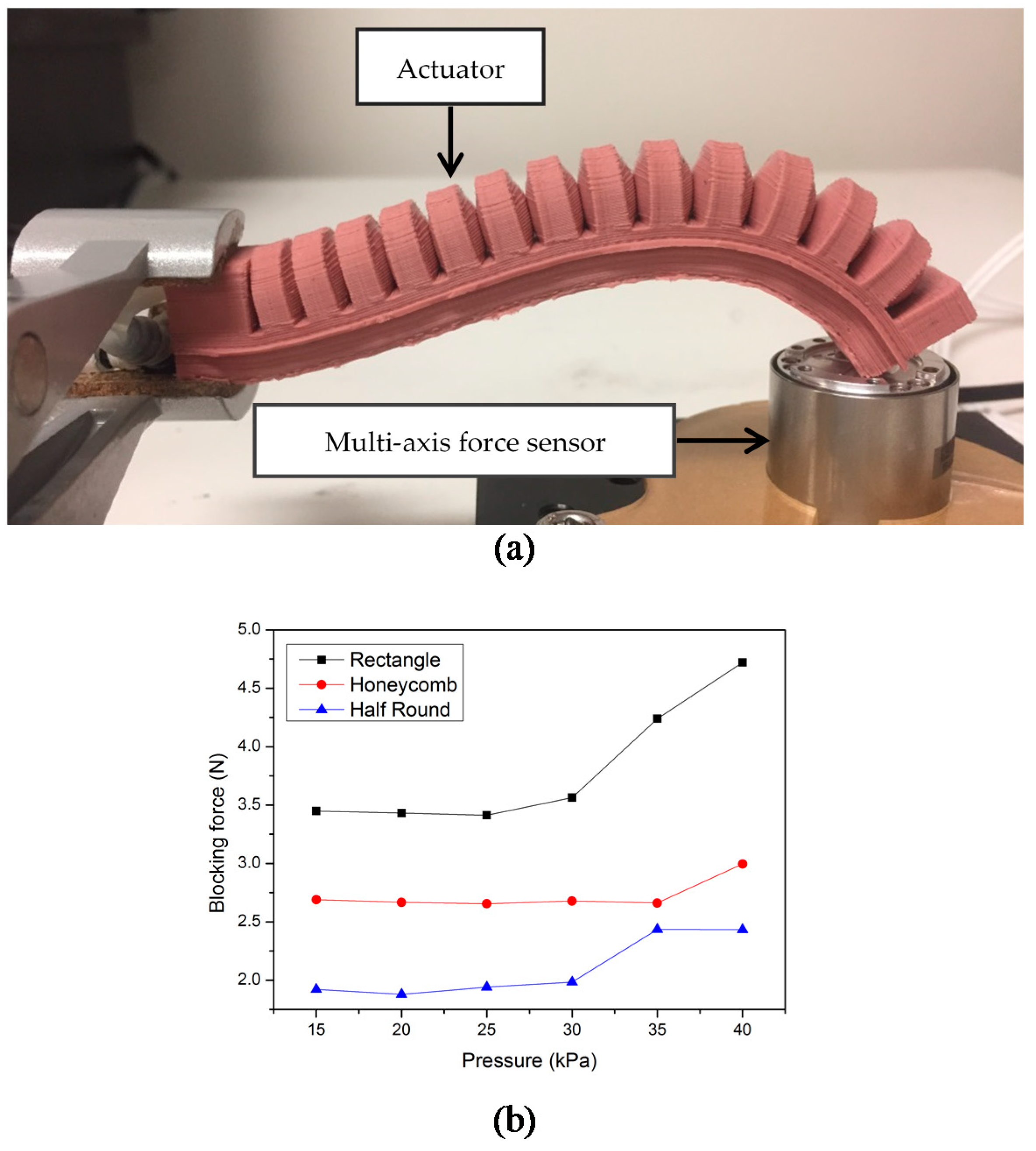
Experiments were conducted to verify the simulation results. The optimised parameters selected in Section 2 were used in the experiment samples. The pneumatic actuator was actuated by a miniature pump. The actuators with rectangular, honeycomb, half-round, and round cross sections were fabricated using the process outlined in Figure 12, and then the bending angles under the same pressure were compared. For each cross section, three measurements were performed, and the average value was selected as the final result. The simulation and experimental results agree well, as shown in Figure 13. The actuator with the round cross section can provide the smallest bending angle. It appears that there is a deviation of 19–30 degrees between the simulation and experimental results, as shown in Figure 13c,d. That means that the predicted bending angle is larger than the experimental result. Since the simulation is conducted under a relatively ideal environment, some pressure losses, for example, in the pneumatic network and associated pipes, are not considered in the simulation conditions and results. This issue and some other experimental errors cannot be avoided and may result in the offset between the experimental results and simulation results. The blocking force was tested and the results are shown in Figure 14. A 6-axis multi-axis force sensor (K6D Multicomponent Sensor, ME-Meßsysteme GmbH, Neuendorfstr, Germany) was used to measure the force generated by the tip of the finger, which is the blocking force. One end of the actuator was fixed to act as a cantilever beam. As the input pressure increases, there will be an increase in the output force. Before 30 kPa, the gradient increases slightly. When a relatively small pressure is applied to the actuator, the bending angle is small, and the blocking force is mainly caused by the weight of the actuator. The gradient increases significantly after 30 kPa. The sensor generates a resistance to the bending movements of the actuator when the input pressure is large enough. The actuator will make contact with the sensor base and bend in an arch, as shown in Figure 14. When inflated, the upper layer of the actuator extends and moves forward. The bending movements and contact with the sensor can be attributed to the increase in the blocking force.
5. Conclusions
This paper has presented a design optimisation method utilising finite element modelling to optimise a soft pneumatic actuator structure. The effects of various actuator parameters were studied to obtain a better understanding of the actuation performance for the slender pneumatic actuator to be used for soft robotic applications. By using the developed static structural model for the pneumatic network actuator, the critical design parameters were numerically evaluated, including the effects of input pressure, wall thickness, bottom layer thickness, distance between sequential chambers, and cross-sectional shape of the channels on the actuator deformation. ANOVA analysis was performed to systematically identify the significance of variables affecting deformation and, thus, the bending angle of the pneumatic actuator. After the FE simulations, the soft actuator with optimised parameters was fabricated. Experiments were conducted to quantify the performance of the optimised soft actuator. Simulation results correlate with experimental tests. The optimisation method followed in this study can easily be prolonged to develop various soft robotic structures to improve design performance prior to fabrication. The overarching objective of this study was to develop flexible fluidic actuators. This optimisation method will be extended to the design of the pneumatic actuators to be strategically placed on a hand and finger rehabilitation glove. We will report on this study in the near future.
Author Contributions
W.H. and G.A. conceived of the presented idea. G.A. supervised the project. W.H. contributed to the analysis, experiments and wrote the draft of the manuscript with support from R.M., W.L. and G.A. All authors discussed the results and contributed to the final manuscript.
Funding
This study is supported by ARC Centre of Excellence for Electromaterials Science (ACES) (Grant No. CE140100012), and the Intelligent Nano-Tera Research Systems Laboratory at University of Wollongong. The first author’s PhD study is sponsored by the Chinese Scholarship Council, which is greatly appreciated.
Conflicts of Interest
The authors declare no conflict of interest.
References
- Trivedi, D.; Rahn, C.D.; Kier, W.M.; Walker, I.D. Soft robotics: Biological inspiration, state of the art, and future research. Appl. Bionics Biomech. 2008, 5, 99–117. [Google Scholar] [CrossRef]
- Bauer, S.; Bauer-Gogonea, S.; Graz, I.; Kaltenbrunner, M.; Keplinger, C.; Schwödiauer, R. 25th anniversary article: A soft future: From robots and sensor skin to energy harvesters. Adv. Mater. 2014, 26, 149–162. [Google Scholar] [CrossRef] [PubMed] [Green Version]
- Rus, D.; Tolley, M.T. Design, fabrication and control of soft robots. Nature 2015, 521, 467–475. [Google Scholar] [CrossRef] [PubMed] [Green Version]
- Alici, G. Softer is Harder: What Differentiates Soft Robotics from Hard Robotics? MRS Adv. 2018, 3, 1557–1568. [Google Scholar] [CrossRef]
- Mosadegh, B.; Polygerinos, P.; Keplinger, C.; Wennstedt, S.; Shepherd, R.F.; Gupta, U.; Shim, J.; Bertoldi, K.; Walsh, C.J.; Whitesides, G.M. Pneumatic Networks for Soft Robotics that Actuate Rapidly. Adv. Funct. Mater. 2014, 24, 2163–2170. [Google Scholar] [CrossRef] [Green Version]
- Ilievski, F.; Mazzeo, A.D.; Shepherd, R.F.; Chen, X.; Whitesides, G.M. Soft robotics for chemists. Angew. Chem. 2011, 123, 1930–1935. [Google Scholar] [CrossRef] [Green Version]
- Onal, C.D.; Rus, D. A modular approach to soft robots. In Proceedings of the 2012 4th IEEE RAS & EMBS International Conference in Biomedical Robotics and Biomechatronics (BioRob), Roma, Italy, 24–27 June 2012; pp. 1038–1045. [Google Scholar]
- Polygerinos, P.; Lyne, S.; Wang, Z.; Nicolini, L.F.; Mosadegh, B.; Whitesides, G.M.; Walsh, C.J. Towards a soft pneumatic glove for hand rehabilitation. In Proceedings of the 2013 IEEE/RSJ International Conference on Intelligent Robots and Systems (IROS), Tokyo, Japan, 3–7 November 2013; pp. 1512–1517. [Google Scholar]
- Hwang, Y.; Paydar, O.H.; Candler, R.N. Pneumatic microfinger with balloon fins for linear motion using 3D printed molds. Sens. Actuators A Phys. 2015, 234, 65–71. [Google Scholar] [CrossRef]
- Wakimoto, S.; Suzumori, K.; Ogura, K. Miniature pneumatic curling rubber actuator generating bidirectional motion with one air-supply tube. Adv. Robot. 2011, 25, 1311–1330. [Google Scholar] [CrossRef]
- Paoletti, P.; Jones, G.W.; Mahadevan, L. Grasping with a soft glove: Intrinsic impedance control in pneumatic actuators. J. R. Soc. Interface 2017, 14, 20160867. [Google Scholar] [CrossRef] [PubMed]
- Shepherd, R.F.; Ilievski, F.; Choi, W.; Morin, S.A.; Stokes, A.A.; Mazzeo, A.D.; Chen, X.; Wang, M.; Whitesides, G.M. Multigait soft robot. Proc. Natl. Acad. Sci. USA 2011, 108, 20400–20403. [Google Scholar] [CrossRef] [PubMed] [Green Version]
- Morin, S.A.; Shepherd, R.F.; Kwok, S.W.; Stokes, A.A.; Nemiroski, A.; Whitesides, G.M. Camouflage and display for soft machines. Science 2012, 337, 828–832. [Google Scholar] [CrossRef] [PubMed] [Green Version]
- Onal, C.D.; Chen, X.; Whitesides, G.M.; Rus, D. Soft mobile robots with on-board chemical pressure generation. In Proceedings of the International Symposium on Robotics Research, Flagstaff, AZ, USA, 9–12 December 2011; pp. 1–16. [Google Scholar] [CrossRef]
- Correll, N.; Önal, Ç.D.; Liang, H.; Schoenfeld, E.; Rus, D. Soft autonomous materials—Using active elasticity and embedded distributed computation. Exp. Robot. 2014, 227–240. [Google Scholar] [CrossRef]
- Tolley, M.T.; Shepherd, R.F.; Mosadegh, B.; Galloway, K.C.; Wehner, M.; Karpelson, M.; Wood, R.J.; Whitesides, G.M. A resilient, untethered soft robot. Soft Robot. 2014, 1, 213–223. [Google Scholar] [CrossRef]
- Homberg, B.S.; Katzschmann, R.K.; Dogar, M.R.; Rus, D. Haptic identification of objects using a modular soft robotic gripper. In Proceedings of the 2015 IEEE/RSJ International Conference on Intelligent Robots and Systems (IROS), Hamburg, Germany, 28 September–2 October 2015; pp. 1698–1705. [Google Scholar]
- Yap, H.K.; Lim, J.H.; Nasrallah, F.; Goh, J.C.; Yeow, R.C. A soft exoskeleton for hand assistive and rehabilitation application using pneumatic actuators with variable stiffness. In Proceedings of the 2015 IEEE International Conference on Robotics and Automation (ICRA), Seattle, WA, USA, 26–30 May 2015; pp. 4967–4972. [Google Scholar]
- Suzumori, K.; Iikura, S.; Tanaka, H. Flexible microactuator for miniature robots. In Proceedings of the 1991 Micro Electro Mechanical Systems (MEMS’91), An Investigation of Micro Structures, Sensors, Actuators, Machines and Robots, Nara, Japan, 30 January–2 February 1991; pp. 204–209. [Google Scholar]
- Marchese, A.D.; Katzschmann, R.K.; Rus, D. Whole arm planning for a soft and highly compliant 2d robotic manipulator. In Proceedings of the 2014 IEEE/RSJ International Conference on Intelligent Robots and Systems (IROS 2014), Chicago, IL, USA, 14–18 September 2014; pp. 554–560. [Google Scholar]
- Galloway, K.C.; Becker, K.P.; Phillips, B.; Kirby, J.; Licht, S.; Tchernov, D.; Wood, R.J.; Gruber, D.F. Soft robotic grippers for biological sampling on deep reefs. Soft Robot. 2016, 3, 23–33. [Google Scholar] [CrossRef] [PubMed]
- Giffney, T.; Xie, M.; Yong, A.; Wong, A.; Mousset, P.; McDaid, A.; Aw, K. Soft pneumatic bending actuator with integrated carbon nanotube displacement sensor. Robotics 2016, 5, 7. [Google Scholar] [CrossRef]
- Case, J.C.; White, E.L.; Kramer, R.K. Soft material characterization for robotic applications. Soft Robot. 2015, 2, 80–87. [Google Scholar] [CrossRef]
- Alici, G.; Canty, T.; Mutlu, R.; Hu, W.; Sencadas, V. Modelling and Experimental Evaluation of Bending Behaviour of Soft Pneumatic Actuators Made of Discrete Actuation Chambers. Soft Robot. 2018, 5, 24–35. [Google Scholar] [CrossRef] [PubMed]
Figure 1.
(a) Longitudinal cross section of the actuator; (b) The effect of the input pressure on bending angle; (c) The bending angle under different input pressures.
Figure 1.
(a) Longitudinal cross section of the actuator; (b) The effect of the input pressure on bending angle; (c) The bending angle under different input pressures.

Figure 2.
The bending angle change with Young’s modulus of the actuator material.

Figure 3.
The effect of material stiffness on bending angles under the same test pressure (20 kPa).

Figure 4.
(a) Residual histogram for bending angle (degree); (b) Residuals versus fits for bending angle (degree).
Figure 4.
(a) Residual histogram for bending angle (degree); (b) Residuals versus fits for bending angle (degree).
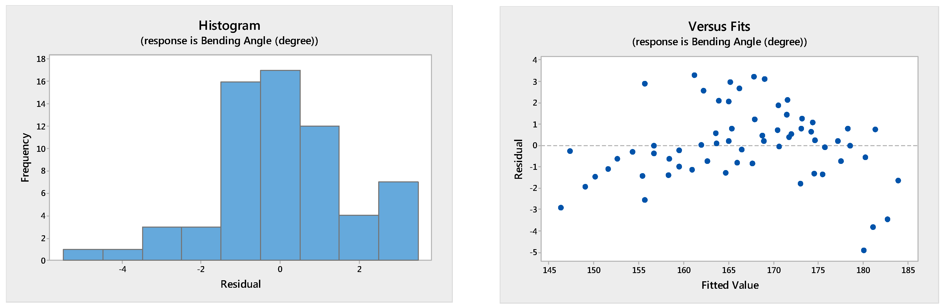
Figure 5.
Bending angle versus bottom layer thickness.

Figure 6.
(a) The effect of the gap between adjacent channels; (b) Variation of the bending angle with the gap size between the adjacent channels.
Figure 6.
(a) The effect of the gap between adjacent channels; (b) Variation of the bending angle with the gap size between the adjacent channels.

Figure 7.
Variation of the bending angle with the wall thickness.

Figure 8.
Cross section of the chamber (a, b represent the inside dimensions, a0, b0 represent the outside dimensions, t is bottom layer thickness, and w is wall thickness).
Figure 8.
Cross section of the chamber (a, b represent the inside dimensions, a0, b0 represent the outside dimensions, t is bottom layer thickness, and w is wall thickness).

Figure 9.
The variation of the ratio with the wall thickness.

Figure 10.
The effect of wall thickness and bottom layer thickness.

Figure 11.
Variation of the bending angle with different cross sections. (a) Simulation results. (b) Cross sections considered in this study: (1) rectangular cross section; (2) honeycomb cross section; (3) half-round cross section and (4) round cross section. (c) Bending shape with different cross sections under 35 kPa pressure.

Figure 12.
Fabrication procedure and the moulded actuators: (a) 3D printer (3D Printing. Systems, UP Plus 2); (b) fabrication procedure; (c) 3D-printed mould; (d) the moulded actuator.
Figure 12.
Fabrication procedure and the moulded actuators: (a) 3D printer (3D Printing. Systems, UP Plus 2); (b) fabrication procedure; (c) 3D-printed mould; (d) the moulded actuator.

Figure 13.
The comparison of the experimental and simulation results for the bending angle: (a) bending shape of a rectangular cross section actuator; (b) the experimental results with four different cross sections; (c) a comparison of the experimental and simulation results with a rectangular cross section; (d) a comparison of the experimental and simulation results with a half-round cross section.

Figure 14.
Blocking force test: (a) the experimental setup to measure the blocking force and the bending shape during blocking force test process; (b) the blocking force results.
Figure 14.
Blocking force test: (a) the experimental setup to measure the blocking force and the bending shape during blocking force test process; (b) the blocking force results.


Table 1.
Typical general characteristics of M4601 (Barnes Products Pty Ltd, Sydney, Australia.).
| Property | Value |
|---|---|
| Elongation at break | 700% |
| Mix ratio at | 9:1 |
| Hardness Shore A | 28 |
Table 2.
Variables employed in the simulation process.
| Parameters | Levels | |||
|---|---|---|---|---|
| Wall thickness (mm) | 1 | 1.25 | 1.5 | 1.75 |
| Bottom layer thickness (mm) | 4.5 | 5 | 5.5 | 6 |
| Gap between the adjacent channels (mm) | 1 | 1.25 | 1.5 | 1.75 |
Table 3.
ANOVA results for the bending angle versus wall thickness, gap size, and bottom thickness.
| Source | Degree of Freedom | F-Value | p-Value |
|---|---|---|---|
| Bottom layer thickness | 3 | 332.91 | ˂5% |
| Gap size | 3 | 13.36 | ˂5% |
| Wall thickness | 3 | 185.55 | ˂5% |
© 2018 by the authors. Licensee MDPI, Basel, Switzerland. This article is an open access article distributed under the terms and conditions of the Creative Commons Attribution (CC BY) license (http://creativecommons.org/licenses/by/4.0/).
Share and Cite
MDPI and ACS Style
Hu, W.; Mutlu, R.; Li, W.; Alici, G. A Structural Optimisation Method for a Soft Pneumatic Actuator. Robotics 2018, 7, 24. https://doi.org/10.3390/robotics7020024
AMA Style
Hu W, Mutlu R, Li W, Alici G. A Structural Optimisation Method for a Soft Pneumatic Actuator. Robotics. 2018; 7(2):24. https://doi.org/10.3390/robotics7020024
Chicago/Turabian StyleHu, Weiping, Rahim Mutlu, Weihua Li, and Gursel Alici. 2018. "A Structural Optimisation Method for a Soft Pneumatic Actuator" Robotics 7, no. 2: 24. https://doi.org/10.3390/robotics7020024
Note that from the first issue of 2016, this journal uses article numbers instead of page numbers. See further details here.