Propulsion-Based Soft Robotic Actuation


1
Institute of Systems Science, National University of Singapore, Singapore 119615, Singapore
2
Department of Biomedical Engineering, National University of Singapore, Singapore 117575, Singapore
*
Author to whom correspondence should be addressed.
Robotics 2017, 6(4), 34; https://doi.org/10.3390/robotics6040034
Submission received: 28 September 2017
/
Revised: 18 November 2017
/
Accepted: 23 November 2017
/
Published: 24 November 2017
(This article belongs to the Special Issue Mechanics, Control, Design, Conceptualization and Fabrication of Soft Robotic Systems)
Abstract
:The use of air propulsion to drive limb motion in soft robotics has been a largely untapped field even though the technology has been around since the 1700s. Air propulsion can generate greater degrees of motion in limb actuators compared to widely-experimented pneumatic actuators operating on expandable air channels, which are limited by air pressure input, minimum size and cyclic fatigue. To demonstrate the application of air propulsion in soft robotics motion, we developed a 3D-printed, tri-pedal, soft, air-driven robot that can perform biomimetic motions such as flexion and extension of limbs, crawling, rotation, grasping, kicking and picking of objects. To accomplish air-propelled actuation, milli-scale channels are incorporated throughout each limb that guides the pressurized air inflow to outlets of different directions. A Finite Element Model (FEM) approach to simulate the bending response of the limb due to varying pressure is proposed and evaluated. This study introduces the potential of using air propulsion as an alternate form of soft body actuation for longer cyclic lifespan and increased maximum air pressure input.
1. Introduction
Air propulsion has been around for centuries since John Wilkinson introduced the first air compressor prototype in 1762 [1]. To date, this technology has matured and is ubiquitous in our daily lives, and can be found in jet planes, factory air compressors, gas powered pistons and so on. The working mechanism behind air propulsion lies in the creation of kinetic motion through directional exertion of pressurized air either through combustion or an air reservoir [2]. Although air propulsion generates bending in soft flexible bodies during motion as an inevitable effect [3,4,5], there has been minimal investigation done into the use of air propulsion to create soft body locomotion to perform tasks. In this paper, we study and present air-propelled actuation methods in soft robotics, which is the use of pressurized air through mini-channels and out of an outlet, to generate bending and flexing motions in robotic limbs.
Pneumatic-actuated soft robotics have been a widely studied field recently, and their applications range from medical devices [6,7,8,9], to biomimetic robots [10,11] and artificial muscles [12,13]. These pneumatic-actuated soft robots generally have customized and expandable internal air channels that results in overall locomotion when air is pumped in [7,14]. However, there are several limitations with these pneumatic actuators. Firstly, the amount of input air pressure is highly limited by the strength of the polymeric material used [15]. This factor restricts the speed and force of the actuation as air pressure has to be controlled. Secondly, due to the walls of the pneumatic actuators experiencing tensile stress and elastic deformation, there needs to be a minimum wall thickness to ensure durability. Additionally, the channel dimensions and geometry are determined by the resultant stiffness of the materials used in these actuators [7], therefore resulting in bulky sizes that they presently have [16]. Thirdly, most of these soft actuators are made of hyper-elastic materials that are prone to hysteresis after multiple cycles of tension and relaxation, giving rise to compliance issues [7,17,18,19]. Thus, an alternate mean of utilizing pneumatic energy to drive such robots is required if size, speed, actuation and durability are to be addressed.
In this paper, we demonstrate the use of air propulsion as a mean to create locomotion in soft robotic limbs. The main aims of this study were to show that air propulsion technology can: (i) produce biomimetic motion; (ii) shrink down the size of actuators; (iii) circumvent durability issues in traditional pneumatic actuators; and (iv) generate enough actuating force to perform simple tasks. We also propose a finite element approach to model the bending of the robotic limb due to air propulsion. Section 2 presents the design of the air-driven robot, a finite element modeling approach and the experimental setup. Section 3 presents the results of the experiments and simulation while Section 4 and Section 5 present some applications and discussion, respectively. The paper finally concludes in Section 6.
2. Methods and Materials
2.1. Design of Air-Driven Robot
The soft robot consists of 3 flexible limbs and 3 lateral thrusters printed using NinjaFlex® [20], consisting of thermoplastic polyurethane, with a commercial 3D printer (Figure 1). The material properties of NinjaFlex® can be found in Table 1. The total rapid prototyping time took around 4 h and each limb module was printed separately and later joined together.
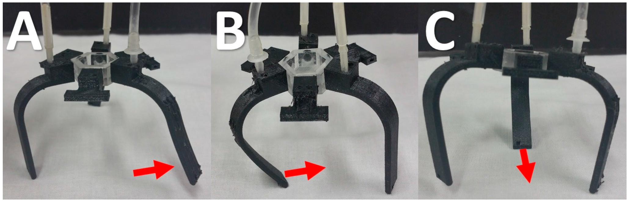
The limbs were designed to mimic simple flexion and extension motions. This requires two separate air channels to be incorporated side by side within each limb (Figure 2A). A CAD model of a limb and its cross sections are shown in Figure 2. Each channel started from the top of the limb where the air source was connected to, and runs continued to the bottom of the limb, ending in opposite directions (Figure 2B,C). The dimensions of the channel cross section were 2 mm × 1 mm throughout the limb and the wall thickness was around 1 mm. We observed that, below this wall thickness, the actuators walls became porous, resulting in ineffective air propulsion due to leakage. The limb actuators were also kept as thin as possible to maximize flexibility in the actuating plane. Additionally, to ensure optimal flexibility, the limbs had to be printed in the orientation where the cross section was parallel to the tabletop surface. Besides the air propelled limbs, the air-driven robot also consisted of three lateral thrusters (Figure 2D), which enabled the robot to perform quick rotation and to change its direction of travel. Similar to the actuating limb, the thrusters had two air channels that pointed to opposite directions (Figure 2E). For input pressure large enough to overcome static friction, one lateral thruster was sufficient to achieve rotation, which reduced the number of pneumatic connection to 8 for 2 degrees of freedom (DOF) movement.
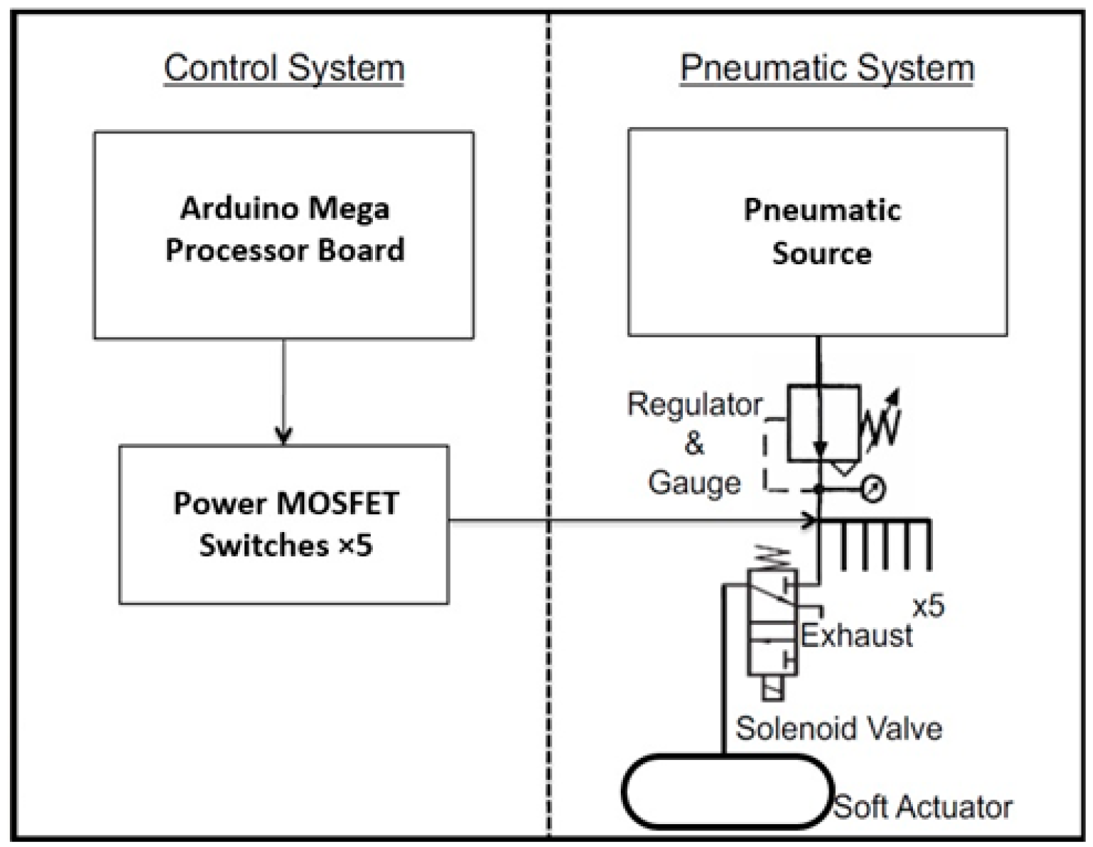
The flexion and extension of the limbs were attained through channeling the pressurized airflow into either of the two top inlets (Video S1). The greater the air pressure input, the larger the bending displacement of the limb was. Using all three air propelled limbs resulted in the crawling locomotion of the air-driven robot (Video S2). The input pressure needed to be controlled at around 3 bars to perform this crawling motion, where each gait cycle sequence started off with the extension of its frontal limb (Figure 3A), followed by the flexion of its right rear limb (Figure 3B) and lastly the flexion of the left rear limb (Figure 3C). The second movement locomotion demonstrated was the hopping of the air-driven robot (Video S3), which had greater velocity compared to crawling. To achieve this, the air pressure of 4 bars and above was used to generate more acceleration through the back-facing outlet of the frontal limb. These air-propelled actuation modes demonstrate the possibility of achieving biomimetic motions, similar to that of animals and insects. Figure 4 shows the complete system setup of the prototype whereby the air compressor was connected to an Arduino Mega processor board and subsequently to the actuators. Different square wave cyclic signals can be programmed into the system to control the input pressure for customized control of motion.
2.2. Finite Element Modeling of Limb Bending
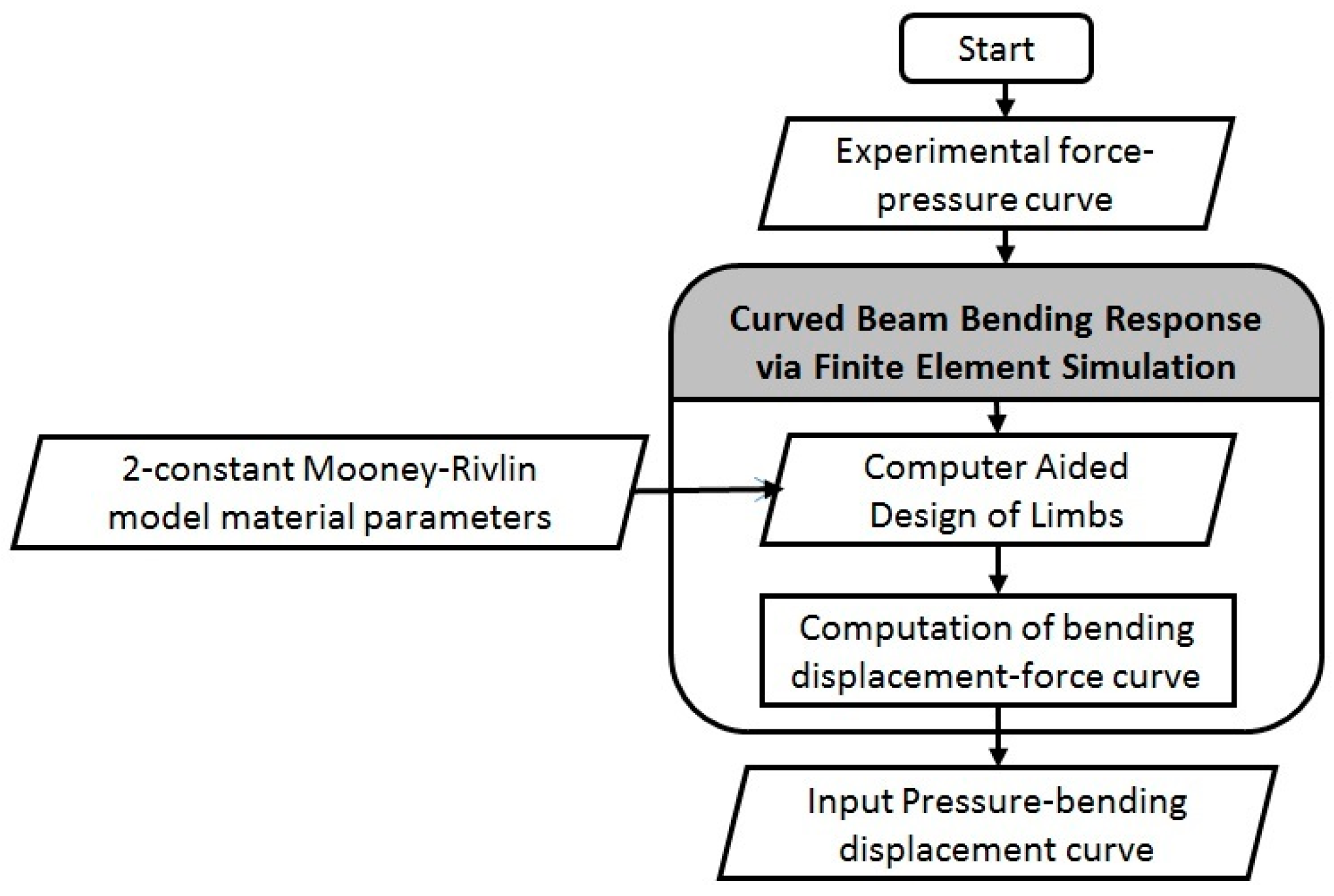
To model the bending of a curved flexible beam due to varying air pressure input, a Finite Element Modeling (FEM) approach is proposed in this paper (Figure 5). To the authors’ best knowledge, little or no prior modeling work has been performed on the bending of curved actuator beams created by air propulsion.
The experimental actuating force to input pressure was first obtained from the robotic limb under various pressures. A model of the robotic limb was then import into COMSOL Multiphysics® software for finite element simulation. The mechanical behavior of the NinjaFlex® material was represented by the 2-constant Mooney–Rivlin model [22,23]:
where W is the strain energy function, C10 and C01 are the material parameters, and I1 and I2 are the strain invariants. The values of the parameters were C10 = 1.653 MPa and C01 = 1.621 MPa, as obtained from our previous work [24]. Computation simulation was then performed with various experimental forces to obtain the bending displacement of the curved beam. Finally, the relationship between the bending displacement and the respective input pressure was established, allowing for better understanding and control of the robotic limb.
2.3. Mechanical Experimental Setup and Evaluation
Initial measurements of actuating force to various input pressures were carried out (Figure 6A) using a load sensor. Pneumatic limbs with square outlets of length 2 mm and 3 mm were fabricated. The tip of a Digital Force Gauge DS2-50N (Imada, Northbrook, IL, USA) was placed perpendicular to the surface of a pneumatic limb at 2 mm from the distal end, and pressurized air ranging from 0 to 5 bars was used. For the experimental evaluation of the proposed FEM approach, the horizontal displacement of the actuator limb was measured at various input pressures (Figure 6B). Care was taken to ensure that the displacement of the limb has reached equilibrium with constant airflow, before measurements were recorded. Ten readings of each data point were taken.
3. Results
3.1. Experimental
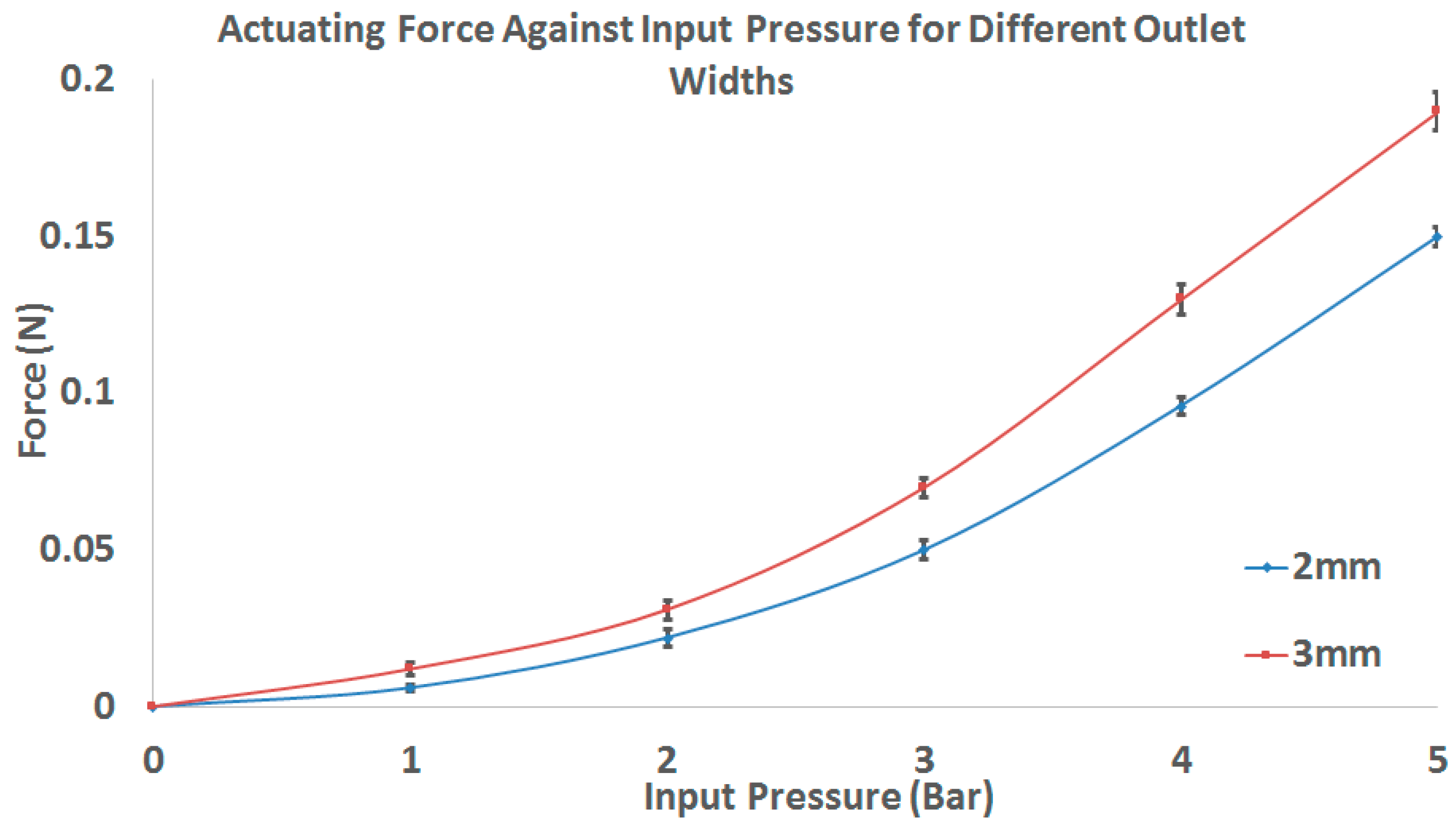
The results for the experimental force-pressure curve are presented in Figure 7. The outlet width of 3 mm could achieve greater actuating force than that of 2 mm. However, further increase in width above 3 mm were not tested due to the geometric constraints of the actuator width. This was because to maintain the external width of the actuator as small as possible, any increment in the outlet width would result in the surrounding wall thickness dropping below 1 mm and becoming porous. A small actuator width allows the robot size to be kept small and reduce the amount of input air pressure needed to actuate it.
3.2. Simulation Results
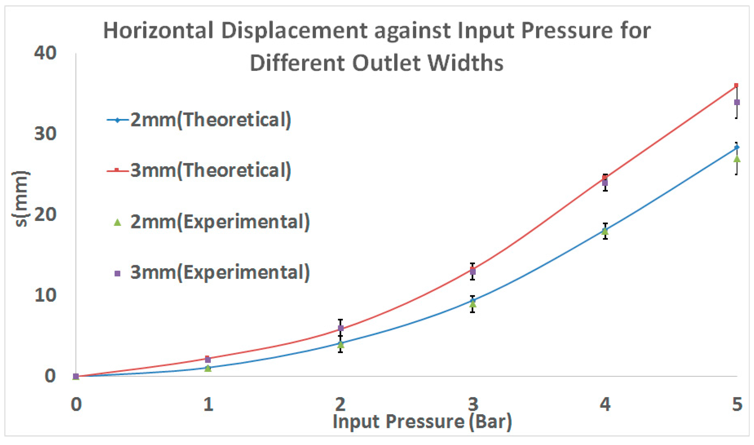
The finite element analysis simulation of the robotic limb model to obtain the theoretical displacement from the input force can be found in Figure 8. This approach allowed us to collate the predicted displacement results and compile them against their respective input pressures. The final predictive quadratic polynomials for 2 mm and 3 mm outlet widths are presented as:
respectively, where s is the displacement (mm) and p is the input pressure (bars). The predictive equations were plotted out and compared against experimental readings (Figure 9). The simulation results can be observed to be within one standard deviation of the experimental data. An increasing discrepancy between theoretical and experimental results can be observed as pressure increases due to increasing head loss of airflow through the channel.
4. Application of Air-Driven Robot
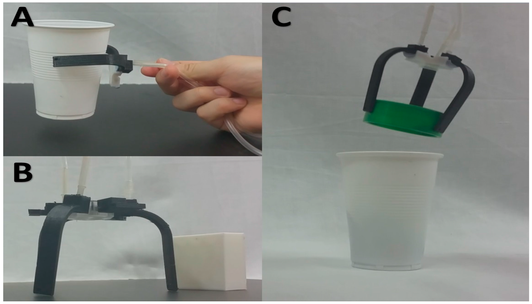
In a more application-based approach, we used the air-driven robot to perform simple manipulation tasks. The first task was to grip a 15-g plastic cup and lift it off the ground and then lower it back down (Figure 10A, Video S4). For this purpose, only two limbs angled at 120° were used with an input pressure of 3 bars. It was observed that the highly compliant actuators could conform to the surface curvature of the cup and maintain enough friction to lift the latter off the table. The second task involved picking up a roll of tape and depositing it into a plastic cup (Figure 10C, Video S5). Because the diameter of the roll of tape is less than that of the previous cup, the input pressure had to be increased to 4 bars to achieve greater bending curvature and also to compensate for the head loss due to an additional actuator. Lastly, the robot was made to hop towards a plastic block and kick it with its front limb (Figure 10B, Video S6).
5. Discussion
There are several primary application areas for the air-driven robot. Due to its miniature size compared to other pneumatic-actuated robots, the former can be deployed in search and rescue missions, for example, in earthquake crisis where gaps between rubbles are small [25]. They can also be deployed for reconnaissance or surveillance [26,27] on uneven or compliant terrains since legged walking on such surfaces are more efficient than rolling wheels [28,29]. With sufficient air supply, hovering capabilities can be integrated into this air-propelled robot, creating a versatile drone that can transverse air, land and sea. Lastly, the use of air-propelled actuation can be utilized for medical devices like assistive exoskeletons [30,31] for rehabilitation. The potential of generating substantial amount of force through a small channel and aperture can streamline the size and weight of such exoskeleton designs. Lastly, the advantages of air-propelled soft limbs as compared to rigid limbs in tripedal robot [32,33] are that the former are more compliant to irregular surfaces, lighter and have more degrees of freedom.
The proposed finite element approach to predict the displacement response of the soft actuator limb to varying air pressures was validated. This approach allows for quick modification, evaluation and optimization of superficial limb design, provided the design of the air channel remains unchanged. The significance of such approach is for better control of the limb movements when designing control algorithms in future.
A limitation of this study is the small amount of output force. The force, although small, is sufficient to create biomimetic locomotion and perform simple tasks, which was the main aim of this paper. Future improvements to increase the output forces to perform more rigorous tasks can be achieved through greater input air pressure and improving the design of the channels and actuators to reduce air flow resistance and head loss. Future works can also include the dynamic behavior modeling of these actuators for better depth of understanding of their speed and performance.
The air-driven robot presents the potential application of air propulsion to achieve locomotion and elastic deformation of soft bodies. These soft air-propelled actuators can be scaled down to smaller sizes compared to conventional pneumatic air bladder actuators, without compromising on the durability and integrity. The robot presented in this paper is fabricated with a commercial 3D printer; it is inexpensive and can be easily modified to suit several applications. However, a major disadvantage of the proposed air propulsion actuation compared to conventional pneumatic approaches includes the requirement of a continuous air supply to maintain final shape. Another limitation would be the decreased actuating force compared to conventional pneumatic actuators. The air-propelled locomotion, which is demonstrated with the air-driven robot, opens up another untapped field of nature-inspired design that can be integrated into a myriad of drone and exoskeleton applications. The evaluation and comparison of the proposed air-propulsion actuator with our previous works in conventional pneumatic bladder actuators [6,36,37] is presented in Table 2.
6. Conclusions
In conclusion, we have demonstrated the feasibility of using air-propulsion to achieve biomimetic locomotion in soft 3-D printed robots. The tri-pedal robot can crawl, pinch, grasp and kick while powered from a pneumatic source. A finite element approach to model the displacement response of the curved actuator limb to varying input pressure was proposed and evaluated. This paper shows the potential of utilizing air-propulsion for bending and movement in soft robotics applications.
Supplementary Materials
The following are available online at www.mdpi.com/2218-6581/6/4/34/s1, Video S1: Flexion and extension of the soft robotic limb, Video S2: Crawling locomotion of the air-driven robot, Video S3: Hopping of the air-driven robot, Video S4: Gripping and lifting of a plastic cup with a pair of soft robotic limb, Video S5: Picking up of a roll of tape and depositing it into a plastic cup using the developed soft robotic limb, Video S6: Demonstration of the soft robot hopping towards a block and kicking it with its front limb.
Acknowledgments
This research work was funded by the Singapore Millennium Foundation Grant, grant number: R-397-000-258-592.
Author Contributions
Matthew Chin Heng Chua was involved in the development and experimentation of the soft robot. Raye Chen Hua Yeow was involved in the computational study and guidance of the project.
Conflicts of Interest
The authors declare no conflicts of interest.
References
- Jacobson, A. Air compressor lubricants: The next generation. Tribol. Lubr. Technol. 2004, 60, 30. [Google Scholar]
- Shepherd, R.F.; Stokes, A.A.; Freake, J.; Barber, J.; Snyder, P.W.; Mazzeo, A.D.; Cademartiri, L.; Morin, S.A.; Whitesides, G.M. Using explosions to power a soft robot. Angew. Chem. Int. Ed. 2013, 52, 2892–2896. [Google Scholar] [CrossRef] [PubMed]
- Lucas, K.N.; Johnson, N.; Beaulieu, W.T.; Cathcart, E.; Tirrell, G.; Colin, S.P.; Gemmell, B.J.; Dabiri, J.O.; Costello, J.H. Bending rules for animal propulsion. Nat. Commun. 2014, 5, 3293. [Google Scholar] [CrossRef] [PubMed]
- Albertani, R.; Stanford, B.; Hubner, J.; Ifju, P. Aerodynamic coefficients and deformation measurements on flexible micro air vehicle wings. Exp. Mech. 2007, 47, 625–635. [Google Scholar] [CrossRef]
- Combes, S.A.; Daniel, T.L. Into thin air: Contributions of aerodynamic and inertial-elastic forces to wing bending in the hawkmoth Manduca sexta. J. Exp. Biol. 2003, 206, 2999–3006. [Google Scholar] [CrossRef] [PubMed]
- Yap, H.K.; Goh, J.C.H.; Yeow, R.C.H. Design and Characterization of Soft Actuator for Hand Rehabilitation Application. In 6th European Conference of the International Federation for Medical and Biological Engineering: MBEC 2014, Dubrovnik, Croatia, 7–11 September 2014; Lacković, I., Vasic, D., Eds.; Springer International Publishing: Cham, Germany, 2015; pp. 367–370. [Google Scholar]
- Yap, H.K.; Lim, J.H.; Nasrallah, F.; Goh, J.C.; Yeow, R.C. A soft exoskeleton for hand assistive and rehabilitation application using pneumatic actuators with variable stiffness. In Proceedings of the 2015 IEEE International Conference on Robotics and Automation (ICRA), Seattle, WA, USA, 26–30 May 2015; pp. 4967–4972. [Google Scholar]
- Yap, H.K.; Lim, J.H.; Nasrallah, F.; Goh, J.C.H.; Yeow, C.-H. Characterisation and evaluation of soft elastomeric actuators for hand assistive and rehabilitation applications. J. Med. Eng. Technol. 2016, 40, 199–209. [Google Scholar] [CrossRef] [PubMed]
- Belforte, G.; Eula, G.; Ivanov, A.; Sirolli, S. Soft pneumatic actuators for rehabilitation. Actuators 2014, 3, 84–106. [Google Scholar] [CrossRef]
- Shepherd, R.F.; Ilievski, F.; Choi, W.; Morin, S.A.; Stokes, A.A.; Mazzeo, A.D.; Chen, X.; Wang, M.; Whitesides, G.M. Multigait soft robot. Proc. Natl. Acad. Sci. USA 2011, 108, 20400–20403. [Google Scholar] [CrossRef] [PubMed] [Green Version]
- Suzumori, K.; Endo, S.; Kanda, T.; Kato, N.; Suzuki, H. A bending pneumatic rubber actuator realizing soft-bodied manta swimming robot. In Proceedings of the 2007 IEEE International Conference on Robotics and Automation, Roma, Italy, 10–14 April 2007; pp. 4975–4980. [Google Scholar]
- Klute, G.K.; Czerniecki, J.M.; Hannaford, B. McKibben artificial muscles: Pneumatic actuators with biomechanical intelligence. In Proceedings of the 1999 IEEE/ASME International Conference on Advanced Intelligent Mechatronics, Atlanta, Georgia, 19–23 September 1999; pp. 221–226. [Google Scholar]
- Tondu, B.; Ippolito, S.; Guiochet, J.; Daidie, A. A seven-degrees-of-freedom robot-arm driven by pneumatic artificial muscles for humanoid robots. Int. J. Robot. Res. 2005, 24, 257–274. [Google Scholar] [CrossRef]
- Polygerinos, P.; Lyne, S.; Wang, Z.; Nicolini, L.F.; Mosadegh, B.; Whitesides, G.M.; Walsh, C.J. Towards a soft pneumatic glove for hand rehabilitation. In Proceedings of the 2013 IEEE/RSJ International Conference on Intelligent Robots and Systems (IROS), Tokyo, Japan, 3–7 November 2013; pp. 1512–1517. [Google Scholar]
- Martinez, R.V.; Fish, C.R.; Chen, X.; Whitesides, G.M. Elastomeric Origami: Programmable Paper-Elastomer Composites as Pneumatic Actuators. Adv. Funct. Mater. 2012, 22, 1376–1384. [Google Scholar] [CrossRef] [Green Version]
- Laschi, C.; Mazzolai, B.; Mattoli, V.; Cianchetti, M.; Dario, P. Design of a biomimetic robotic octopus arm. Bioinspir. Biomim. 2009, 4, 015006. [Google Scholar] [CrossRef] [PubMed]
- Mosadegh, B.; Polygerinos, P.; Keplinger, C.; Wennstedt, S.; Shepherd, R.F.; Gupta, U.; Shim, J.; Bertoldi, K.; Walsh, C.J.; Whitesides, G.M. Pneumatic networks for soft robotics that actuate rapidly. Adv. Funct. Mater. 2014, 24, 2163–2170. [Google Scholar] [CrossRef]
- Chou, C.-P.; Hannaford, B. Static and dynamic characteristics of McKibben pneumatic artificial muscles. In Proceedings of the 1994 IEEE International Conference on Robotics and Automation, San Diego, CA, USA, 8–13 May 1994; pp. 281–286. [Google Scholar]
- Kingsley, D.A.; Quinn, R.D. Fatigue life and frequency response of braided pneumatic actuators. In Proceedings of the ICRA’02. IEEE International Conference on Robotics and Automation, Washington, DC, USA, 11–15 May 2002; pp. 2830–2835. [Google Scholar]
- Bahr, R.; Le, T.; Tentzeris, M.M.; Moscato, S.; Pasian, M.; Bozzi, M.; Perregrini, L. RF characterization of 3D printed flexible materials-NinjaFlex Filaments. In Proceedings of the 2015 European Microwave Conference (EuMC), Paris, France, 7–10 September 2015; pp. 742–745. [Google Scholar]
- Soe, S.; Theobald, P. Energy Absorbing Characteristics of Additively Manufactured TPE Cellular Structures. In Proceedings of the 2nd International Conference on Sustainable Design and Manufacturing, Seville, Spain, 12–14 April 2015. [Google Scholar]
- Boyce, M.C.; Arruda, E.M. Constitutive models of rubber elasticity: A review. Rubber Chem. Technol. 2000, 73, 504–523. [Google Scholar] [CrossRef]
- Wang, W.; Deng, T.; Zhao, S.-G. Determination for Material Constants of Rubber Mooney-Rivlin Model. Spec. Purp. Rubber Prod. 2004, 4. [Google Scholar]
- Yap, H.K.; Ng, H.Y.; Yeow, C.-H. High-Force Soft Printable Pneumatics for Soft Robotic Applications. Soft Robot. 2016, 3, 144–158. [Google Scholar] [CrossRef]
- Murphy, R.R.; Tadokoro, S.; Nardi, D.; Jacoff, A.; Fiorini, P.; Choset, H.; Erkmen, A.M. Search and rescue robotics. In Springer Handbook of Robotics; Springer: Berlin, Germany, 2008; pp. 1151–1173. [Google Scholar]
- Hougen, D.F.; Benjaafar, S.; Bonney, J.C.; Budenske, J.R.; Dvorak, M.; Gini, M.; French, H.; Krantz, D.G.; Li, P.Y.; Malver, F. A miniature robotic system for reconnaissance and surveillance. In Proceedings of the IEEE International Conference on Robotics and Automation, San Francisco, CA, USA, 24–28 April 2000; pp. 501–507. [Google Scholar]
- Matthies, L.; Xiong, Y.; Hogg, R.; Zhu, D.; Rankin, A.; Kennedy, B.; Hebert, M.; Maclachlan, R.; Won, C.; Frost, T. A portable, autonomous, urban reconnaissance robot. Robot. Auton. Syst. 2002, 40, 163–172. [Google Scholar] [CrossRef]
- Scarfogliero, U.; Stefanini, C.; Dario, P. A bioinspired concept for high efficiency locomotion in micro robots: The jumping Robot Grillo. In Proceedings of the ICRA 2006 IEEE International Conference on Robotics and Automation, Orlando, FL, USA, 15–19 May 2006; pp. 4037–4042. [Google Scholar]
- Buksh, S.R.; Chen, X.; Wang, W. Study of flea jumping mechanism for biomimetic robot design. J. Biomech. Sci. Eng. 2010, 5, 41–52. [Google Scholar] [CrossRef]
- Tsagarakis, N.; Caldwell, D.; Medrano-Cerda, G. A 7 DOF pneumatic muscle actuator (pMA) powered exoskeleton. In Proceedings of the 8th IEEE International Workshop on Robot and Human Interaction, Pisa, Italy, 27–29 September 1999; pp. 327–333. [Google Scholar]
- Malcolm, P.; Derave, W.; Galle, S.; de Clercq, D. A simple exoskeleton that assists plantarflexion can reduce the metabolic cost of human walking. PLoS ONE 2013, 8, e56137. [Google Scholar] [CrossRef] [PubMed] [Green Version]
- Heaston, J.; Hong, D.; Morazzani, I.; Ren, P.; Goldman, G. STriDER: Self-excited tripedal dynamic experimental robot. In Proceedings of the 2007 IEEE International Conference on Robotics and Automation, Roma, Italy, 10–14 April 2007; pp. 2776–2777. [Google Scholar]
- Morazzani, I.; Hong, D.; Lahr, D.; Ren, P. Novel tripedal mobile robot and considerations for gait planning strategies based on kinematics. In Recent Progress in Robotics: Viable Robotic Service to Human; Springer: Berlin, Germany, 2007; pp. 35–48. [Google Scholar]
- Daerden, F.; Lefeber, D. Pneumatic artificial muscles: Actuators for robotics and automation. Eur. J. Mech. Environ. Eng. 2002, 47, 11–21. [Google Scholar]
- Trivedi, D.; Rahn, C.D.; Kier, W.M.; Walker, I.D. Soft robotics: Biological inspiration, state of the art, and future research. Appl. Bionics Biomech. 2008, 5, 99–117. [Google Scholar] [CrossRef]
- Low, J.-H.; Ang, M.H.; Yeow, C.-H. Customizable soft pneumatic finger actuators for hand orthotic and prosthetic applications. In Proceedings of the 2015 IEEE International Conference on Rehabilitation Robotics (ICORR), Singapore, 11–14 August 2015; pp. 380–385. [Google Scholar]
- Sun, Y.; Yap, H.K.; Liang, X.; Guo, J.; Qi, P.; Ang, M.H., Jr.; Yeow, C.H. Stiffness Customization and Patterning for Property Modulation of Silicone-Based Soft Pneumatic Actuators. Soft Robot. 2017, 4, 251–260. [Google Scholar] [CrossRef]
Figure 1.
Air-driven robot with three flexible limbs and three lateral thrusters: (A) isometric view; and (B) top view.
Figure 1.
Air-driven robot with three flexible limbs and three lateral thrusters: (A) isometric view; and (B) top view.
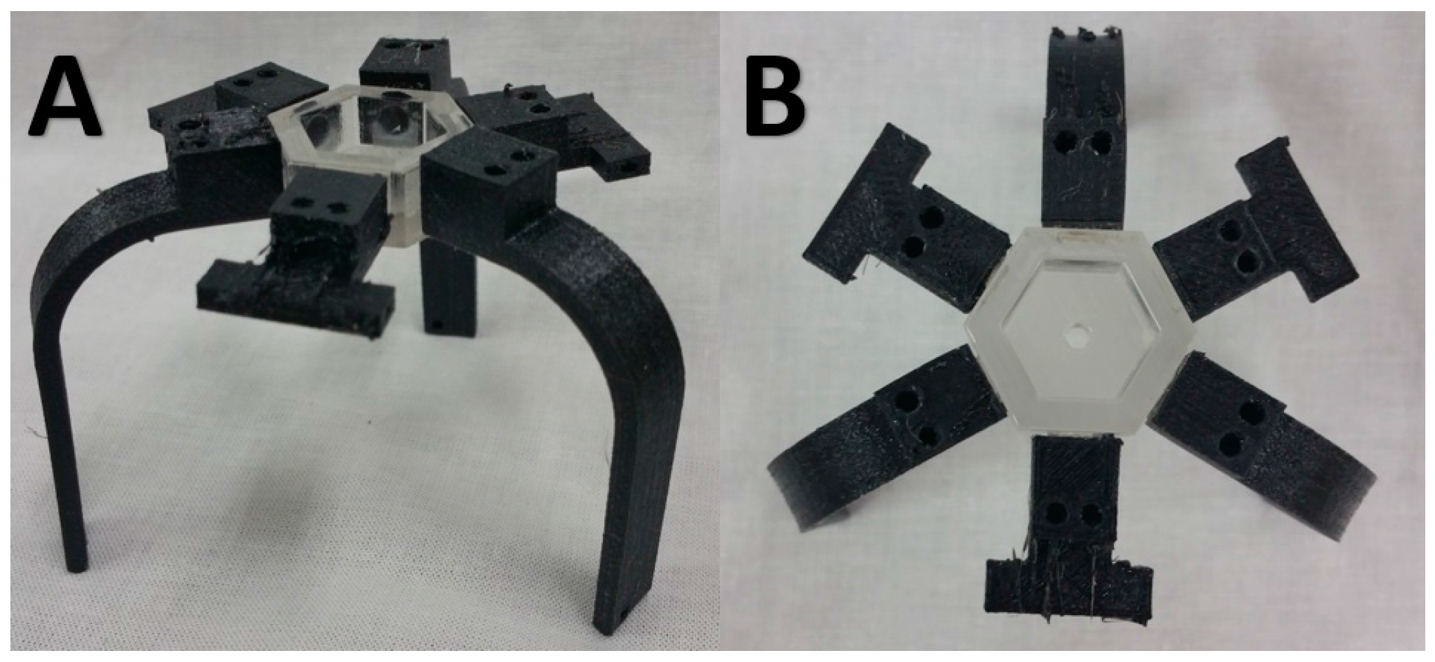
Figure 2.
Design of the air propelled limb and lateral thrusters where the arrows indicate direction of airflow: (A) wireframe model of the limb depicting the two channels running side by side; (B,C) cross sectional view showing airflow in each channel; and (D,E) isometric and plane view of lateral thruster showing the direction of air flow to generate rotation.
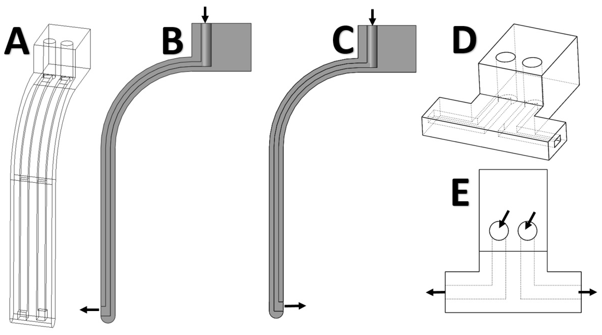
Figure 3.
Biomimetic gait locomotion achieved through air-propulsion: (A) extension of front limb to stride forward; (B) flexion of the back right limb; and (C) flexion of left back limb to complete one gait cycle.
Figure 3.
Biomimetic gait locomotion achieved through air-propulsion: (A) extension of front limb to stride forward; (B) flexion of the back right limb; and (C) flexion of left back limb to complete one gait cycle.

Figure 4.
Overall system architecture for the experimental setup.

Figure 5.
Finite Element Modeling (FEM) approach for bending of air-propelled curved beams.

Figure 6.
Experimental characterization of pneumatic actuator: (A) measurement of actuating force via load sensor; and (B) measured horizontal displacement during bending.
Figure 6.
Experimental characterization of pneumatic actuator: (A) measurement of actuating force via load sensor; and (B) measured horizontal displacement during bending.
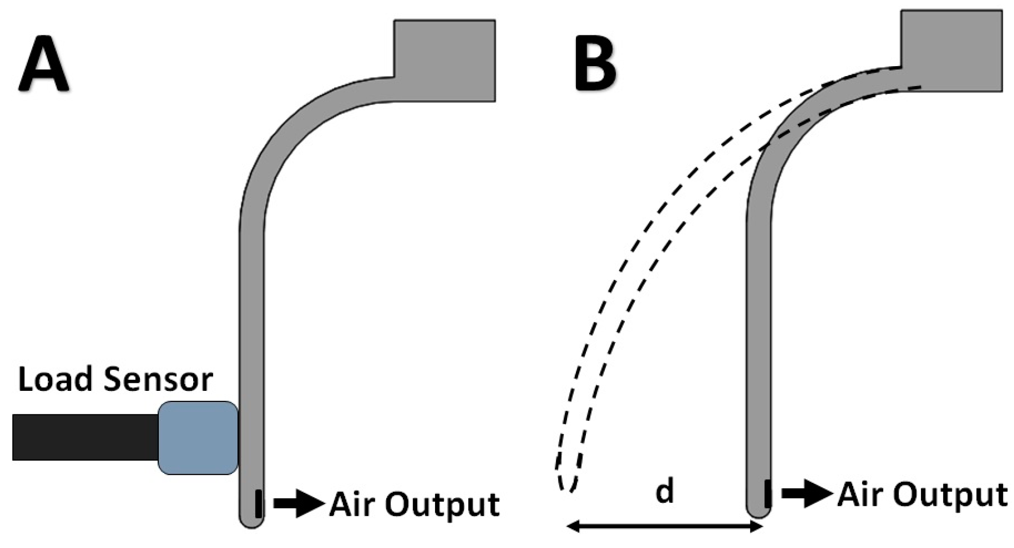
Figure 7.
Measured actuating force versus input pressure for square outlets of sides 2 mm and 3 mm.

Figure 8.
Finite element simulation of limb bending via COMSOL Multiphysics®. The color intensity denotes the relative displacement of the body from its initial resting state.
Figure 8.
Finite element simulation of limb bending via COMSOL Multiphysics®. The color intensity denotes the relative displacement of the body from its initial resting state.
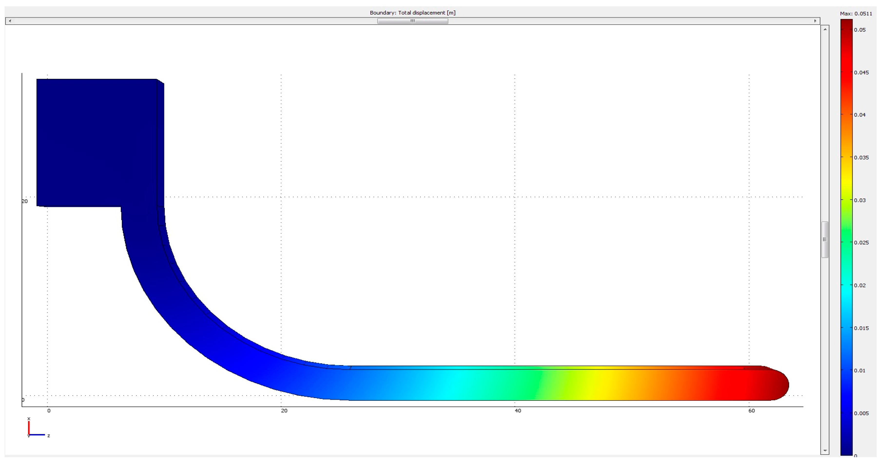
Figure 9.
Theoretical and experimental displacement against input pressure for different outlet widths. Error bars are indicated for experimental data.
Figure 9.
Theoretical and experimental displacement against input pressure for different outlet widths. Error bars are indicated for experimental data.

Figure 10.
Possible robotic motions: (A) grapping of plastic cup to lift it; (B) kicking of obstacles; and (C) picking of objects to place into a cup.
Figure 10.
Possible robotic motions: (A) grapping of plastic cup to lift it; (B) kicking of obstacles; and (C) picking of objects to place into a cup.

Table 1.
Bulk Material Properties of NinjaFlex®.
| Bulk Properties | Values |
|---|---|
| Bulk Density | 600 kg/m3 |
| Young’s Modulus [21] | 7.5 MPa |
| Compressive Modulus [21] | 20 MPa |
| Specific Gravity | 1.2 |
Table 2.
Qualitative Comparison of proposed actuation method with conventional pneumatic bladder actuators.
Table 2.
Qualitative Comparison of proposed actuation method with conventional pneumatic bladder actuators.
| Features | Air-Propelled Actuators | Pneumatic Bladder Actuators [34,35] |
|---|---|---|
| Speed of actuation | Very Fast | Moderately Fast |
| Hysteresis effect | Low | High |
| Force generated | Small | Moderate |
| Minimum wall thickness | Low | Moderate |
| Size to stiffness ratio | Large | Small |
© 2017 by the authors. Licensee MDPI, Basel, Switzerland. This article is an open access article distributed under the terms and conditions of the Creative Commons Attribution (CC BY) license (http://creativecommons.org/licenses/by/4.0/).
Share and Cite
MDPI and ACS Style
Chua, M.C.H.; Yeow, R.C.H. Propulsion-Based Soft Robotic Actuation. Robotics 2017, 6, 34. https://doi.org/10.3390/robotics6040034
AMA Style
Chua MCH, Yeow RCH. Propulsion-Based Soft Robotic Actuation. Robotics. 2017; 6(4):34. https://doi.org/10.3390/robotics6040034
Chicago/Turabian StyleChua, Matthew Chin Heng, and Raye Chen Hua Yeow. 2017. "Propulsion-Based Soft Robotic Actuation" Robotics 6, no. 4: 34. https://doi.org/10.3390/robotics6040034
Note that from the first issue of 2016, this journal uses article numbers instead of page numbers. See further details here.