1. Introduction
Nowadays, electronic equipment and computing devices are used in most types of industrial machines and robotic devices. They are key systems for the successful implementation of most industrial processes. However, the wide use of electronics makes this equipment more vulnerable to disturbances in terms of power quality (PQ). PQ is related to several disturbances that include, among others, momentary interruptions, voltage dips or sags, swells, transients, harmonic distortion, electrical noise, and flickering lights [
1]. In general, the electrical power grid is designed to deliver power reliably with the aim of maximizing the amount of power available to customers. However, PQ disturbances are not always taken into consideration despite the fact that they can significantly affect industrial production, as well as permanently damage expensive equipment, costing industrial plants millions of dollars [
2]. In order to minimize these costs, it is critical for industrial customers to understand how PQ can affect the operation of their systems and how it is possible to mitigate the effects of PQ disturbances [
1,
2,
3].
The international framework of the actual standards on PQ is based on the norms of the International Electro-technical Commission (IEC), which is accepted as a worldwide reference. Moreover, national or supranational committees give further indications on the maximum limits to be imposed on PQ disturbances. For example, the European Committee for Electrotechnical Standardization (CENELEC) is the European reference, while Comitato Elettrotecnico Italiano (CEI) is the Italian national reference for adopting IEC and CENELEC standards. The above-mentioned bodies have released the norm EN 50160 that defines the European and Italian standards for the PQ in terms of voltage dips and other voltage disturbances [
4]. Similarly, the norms EN 61000-4-11 and EN 61000-4-34 are adopted worldwide [
4,
5,
6,
7].
PQ is gaining significance also in robotics, and specifically in applications of service robotics. Voltage dips, also defined by the equivalent term voltage sags, are recognized as one of the most severe disturbances that can affect the operation of industrial devices. The detrimental effects of voltage dips can result both in the tripping of the protective devices with the equipment shut down and in the malfunction of a device. The latter constitutes a sort of failure that determines a far from normal or satisfactory functionality. Both these typologies of effects have significant economic impacts on a system’s operation and productivity. These costs depend on many factors that are linked to the type of manufacturing activity and to the extent of the affected area [
3].
Among other industrial devices, robots certainly suffer for the presence of voltage dips in the supply voltage. This is particularly critical in the case of collaborative robots which are penetrating several new applications also thanks to the publication of a collaborative robotics reference standard [
8]. In fact, the recent ISO (International Organization for Standardization) norm establishes a novel regulatory framework allowing a wide spread of collaborative robots in industrial and civil environments. The close interaction among robots and humans makes safety one of the most significant aspects of robot design and operation. Clearly, the effects of the voltage dips in the supply voltage can significantly influence robot performance as well as generate potentially critical safety issues, such as missing operations or unpredictable robot behaviors.
The case of robot grasping is quite significant, since the performance of an end-effector is considered to be the most important contribution to achieving the successful manipulation of an object. Several researchers have addressed the design of grasping devices with solutions ranging from simple end-effectors (suction cups, electromagnetic devices) to finger grippers for handling specific objects, and even complex multi-purpose robotic hands [
9,
10,
11,
12,
13]. It appears very significant to investigate the effects of power quality on a robot grasping, since a grasping failure implies a failure of the whole robotic manipulation procedure. Moreover, this can have strong safety implications, especially in collaborative robotics tasks, as mentioned in [
8].
This paper addresses the effects of the voltage dips on the performance of robotic grasping. A specific case of study is reported as referring to LARM Hand IV, a three-fingered robotic hand which has been designed and built at LARM at the University of Cassino [
14,
15,
16,
17]. A dedicated test rig has been designed and set up to generate predefined voltage dips to experimentally investigate their effect on the grasping of objects with different sizes. Experimental tests are carefully analysed and discussed to demonstrate the influence of the voltage dips on the grasping performance, as well as to propose some mitigation actions to avoid safety implications during the grasping.
2. Main Characteristics of the Voltage Dips
The term PQ embraces a wide set of disturbances that can affect the voltage and/or current [
3]. The disturbances are categorized in two groups: the variations and events [
4]. Each group represents a different type of phenomena and different ways of treating the disturbances [
5,
6]. The variations and events are due to the interaction between the power supply and the devices installed at the customers’ premises.
Variations are minor changes from the ideal value of voltage or current that show a relatively slow reduction in value. The level of variations can be measured continuously and at predefined instants of time. Examples of variations are the voltage amplitude variations and the waveform distortion. Events can have large deviations from the ideal value and they can occur suddenly. Events cannot be measured continuously because they may occur occasionally. A trigger condition is needed to measure these events. In the group of events affecting the supply voltage, voltage dips are one of the most severe disturbances that can affect especially industrial end-users. Several devices are significantly vulnerable to voltage dips. The main detrimental effects of the voltage dips are the tripping of protected devices and the degradation of the performance of a device.
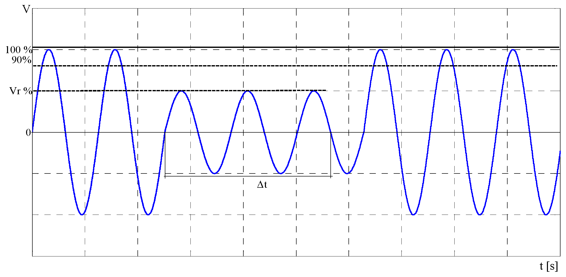
A voltage dip is defined as a “sudden reduction of the supply voltage, below 90% and above 1% of the declared voltage, followed by a voltage recovery after a short period of time” [
4].
Figure 1 plots the time of a voltage affected by a dip. In
Figure 1, the main characteristic quantities of a voltage dip are expressed as the amplitude with the symbol Vr, and the duration with the symbol ∆t as shown in
Figure 1. The amplitude of a voltage dip is the minimum value of the RMS voltage during an event; it is known also as the residual voltage. The duration of a voltage dip is the time elapsed when the voltage falls below the threshold value, which is assumed to be 90% of the rated value. Further quantities can characterize a voltage dip, like the number of involved phases, the phase angle jump, or the symmetry of the voltage dips on the phases.
In transmission and distribution systems, most voltage dips originate with the short circuits and further causes include the start of a large motor and the insertion of a large transformer, or of a high power load as can frequently happen in industrial systems. In the transmission and distribution systems, the dips more frequently originate with short circuits in some nodes of the electrical network. In the presence of a symmetrical solid short circuit in a specific node, two main phenomena happen. In the node where the short circuit occurs, the voltage is equal to zero and in the other nodes electrically close to it, the voltage is affected by the sudden reduction that represents a voltage dip. This phenomenon lasts until the protection device clears the short circuit.
The framework of the actual standards on the limits of voltage dips is mainly referred to the IEC and the CENELEC norms. In particular, IEC 6100-4-11 [
7] states the immunity test for the devices to define its operation class with reference to the EMC (Electro Magnetic Compatibility) and two main classes are defined which are the Class II and the Class III. The main standard of the CENELEC is the EN50160 that indicates the voltage characteristics of the electricity supply by public distribution network. In particular, for the voltage dips, this standard proposes the table shown in
Table 1 to classify them according to residual voltage and duration.
Table 1 refers to all the voltage dips that can be recorded in a node. It allows for immediately ascertaining the performance of a node in a considered period, typically at least one year. Actually, the trends of future standardization activities on the voltage dips are towards a limitation of the number of voltage dips that can be tolerated at any node of a system in a defined time period as the year. The limits could be expressed using a table similar to that in
Table 1. In such a case, any number of cells would express the boundary of the performance of the power supply that any customer should expect. Summarizing, the most important characteristics of a voltage dip are the amplitude and the duration.
3. Main Features of LARM Hand IV
Several designs have been developed for LARM Hand at LARM in Cassino, as detailed for example in [
14,
15,
16,
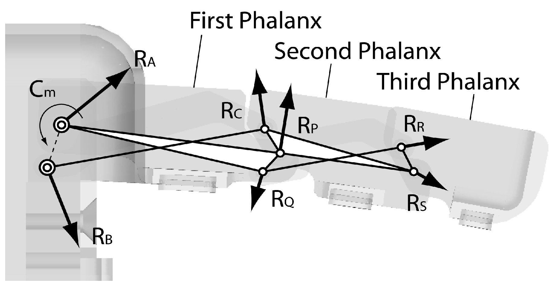
17]. The LARM Hand prototypes have three one-DOF (Degree of Freedom) human-like fingers. Their main features are low-cost design and easy operation. Only one motor is needed to drive each finger. Its torque is applied to the first link of its driving mechanism as indicated in
Figure 2 with C
m. One of the most complex design issues for LARM Hand has been the design of a suitable driving mechanism that can be embedded in the finger body and remains within the finger body also during its movement, as shown in the scheme of
Figure 2. This patented linkage-based driving mechanism of LARM Hand is described in full detail in references [
14,
15,
16,
17].
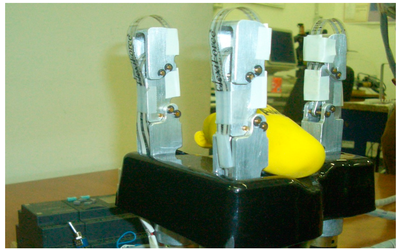
The LARM Hand IV, shown in
Figure 3, is equipped with three force sensors on each finger for measuring the grasping force on each phalanx while its operation is achieved by means of a low-cost PLC, which directly drives the three DC motors. A simple control logic is achieved by using a reference force threshold and by limiting the motor input current as it is directly linked with the motor output torque. It is worth noting that a firm grasp is achieved when all forces are in equilibrium. Therefore, the input torque has to be regulated to ensure a firm grasp as function of several parameters including the external force acting on the object, and the position, size, and shape of the grasped object. In this paper, we investigate how voltage dips influence the grasping of an object while using LARM Hand IV.
5. The Proposed Testing Procedure
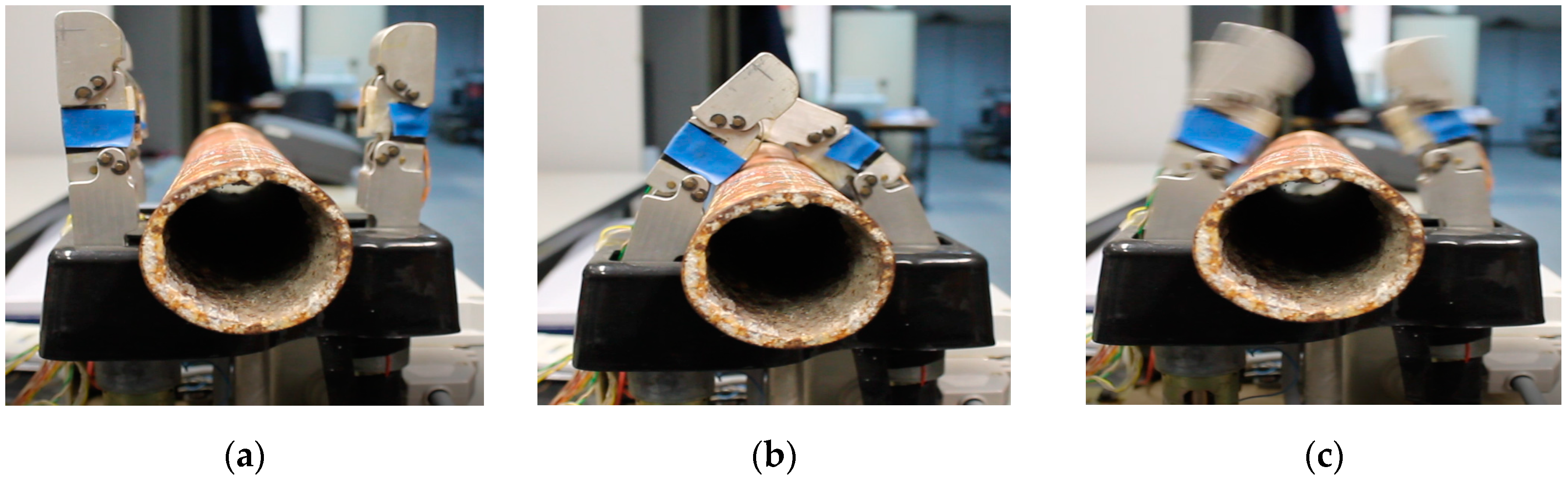
The built test rig is used to perform a set of experimental tests that have been selected for describing the most significant cases that can occur in the event of a voltage dip. For each test the LARM hand is set to start at an open position of the three fingers, and after about 5 s the LARM hand starts a phase with a closing operation of all fingers. This phase ends with the grasping of an object. As soon as contact is established between the object and fingers, the force sensors convert the grasping force into a voltage signal. The last phase consists of the opening of all fingers.
Figure 5 shows a photo sequence of the testing phases where
Figure 5a is the starting phase with fingers fully open;
Figure 5b is showing the closing phase;
Figure 5c shows the phase in which fingers are in contact with the object. The letters reported in
Figure 6 and
Table 2 summarize the effects on the most significant cases that can occur. Plots of the experimental tests are then reported for each case to demonstrate what is the corresponding effect on the grasping.
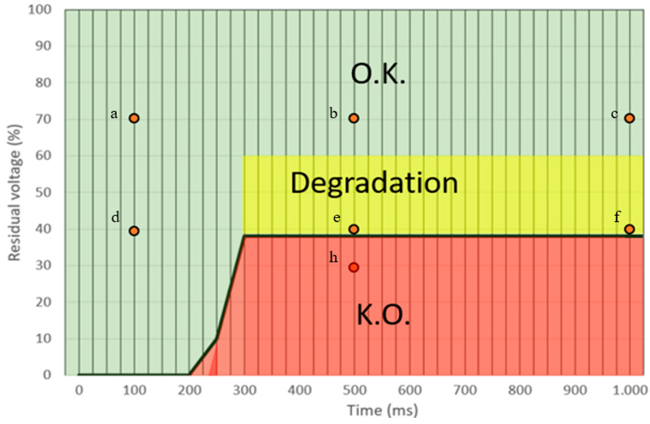
A first set of experimental tests can be defined as vulnerability tests. They are aimed at identifying the vulnerability curve as reported in
Figure 6. In particular, the vulnerability curve reports the level of voltage supply conditions that are critical for the operation of LARM Hand. Namely, the vulnerability curve in
Figure 6 identifies a set of voltage supply conditions in which the LARM hand is not able to run properly due to a voltage dip. It is worth noting the vulnerability depends on the combination of the duration of the voltage dip and the residual voltage percentage. For example, a voltage dip of 250 ms will prevent the successful operation of LARM hand if the residual voltage is less than 10%. But, a voltage dip of 250 ms will not produce any effect on the operation of LARM Hand if the residual voltage is higher than 10%. Similarly, a voltage dip of 300 ms will prevent the successful operation of LARM hand if the residual voltage is less than 38%. However, a voltage dip of 250 ms will not produce any effect on the operation of LARM Hand if the residual voltage is higher than 38%. In other words: any voltage dip, whose characteristics (residual voltage percentage and duration in ms) are below the vulnerability curve is a K.O. condition for the system; otherwise, any voltage dip whose characteristics are below the vulnerability curve is an O.K. condition for the system. It is important to note that there is a region close to the vulnerability curve where the LARM hand will be running, but a degradation of performance can be expected. The precision in identifying the O.K. and K.O. areas can be assumed to be comparable with the accuracy of sensors (1% Full Scale). After the above-mentioned vulnerability tests, specific tests have been carried out with the LARM hand by considering operation conditions being close to the vulnerability curve. The following aspects have been considered as performance parameters for the behavior of LARM Hand during voltage dips:
- (1)
Absorbed current by LARM hand;
- (2)
Tension output from the force sensor.
The tests that have been carried out can be divided into two main cases:
The type A case has been investigated to obtain the nominal performance of the LARM hand in order to have reference nominal output data. The type B cases aims to evaluate the effect of voltage dips on the grasping performance of LARM Hand. In particular, type B cases have been investigated by considering the voltage dip cases, which are reported in
Table 2. Results of type A and type B cases are reported in the following section.
6. Testing Results
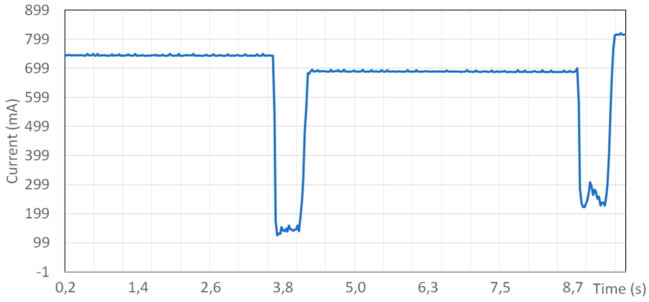
A first set of experimental results refers to the nominal performance of LARM hand as defined in the type A testing case in the previous section. In particular, it has been possible to collect the current absorbed by LARM Hand in nominal conditions as reported in the plot of
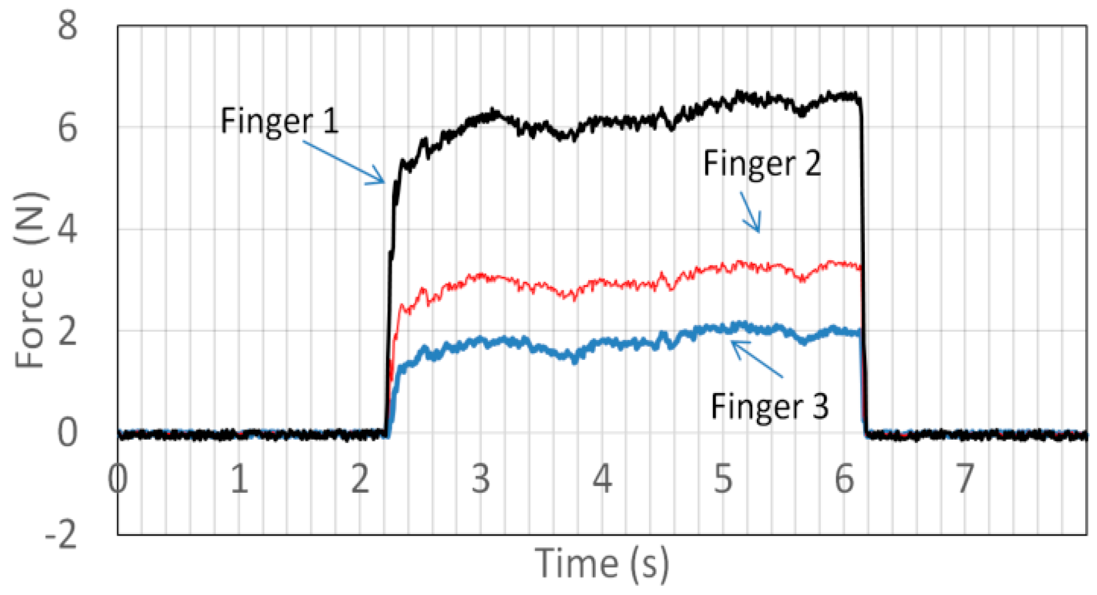
Figure 7. Moreover, the output grasping force has been obtained as measured by the force sensors on each finger of LARM hand in nominal conditions as shown in
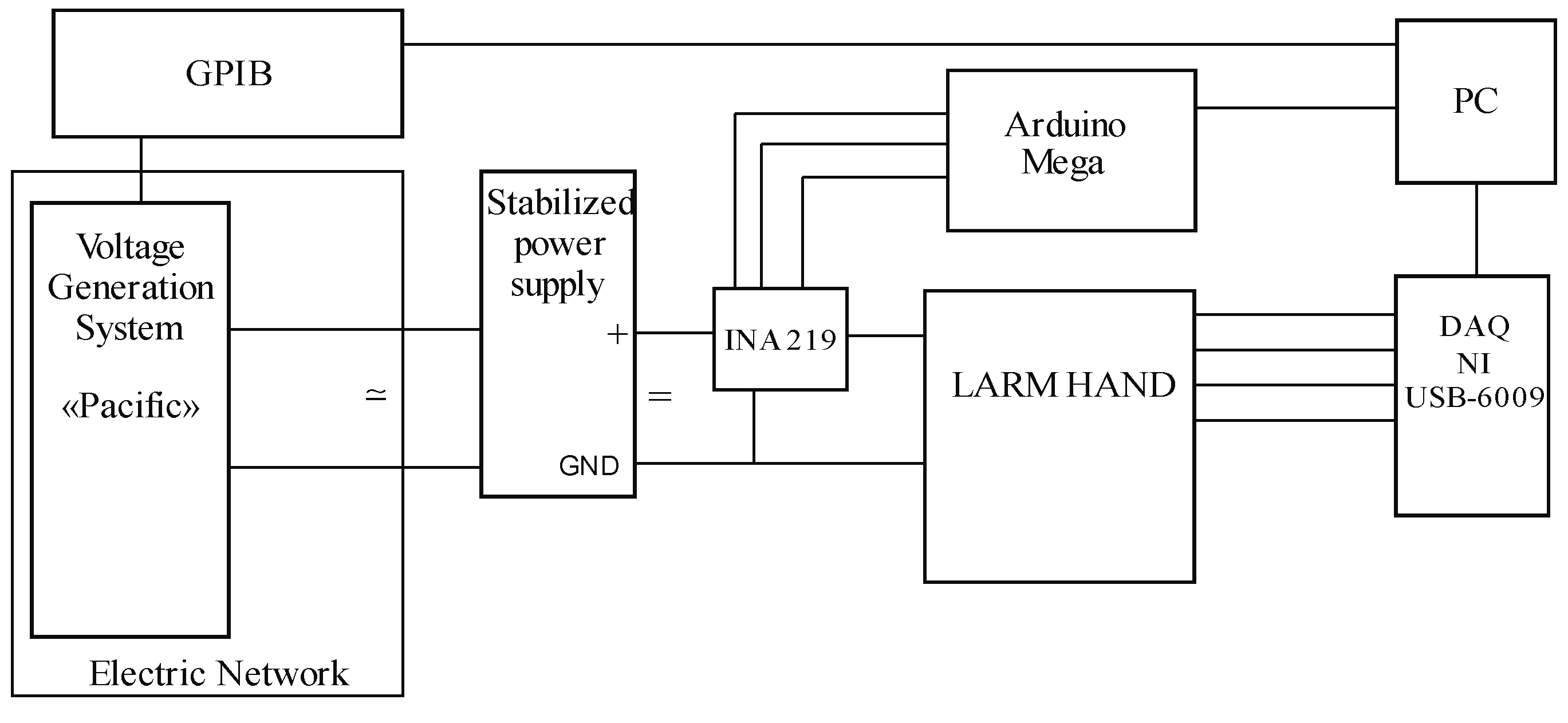
Figure 8. The experimental data in
Figure 7 and
Figure 8 are collected by using two different data acquisition boards, as shown in the scheme of
Figure 4. The data sampling is synchronized using a common trigger while different sampling rates have been selected according to the different characteristics of the collected data.
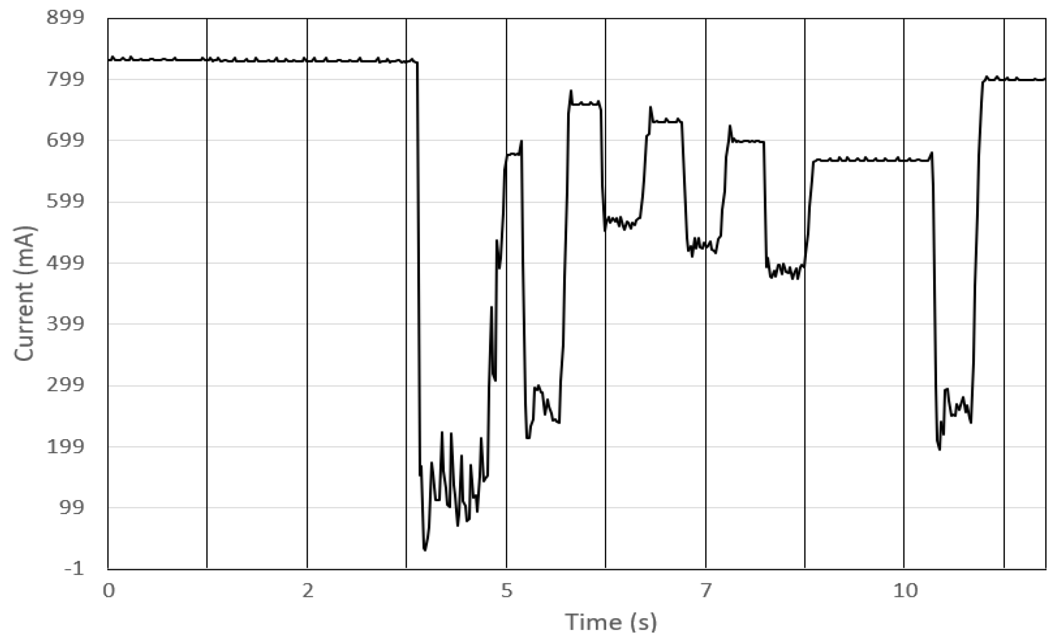
Referring to
Figure 7 it is possible to observe that in the first line segment the current value absorbed from the system has an average value of 750 mA. The current negative peak occurs in relation with the closing operation. This operation ends with a stabilized current value (660 mA) allowing a firm grasp. It is of note that a firm grasp is defined in terms a static equilibrium of the grasped object with no relative motion with respect to the fingers in contact with the object. The time period is identified from the experimental data by identifying the grasping force changes and getting the corresponding time interval. From the collected data the closing operation lasts for 531 ms corresponding to the time needed to reach about 6 N from 0 N.
Moreover,
Figure 8 shows that the measured grasping forces are all zero until the finger touch the object during the grasping. Then, the grasping force quickly grows until a firm grasp is achieved. At this time oscillations of the grasping force are measured due to small motions of the object as well as due to small changes in the contact point between the object and the sensors as well as small joint clearances on LARM Hand. Additionally,
Figure 8 shows that the measured grasping forces on finger 2 and finger 3 are similar to each other while the grasping force on finger 1 is nearly twice as much as on finger 2 or finger 3. This is due to the design of LARM hand where finger 1 is placed opposite to both finger 2 and finger 3 so that it needs to apply twice as much force to balance the combined forces due to finger 2 and finger 3.
The following set of experiments refer to cases a, b, and c in
Table 2 where voltages dips with residual tension of 70% have been considered. For these cases, any duration of the voltage dip did not generate an appreciable variation on the grasping performance of LARM Hand. Given the similar performance of cases a, b, and c in
Table 2, only case c is reported here. This case refers to a voltage dip with residual voltage of 70% and duration of 1000 ms. The measured plots for this case are reported in
Figure 9 and
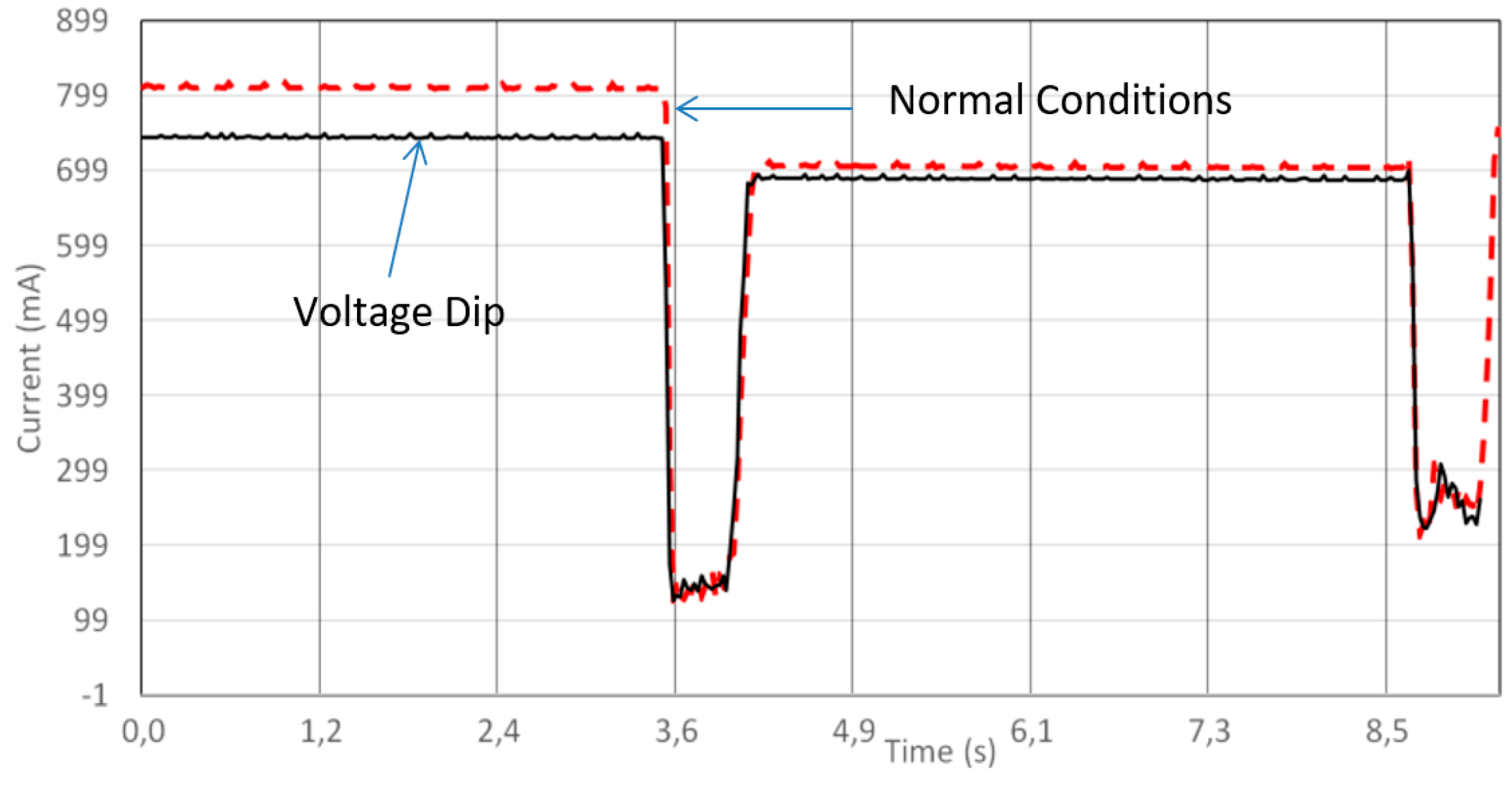
Figure 10. In particular,
Figure 9 shows a comparison of the current absorbed by LARM Hand in nominal conditions and during a voltage dip of 70% and duration of 1000 ms.
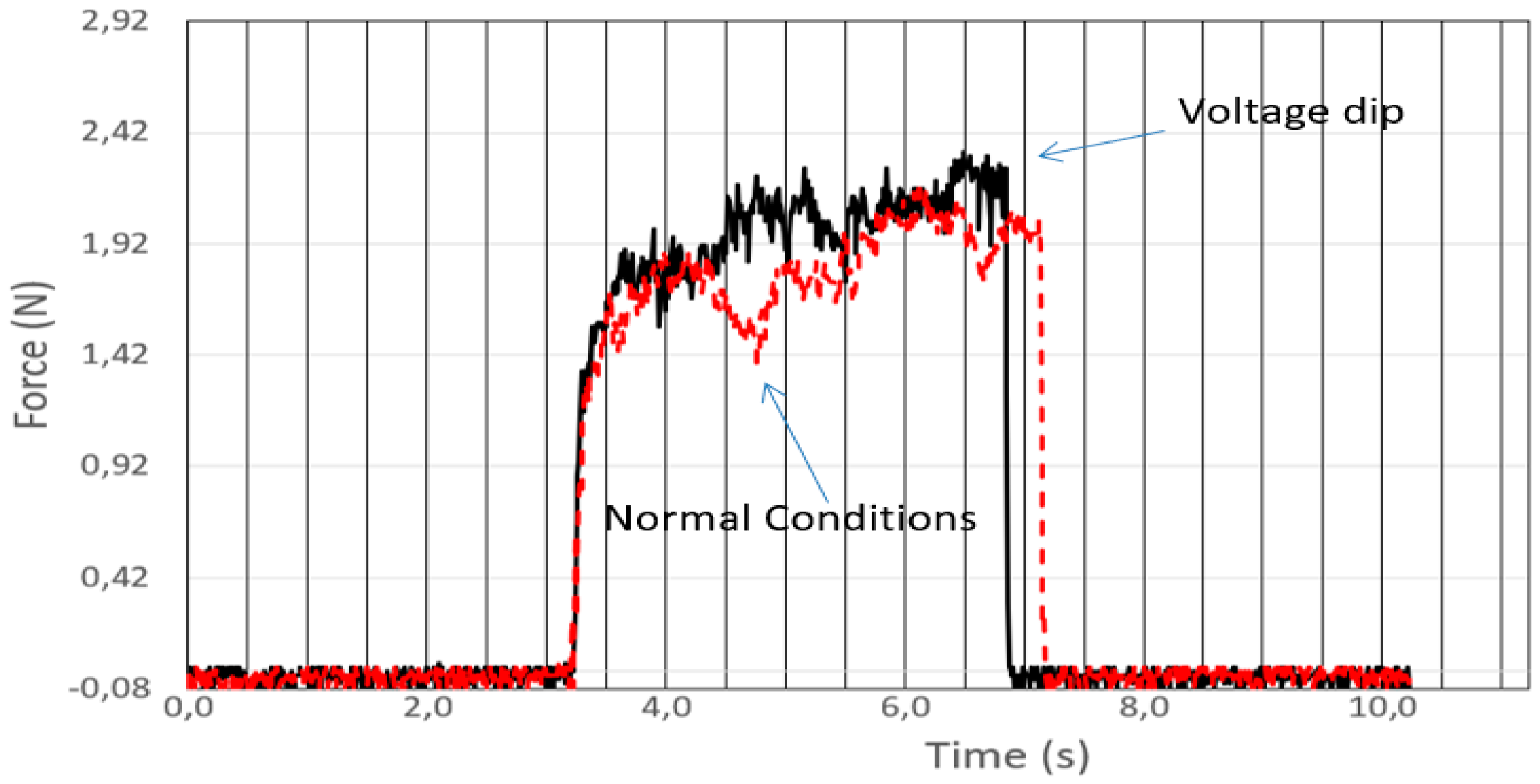
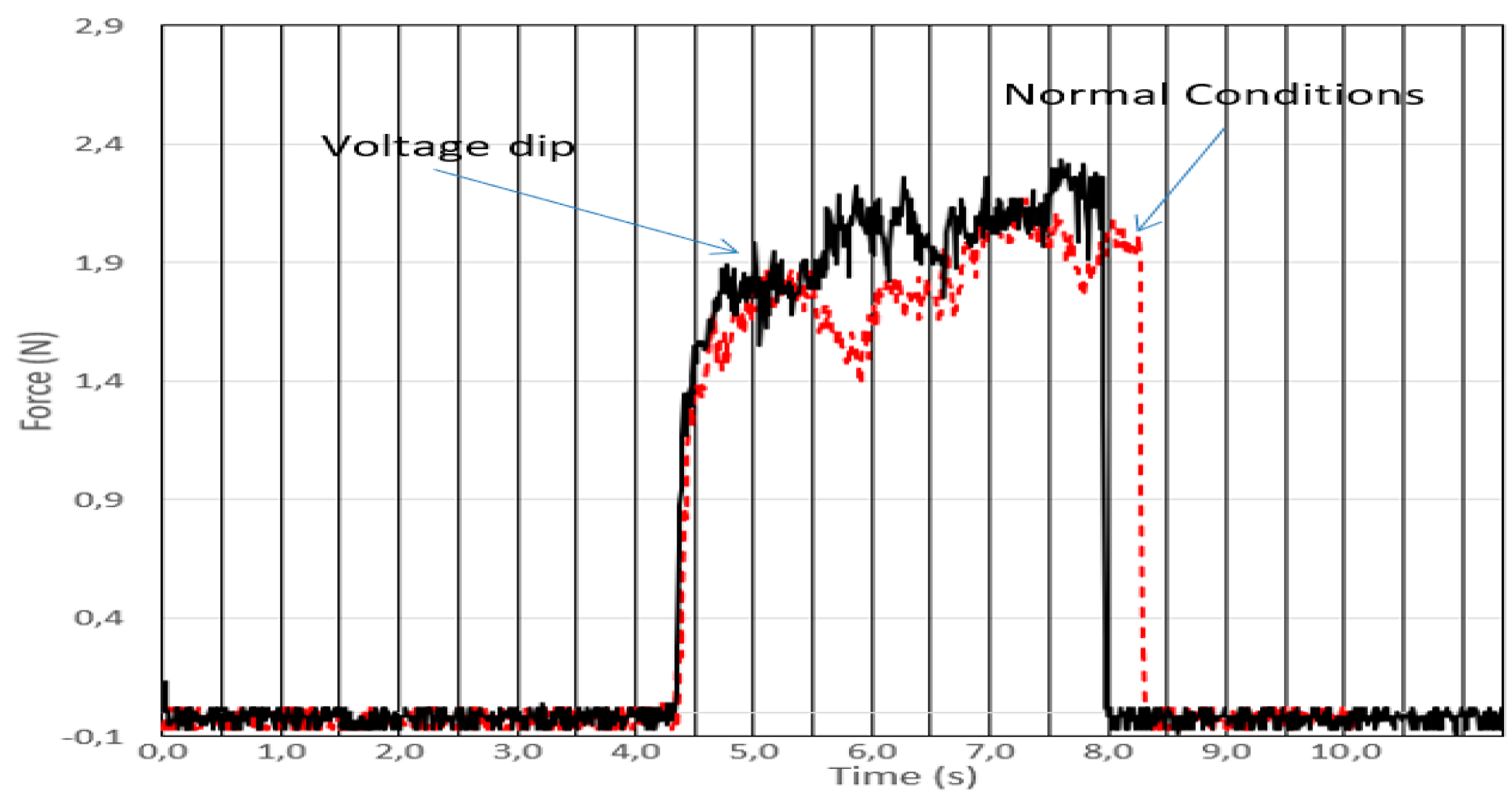
Figure 10 shows a comparison of one of the measured grasping forces by LARM Hand in nominal conditions and during a voltage dip of 70% with duration of 1000 ms. No significant differences can be identified in this case.
The tests with voltage dip with residual tension of 40% and duration of 100 ms (case d in
Table 2) have not shown any significant difference as compared with cases a, b, and c. Therefore, the related plots have not been reported in this paper.
The next considered case refers to a voltage dip with residual tension of 40% and duration of 500 ms (case e in
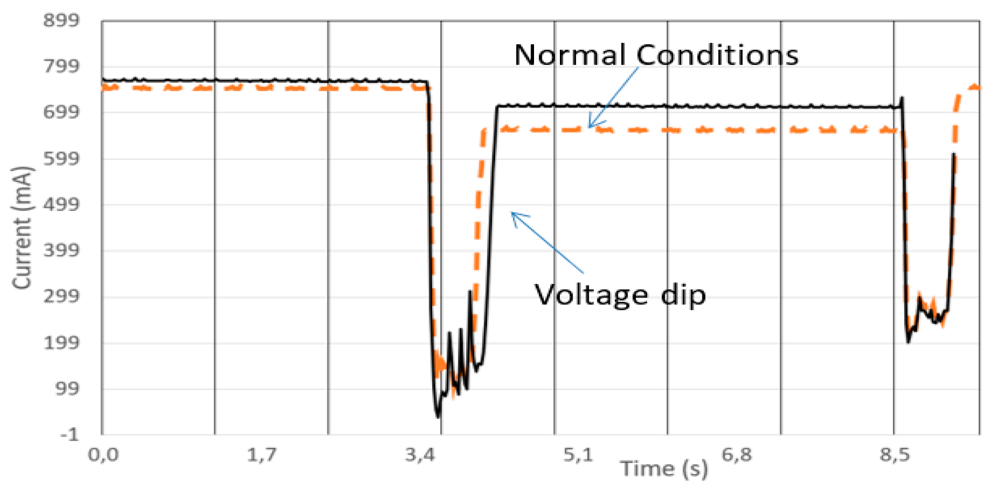
Table 2). In
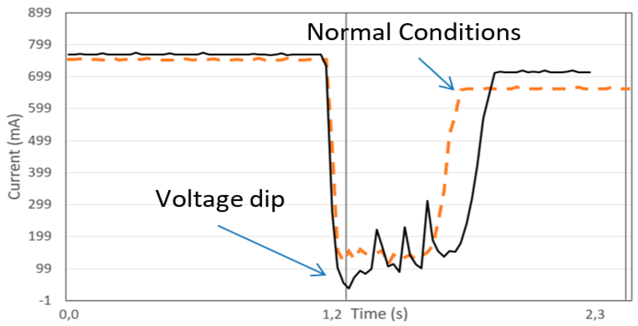
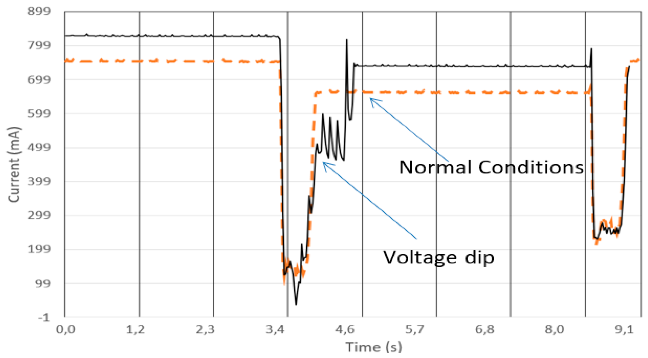
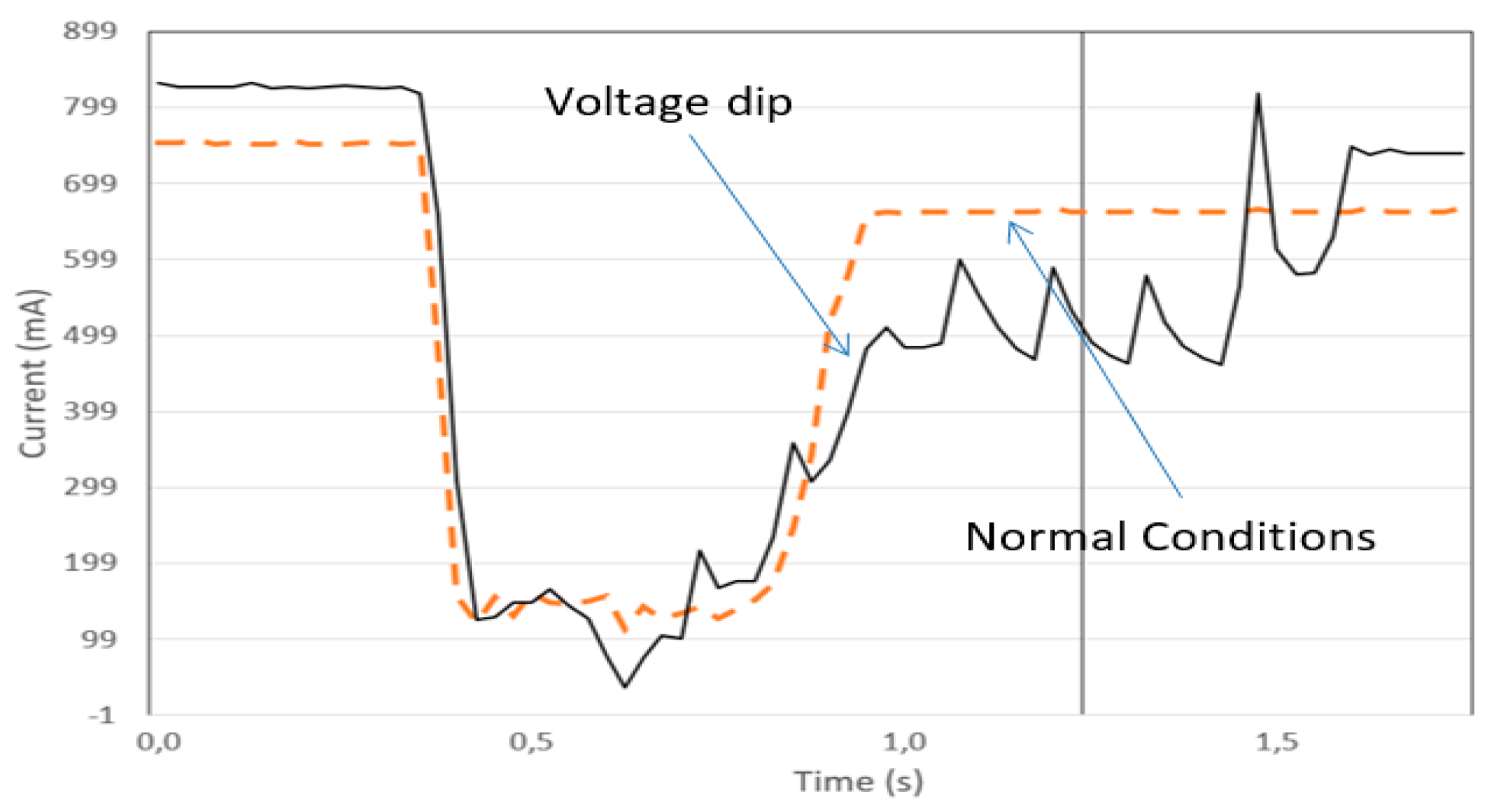
Figure 11 it is possible to note the effect that this type of voltage dip has on the current absorbed by the LARM Hand. This result is even clearer in the zoomed view that is shown in
Figure 12, where the finger closing operation phase is shown. In particular, it is possible to identify in this plot a heavy ripple current. This ripple causes a significant degradation of the grasping performance, introducing a relevant delay in achieving the grasp. The produced grasping delay is longer than the duration of the voltage dip as the system takes some time to recover from the voltage dip and to go back to nominal operation conditions. The plot of the grasping force that is reported in
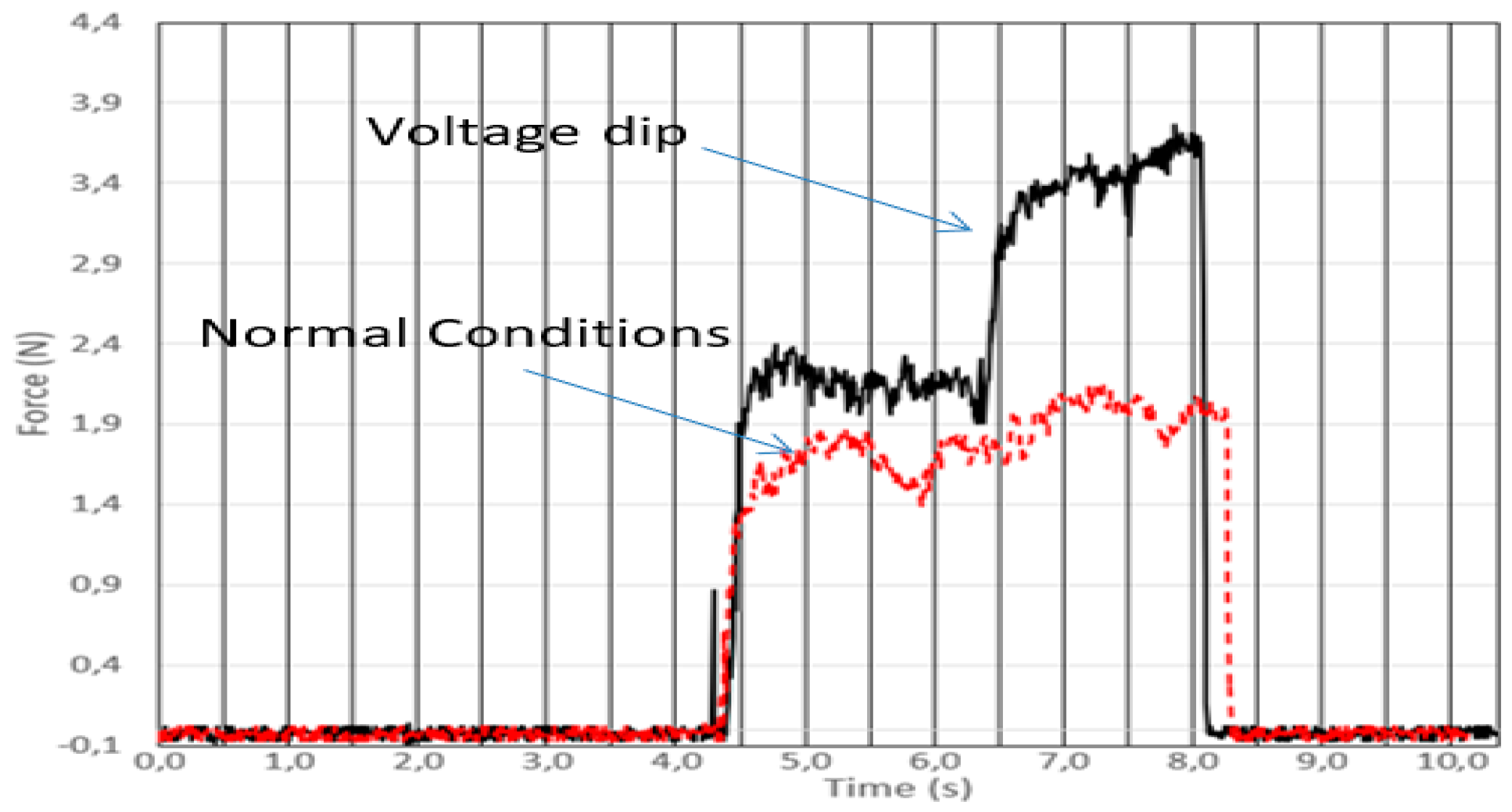
Figure 13 shows clearly the effect of the measured current. In fact, the comparison between the measured forces with voltage dip and in nominal conditions shows a very significant change of the grasping force in terms of a step in the grasping force that significantly affects the achievement of a firm grasp. The first contact between the finger and the grasped object shows a similar value of grasping force, but after the voltage dip ends the system starts to get more current and this causes a grasping force increase on the object with the need of achieving a new grasping equilibrium condition and a higher risk of losing the firm grasp of the object, as indicated by the increase of the grasping force after the voltage dip.
The next considered case refers to a voltage dip with residual tension of 40% and duration of 1000 ms (case f in
Table 2). In
Figure 14 it is possible to note the effect that this type of voltage dip has on the current absorbed by the LARM Hand, which is similar to case e in
Table 2.
Figure 15 shows a zoomed view of
Figure 14 by referring to the finger closing operation phase. In this plot there is a significant current ripple causing a significant degradation of the grasping performance and introducing a relevant delay in achieving the grasping. The produced grasping delay is significantly longer than the duration of the voltage dip, as the system takes some time to recover from the voltage dip and to go back to nominal operation conditions. The plot of the grasping force that is reported in
Figure 16 shows clearly the effect of the measured current. In fact, the comparison between the measured forces with voltage dip and in nominal conditions shows a very significant change of the grasping force in terms of a step and a delay of about 140% in the grasping force. This effect significantly affects the achievement of a firm grasp although this is smoother than the previously analyzed case e in
Table 2.
In the last case the voltage dip has such characteristics to fall fully below the vulnerability curve shown in
Figure 6. This is the heaviest voltage dip in terms of residual voltage, which has been experimentally tested with residual voltage of 30% and duration 500 ms (case h in
Table 2). The measured absorbed currents for this case are shown in
Figure 17. This plot shows the current absorbed by the LARM Hand is drastically modified as compared with the nominal case. The reason is that this voltage dip causes the re-initialization of the system and the release of the grasped object with a complete manipulation failure.
Results of the reported experimental tests prove the significant influence of voltage dips on the grasping performance. In particular, tests have identified four main cases:
Voltage dips above the vulnerability curve,
Figure 6, (residual tension between 90% and 70% of the nominal value and duration under 500 ms): They do not generate any significant degradation of the performance.
Voltage dips below the vulnerability curve,
Figure 6, (residual tension below 40% of the nominal value and duration above 400 ms): They generate a quite significant performance degradation with a temporary complete system shut down. This case is the most undesired one as the grasping/manipulation process is stopped with potential economic implications in an industrial production as well as potential safety implications if the grasping is performed during human-robot collaborative tasks.
Voltage dips close to the vulnerability curve shown in
Figure 6, (cases between the previous ones): In these cases, there is a progressive degradation of performances. The most evident effect is current ripple and a delay in current supply that is amplified in terms of evident delays and steps in the grasping forces that significantly affect the firm grasping as well as that can produce damages on grasped objects due to unexpected overloadings.
With voltage dip with 40% of residual voltage and duration of 500 ms cause a delay of the closing operation, which goes from the initial 531 ms in normal conditions to 700 ms, the closing time increasing by 40%. Even the absorbed current is affected by a big variation the maximum difference from the one in normal condition and the one in presence of voltage dip is 500 mA. Further, the grasping force suffers from sudden step variations in magnitude that can cause significant problems, especially while grasping very delicate objects.
The investigated operation of LARM hand can be considered as a case study offering some general rules. In particular, this gives insight on the significance and potential usage of the vulnerability curve for predicting and addressing the behavior of any robotic grasping device with respect to power quality.

 ,
, 


