A Tactile-Based Wire Manipulation System for Manufacturing Applications


1
Università di Bologna—DEI, Viale del Risorgimento 2, 40136 Bologna, Italy
2
Università degli Studi della Campania—DI, Via Roma 29, 81031 Aversa (CE), Italy
*
Author to whom correspondence should be addressed.
†
The authors contributed equally to this work.
Robotics 2019, 8(2), 46; https://doi.org/10.3390/robotics8020046
Submission received: 9 April 2019
/
Revised: 3 June 2019
/
Accepted: 10 June 2019
/
Published: 12 June 2019
(This article belongs to the Special Issue Advances in Italian Robotics)
Abstract
:This paper presents experimental results developed within the WIRES experiment, whose main objective is the robotized cabling of switchgears. This task is currently executed by human operators; the WIRES Project tackles the development of a suitably designed sensorized end effector for the wire precise manipulation. In particular, the developed gripper with tactile sensors are shown and a procedure for the implementation of the insertion task is presented and discussed. Experimental results are reported both for quality of wire shape reconstruction and success rate of insertion task implementation.
1. Introduction
Robotic manipulation is a complex task especially when deformable and fragile objects have to be grasped. In these cases, the knowledge of geometrical and physical characteristics of the object to manipulate are fundamental for the successful implementation of the task. To this aim, specific sensing systems are developed to be integrated into robotic systems. This paper presents results of activities developed within the WIRES experiment (http://www-lar.deis.unibo.it/people/gpalli/WIRES/), where the main objective is the robotized cabling of switchgears. Switchgears are basic components in a wide range of applications. Currently, the switchgear wiring is executed by human operators due to the complex manipulation tasks. The WIRES Project tackles the development of a suitably designed end effector equipped with a vision system and a tactile sensor for wire-precise manipulation. Preliminary results have been presented in [1,2,3].
Standard approaches to this kind of problem use vision and/or tactile data. Often vision is used alone due to its efficiency in data collection ([4]). However, this solution may fail in the presence of varying lighting conditions and occlusions. The use of tactile sensors helps to improve the success rate by overcoming some environment limitations. As a consequence, there have been many papers where vision and tactile data are integrated in a single approach ([5,6,7,8,9]. The objective of these approaches is the estimation of object characteristics, such as pose, shape, surface features and so on. Among these, some researchers propose interesting algorithms for edge detection [10] that could be considered in future as alternative approaches with respect to the one proposed here in order to improve the estimation quality. At the moment, the estimation quality reached with the approach proposed here is sufficiently high for the task implementation, with a very simple formalization. Some researchers in recent papers [11] use vision systems directly integrated into fingers to evaluate both tactile and image data at the same time and with the same sensing system. Also, this approach demonstrates how the fusion among tactile and vision data can be a good approaches for manipulation tasks. However, none of these past papers tackle the estimation problem of shape and pose of flexible objects like wires.
In previous papers [2,12], the authors presented details of the tactile sensor design and a possible use of tactile data for the reconstruction of the grasped wire shape and the use of the estimated shape for the implementation of an insertion task. In those papers, the model used for the wire was constituted by a quadratic function for the grasped area and a straight line for the part outside the tactile sensor pad. The sensor was mounted on a commercial gripper and preliminary insertion tests have been carried out on a single hole of an electric component fixed on the workbench, with the same wire grasped from a single position.
This paper presents improvements with respect to the previous system in terms of mechatronic solutions that are integrated and tested in a new scenario much closer to real cases. In particular, for this paper, the tactile sensor has been integrated into the final end-effector designed for the WIRES Project, presented and equipped with an electric screwdriver used to automatically complete the connection task. A simplified solution for the wire shape estimation is considered in order to allow its integration directly into the on-board microcontroller. This solution is a subset of that proposed in [12], but is explicitly formalized to be used with the final end-effector in the current study. The quality of the reconstruction has been re-evaluated with the new model, by redefining the quality metric according to the different model, in order to check if the considered simplification does not strongly affect the expected results. Finally, unlike previous papers, the whole system has been tested in a more complex scenario, by grasping, inserting and connecting a sequence of wires in a testing switchgear as shown in the video as supplementary.
2. The Tactile Sensor and the Gripper
The tactile sensor working principle and its design is detailed in [12]. Here, a brief recalling is reported (related to the integration in the gripper). Figure 1 reports some pictures of the developed sensor where the main components are highlighted. The 16 taxels constituted by the optoelectronic components with the deformable layer bonded above represents the transduction part for the sensor. The optical signals are converted in electric signals by using simple resistors and the obtained voltage signals are acquired with a standard Analogue-to-Digital converter. All details about the components integrated in the PCB are reported in [12]. For the integration into the gripper finger, a second PCB with a microcontroller has been developed and connected to the first one. The second PCB is completed by a voltage regulator and a standard connector, which allows to interface the tactile sensor with a standard USB-TTL serial cable. A suitably designed finger case has been realized in aluminum via a 3D printing technique and the extended PCB has been integrated inside this case. The thickness of the designed case is the smallest in order to allow the insertion of the finger among the switchgear components and wires already connected. The case allows a mechanical connection to the gripper by using two screw.
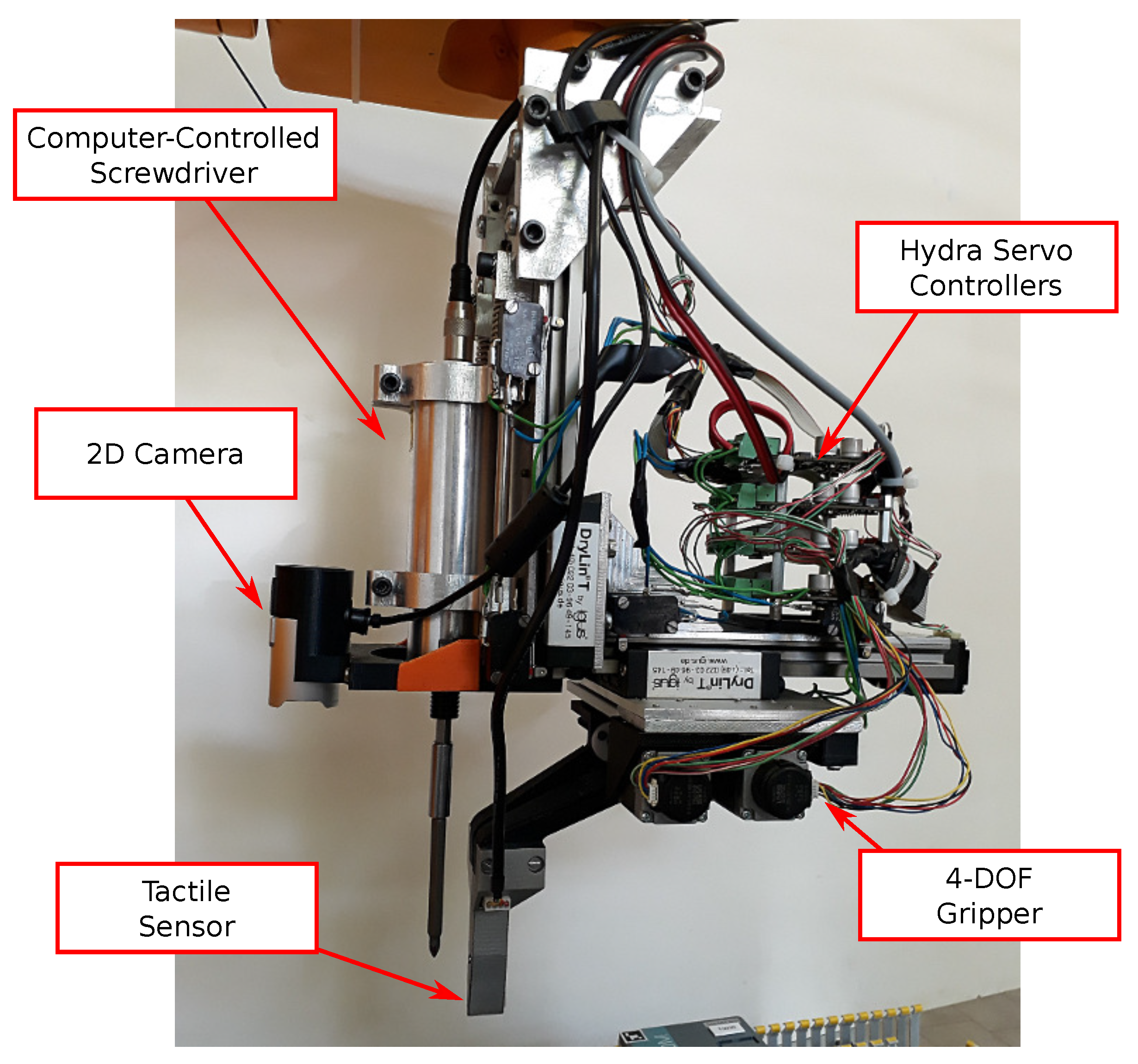
The end effector developed in the WIRES experiment for the implementation of the whole cabling process can be seen in Figure 2. The end effector integrates a 2D camera providing top view of the scene, an computer-controlled screwdriver (to tight the terminal screws) and a 4-DOFs gripper equipped with the tactile sensor. The end effector is also equipped with an integrated torque/controlled screwdriver with remote PLC control and process data recording capabilities (Kolver PLUTO3CA electric screwdriver + EDU2AE/TOP/E control unit). In the final process implementation, the robot arm is used to position the screwdriver tip on the terminal screw, and the FT sensor will be used to control the contact with the screw during the tightening. Therefore, the end effector will be held in an almost fixed position, just the screw motion during the tightening will be compensated. Consequently, the wire insertion will be performed by using the gripper DOFs only. It results that the FT sensor can be used to estimate the interaction between the screwdriver and the terminal screw, but it cannot be used during the insertion and for the wire tightening check, because the magnitude of the force generated by the wire contact is much lower than the one generated by the contact between the screwdriver and the screw, making the former indistinguishable. For this reason, the use of the tactile sensor installed into the gripper fingertips is fundamental also during the insertion and for the wire tightening check, in order to reach a suitable success rate.
Stepper motors with integrated encoder and lead screws have been adopted for the actuation of the end effector. This solution significantly simplifies the control and reduces the weight, the mechanical complexity and the cost of the end effector. Limit switches have been used for absolute position detection on both sides of all the end-effector movement axes. Each motor is driven by a Hydra servo drive control board, used as HW low-level motor controllers. These control boards are arranged on the end effector itself. The communication between the motor control boards and the high level WIRES controller is implemented through CAN bus. A ROS node has been developed to allow the control of the end effector and to ease the integration with other components of the WIRES system. At low level, the motors are controlled by means of the PLCOpen standard, allowing an easy implementation of the end effector controller. The tactile sensor has been integrated into the jaw tips (fingertips). Several versions of 3D printed fingers have been produced in order to evaluated different configurations during experiments.
3. Wire Shape Estimation
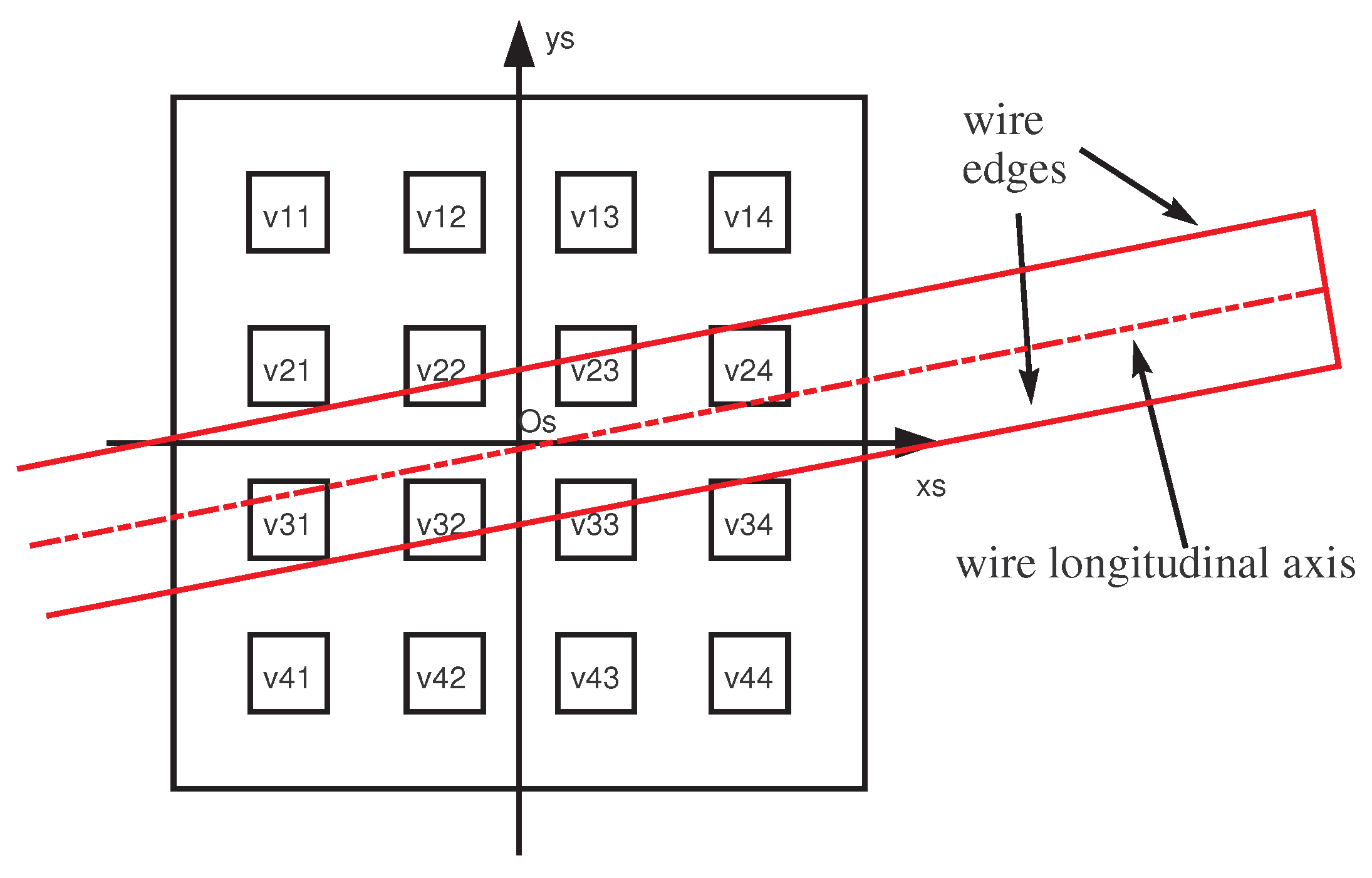
A specific sensor reference frame, , is defined at the center of the tactile sensor pad (see Figure 3) and the wire shape estimation problem is tackled with respect to this frame. The 16 taxels are organized as a matrix, where each cell can be identified by its row and column indices. Hence, for each cell it is possible to associate a couple of coordinates , corresponding to the physical distances of the cell mechanical center from the sensor frame origin. In particular, the x-coordinates of the columns are −4.5 mm, −1.5 mm, 1.5 mm and 4.5 mm, from left to right, while the y-coordinates of the rows, are 4.5 mm, 1.5 mm, −1.5 mm and −4.5 mm, from top to bottom. The measured voltage variation corresponding to the cell is indicated as .
In this paper, in order to estimate the shape of the grasped wire, this is locally approximated as a straight line, coincident with the longitudinal axis of the wire (see Figure 3), modelled in the frame as the line with equation
where m and n are the two parameters to be identified by using the tactile data. Since the section of the grasped wire is considered a priori known, estimating the grasped wire shape means to estimate the m and n parameters characterizing longitudinal axis of the wire. The initial position of the wire implies that the grasped wire has the main direction always mainly aligned with the -axis (horizontal direction). In this hypothesis, the procedure for the wire shape estimation is constituted by a first step, where the centroid coordinates for each column are computed, and a second step, where the computation of the model parameters in (1) is implemented via a least squares method applied to the data set constituted by the coordinates of the column centroids. In detail,
step 1:
the y coordinates of the column centroids are computed from tactile data as
where is the mechanical y coordinate of the i-th row. Hence, the data set is constituted by the coordinates of the 4 column centroids (where is the mechanical x coordinate of the j-th column).
step 2:
the model (1) parameters, m, n, are estimated by using a least squares method applied to the data set resulting from step 1.
The presented procedure has been experimentally applied by grasping a wire in different configurations. Figure 4 reports a generic grasp: the tactile map shows how the cells on the second and the third rows present higher values. The column centroids (green stars) have been computed by using Equation (2) and than the wire shape has been computed via least squares method (straight line). To assess the accuracy of the algorithm, a comparison among the estimated shapes and the actual ones has been carried out, superimposing a picture of the corresponding grasp to the measured data and estimated shapes. Figure 5 shows the good matching between the estimated and the actual wire shapes. The quality of the shape reconstruction is fundamental to successfully complete the insertion task, as detailed below.
4. The Insertion Task
As discussed in Section 1, the main objective of the WIRES project is the robotic assembly of electric switchgears. To this aim, a fundamental subtask is represented by the insertion of the wire into the holes corresponding to the pins of the electrical components. The successful execution of the task allows the mechanical connection of the wire. The tactile sensor has been integrated into the gripper, suitably designed for the WIRES project in order to experimentally test its funcionalities during the insertion task. The proposed solution for the insertion task described in the following is based on the assumptions that the relative position between the robot system and the switchgear is known and, additionally, the length of the protruding part of the grasped wire is also known. Note that in real applications, a standard calibration procedure for the robot system allows us to obtain a precision that satisfies the first assumption. For the second assumption, the length of the protruding part of the wire can be estimated by using the camera integrated into the gripper as described in Section 2.
A human operator prepares the wire by placing it in a delimited area (based on the gripper stroke), with a random pose. The robotic system is used to grasp the wire and as a consequence, after grasping, the pose of the wire with respect to the tactile sensor is unknown. Then, the grasped wire shape is estimated by computing the model parameters m, n and applying the wire shape estimation algorithm. Figure 6a reports a sketch of a generic grasped wire, with the estimated shape. Let be the hole frame, with the origin in the center of the hole and the -axis aligned with the hole axis; let be the wire end frame, with the origin in the end point of the wire actual axis and the -axis aligned with the wire actual axis; let the frame , with the origin in the end point of the estimated wire axis and the -axis aligned with the estimated wire axis. On the basis of the assumption described above, the poses of and are perfectly known, while the pose of can be computed from the estimated shape parameters m, n and the protruding part L value of the grasped wire. To this aim, the homogenous transformation matrix can be computed from Figure 6a with simple geometrical considerations
where and (a is the half side length of the sensor pad). After the computation of , a standard technique can be used to program the robotic system in order to align with . After that, the resulting configuration is sketched in Figure 6b, with . From this point the insertion task can be easily completed with a linear movement along the -axis. In real working conditions the hole diameter D is typically two times larger than the wire diameter d. Note that in this paper, the insertion has been tackled by considering the task a 2D problem; the z-axes are considered all aligned.
5. Assessment of Wire Shape Estimation and Expected Success Rate
In ideal conditions, when the estimation error of the wire shape is zero (i.e., ), under the described assumptions, the proposed procedure allows us to align the wire axis and the hole axis, by maintaining the distances between wire and hole edges (both above and below ) equal to the maximum possible value . Obviously, in this case, the execution of the insertion task is guaranteed with a Success Rate . In real working conditions, the estimation error of the wire shape implies , and since the alignment can be made only between and , when the estimation error increases the insertion task may fail. As a consequence, in real conditions the success rate of the insertion task is .
The quality of the estimated grasped wire shape and the maximum SR reachable can be evaluated taking into account both the estimation error and the actual diameters of the hole and the wire. In particular, the estimation error can be quantified by considering the relative poses of and . The relative pose of these two frames can be represented by the following homogeneous transformation
where is the angle between the estimated wire axis and the actual one, while is the distance between the origins of and . In the ideal case, with a perfect shape estimation it is and . In real working conditions (), after the alignment (see Figure 6b), the distances between wire and hole edges depends on and . In particular, the estimation error implies that the actual position of the wire presents an offset along -axis, which is responsible for any failure in the execution of the insertion task. This offset, computed from , is equal to and it reduces the space between wire and hole edges. The maximum limit for this offset, in order to avoid the unsuccessful execution of the task, is represented by the value . As a consequence, the following metric
can be computed to evaluate both the quality of the grasping and the expected result (success or not) of the insertion task execution. In conclusion, if the insertion can be successfully completed, while if the insertion task cannot be correctly completed. Moreover, the more is close to , i.e., , the better is the quality of the estimated wire shape.
6. Experiments
A number of experiments have been carried out to evaluate the proposed approach. For each experiment, the wire shape has been computed according to the procedure detailed in Section 3. Tens of static experiments, with the sensor fixed on the workbench, have been used to evaluate the shape estimation quality and expected success rate. Additional experiments have been carried out to evaluate the actual success rate of the insertion task in real working conditions, by using the sensorized gripper with standard wires and electrical component.
6.1. Estimation Quality and Expected SR
For the first set of experiments, a standard wire with mm has been grasped between the tactile sensor, fixed on the workbench, and a transparent methacrylate plate, in different poses. By considering the diameter of the hole of the electric component , it is mm. A calibrated optical microscope has been used to take pictures from the transparent plate side. Hence, the offset errors between the estimated and the actual wire end points can be directly measured from the pictures. Figure 7 reports two sample cases, where the estimated wire shapes are compared to the actual ones. For each considered case the value of the offset error is reported. By using Equation (5) the metric can be computed, obtaining for the cases in Figure 7 the following values: mm for case (a) and mm for case (b). From these values it is evident that case (a) allows the correct execution of the insertion task, while case (b) does not guarantee a correct insertion phase (). Note that case (b) corresponds to a grasp configuration close to the diagonal of the sensor pad (that is quite unlikely). The same procedure has been applied to 20 considered experiments. Finally, all grasping cases have been divided into two sets: the first set corresponding to cases with a computed metric (17 experiments) and a second set with (3 experiments). The expected success rate for the insertion task has been computed, by relating the number of experiments within the first set with respect to the total number of experiments, by obtaining a .
6.2. The Insertion Task Implementation
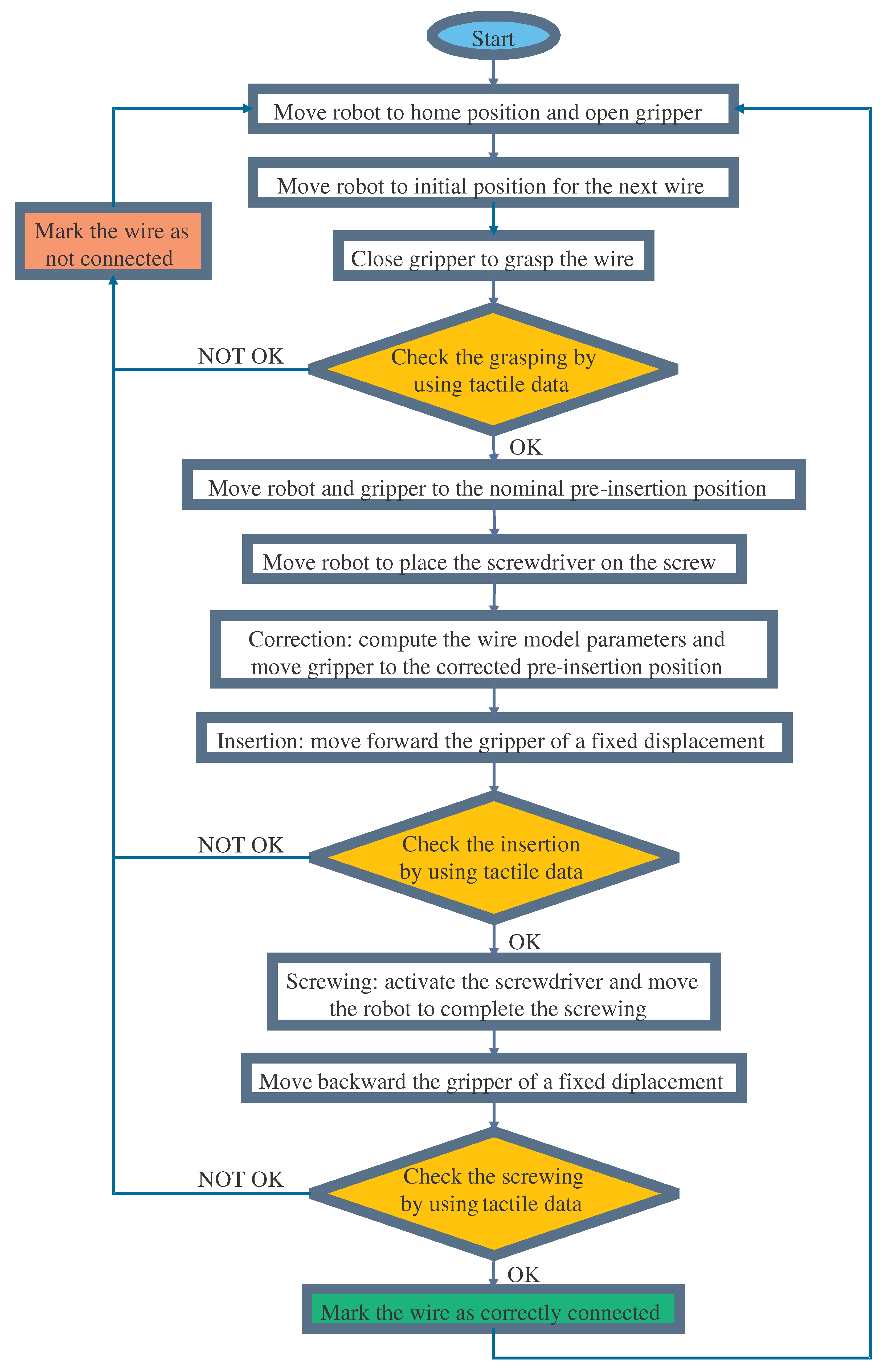
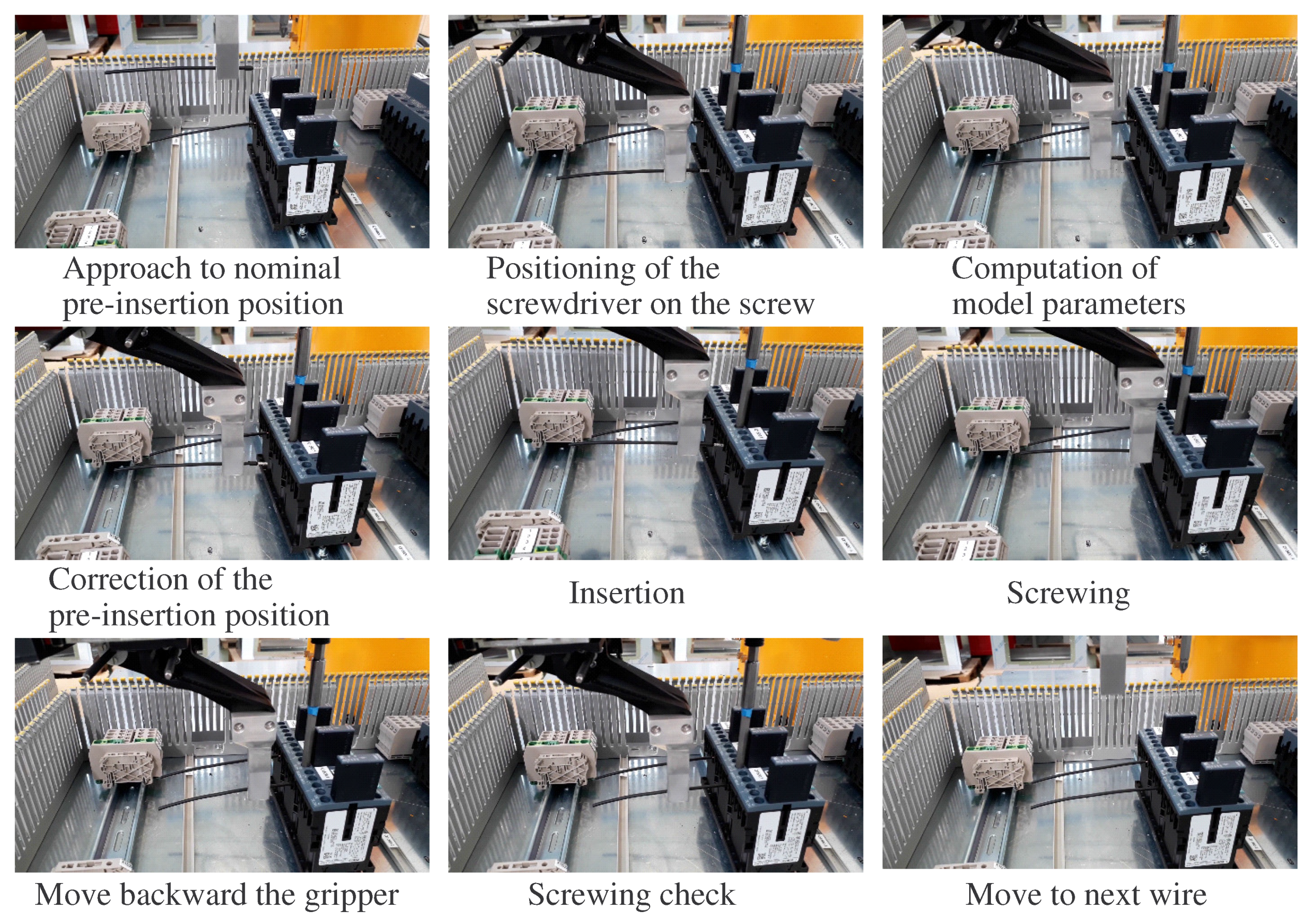
For the implementation of the insertion task, the sensorized gripper has been used. All measurements are reported with respect to the world reference frame , placed at the robot base. Position and orientation of with respect to is known in each time instant, by using the robot system kinematics. The pose of the electric component hole is defined by , assumed known from the switchgear CAD. Figure 8 reports experimental results for the s pose during an insertion task. After the wire grasping, the -axis is aligned to the -axis during an approaching phase (see Figure 8a), leaving a distance between and equal to mm in this specific case (it is the estimated length L plus the half side length a of the sensor pad). The reached configuration (at s) is reported in Figure 9a, where the estimated wire shape and the frame poses () are reported with respect to , together with the tactile sensor pad and the component hole. It is evident that without a correction the insertion cannot be completed correctly. The wire shape has been estimated by applying the wire shape estimation algorithm, and the parameters m and n have been used to compute the homogeneous transformation (3). For the experiment reported in the figures and . By using the computed homogeneous transformation, has been aligned with during the correction phase. Figure 8b shows a zoom of the rotation and the translation applied during the correction. After this phase, the estimated wire axis is aligned with the component hole axis. The reached configuration (at s) is reported in Figure 9b, where it is evident that the insertion can now be correctly completed with a simple translation along the x-axis. Figure 8a shows also the final insertion phase. Figure 10 reports the flowchart, where the connections among all subtasks of the whole insertion sequence are reported. Several checks are implemented by using the tactile sensor data during the insertion execution, in order to evaluate if the task is correctly completed or not. During experiments, the wire shape estimation error will affect the final success of the insertion phase. As discussed in Section 5, the actual wire end point is related to the frame, while the estimated wire end point is identified by the frame. To test how this estimation error affects the insertion phase during experiments in real working conditions, the insertion task has been repeated 40 times starting from different initial grasping conditions for the wire. The same experiment described above has been executed and, for each case, the final correct insertion has been evaluated. The number of successfully completed tasks was 33 with a success rate . The obtained SR is slightly below the expected SR computed in static conditions (see Section 5), as was foreseeable, since during the experiments, additional errors (e.g., robotic system calibration, electric component position) appears together with the wire shape estimation error. Figure 11 reports a sequence of frames extracted from the video (https://youtu.be/oPxkeeQLKi8) related to the paper in order to show how the designed gripper with the proposed approach allow to correctly complete an insertion sequence. Each frame has been marked with the corresponding procedure subtask. The video shows the effectiveness of the proposed approach during a demo. In the video, the robot is used to fix the screwdriver position for the connection, while the insertion is completely implemented by the designed gripper.
7. Conclusions
This paper presented a sensorized gripper for wire manipulation, and in particular, for their insertion into the electric components of a switchgear. The designed gripper integrates tactile sensors suitably optimized for this task. A specific procedure for the insertion task execution has been proposed and evaluated in terms of expected success rate. Experimental results have been reported to show the effectiveness of the proposed strategy. Future work will pprobably be devoted to using the sensor to estimate contact forces between the gripper and the manipulated wire during the whole assembly process of the switchgear.
Supplementary Materials
The following are available online at https://www.mdpi.com/2218-6581/8/2/46/s1.
Author Contributions
Design and development of the end-effector, G.P.; Design and development of the tactile sensor, S.P.; Integration, methodology and experimental validation, G.P. and S.P.
Funding
This work was supported by the European Commission’s Seventh Framework Programme (FP7/2007-20013) under Grant agreement NO. 601116 (ECHORD++—WIRES Experiment).
Conflicts of Interest
The authors declare no conflict of interest. The founding sponsors had no role in the design of the study; in the collection, analyses, or interpretation of data; in the writing of the manuscript, and in the decision to publish the results.
References
- Busi, M.; Cirillo, A.; De Gregorio, D.; Indovini, M.; De Maria, G.; Melchiorri, C.; Natale, C.; Palli, G.; Pirozzi, S. The WIRES Experiment: Tools and Strategies for Robotized Switchgear Cabling. Procedia Manuf. 2017, 11, 355–363. [Google Scholar] [CrossRef]
- Cirillo, A.; De Maria, G.; Natale, C.; Pirozzi, S. Design and Evaluation of Tactile Sensors for the Estimation of Grasped Wire Shape. In Proceedings of the IEEE International Conference on Advanced Intelligent Mechatronics, Munich, Germany, 3–7 July 2017; pp. 490–496. [Google Scholar]
- De Gregorio, D.; Zanella, R.; Palli, G.; Pirozzi, S.; Melchiorri, C. Integration of Robotic Vision and Tactile Sensing for Wire-Terminal Insertion Tasks. IEEE Trans. Autom. Sci. Eng. 2018, in press. [Google Scholar] [CrossRef]
- Saxena, A.; Driemeyer, J.; Ng, A.Y. Robotic Grasping of Novel Objects using Vision. Int. J. Robot. Res. 2008, 27, 157–173. [Google Scholar] [CrossRef] [Green Version]
- Allen, P.K. Integrating Vision and Touch for Object Recognition Tasks. Int. J. Robot. Res. 1988, 7, 15–33. [Google Scholar] [CrossRef]
- Björkman, M.; Bekiroglu, Y.; Högman, V.; Kragic, D. Enhancing visual perception of shape through tactile glances. In Proceedings of the IEEE/RSJ International Conference on Intelligent Robots and Systems, Tokyo, Japan, 3–7 November 2013; pp. 3180–3186. [Google Scholar]
- Bimbo, J.; Seneviratne, L.D.; Althoefer, K.; Liu, H. Combining touch and vision for the estimation of an object’s pose during manipulation. In Proceedings of the International Conference on Intelligent Robots and Systems, Tokyo, Japan, 3–7 November 2013; pp. 4021–4026. [Google Scholar]
- Bhattacharjee, T.; Shenoi, A.A.; Park, D.; Rehg, J.M.; Kemp, C.C. Combining tactile sensing and vision for rapid haptic mapping. In Proceedings of the International Conference on Intelligent Robots and Systems, Hamburg, Germany, 28 September–2 October 2015; pp. 1200–1207. [Google Scholar]
- Lepora, N.F.; Aquilina, K.; Cramphorn, L. Exploratory Tactile Servoing With Active Touch. IEEE Robot. Autom. Lett. 2017, 2, 1156–1163. [Google Scholar] [CrossRef] [Green Version]
- Aggarwal, A.; Kirchner, F. Object Recognition and Localization: The Role of Tactile Sensors. Sensors 2014, 14, 3227–3266. [Google Scholar] [CrossRef] [PubMed] [Green Version]
- Yamaguchi, A.; Atkeson, C.G. Combining finger vision and optical tactile sensing: Reducing and handling errors while cutting vegetables. In Proceedings of the 2016 IEEE-RAS 16th International Conference on Humanoid Robots (Humanoids), Cancun, Mexico, 15–17 November 2016; pp. 1045–1051. [Google Scholar]
- Pirozzi, S.; Natale, C. Tactile-based manipulation of wires for switchgear assembly. IEEE/ASME Trans. Mechatron. 2018, 23, 2650–2661. [Google Scholar] [CrossRef]
Figure 1.
Some pictures of assembled tactile sensor: (a,b) report a front view and a rear view of the PCB components, respectively, while (c) reports the PCB integration into the gripper finger.
Figure 1.
Some pictures of assembled tactile sensor: (a,b) report a front view and a rear view of the PCB components, respectively, while (c) reports the PCB integration into the gripper finger.

Figure 2.
The end effector developed for the WIRES experiment. It is equipped with computer-controlled screwdriver, tactile sensor, 2D camera, Hydra servo controller boards, and a 4-DOF gripper.
Figure 2.
The end effector developed for the WIRES experiment. It is equipped with computer-controlled screwdriver, tactile sensor, 2D camera, Hydra servo controller boards, and a 4-DOF gripper.

Figure 3.
Scheme of the grasped wire with respect to the sensor frame and taxels.

Figure 4.
Tactile map and estimated shape for a grasped wire.

Figure 5.
Comparison among estimated and actual wire shape for a grasped wire.

Figure 6.
Sketch of the grasped wire with respect to the electric component before (a) and after (b) the alignment with the hole axis.
Figure 6.
Sketch of the grasped wire with respect to the electric component before (a) and after (b) the alignment with the hole axis.


Figure 7.
Some pictures of grasped wires with the estimated shapes and the offset errors : (a) reports a standard case, while (b) reports a borderline case.
Figure 7.
Some pictures of grasped wires with the estimated shapes and the offset errors : (a) reports a standard case, while (b) reports a borderline case.

Figure 8.
Experimental results: (a) pose during the whole insertion subtask and (b) zoom of the correction and insertion phases.
Figure 8.
Experimental results: (a) pose during the whole insertion subtask and (b) zoom of the correction and insertion phases.

Figure 9.
Positions of defined frames in the cartesian space for the experimental case (a) before (s) and (b) after (s) the correction phase.
Figure 9.
Positions of defined frames in the cartesian space for the experimental case (a) before (s) and (b) after (s) the correction phase.

Figure 10.
Flowchart of the whole insertion sequence.

Figure 11.
Sequence of frames during some detailed phases of an insertion task.

© 2019 by the authors. Licensee MDPI, Basel, Switzerland. This article is an open access article distributed under the terms and conditions of the Creative Commons Attribution (CC BY) license (http://creativecommons.org/licenses/by/4.0/).
Share and Cite
MDPI and ACS Style
Palli, G.; Pirozzi, S. A Tactile-Based Wire Manipulation System for Manufacturing Applications. Robotics 2019, 8, 46. https://doi.org/10.3390/robotics8020046
AMA Style
Palli G, Pirozzi S. A Tactile-Based Wire Manipulation System for Manufacturing Applications. Robotics. 2019; 8(2):46. https://doi.org/10.3390/robotics8020046
Chicago/Turabian StylePalli, Gianluca, and Salvatore Pirozzi. 2019. "A Tactile-Based Wire Manipulation System for Manufacturing Applications" Robotics 8, no. 2: 46. https://doi.org/10.3390/robotics8020046
Note that from the first issue of 2016, this journal uses article numbers instead of page numbers. See further details here.