Simulation Assessment of the Performance of a Redundant SCARA
by
 , ,
, ,
Roberto Bussola
1,†, 
Giovanni Legnani
1,†,
Massimo Callegari
2,† ,
,
Giacomo Palmieri
2,† and
Matteo-Claudio Palpacelli
2,*,† 1
Department of Mechanical & Industrial Engineering, University of Brescia, 25121 Brescia, Italy
2
Department of Industrial Engineering & Mathematical Sciences, Polytechnic University of Marche, 60131 Ancona, Italy
*
Author to whom correspondence should be addressed.
†
These authors contributed equally to this work.
Robotics 2019, 8(2), 45; https://doi.org/10.3390/robotics8020045
Submission received: 13 March 2019
/
Revised: 7 June 2019
/
Accepted: 10 June 2019
/
Published: 12 June 2019
(This article belongs to the Special Issue Kinematics and Robot Design II, KaRD2019)
Abstract
:The present paper analyses the potential dynamic performance of a novel redundant SCARA robot, currently at the stage of a functional design proposed by a renowned robot manufacturer. The static and dynamic manipulability of the new concept is compared with the conventional model of the same manufacturer by means of computer simulation in typical pick and place tasks arising from industry. The introduction of a further revolute joint in the SCARA robot kinematics leads to some improvements in the kinematic and dynamic behaviour at the expense of a greater complexity. In this paper, the potential of a redundant SCARA architecture in cutting cycle-times is investigated for the first time in performing several tasks. It is shown that, in order to exploit the possible enhancements of the redundant structure, the whole manipulator, mechanics and control must be redesigned according to specific tasks aiming at the optimization of their cycle-time.
1. Introduction
The history of assembly technology has a milestone in 1980, when Hiroshi Makino filed the patent of a new concept of robot called SCARA, which stands for Selective Compliance Assembly Robot Arm [1], see Figure 1a; with four axes; it is able to develop a kind of motion, called Schönflies motion, which is very useful in many applications and consists of a linear displacement in three-dimensional space plus one orientation around an axis with fixed direction. The success of the SCARA kinematics is mainly due to the fact that this architecture can realise very high speed movements, unreachable at that time with previous robots like the three-axis R-theta Robot.
Since the 1980s, many other efforts have been made to meet or even overcome the performance of that design, leading in recent years to the completely new concept of parallel kinematics machines (PKMs), like the Delta patented by Clavel [2]. Other parallel kinematic structures that assure fast pick-and-place operation have been derived from the Delta manipulator, e.g., the PKM proposed by Tosi et al. [3] or from other similar concepts [4,5,6]. The only successful attempt to exploit the SCARA architecture for designing PKMs is probably the so-called dual-arm SCARA robot architecture, which is actually the five-bar linkage showed in Figure 1b.
However, the SCARA architecture is still competitive for many applications and, apparently, its structure is simple enough to be considered optimized. On the other hand, for the moment, it does not seem that the possibility to improve performances by using redundant SCARA robots has been considered in order to produce a commercial manipulator: this paper aims at covering this issue. In this case, the position of their gripper on a horizontal plane will depend on three actuators realizing a functional redundancy that can be used, for instance, to increase the robot dexterity and the gripper velocity; in this way, shorter working cycles can be obtained, thus increasing the efficiency of manufacturing operations [7]. Only a few works can be found in the literature dealing with redundant versions of the SCARA robot: some refer to the choice of control schemes and their optimization [8,9], other to dextrous motion control [10] and new redundant architectures for energy savings [11]. On the contrary, many works deal with the exploitation of redundancy to improve the kinematic and dynamic performance of a serial robot [12].
A previous work of the authors Callegari et al. [13] analysed the kinematic and dynamic performance of the concept at a preliminary stage, whereas in this paper the work is significantly extended proposing many dynamic simulations useful to compare the traditional and redundant SCARA designs (indicated as SCARA-Trad and SCARA-Red in the following) in executing typical industrial tasks.
2. Robot Design and Basic Characteristics
A functional design of the proposed redundant manipulator is represented in Figure 2, where a comparison with a traditional SCARA robot of similar size and working area is given. Both robots share the same reach (one meter) and adopt the same end-effector actuators.
Some important technical data provided by an industrial robot manufacturer are shown in Table 1. It can be noted that links are governed by different gear ratios. Motors are hosted in the fixed base and their motion is transmitted to the joints by a system of pulleys and belts, not shown in the figure for simplicity. In this way, each actuator drives the absolute angular position of a single link.
The kinetostatic properties of the two manipulators can be developed starting from the direct kinematics equations , which relate the gripper planar position with the joint coordinate represented by the absolute angular position of the links, shown in Figure 3. For the traditional SCARA, it follows:
with , whereas the redundant SCARA equations change as follows:
with .
Cartesian planar velocities and accelerations can be easily developed as:
where the dots mark the time derivative, is the Jacobian matrix, which is a square matrix for the traditional robot and a rectangular matrix for the redundant one.
The (theoretical) working areas of the two manipulators, schematically reported in Figure 4, have the shape of a ring with internal radius and external radius for the traditional SCARA and of a circle with radius for the redundant manipulator. The dashed circle with radius indicates the portion of the working area that can be reached for any orientation of the third link.
It is well known that, for any position of the gripper, the traditional SCARA robot has two different configurations (Figure 4a), whereas the redundant SCARA robot has infinite solutions (Figure 4b): in this case, for any choice of the angle , the robot has two solutions. As discussed by the authors in Callegari et al. [13], the orientation of the SCARA-Red manipulator may be utilised to achieve a better isotropy and higher gripper velocity. This is confirmed by the velocity ellipses defined by Yoshikawa [14]:
with . Some examples of velocity ellipses are shown in Figure 5, where the SCARA robots can be compared in terms of kinematic performance. It can be noted that, due to the radial symmetry around the rotation axis of the first joint, the kinetostatic properties of each manipulator can be studied without considering the whole working area, but it is sufficient to investigate the robot behaviour for gripper positions on a “radial direction”, namely the x-axis for convenience. By using the redundancy to optimize the angular position of the last link, as represented in Figure 5c, the velocity ellipses of the SCARA-Red turn out to be bigger than those of the SCARA-Trad.
3. Kinematic and Dynamic Characterisation of Robot Performance
As a preliminary phase to the robots’ analysis, the kinematic and dynamic models of the two manipulators have been derived in symbolic form and converted in the following canonical form:
where is the vector of joint torques (with for the SCARA-Trad, for the SCARA-Red), is the mass matrix and is the term, quadratic in , depending on centripetal and Coriolis accelerations.
A first comparison between the two SCARA robots can be carried out in terms of kinematic and dynamic performance by means of velocity and acceleration polygons, respectively. In fact, at each radial position, the velocity and acceleration of their end-effector along each Cartesian direction allow for drawing a polygon, which is a parallelogram for the SCARA-Trad and a hexagon for the SCARA-Red [13], as shown in Figure 6. A velocity polygon is obtained for each robot by varying the speed of the arm motors in their nominal range (see Table 1). In Figure 6, the orientation of the third link of the SCARA-Red is chosen so that the radial velocity is maximized. It is easy to verify from the figure that the SCARA-Red is able to perform a maximum radial velocity higher than the one of the SCARA-Trad, at least under ideal hypotheses. A similar study can be addressed for Cartesian acceleration polygons by imposing motor torques in their operating range (see Table 1) and assuming an initial state with null joint velocities.
In order to highlight the potential of the SCARA-Red with respect to the SCARA-Trad, it is possible to compare the performance of the two robots by graphically superimposing at a common end-effector position the velocity parallelogram of the SCARA-Trad to the envelope of the velocity polygons of the SCARA-Red, obtained by drawing its polygons for different orientations , as shown in Figure 7a. In more detail, when a radial position of the end-effector is close to the fixed frame, where the reference system is located, a complete turn of the third link of the SCARA-Red is allowed by the robot kinematics.
The envelope demonstrates that the redundant SCARA has a similar behaviour in terms of velocity in every direction of the horizontal plane. On the contrary, the traditional SCARA can reach the maximum velocity only along the major diagonal of the parallelogram, whereas its performance decreases along a generic angular direction , as pointed out by vectors . Analogously, in Figure 7b, it is shown how the SCARA-Red performs better than the SCARA-Trad even dynamically, offering higher acceleration in all Cartesian directions.
The manipulability of both the SCARA robots can be deepened by analysing the manipulability indexes and , which respectively provide a measure of kinematic and dynamic isotropy, defined as:
Their expressions result from Yoshikawa, who introduced kinematic and dynamic manipulability measures [14,15], Kim and Khosla, and, more recently, Patel and Sobh [16,17], who gave more insight on dexterity indices. Actually, each index is the ratio between geometric mean and algebraic mean of eigenvalues of each relative matrix ( and and respectively for kinematic and dynamic manipulability), providing an evaluation of how much the eigenvalues deviate from the isotropic condition (equal eigenvalues). As they were defined, indices in Equation (6) are dimensionless and vary in the range , with the lower and higher limits related respectively to singular and isotropic configurations. A comparison of the measure of manipulability for the two SCARA robots is shown in Figure 8, where the better kinematic and dynamic behaviour of the redundant SCARA is evident for each radial position. The choice of such indices is due to the demand of better performance in terms of speed and acceleration, in order to have a faster machine in pick-and-place tasks. Other indices could be used to compare the two manipulators when different design specifications are required. For instance, stiffness is an important aspect when interaction forces at the end effector are needed in the machining of workpieces, typically at reduced operating speeds. Energy efficiency could be considered as a secondary purpose, but a more accurate knowledge of actuators and electronic control architecture is essential.
3.1. Kinematic and Dynamic Characterisation of Robot Performance
Preliminary dynamic analysis based on the numerical data of the mass-matrix of the manipulators obtained by the values gathered in Table 1 showed that the dynamic performances of the robots in typical pick-and-place operations are mainly limited by accelerations because motors do not have time to reach their maximum velocity [13]. In these conditions, motors work almost at constant maximum torque and so, to avoid excessive heating, their torque is limited to their rated value. Based on this consideration, a “guaranteed” joint acceleration was defined, which can be achieved in any condition and which is lower than the peak value that can be generated just for short time spans. Moreover, the motion about the vertical direction has not been analysed in this study because it has the same characteristics for the two manipulators. The focus was then kept on the movements in the horizontal plane.
3.2. Dynamic Performance for a Specific Task
To compare the dynamic performance of the two robots, different working cycles are considered to verify the minimum actuation time necessary to perform common tasks usually requested from this class of manipulators. The evaluation of the minimum actuation time is performed considering, for each joint, a maximum absolute velocity and a maximum guaranteed acceleration for the SCARA-Trad and for the first, second and third joint of the SCARA-Red, obtaining the following minimum actuation time:
The two cases in Equation (7) depend on the fact that, for small displacements , the velocity profiles are triangular, whereas, for larger distances, they are trapezoidal. In the present case, triangular profiles are nearly always obtained. The actuation time of each robot is the maximum value among the actuation times of its different joints.
The considered simulation tests could be divided into the following categories:
- (a)
- quick motion from a given position A and a given joint configuration to a new position B to be reached with the most convenient joint configuration ;
- (b)
- repeated motion cycles between two fixed positions A and B to be performed with optimal joint configurations and (Figure 9);
- (c)
- repeated motion cycles between two positions to be performed with optimal joint configurations, where the initial (and/or final) position could be given by different locations on a moving conveyor, and the final (and/or initial) position could be a random location in a pallet.
For the case (a), the identification of the optimized motion for the traditional SCARA requires comparing two cases corresponding to the two solutions of the inverse kinematics, whereas, for the case (b), a total of four combinations of the two solutions for initial and final configurations have to be considered. The combination that requires the lowest motion time was considered. For the redundant SCARA, in both cases, an infinite number of combinations occurs. In this case, a finite number of solutions with different values of the angle and spaced with a predefined step angle was considered. In the present case, it is assumed that .
As an example, Figure 10 reports the analysis of the case (a) for the redundant manipulator. The initial position is assigned in the joint space , whereas the final position is assumed in terms of gripper position and so the angle can be freely chosen inside the predefined range. Two solutions are possible for each choice of and the configuration with lower motion time is selected. In the example of Figure 10, it is evident that the optimal case corresponds to in the second configuration. Generally speaking, the total number of configurations to be considered is .
The case (b) can be analysed in a similar way by considering two configurations for each value of in the initial and the final position: the total number of configurations to be compared is . The algorithm requires an offline planning phase and cannot be used online due to the high computation times (about for the first algorithm and about for the second algorithm, both implemented in a Delphi XE environment on a PC equipped with Windows 10-64 bit and an Intel(R) Core(TM) i5-7200U [email protected] GHz processor, (both manufactured by ASUSTek Computer Ink, Peitou, Taipei, Taiwan). These times are reduced to about and about for . Several initial and final configurations have been considered to cover different pick-and-place tasks, as shown in Figure 11 and detailed in Table 2.
The results clearly show that the redundant manipulator performs better than the standard model allowing a reduction of cycle times up to . In the simulations of case (c), five different layouts suggested by the robot manufacturer have been considered: they are characterised by the presence of pallets and conveyors, as shown in Figure 12. In this case, the picking position and the drop point change at each cycle: therefore, due to the variability of cycle times, average values and worst cases must be considered. The presence of conveyors introduces further variability because the objects to be manipulated appear in random positions within a predefined area; they are identified by a vision system and the objects have to be grasped and released “on the fly" during motion. A practical case is illustrated in Figure 13.
There are two separated areas indicated by A and B in which some objects may appear, or must be placed, or must be tracked while performing some manipulations or other tasks. A classical motion cycle is composed of two straight segments and (simulating conveyors) followed at constant velocity plus two curvilinear segments and followed with minimum actuation time. The generation of the minimum actuation time is easily obtained by generating step-vise set-points for the joints based on the inverse kinematic solutions of the point to be reached, the set-points are then filtered using a nonlinear filter based on the concept described in Zanasi et al. [18] and extended in Gerelli et al. [19] (Figure 14). The results produce, for each joint, a trapezoidal (or triangular) velocity profile which guarantees the reaching of the set point in minimum time. This filter is suitable also to track moving set-points. A typical motion generated by this filter is reported in Figure 15. The upper diagram shows the position set-point before and after filtering, whereas the second and the third graph show the filtered velocity and acceleration.
The task cycle is composed of the following steps:
- the robot is initially at the home position , with a corresponding joint configuration and assigned joint velocity ;
- a point appears in area A with assigned position and assigned velocity (position and velocity may change at each cycle);
- the robot starts moving to reach the moving set points;
- when the set point is reached (point ), it is tracked while performing the requested task (grasping, releasing or other) until point is reached;
- a point appears in area B with assigned position and assigned velocity;
- the robot starts moving to reach the moving set points;
- when the set point is reached (point ), it is tracked while performing the requested task (grasping, releasing, or other), which ends in ;
- the cycle is repeated from step 2.
Successive cycles are not identical because the points appear in areas A and B in random positions: the motion of the points is due to conveyors that generally move at constant speed, but it cannot be guaranteed. The unpredictable positioning of the target points prevents the use of offline optimization algorithms.
The algorithm that in real time generates the set points of the robot joints is described in the following:
- at the time , the robot is in point A and a set point appears in coordinate , so the algorithm discussed in the previous section is executed to find the best configuration to reach assuming null velocity at the end and the corresponding value of the joint coordinates and this value is assumed as reference position for the joint motion.
- while the robot is moving toward , its coordinates change at each instant of time. Data are updated at regular time interval of duration . Consequently, at each time t, the reference value for the joint coordinates is updated as to assure smooth motion during the tracking of the object. is the Moore–Penrose pseudoinverse of the Jacobian matrix [20], which, in the case of the traditional SCARA, coincides with the inverse of , whereas it is a matrix for the redundant manipulator.
- the value for the joint coordinates, velocity and acceleration are evaluated by processing with the mentioned nonlinear filter.
- at the time the moving point is reached with a sufficient precision and the next activity is started (moving z axis, object manipulation, ...) while the position is continuously tracked.
- at the time the activity is terminated and the robot starts moving to the new moving points appeared in area A using the same procedure used to reach point B (initial evaluation of and its iterative updating)
- the moving point A is reached at time and the manipulating tasks are performed until the time while continuing to track the moving point
- operations are cyclically repeated as above.
With the purpose of simulating actual working conditions, the conveyors are moved with different velocity in the different layouts (from up to ). For each layout shown in Figure 12, some areas where the objects are supposed to be picked or placed are defined. During the simulations, the pick and the place position of the objects are generated randomly inside these areas. Table 3 presents a comparison of the performance of the two manipulators in typical cases. For each layout, the table contains the time (average motion time in ) for the optimized value of the acceleration (different for each layout) obtained in full pay load conditions and the time for the “guaranteed” value of the acceleration identical for the five layouts. The optimized value of the acceleration is the maximum value that can be achieved in that particular cycle. In the considered cases, the performance of the redundant robot resulted in being better than those of the traditional ones with the exception of the case of the optimized acceleration for Layout 1 in which the traditional SCARA has a slight advantage.
4. Main Simulation Results
Several issues can be highlighted as a result of the presented work. They are:
- (a)
- The comparison between velocity ellipses of SCARA-Trad and SCARA-Red has shown better kinematic behaviour of the redundant SCARA with respect to the conventional one in terms of higher gripper velocity and with the possibility to use the redundancy to improve its performance.
- (b)
- The redundant robot has shown a better behaviour even for Cartesian accelerations, but the difference decreases when the end-effector moves towards the border of the workspace. Some tests have also shown that Coriolis and Centrifugal terms have a heavier weight for the redundant robot than for the conventional SCARA
- (c)
- Robots’ motion is characterized by high speed cycles which do not allow for obtain high velocities; in fact, they are significantly lower than the maximum velocities that the robots can reach. Trapezoidal velocity profiles degenerate in triangular profiles, showing the importance of acceleration abilities with respect to velocity performance. Joint accelerations of the redundant robot, obtained at nominal torque of the motors, has proved to be quite small if compared with joint accelerations of the conventional SCARA, not allowing a full exploitation of the redundant SCARA performances. A better dimensioning of the speed reducers and of the motors can be dealt with in order to improve the redundant robot performance.
- (d)
- Research about the vertical motion and the rotation of the end-effector has shown some limitations given by motors and speed reducers responsible of such motion. In fact, rated torques associated with such motors are small and they do not allow joint axes to reach high velocities.
- (e)
- The load at the end-effector has a significant influence on robots’ dynamics. The acceleration used in the planning algorithms could be increased according to the load applied at the end-effector.
- (f)
- Five layouts have been considered as actual work-cells for the definition of tasks. Referring to rated torque values, robots have shown a comparable behaviour in terms of cycle times for different tasks. Therefore, the optimization of the planning algorithm is vital in order to improve the performance of the redundant SCARA. In any case, the redundant robot is better than the conventional robot for specific movements.
- (g)
- Simulation results are highly dependent on construction parameters, e.g., mass distribution, speed ratios and performance of motors. Therefore, a different mechanical design could lead to different conclusions. Moreover, it is possible that one of the two architectures performs better in a task, whereas the other performs better in another.
- (h)
- Velocity capabilities of the manipulators deeply depend on the position within the working space.
- (i)
- Accelerations depend on dynamic parameters of the manipulator and are limited by the available motor torques. It results that, if a single threshold value for the acceleration is selected for each motor, it is necessary to choose a “limited” value that could be “guaranteed” in any situation. Both the limit of the maximum instantaneous torque (intermittent field) and the root mean square (RMS) rate torque (continuous field) have been considered.
- (j)
- In standard cycles between fixed points, the redundant SCARA manipulator performs much better than the classical one reducing the time in a range between and ( in average). These results are obtained with the “guaranteed” accelerations.
- (k)
- In standard cycles with moving points (the five layouts considered), the superiority of the redundant manipulator is less evident and in one case the traditional SCARA performs better. On average, the redundant manipulator performances are better by about .
5. Conclusions
The dynamic analysis of both the SCARA robots has been carried out and their performance compared in terms of pick-and-place cycle time. The two architectures have been studied with reference to the physical data supplied by the manufacturer, who also suggested five typical layouts to be considered.
A first analysis of the structures based on the theory of the velocity ellipses shows a theoretical superiority of the redundant SCARA manipulator with respect to the traditional one. Although this superiority cannot be theoretically confirmed due to the limitations in the accelerations for which the trapezoidal velocity profiles degenerates in triangular diagrams, the SCARA-Red higher performances in pick-and-place operation is confirmed by simulation tests over several different working cycles.
The maximum acceleration for the pick-and-place cycles for each different layout has been determined, in order to maximize the performance of the manipulators while respecting the motor limitations (peak and rated torque). Five different values of maximum acceleration were obtained in this way, one for each of the five layouts. Then, by considering all the layouts together, the values of the accelerations have been reduced in order to guarantee their availability in any configuration.
The performances of the traditional and the redundant SCARA were compared in different situations including fast pick-and-place cycle between fixed points, as well as in the five typical pick-and-place operations with moving conveyors to be tracked and random appearance of objects in certain areas. In this case, both optimal and “guaranteed” accelerations were considered. The performance in terms of cycle time highly depends on the strategies adopted to generate the motion of the actuators.
As a conclusion, it can be said that, to have the best performances, the geometrical layout and the acceleration limits must be tuned specifically for each different situation, but reasonable “guaranteed” values of the acceleration may be suggested for preliminary layout installations.
Future studies to further analyse and improve the performance may concern the dynamic optimization of the manipulator (link lengths, masses, gear reduction) and of the layout (position of manipulator and conveyors). This may result in modifying the robot structure, size, some components or developing tools to optimize the layout or the cycle optimization. This analysis may also suggest new concepts in the online planning and control.
Author Contributions
Formal analysis, M.C., G.P. and M.-C.P.; validation, R.B. and G.L.; writing—original draft, M.-C.P. and R.B.; writing—review and editing, M.C. and G.L.
Funding
This research received no external funding.
Conflicts of Interest
The authors declare no conflict of interest.
References
- Makino, H. Assembly Robot. U.S. Patent 434,150,207, 27 July 1982. [Google Scholar]
- Clavel, R. Conception d’un robot parallèle rapide à 4 degrés de liberté. Ph.D Thesis, EPFL (Ecole Polytechnique Fédérale de Lausanne), Lausanne, Switzerland, 1991. [Google Scholar]
- Tosi, D.; Legnani, G.; Pedrocchi, N.; Righettini, P.; Giberti, H. Cheope: A new reconfigurable redundant manipulator. Mech. Mach. Theory 2010, 45, 611–626. [Google Scholar] [CrossRef]
- Carricato, M. Fully Isotropic Four-Degrees-of-Freedom Parallel Mechanisms for Schoenflies Motion. Int. J. Robot. Res. 2005, 24, 397–414. [Google Scholar] [CrossRef]
- Altuzarra, O.; Şandru, B.; Pinto, C.; Petuya, V. A symmetric parallel Schönflies-motion manipulator for pick-and-place operations. Robotica 2011, 29, 853–862. [Google Scholar] [CrossRef]
- Xie, F.; Liu, X. Design and Development of a High-Speed and High-Rotation Robot With Four Identical Arms and a Single Platform. ASME J. Mech. Robot. 2015, 7, 041015. [Google Scholar] [CrossRef]
- Reiter, A.; Müller, A.; Gattringer, H. Inverse kinematics in minimum-time trajectory planning for kinematically redundant manipulators. In Proceedings of the IECON 2016—42nd Annual Conference of the IEEE Industrial Electronics Society, Florence, Italy, 23–26 October 2016; pp. 6873–6878. [Google Scholar]
- Urrea, C.; Mun˜oz, R. Joints Position Estimation of a Redundant Scara Robot by Means of the Unscented Kalman Filter and Inertial Sensors. Asian J. Control 2016, 18, 481–493. [Google Scholar] [CrossRef]
- Kumar, A.; Kumar, V.; Gaidhane, P.J. Optimal Design of Fuzzy Fractional Order PIλDμ Controller for Redundant Robot. Procedia Comput. Sci. 2018, 125, 442–448. [Google Scholar] [CrossRef]
- Risse, W.; Hiller, M. Dextrous motion control of a redundant SCARA robot. In Proceedings of the 24th Annual Conference of the IEEE Industrial Electronics Society (IECON ’98), Aachen, Germany, 31 August–4 September 1998; Cat. No. 98CH36200. Volume 4, pp. 2446–2451. [Google Scholar]
- Boscariol, P.; Richiedei, D. Trajectory Design for Energy Savings in Redundant Robotic Cells. Robotics 2019, 8, 15. [Google Scholar] [CrossRef]
- Bowling, A.; Khatib, O. Modular Decomposition for Optimal Dynamic Design of Redundant Macro/Mini Manipulators; Springer: Dordrecht, Netherlands, 1996; pp. 29–38. [Google Scholar]
- Callegari, M.; Palmieri, G.; Palpacelli, M.C.; Bussola, R.; Legnani, G. Performance Analysis of a High-Speed Redundant Robot. In Proceedings of the MESA 2018—14th ASME/IEEE International Conference on Mechatronic & Embedded Systems & Applications, Oulu, Finland, 2–4 July 2018; pp. 6873–6878. [Google Scholar]
- Yoshikawa, T. Manipulability of Robotic Mechanisms. Int. J. Robot. Res. 1985, 4, 3–9. [Google Scholar] [CrossRef]
- Yoshikawa, T. Dynamic manipulability of robot manipulators. In Proceedings of the 1985 IEEE International Conference on Robotics and Automation, St. Louis, MO, USA, 25–28 March 1985; Volume 2, pp. 1033–1038. [Google Scholar]
- Kim, J.-O.; Khosla, K. Dexterity measures for design and control of manipulators. In Proceedings of the IROS ’91:IEEE/RSJ International Workshop on Intelligent Robots and Systems ’91, Osaka, Japan, 3–5 November 1991; Volume 2, pp. 758–763. [Google Scholar]
- Patel, S.; Sobh, T. Manipulator Performance Measures—A Comprehensive Literature Survey. J. Intell. Robot. Syst. 2015, 77, 547–570. [Google Scholar] [CrossRef]
- Zanasi, R.; Bianco, C.L.; Tonielli, A. Nonlinear filters for the generation of smooth trajectories. Automatica 2000, 36, 439–448. [Google Scholar] [CrossRef]
- Gerelli, O.; Bianco, C.G.L. A discrete-time filter for the online generation of trajectories with bounded velocity, acceleration, and jerk. In Proceedings of the ICRA 2010—IEEE International Conference on Robotics and Automation, Anchorage, AK, USA, 3–7 May 2010; pp. 3989–3994. [Google Scholar]
- Ben-Israel, A.; Greville, T. Generalized Inverses: Theory and Applications; Springer: New York, NY, USA, 2003. [Google Scholar]
Figure 1.
Different commercial solutions of SCARA robots.

Figure 2.
Technical data of the SCARA robots.

Figure 3.
Notation: (a) traditional SCARA robot, (b) redundant SCARA robot.

Figure 4.
Working areas and configurations of the two versions of the robot: (a) finite solutions for the traditional SCARA, (b) infinite solutions for the redundant SCARA.
Figure 4.
Working areas and configurations of the two versions of the robot: (a) finite solutions for the traditional SCARA, (b) infinite solutions for the redundant SCARA.

Figure 5.
Comparison between velocity ellipses of the SCARA-Trad (a) and SCARA-Red robots (b) for the same gripper position (the SCARA-Red is shown with the same angular position of the last link as the SCARA-Trad). In (c), different ellipses related to different orientations g of the SCARA-Red at a given end-effector position.

Figure 6.
Example of velocity polygons for the SCARA robots drawn at a generic radial position of their end-effector.
Figure 6.
Example of velocity polygons for the SCARA robots drawn at a generic radial position of their end-effector.

Figure 7.
Envelope of polygons drawn for different orientation γ.

Figure 8.
Comparison of kinematic and dynamic manipulability indexes evaluated for the two SCARA robots along the radial direction.
Figure 8.
Comparison of kinematic and dynamic manipulability indexes evaluated for the two SCARA robots along the radial direction.

Figure 9.
Example of different SCARA-Red configurations considered in the optimization of the pick-and-place cycles: (a) the best configuration is obtained assuming a change of the end-effector orientation, (b) the best configuration is chosen between the two possible configurations corresponding to an assigned end-effector orientation

Figure 10.
Determination of the optimal cycle for SCARA-Red (cycle a): assigned initial configuration , and final assigned configuration (optimized final configuration ).
Figure 10.
Determination of the optimal cycle for SCARA-Red (cycle a): assigned initial configuration , and final assigned configuration (optimized final configuration ).

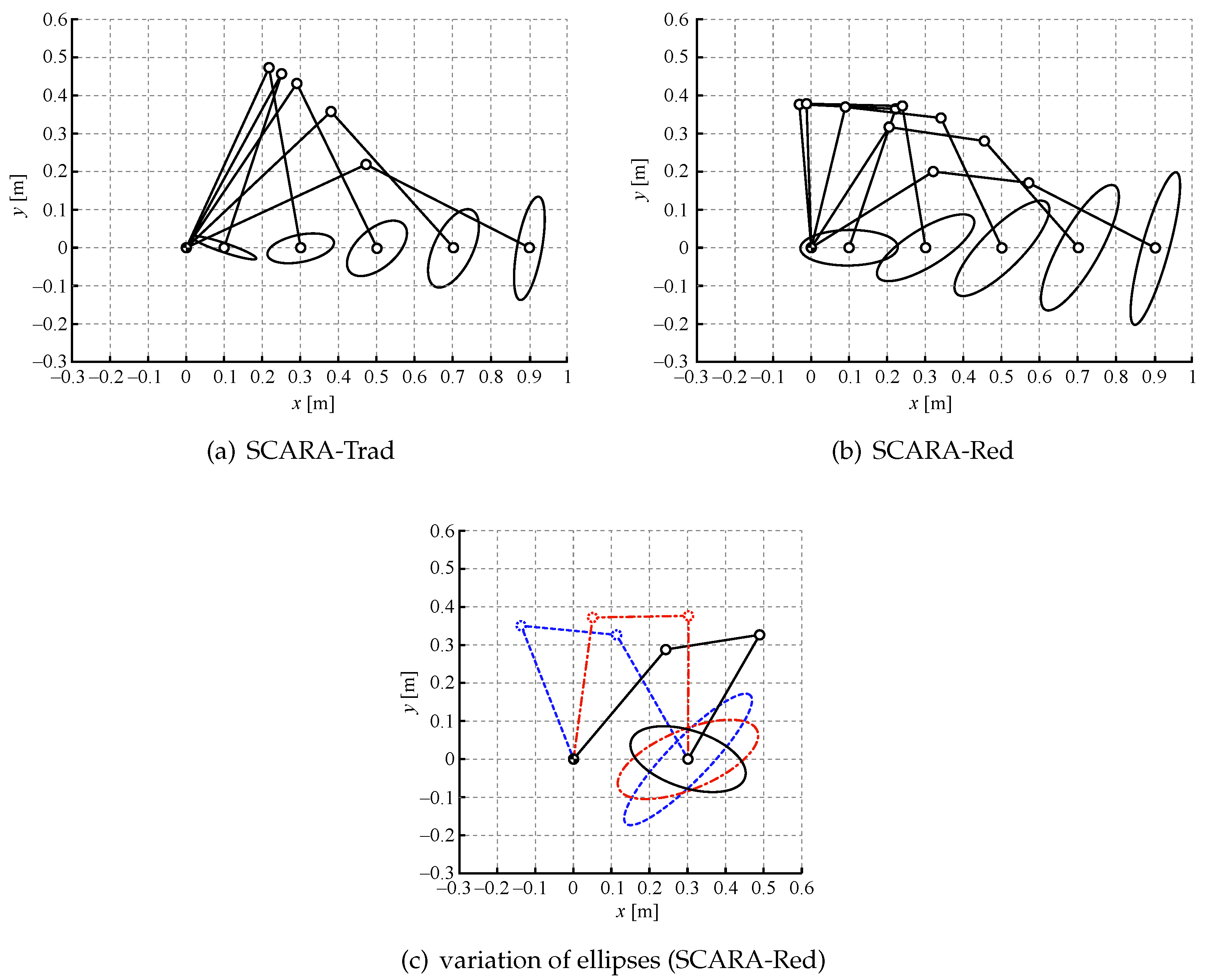
Figure 11.
The different pick-and-place tasks considered in the tests (case b).

Figure 12.
Five different layouts considered in the simulation (case c).

Figure 13.
A typical layout used in simulation to test the performance of pick and place cycles on conveyors with random positions of the object to be manipulated.
Figure 13.
A typical layout used in simulation to test the performance of pick and place cycles on conveyors with random positions of the object to be manipulated.

Figure 14.
Block diagrams of the nonlinear filter to track a trajectory with minimum actuation time [18,19] on the left, and its application to the present task (dashed line just for SCARA-Red) on the right.

Figure 15.
Example of input and output of the nonlinear filter to track a discontinuous set point with a continuous joint motion with bounded velocity and acceleration. From top to bottom: position, velocity and acceleration.
Figure 15.
Example of input and output of the nonlinear filter to track a discontinuous set point with a continuous joint motion with bounded velocity and acceleration. From top to bottom: position, velocity and acceleration.


Table 1.
Technical data of the conventional and the redundant SCARA robot.
| Axis Motor | Gear Ratios | Mass (kg) | Inertia (kgm) | |||||
|---|---|---|---|---|---|---|---|---|
| SCARA-Trad | joint 1 | 9.5 | 19 | 5000 | 30 | 12 | 0.58 | |
| joint 2 | (at 2000 rpm) | (at 2000 rpm) | 20 | 4.8 | 0.21 | |||
| SCARA-Red | joint 1 | 9.5 (at 2000 rpm) | 19 (at 2000 rpm) | 5000 | 30 | 11 | 0.34 | |
| joint 2 | 15 | 6.8 | 0.15 | |||||
| joint 3 | 15 | 4.4 | 0.15 | |||||
| end effector | spin | 1.59 | 3.18 | 6000 | 15 | – | – | – |
| z-axis | (at 3000 rpm) | (at 3000 rpm) | 40 mm/turn | – | – | – | ||
Table 2.
Simulation results of several motion cycles between two fixed positions.
| Cycle # | Length [m] | ||||
|---|---|---|---|---|---|
| 1 T | A1 | B1 | 1.400 | 0.899 | 10% |
| 2 T | A2 | B2 | 1.200 | 0.741 | 26% |
| 3 T | A3 | B3 | 0.800 | 0.848 | 15% |
| 4 R | A4 | B4 | 0.300 | 0.809 | 19% |
| 5 D | A5 | B5 | 0.721 | 0.719 | 28% |
| 6 T | A6 | B6 | 0.600 | 0.639 | 36% |
| 7 R | A7 | B7 | 0.600 | 0.973 | 3% |
| 8 R | A8 | B8 | 0.300 | 0.948 | 5% |
| 9 D | A9 | B9 | 0.361 | 0.858 | 14% |
| 10 D | A10 | B10 | 0.361 | 0.723 | 28% |
| 11 T | A11 | B11 | 0.300 | 0.631 | 37% |
| R = radial direction | maximum | 0.973 | 3% | ||
| D = diagonal direction | minimum | 0.631 | 37% | ||
| T = tangential direction | average | 0.799 | 20% | ||
Table 3.
Results of simulation runs (times in seconds).
| Layout | Optimized Acceleration | Guaranteed Acceleration | ||||||
|---|---|---|---|---|---|---|---|---|
| 1 | ||||||||
| 2 | ||||||||
| 3 | ||||||||
| 4 | ||||||||
| 5 | ||||||||
© 2019 by the authors. Licensee MDPI, Basel, Switzerland. This article is an open access article distributed under the terms and conditions of the Creative Commons Attribution (CC BY) license (http://creativecommons.org/licenses/by/4.0/).
Share and Cite
MDPI and ACS Style
Bussola, R.; Legnani, G.; Callegari, M.; Palmieri, G.; Palpacelli, M.-C. Simulation Assessment of the Performance of a Redundant SCARA. Robotics 2019, 8, 45. https://doi.org/10.3390/robotics8020045
AMA Style
Bussola R, Legnani G, Callegari M, Palmieri G, Palpacelli M-C. Simulation Assessment of the Performance of a Redundant SCARA. Robotics. 2019; 8(2):45. https://doi.org/10.3390/robotics8020045
Chicago/Turabian StyleBussola, Roberto, Giovanni Legnani, Massimo Callegari, Giacomo Palmieri, and Matteo-Claudio Palpacelli. 2019. "Simulation Assessment of the Performance of a Redundant SCARA" Robotics 8, no. 2: 45. https://doi.org/10.3390/robotics8020045
Note that from the first issue of 2016, this journal uses article numbers instead of page numbers. See further details here.