Reconfiguration Analysis of a 3-DOF Parallel Mechanism


1
Department of Mechanical, Chemical and Materials Engineering, University of Cagliari, Piazza d’Armi, 09123 Cagliari, Italy
2
School of Engineering and Physical Sciences, Heriot-Watt University, Edinburgh EH14 4AS, UK
*
Author to whom correspondence should be addressed.
Robotics 2019, 8(3), 66; https://doi.org/10.3390/robotics8030066
Submission received: 25 June 2019
/
Revised: 31 July 2019
/
Accepted: 1 August 2019
/
Published: 2 August 2019
(This article belongs to the Special Issue Kinematics and Robot Design II, KaRD2019)
Abstract
:This paper deals with the reconfiguration analysis of a 3-DOF (degrees-of-freedom) parallel manipulator (PM) which belongs to the cylindrical parallel mechanisms family. The PM is composed of a base and a moving platform shaped as equilateral triangles connected by three serial kinematic chains (legs). Two legs are composed of two universal (U) joints connected by a prismatic (P) joint. The third leg is composed of a revolute (R) joint connected to the base, a prismatic joint and universal joint in sequence. A set of constraint equations of the 1-RPU−2-UPU PM is derived and solved in terms of the Euler parameter quaternion (a.k.a. Euler-Rodrigues quaternion) representing the orientation of the moving platform and of the Cartesian coordinates of the reference point on the moving platform. It is found that the PM may undergo either the 3-DOF PPR or the 3-DOF planar operation mode only when the base and the moving platform are identical. The transition configuration between the operation modes is also identified.
1. Introduction
During the past two decades, a great effort has been made in the research on multi-mode mechanisms (also known as kinematotropic mechanisms, variable-degrees of freedom (DOF) mechanisms, mechanisms with bifurcation or multifurcation and disassembly-free reconfigurable PMs), which are a class of reconfigurable parallel mechanisms (PMs). In multi-mode PMs, fewer actuators are required for the moving platform to perform two or more operation modes and less time is needed in reconfiguring the PM because the process does not need to disassemble the mechanism [1,2,3,4,5,6,7]. The main issue when dealing with a reconfigurable mechanism is its complete kinematic analysis (the reconfiguration analysis) [4,5], consisting of finding all the operation modes (motion patterns) and the transition configurations from one operation mode to an other, which, as it has been noted, represent constraint singular configurations of the PM. There are numerous examples of reconfiguration analyses in the recent literature [8,9,10,11,12,13]. The methods commonly used to solve the analysis are based on algebraic geometry and its numerical implementations [14,15,16,17,18,19]. For example, in References [13,20,21] the Study coordinates are used to represent the motion of the moving platform of a PM and for the kinematic analysis while in References [8,9,22] the position and orientation of the moving platform are represented by using the Cartesian coordinates of a point on the moving platform and the Euler parameter quaternion, respectively. The kinematic interpretation of all the 15 possible cases of the values with a vanished component taken by the Euler parameter quaternion to represent orientation of a rigid body has been presented in Reference [8], firstly. This classification is used in this paper for the reconfiguration analysis of the 3-DOF PM under study.
The paper aims to investigate the operation modes and the transition configurations of the 1-RPU-2-UPU cylindrical parallel mechanism. It is worth noticing that this work will extend the special case of the same PM analyzed by the same authors [23] to the general case. In Reference [23] the mobility analysis was conducted via an analytical procedure based on the screw theory and the kinematic analysis was carried out by taking into account additional constraints to the UPU legs. These constraints forced the UPU legs and the RPU leg to lay on parallel planes in the planar operation mode. In this work the mentioned constrains were released leading to a general case with a wider range of mechanisms with the same function for further optimization. Besides, the method used here proved to be simpler and more convenient than that based on the screw theory providing a more complete analysis of the operation modes of the PM under study. Indeed, the method adopted has allowed to find every possible (even theoretical) operation mode of the PM that the authors did not find in Reference [23] and to clarify which are the operation modes when the platforms’ circumscribed circles have different radii (non-identical case).
The paper is organized as follows: Section 2 briefly recalls the mathematical definition of the Euler parameter quaternion; Section 3 describes the PM architecture under study; Section 4 deals with the reconfiguration analysis of the PM with base and moving platform shaped as identical equilateral triangles; Section 5 revises the reconfiguration analysis by considering the base and moving platform as different equilateral triangles (non-identical case), while Section 6 shows an alternative architecture of the same family of PMs. Finally, the conclusions are drawn.
2. Mathematical Preamble
A rotation about an arbitrary axis can be expressed by four parameters , , in the Euler parameter quaternion [24]:
In Equation (1) is the basis in the Euclidean space . The Euler parameters are isomorphic to the unit quaternion such that:
In general, a vector obtained by a rotation about of a vector can be expressed as:
where is the conjugate of q. A rotation followed by a rotation may be represented by . The product of quaternions follows the multiplication rules:
3. Description of the 1-RPU−2-UPU PM
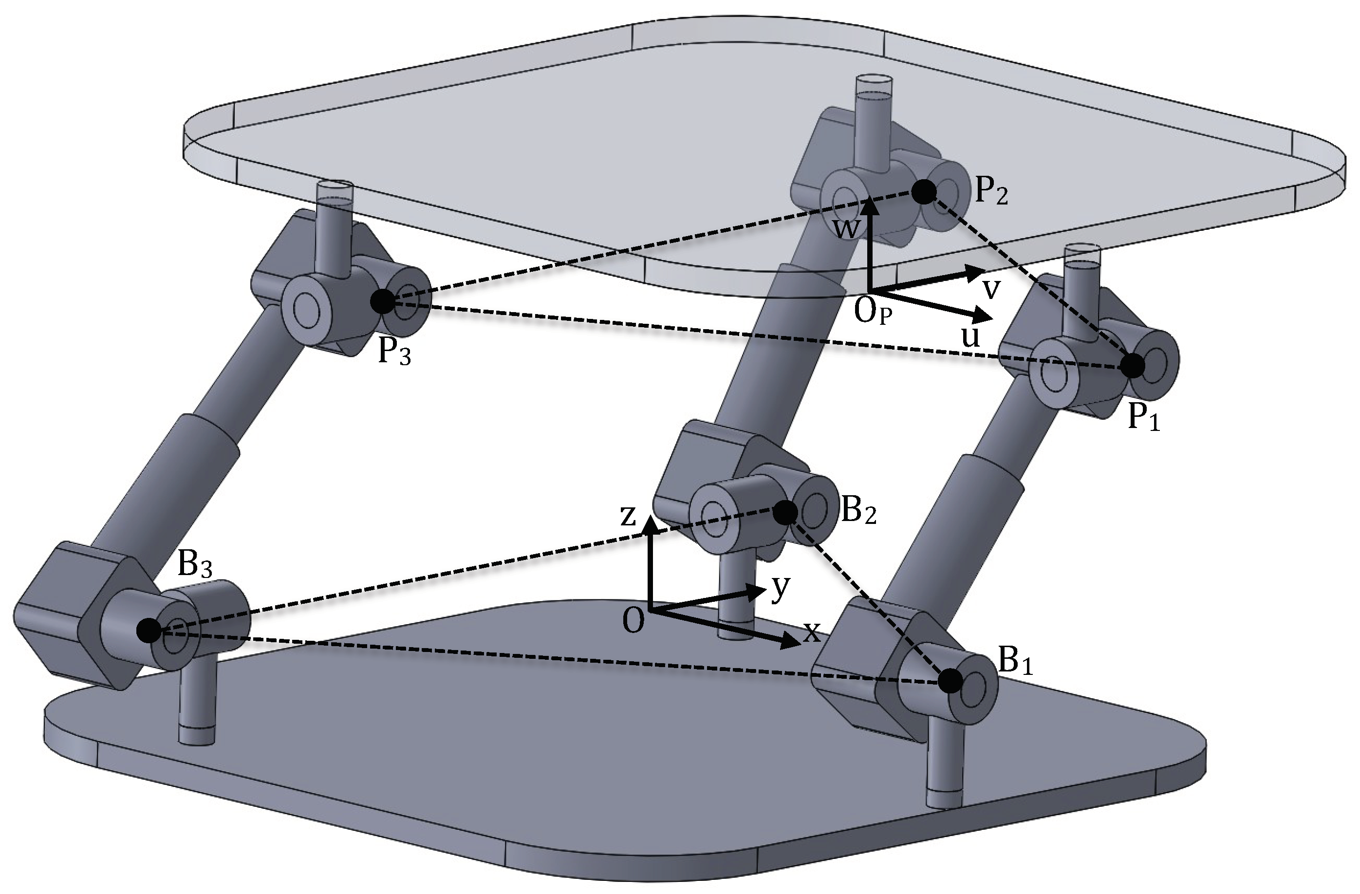
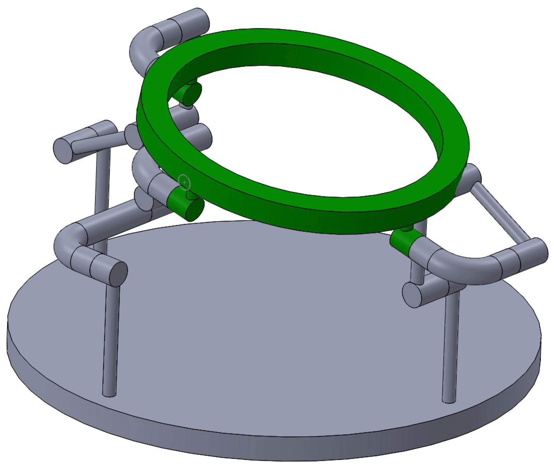
Figure 1 shows the 1-RPU−2-UPU PM under study. The PM is composed by the fixed (base) and the moving platforms connected by three legs. One leg is a serial kinematic chain with R, P and U joints in sequence starting from the base. The other two legs are identical and they are serial kinematic chains with U, P and U joints in sequence starting from the base. The vertical axis of the mounting arrangement intersects the axis of the R joint at at the base. The axes of the U joints intersect at , on the base and , on the moving platform. Points and form two identical equilateral triangles with the radius of their circumscribed circles equal to r. In all legs, the axes of two R joints connected by the P joint are parallel to each other. The direction of each P joint is perpendicular to the axes of its two adjacent R joints.
Let and denote the coordinate frames fixed on the base and on the moving platform, respectively. The x-axis is along the axis of R joint in the RPU leg and normal to the axes of R joints on the base in the U joints of the UPU legs. The u-axis is normal to the axes of R joints on the moving platform in the U joints of all legs. The x- and u-axes pass through the joint’s centers and , respectively. The y- and v-axes are, respectively, located on the plane defined by the axes of the R joints on the base and that defined by the axes of the R joints on the moving platform. The points O and are located at the centroides of the triangles and , respectively. The third axes of the reference systems are normal to the platforms. , , are the the unit vectors along with x-, y-, z-axes while , , are the unit vectors along with u-, v-, w-axes expressed in . The location of in the fixed reference system is given by the position of its center and the orientation denoted by the Euler parameter quaternion q. The unit vectors along the x-axis and along the y-axis can be written in quaternion form as and , respectively, such that:
The positions of are:
The positions of are:
4. Reconfiguration Analysis
The set of the constraints equations of the legs to the moving platform motion are:
- Leg 1: RPU. This leg provides two constraint conditions:
- The R joint-axis at the base is perpendicular to R joint-axis attached to the moving platform:
- The R joint-axis connected to the moving platform belongs to the plane :
- Legs 2 and 3: UPU. Each of these legs provide one constraint condition. The constraint condition is the same for both the legs.
- The R joints-axes attached to the base and the R joints-axes attached to the moving platform are coplanar:where or , depending on which leg is considered.
After simple manipulations, the foregoing constraint equations lead to:
Equation (11) are the kinematic equations sought.
4.1. Operation Modes
Now, we look for all the sets of positive dimension solutions of Equation (11). In other words, we search any possible combination of Euler parameters such to satisfy the Equation (11). The result will give us all the possible operation modes of the PM. Because of the simple form of , i = 1, 2, 3, the sets of positive dimension solutions can be obtained by inspection by searching the values of the Euler parameters able to vanish the left-hand side of Equation (11) and ensuring Equation (2). The results obtained were, then, verified by carrying out the primary decomposition of the ideal associated with the constraint Equation (2).
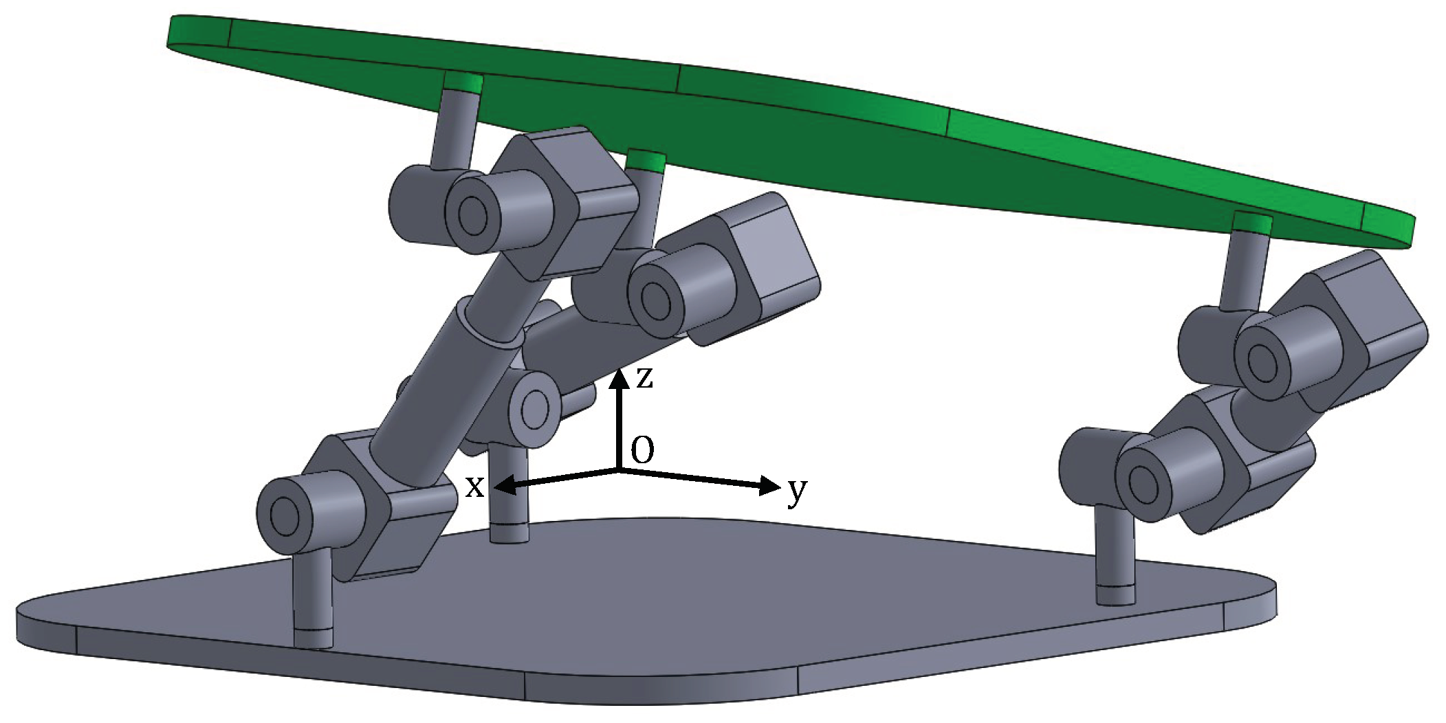
Mode I: 3-DOF PPR operation mode
It represents a rotation by about the y-axis with the position of given by . These two results are in agreement as it can be seen by a simple geometrical proof.
This is a 3-DOF motion of the moving platform. Indeed, there are 3 constraint equations more than Equation (2) that constrain the free motion of the moving platform represented by 7 parameters: . Figure 2 shows the PM undergoing this motion. The transformation matrix is:
with .
The operation mode I is defined PPR in [23].
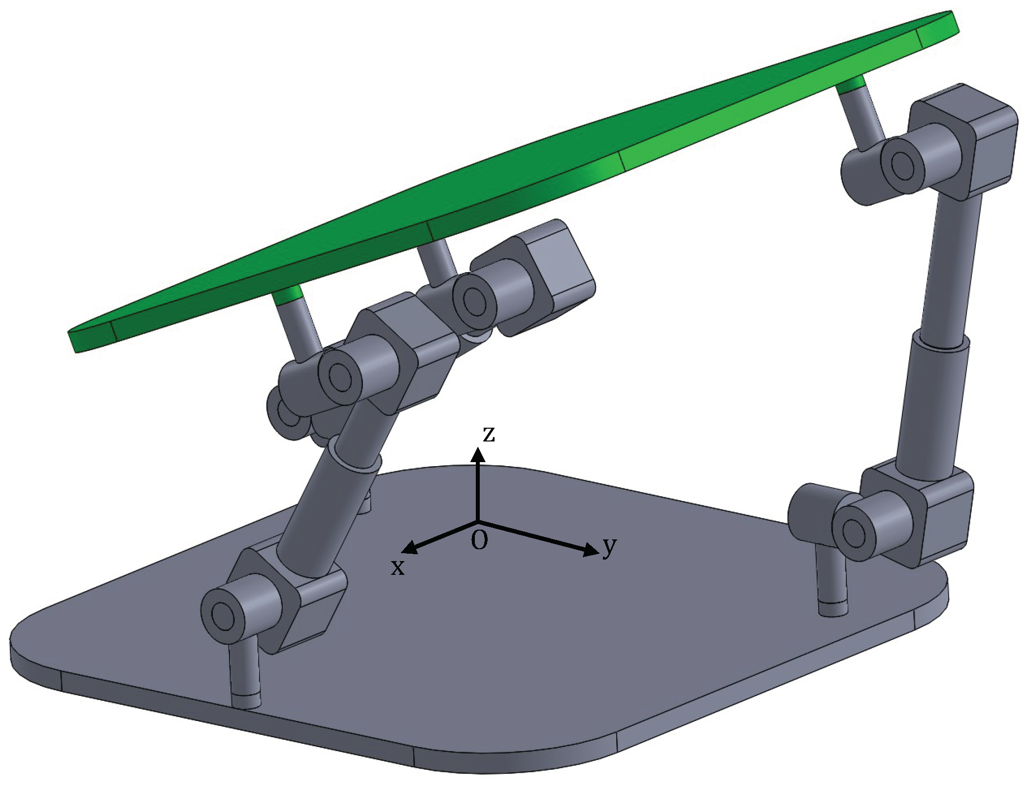
Mode II: 3-DOF planar operation mode
It represents a rotation by about the x-axis. Point can only move on the plane . As for mode I, also this motion is a 3-DOF motion. Figure 3 shows the PM undergoing this motion.
The transformation matrix is:
with . The operation mode II is defined planar motion in [23].
There are other Euler parameters combinations that satisfy Equations (2) and (11). Only one of them leads to an independent motion mode of the PM, namely Mode III, that, on the other side, can be obtained only in theory by disconnecting and reassembling the PM. The other combinations of Euler parameters lead to solutions being subsets of other solutions that cannot be considered independent motion modes of the PM. We call them Solution IV and Solution V. For the sake of completeness, all the results are given in Table 1.
It can be noted that Solution IV is nothing but the limit of mode I whenever the rotation of the moving platform reaches : . Solution V is a composition of mode II (which reaches the half-turn rotation) and mode I. It cannot be obtained without bodies interferences.
4.2. Transition Configurations
Transition configurations are the configurations that allow the PM to switch from one operation mode to an other. In the transition configuration the constraint equations of the associated operation modes have to be guaranteed at the same time.
- Transition configuration between Mode I and Mode II:The constraint equations are:This configuration represents any translation on the plane.Its transformation matrix is: , where denotes the unity matrix and .Figure 1 shows the PM at the transition configuration.
- Other transition configurationsThere can be no transitions between Mode I and Mode III or Mode II and Mode III that can be physically reached. It can be noticed that Solution IV is the transition configuration between Mode I and Mode II when the rotation about -axis is .
5. Reconfiguration Analysis: Non-Identical Case
In this section, the reconfiguration analysis presented in Section 4 is revised when considering the base and the moving platforms as two equilateral triangles with the radius of their circumscribed circles of and , respectively. In this case, Equation (11) become:
Only the positive dimension solutions of Equation (12) that lead to independent motion modes are considered in the following analysis.
The 3-DOF PPR operation mode (Mode I) is still possible in this case. Indeed, the moving platform can rotate about the y-axis and . The 3-DOF planar operation mode (Mode II) is no longer possible in this case. Indeed, it is trivial to show that Equation (12) may be guaranteed if and only if . Mode III is not affected by the dimensions of the base and moving platform and it is only possible in theory.
Transition configurations are not considered in this case as the PM may undergo an unique operational mode (PPR) with physics and geometry always guaranteed.
6. Other PMs Architectures
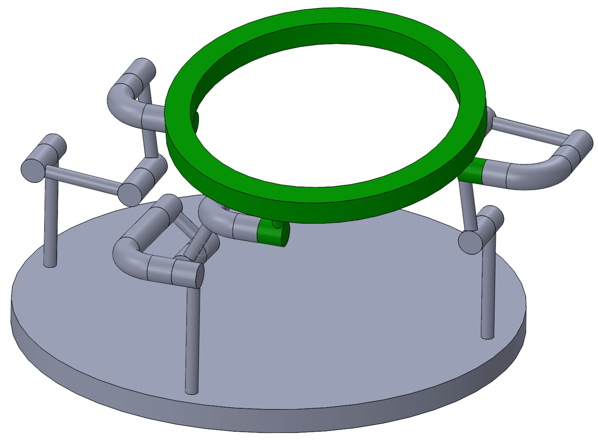
In general, any PM with the same set of constraint equations of that used for the 1-RPU−2-UPU leads to the operation modes analyzed [25]. For example, in Figure 4 and Figure 5 the 1-URU-2-RRU PM is shown in the 3-DOF PPR and in the 3-DOF planar operation mode, respectively. As can be seen there are two legs with two constraint equations, one leg with one. Further, the intermediate P joint is substituted by an R joint to form a leg with 3−R planar kinematic chain.
7. Conclusions
The paper has presented a systematic reconfiguration analysis of a 1-RPU−2-UPU and other PMs with the same set of constraint equations as the 1-URU−2-RRU PM. The use of the Euler parameter quaternion and of the Cartesian coordinates of a point on the moving platform has proved to be convenient and simple for the analysis of this type of PMs. Indeed, the analysis leads to the operation modes of the PM in a straightforward manner with no need of any algebraic geometry method that was used only to verify the results obtained. In the case of two identical equilateral triangles as base and moving platform of the PM, the analysis shows two possible operation modes: the 3-DOF PPR and the 3-DOF planar modes. The former is a rotation about the y-axis whilst the latter is a rotation about the x-axis and a translation on the plane of the reference point on the moving platform. An other theoretical operation mode was found since it requires to disconnect and reassemble the PM. As expected, the transition between the two operation modes occurs when the platform has no rotation and the reference point of the moving platform lies onto plane.
When the base and the moving platform are equilateral triangles of different sizes, the only operation mode is the 3-DOF PPR. Therefore, in this case, the PM no longer has multiple operation modes.
Future work will focus on the optimization of this multi-mode PM and developing a prototype able to switch between the different modes by eliminating the constraint singularity. The main idea is to use lockable (planar parallelogram) and R joints as proposed in Reference [26].
Author Contributions
Conceptualization, X.K. and M.R.; formal analysis, M.R. and X.K.; writing—original draft preparation, M.R.; writing—review and editing, X.K.
Funding
This research received no external funding.
Conflicts of Interest
The authors declare no conflict of interest.
References
- Ding, X.; Kong, X.; Dai, J.S. Advances in Reconfigurable Mechanisms and Robots II; Springer International Publishing: Cham, Switzerland, 2016. [Google Scholar]
- Kong, X.; Gosselin, C.; Richard, P.L. Type synthesis of parallel mechanisms with multiple operation modes. J. Mech. Des. 2007, 129, 595–601. [Google Scholar] [CrossRef]
- Kong, X. Type synthesis of 3-DOF parallel manipulators with both a planar operation mode and a spatial translational operation mode. J. Mech. Robot. 2013, 5, 041015-1–041015-8. [Google Scholar] [CrossRef]
- Fanghella, P.; Galletti, C.; Gianotti, E. Parallel robots that change their group of motion. In Advances in Robot Kinematics; Lenarcic, J., Roth, B., Eds.; Springer: Dordrecht, The Netherlands, 2006; pp. 49–56. [Google Scholar]
- Refaat, S.; Hervé, J.M.; Nahavandi, S.; Trinh, H. Two-mode overconstrained three-DOFs rotational-translational linear-motor-based parallel kinematics mechanism for machine tool applications. Robotica 2007, 25, 461–466. [Google Scholar] [CrossRef]
- Li, Q.; Hervé, J.M. Parallel mechanisms with bifurcation of Schoenflies motion. IEEE Trans. Robot. 2009, 25, 158–164. [Google Scholar]
- Gogu, G. Maximally regular T2R1-type parallel manipulators with bifurcated spatial motion. J. Mech. Robot. 2011, 3, 011010-1–011010-8. [Google Scholar] [CrossRef]
- Kong, X. Reconfiguration analysis of a 3-DOF parallel mechanism using Euler parameter quaternions and algebraic geometry method. Mech. Mach. Theory 2014, 74, 188–201. [Google Scholar] [CrossRef]
- Kong, X. Reconfiguration analysis of a 4-DOF 3-RER parallel manipulator with equilateral triangular base and moving platform. Mech. Mach. Theory 2016, 98, 180–189. [Google Scholar] [CrossRef]
- Kong, X. Reconfiguration Analysis of Multimode Single-Loop Spatial Mechanisms Using Dual Quaternions. ASME J. Mech. Robot. 2017, 9, 051002-1–051002-8. [Google Scholar] [CrossRef]
- Carbonari, L.; Callegari, M.; Palmieri, G.; Palpacelli, M.C. A new class of reconfigurable parallel kinematic machines. Mech. Mach. Theory 2014, 79, 173–183. [Google Scholar] [CrossRef]
- Carbonari, L.; Callegari, M.; Palmieri, G.; Palpacelli, M.C. Analysis of kinematics and reconfigurability of a spherical parallel manipulator. IEEE Trans.Robot. 2014, 30, 1541–1547. [Google Scholar] [CrossRef]
- Nurahmi, L.; Schadlbauer, J.; Caro, S.; Husty, M.; Wenger, P. Kinematic analysis of the 3-RPS cube parallel manipulator. J. Mech. Robot. 2015, 7, 011008-1–011008-11. [Google Scholar] [CrossRef]
- Cox, D.A.; Little, J.B.; O’Shea, D. Ideals, Varieties, and Algorithms; Springer: New York, NY, USA, 2007. [Google Scholar]
- Sommese, A.J.; Wampler, C.W. The Numerical Solution of Systems of Polynomials Arising in Engineering and Science; World Scientific Press: Singapore, 2005. [Google Scholar]
- Decker, W.; Pfister, G. A First Course in Computational Algebraic Geometry; Cambridge University Press: New York, NY, USA, 2013. [Google Scholar]
- Kong, X. A variable-DOF single-loop 7R spatial mechanism with five motion modes. Mech. Mach. Theory 2018, 120, 239–249. [Google Scholar] [CrossRef]
- Walter, D.R.; Husty, M.L. Kinematic analysis of the TSAI 3-UPU parallel manipulator using algebraic methods. In Proceedings of the 13th IFToMM World Congress in Mechanism and Machine Science, Guanajuato, Mexico, 19–25 June 2011; pp. 1–10. [Google Scholar]
- Schadlbauer, J.; Walter, D.R.; Husty, M. The 3-RPS parallel manipulator from an algebraic viewpoint. Mech. Mach. Theory 2014, 75, 161–176. [Google Scholar] [CrossRef]
- Walter, D.R.; Husty, M.L.; Pfurner, M. Chapter A: Complete Kinematic Analysis of the SNU3-UPU Parallel Manipulator, Contemporary Mathematics; American Mathematical Society: Providence, RI, USA, 2009; Volume 496, pp. 331–346. [Google Scholar]
- Nurahmi, L.; Caro, S.; Wenger, P.; Schadlbauer, J.; Husty, M. Reconfiguration analysis of a 4-RUU parallel manipulator. Mech. Mach. Theory 2016, 96, 269–289. [Google Scholar] [CrossRef] [Green Version]
- Kong, X. Reconfiguration Analysis of a Variable Degrees-of-Freedom Parallel Manipulator With Both 3-DOF Planar and 4-DOF 3T1R Operation Modes. In Proceedings of the ASME 40th Mechanisms and Robotics Conference, Charlotte, NC, USA, 21–24 August 2016. [Google Scholar]
- Ruggiu, M.; Kong, X. Mobility and kinematic analysis of a parallel mechanism with both PPR and planar operation modes. Mech. Mach. Theory 2012, 55, 77–90. [Google Scholar] [CrossRef]
- Spring, K.W. Euler parameters and the use of quaternion algebra in the manipulation of finite rotations: A review. Mech. Mach. Theory 1986, 21, 365–373. [Google Scholar] [CrossRef]
- Kong, X.; Gosselin, C.M. Type Synthesis of Parallel Mechanisms; Springer: Berlin, Germany, 2007. [Google Scholar]
- Chablat, D.; Kong, X.; Zhang, C. Kinematics, Workspace, and Singularity Analysis of a Parallel Robot with Five Operation Modes. J. Mech. Robot. 2018, 10, 035001-1–035001-12. [Google Scholar] [CrossRef]
Figure 1.
The 1-RPU−2-UPU PM geometry.

Figure 2.
The 1-RPU−2-UPU PM undergoing the 3-DOF PPR operation mode (Mode I).

Figure 3.
The 1-RPU−2-UPU PM undergoing the 3-DOF planar operation mode (Mode II).

Figure 4.
The 1-URU−2-RRU PM undergoing the 3-DOF PPR operation mode.

Figure 5.
The 1-URU−2-RRU PM undergoing the 3-DOF planar operation mode.


Table 1.
Other solutions from the kinematic equations.
| Mode III: | : | . | Half-turn rotation about the z-axis. |
| Solution IV: | : | . | Half-turn rotation about the y-axis. |
| Solution V: | : | . | Half-turn rotation about the x-axis followed by a rotation by about the y-axis. |
© 2019 by the authors. Licensee MDPI, Basel, Switzerland. This article is an open access article distributed under the terms and conditions of the Creative Commons Attribution (CC BY) license (http://creativecommons.org/licenses/by/4.0/).
Share and Cite
MDPI and ACS Style
Ruggiu, M.; Kong, X. Reconfiguration Analysis of a 3-DOF Parallel Mechanism. Robotics 2019, 8, 66. https://doi.org/10.3390/robotics8030066
AMA Style
Ruggiu M, Kong X. Reconfiguration Analysis of a 3-DOF Parallel Mechanism. Robotics. 2019; 8(3):66. https://doi.org/10.3390/robotics8030066
Chicago/Turabian StyleRuggiu, Maurizio, and Xianwen Kong. 2019. "Reconfiguration Analysis of a 3-DOF Parallel Mechanism" Robotics 8, no. 3: 66. https://doi.org/10.3390/robotics8030066
Note that from the first issue of 2016, this journal uses article numbers instead of page numbers. See further details here.