Characterization and Lubrication of Tube-Guided Shape-Memory Alloy Actuators for Smart Textiles


1
Department of Engineering Mathematics, University of Bristol, Bristol BS8 1UB, UK
2
SoftLab, Bristol Robotics Laboratory, Bristol BS16 1QY, UK
3
Cardiff School of Engineering, Cardiff University, Cardiff CF24 3AA, UK
*
Author to whom correspondence should be addressed.
Robotics 2019, 8(4), 94; https://doi.org/10.3390/robotics8040094
Submission received: 25 September 2019
/
Revised: 22 October 2019
/
Accepted: 4 November 2019
/
Published: 8 November 2019
(This article belongs to the Special Issue Soft Machines: Integrating Sensing, Actuation and Computation)
Abstract
:Smart textiles are flexible materials with interactive capabilities such as sensing, actuation, and computing, and in recent years have garnered considerable interest. Shape-memory alloy (SMA) wire is well-suited for smart textiles due to its high strength, small size, and low mass. However, the contraction of SMA wire is low, limiting its usefulness. One solution to increasing net contraction is to use a long SMA wire and guide it inside a tube that is wound back and forth or coiled inside a smart textile. In this article, we characterize the performance of tube-guided SMA wire actuators. We investigate the effect of turn radius and number of loops, showing that the stroke of an SMA-based system can be improved by up to 69.81% using the tube-guided SMA wire actuator concept. Finally, we investigate how tube-guided SMA wire actuators can be lubricated to improve their performance. Coarse graphite powder and tungsten disulfide lubricant both delivered improvements in stroke compared with an unlubricated system.
1. Introduction
Smart textiles are textile-based devices capable of any combination of sensing, actuation, communication, power storage, and power generation, and have garnered considerable interest in recent years [1]. Shape-memory alloy (SMA) wire is often used to deliver actuation in smart textiles [2,3,4,5] since it exhibits high stress up to 200 MPa, work density around 1000 kJ m−3, and specific power around 1000 W kg−1 [6]. These performance metrics allow smart textiles powered by SMA wire to exert high forces and deliver high energies and powers whilst still being small and light.
One drawback, however, of SMA wire actuators is their limited contraction, which is typically around 5% [6]. One solution to overcome this is to ‘train’ the SMA wire such that its memory shape is a linear coil [7]. These SMA coils or springs exhibit high contractions (as high as 70% of their extended length [8]) at the cost of considerably reduced maximum stress and efficiency, and increased cooling requirements [9]. However, the reduced stress of SMA coils, in addition to their non-fibrous form factor, makes them less suitable for smart textile applications compared with uncoiled SMA wire.
The limited contraction of SMA wire presents a problem for smart textiles, since many applications require large strokes. Assistive orthotics for example, a common application for smart textiles, often require actuators to deliver strokes exceeding several centimeters to assist limb movement. If the smart textile is to be actuated using SMA wire, this would imply the textile’s length should be in the order of meters to deliver the requisite stroke. This is typically impractical.
A proposed solution to this challenge is to use a long SMA wire, and wind it back and forth inside or circumferentially around the orthotic in question, such that while the SMA length is large, the device length remains small. SMAs wound on the surface of drums, for example, have been predicted to deliver strokes as high as 50% of drum radius, provided that friction is kept low [10]. In practice, these low frictions have been achieved using rolling-contact architectures such as ball-bearings, allowing for experimental strokes of 20% of drum radius [10]. However, this solution is somewhat complicated, requiring a large number of bearings in a small volume to support the SMA wire. Furthermore, the non-planar morphology of wire-on-drum SMA actuators makes them poorly suited for smart textile applications.
An alternative solution involves threading the SMA wire through a guiding tube, which can then be wound back and forth inside or around the target orthotic. When the SMA wire is heated, it contracts within the tube, which prevents radial or tangential movement of the SMA and ensures only axial contraction occurs. Assuming the guiding tube and one end of the SMA wire is anchored in place, the other end of the SMA wire can be attached to a load to do useful work. The broader tube-guided cable concept, whereby a tendon or cable is routed through a guiding tube, has been used successfully for decades in many applications, the most well-known being bicycle brake cables. In terms of smart textiles, tube-guided cables (often called Bowden cables) have been used in orthotics for post-stroke shoulder rehabilitation [11] and exosuits for walking assistance at the ankle [12,13,14,15] and/or the hip [16,17]. In some cases, the actuator is transported behind the exosuit on a trolley, with a tube-guided cable delivering forces to the suit remotely [18]. Tube-guided cables have also been used in robotic gloves to restore grasping ability in subjects with paralyzed hands [19] and in arm orthotics for upper limb rehabilitation [20].
The tube-guided SMA wire actuator concept has been applied to an anthropomorphic robotic hand [21] and to soft wearable robots [22], as well as investigated as a concept for integration of actuators into confined spaces [23]. In those studies, there has been some exploration of the trade-offs associated with the use of tube-guided SMA wire actuators. For example, one study investigated looping the SMA wire around a pulley and then back along the same guiding tube. This was found to impair the SMA wire stroke, which was attributed to increased friction [22]. Another study varied the angle by which a tube-guided SMA wire actuator was wound around a 200 mm diameter cylinder, demonstrating that when the SMA wire was wound around the entire cylinder (winding angle 360°), the stroke was impaired by up to 35%, similarly attributed to friction [23]. However, both studies focused on the concept and design of tube-guided SMA wire actuators rather than characterizing them in depth.
In this article, we describe a broad, detailed characterization of tube-guided SMA wire actuators. We focus especially on wound actuators, whereby parts of the guiding tube follow circular turns. Wound tube-guided SMA wire actuators are especially suitable for smart textiles (where they can take the place of the warp or weft of the material) and have key applications for orthotics. We investigate how the diameter of the circular turn of wound actuators, and the total number of loops of coiled actuators, effect contraction. Finally, we describe experiments performed to investigate lubrication of the SMA within the tube, with the aim of minimizing SMA-tube friction and ultimately maximizing actuation.
2. Materials and Methods
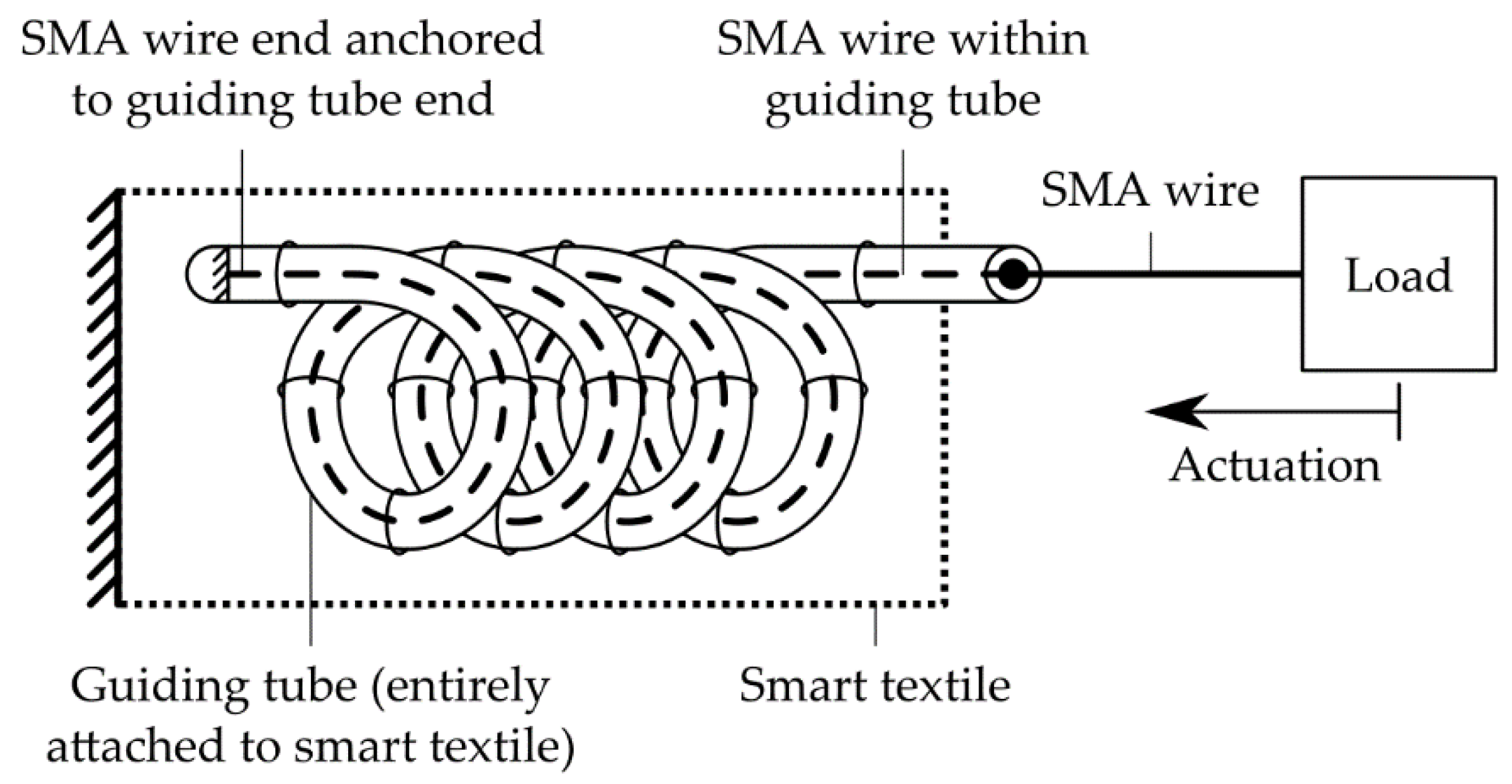
The tube-guided SMA wire actuator concept is shown in Figure 1. An anchored guiding tube allows the SMA wire to be wound back and forth or round and round within a small volume, allowing a small device to contain a long length of SMA wire, such that a large stroke can be delivered. Figure 1 shows a tube-guided SMA wire actuator embodied within a smart textile, with both the guiding tube and one end of the SMA anchored to the smart textile, and the free end of the SMA attached to a load where it may deliver actuation. It is essential that the guiding tube is well anchored to the smart textile for the efficacy of the device; if the guiding tube is free to move it may be deformed considerably by the contraction of the SMA wire and the stroke delivered to the load may be reduced. Actuation is triggered by ohmic heating of the SMA wire, achieved by applying a voltage across its length.
For the experiments described in this article, we used nickel titanium shape-memory alloy wire with a diameter of 150 μm (BMF150, Toki Corporation, Tokyo, Japan). The phase-transition temperature of the wire was 70 °C; detailed information is available from the product datasheet. The SMA wire was always measured in a fully austenitic state for the purposes of determining reference length. Prior to experimental data collection, the SMA wire samples were tested extensively in initial experiments, therefore the training effect associated with SMA wire did not influence the results presented here.
For the guiding tube, we used polytetrafluoroethylene (PTFE) tubing with an internal diameter of 1.3208 mm and external diameter of 1.9304 mm (WZ-06417-51, Cole-Parmer, Vernon Hills, IL, USA). Practically, rather than embodying the tube-guided SMA wire actuator in a smart textile, we mounted the devices on a test rig to maintain the tube-guided SMA in various test configurations, so that we could investigate variables such as turn diameter and number of loops in a controlled environment.
It should be noted that the internal diameter of the PTFE tubing is considerably larger than the external diameter of the SMA wire used in the experiments presented here. In practical tube-guided SMA wire applications, the external diameter of the SMA wire should closely match the internal diameter of the guiding tube, so that the SMA wire remains centered and in even contact with the guiding tube. If a larger diameter guiding tube is used, the SMA wire may be free to move within the guiding tube, which can impair stroke and introduce nonlinear behavior. To avoid this in experiments described in this article, the tube-guided SMA wire was always wound or coiled in the same direction, which ensured that the SMA wire rested against and remained in contact with the internal wall of the guiding tube, matching the case where the two diameters are well matched.
To characterize the contraction of tube-guided SMA wire actuators, we designed and built a test rig. The test rig consisted of a rigid frame and linearly moving carriage (Figure 2). The test sample was attached to the rigid frame, such that contraction of the SMA wire inside the guiding tube induced movement of the carriage. We wished to measure the maximum contraction that the sample was capable of, and thus did not use a constant mass to exert a known force at the end of the SMA wire, which would have reduced contraction. The only forces resisting the motion of the carriage were frictional forces associated with the carriage. The carriage was supported by four low-friction, self-lubricating sliding elements which moved along linear rails (Drylin N, Igus, Cologen, Germany), to keep these frictional forces to a minimum. A laser displacement sensor (LK-G152, Keyence, Osaka, Japan) was used to measure displacement, which was pointed towards an opaque surface on the carriage. Data was collected using a computer running MATLAB, which interfaced with the laser displacement sensor using a data acquisition device (NI USB-6009, National Instruments, Austin, TX, USA).
Four experiments were undertaken to investigate the behavior of tube-guided SMA wire actuators:
- Straight contraction: Recording the contraction of a straight sample of SMA wire to determine a baseline contraction for comparison with other experiments.
- Turn radius: Investigating the effect of turn radius upon the contraction of a tube-guided SMA wire actuator with a single 180° turn.
- Number of loops: Investigating the effect of the number of loops in a coiled tube-guided SMA wire actuator upon contraction.
- Lubricant: Investigating the effect of lubricant upon the contraction of a coiled tube-guided SMA wire actuator.
2.1. Straight Contraction
In the straight contraction experiment, as a control measurement, the contraction of a 290 mm long sample of SMA wire, moving freely rather than within a guiding tube, was recorded. The manufacturer’s suggested drive voltage per length of the SMA used was 20.7 V m−1, implying a drive voltage of 6.003 V. In later experiments, the drive voltage applied was set depending on the SMA wire length, such that 20.7 V m−1 was always applied. Data was recorded with a drive voltage of zero for three seconds, and then the desired drive voltage was applied for seven seconds, while data continued to be recorded. After each experiment, the SMA was allowed to return to room temperature and its fully relaxed state before the next experiment.
2.2. Turn Radius
Next, we investigated the effect of turn radius upon the contraction of a tube-guided SMA wire actuator with a single 180° turn. It was expected that smaller turn radii would increase friction between the guiding tube and the SMA, reducing stroke. Two acrylic plates were laser cut and laser etched to form curved tracks within which the tube-guided SMA wire actuator could be mounted (Figure 3). The turn radii tested ranged from 10 to 110 mm.
The length of each acrylic plate was 290 mm, matching the length of the SMA wire in the straight contraction experiment, however the turn radius experiment featured a long tube-guided SMA wire actuator with a single turn. This allowed a longer length of SMA wire to be used compared with the straight contraction experiment and highlights how the tube-guided SMA wire actuator concept allows a longer length of SMA wire to be used within a shorter length system. The length of the SMA wire within the tube-guided SMA wire actuator was 650 mm.
In this and subsequent experiments, the SMA wire’s contraction was limited compared with the straight contraction experiment due to frictional interactions with the guiding tube. As such, more time was required for the tube-guided SMA wire to reach full contraction, and the experiment duration was extended from ten seconds to one minute. Data was recorded with a drive voltage of zero for three seconds, and then the desired drive voltage was applied for 57 s, while data continued to be recorded. As before, after each experiment, the SMA was allowed to return to room temperature and its fully relaxed state before the next experiment.
2.3. Number of Loops
We investigated differences in contraction due to the number of loops present in a coiled tube-guided SMA wire actuator. It was expected that increasing the number of loops would negatively impact contraction, as predicted by the capstan equation [23], which describes how friction influences the holding force of a loaded, flexible line lying along the surface of a cylinder. A 1000 mm long tube-guided SMA wire actuator was wrapped between zero and four times around a 50 mm diameter acrylic tube, adhered by hot-melt glue (Figure 4). The acrylic tube was fixed in place using a tightened bolt and was not able to rotate. At one end of the tube-guided SMA wire actuator (where the SMA was free to move), the SMA was attached to the linearly moving carriage, while the other end of the tube-guided SMA wire actuator was held in place by a vice, in-line with the measured end. As in other experiments, the displacement of the linearly moving carriage was recorded when the SMA was activated by ohmic heating.
2.4. Lubricant
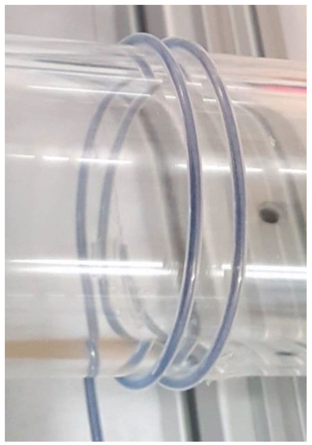
Finally, we considered the application of lubricants to the tube-guided SMA wire actuator, with the aim of reducing friction between the SMA wire and guiding tube in order to improve stroke. The lubricants tested in this experiment are shown in Table 1. In all experiments, a coiled tube-guided SMA wire actuator with two loops was used, wound around a 50 mm diameter cylinder, matching the two-loops trials in the number of loops experiment (Figure 5).
To prepare the soap–water mixture, a precursor material for making soap bars (Melt and Pour Crystal Soap Base, Stephenson Personal Care, Bradford, UK) was mixed with water at a mass ratio of either 1:1 or 1:3. The resultant mixture was injected into the guiding tube by syringe. Two samples of graphite powder were evaluated, a fine powder (Kasp Security K30050, Carl Kammerling, Wuppertal, Germany) and a coarse powder (1033-6090, Fisher Scientific, Pittsburgh, PA, USA). The graphite powders were added to the guiding tube dry, using a pipette. As an alternative lubrication method, both powders were suspended in isopropyl alcohol (IPA). The suspended powders were then added to the guiding tube by pipette. Subsequently, the IPA evaporated, leaving behind a graphite powder coating. A PTFE lubricant spray (Dry PTFE Lubricant, WD-40 Company, San Diego, CA, USA) was also evaluated, and finally a tungsten–disulfide-based lubricant (AR2500 Nano WS2 Lubricant, Archoil, Wallingford, CT, USA). Both the PTFE lubricant and tungsten–disulfide-based lubricant were first measured into plastic weigh boats before being added to the guiding tube by pipette.
3. Results
3.1. Straight Contraction
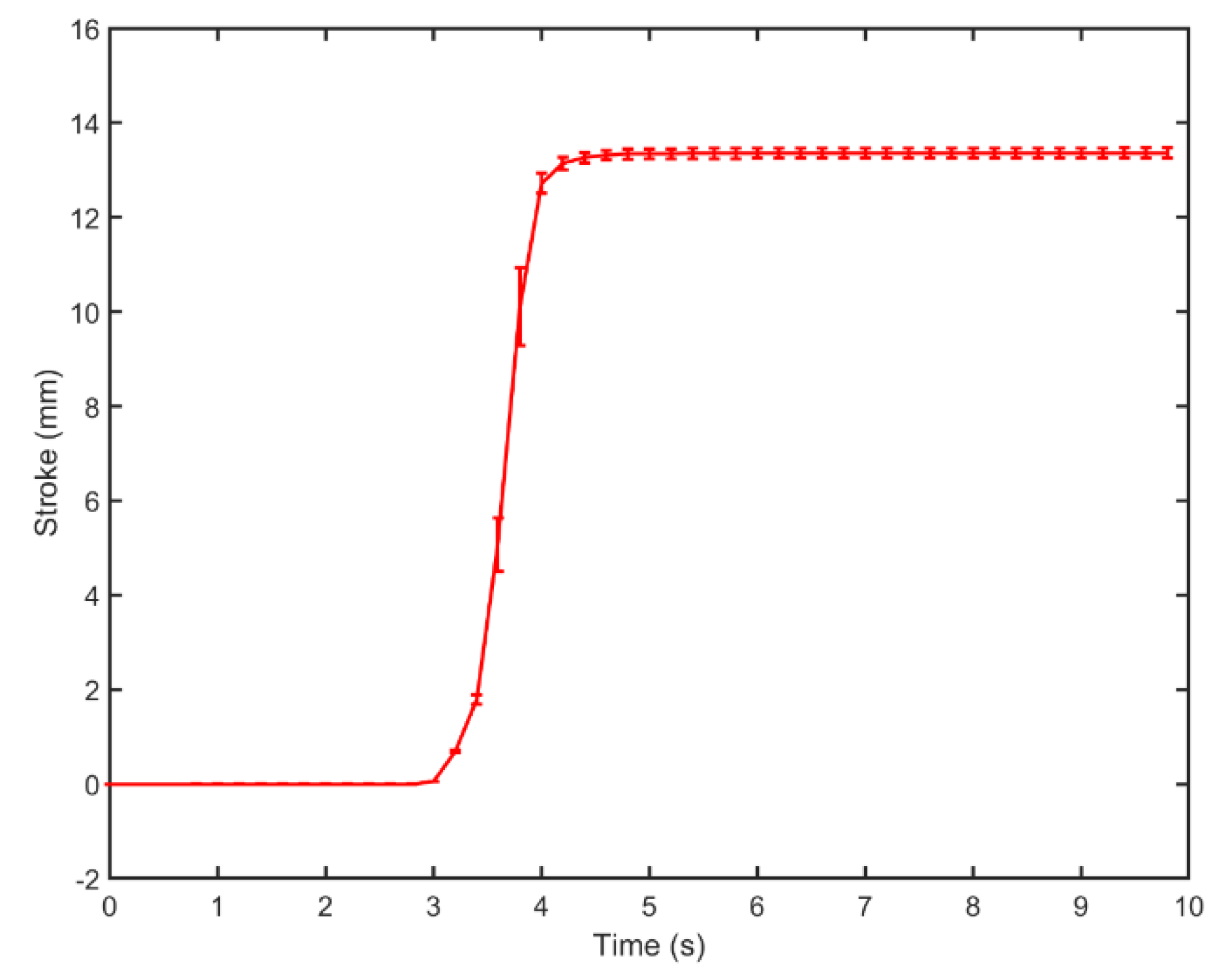
Figure 6 shows the contraction of the straight actuator with no tube. At the three-second mark, 20.7 V m−1 was applied to the SMA wire. The SMA wire shortened quickly over several seconds and after seven seconds of ohmic heating the average stroke was 13.35 mm. Given the total SMA wire length of 290 mm, this corresponds to a contraction of 4.6%, close to the expected 5% of NiTi SMA wire.
3.2. Turn Radius
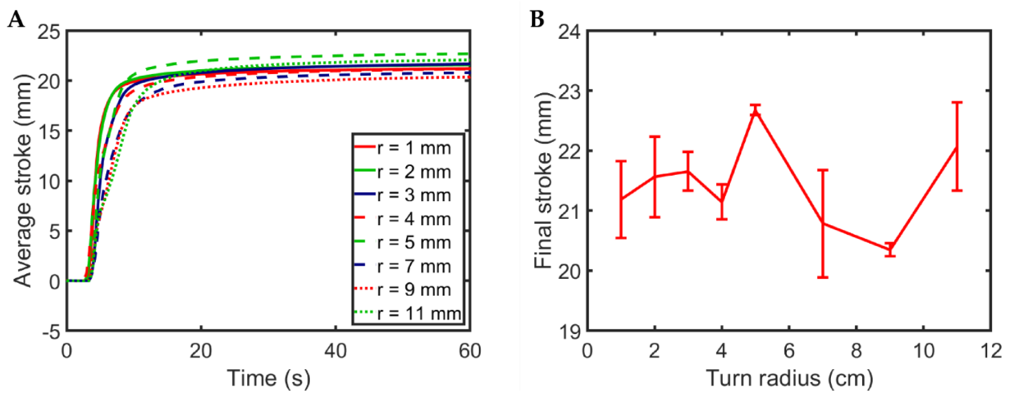
Figure 7 shows the effect of turn radius on stroke. In contrast to our expectations, stroke appeared to be independent of turn radius. One explanation for this is the inverse relationship between loaded area and loading pressure as turn radius is altered; small turn radii imply the frictional force between the SMA and guiding tube is applied over a smaller area, thus the frictional pressure is greater. The loaded area is proportional to the turn radius . The loading pressure is proportional to the net normal force exerted by the SMA on the guiding tube divided by the loaded area. This interaction is consistent with the Coulomb model of friction:
where is frictional force and is the coefficient of friction. As in the Coulomb model of friction, the friction experienced by an SMA contracting with a fixed axial force within a guiding tube appears to be independent of contact area.
While the length of the SMA wire in this experiment was 650 mm, the length of the acrylic plate was 290 mm, matching the total SMA wire length from the straight contraction experiment (Section 3.1). The highest final average stroke using the acrylic plate was 22.67 mm, far exceeding the 13.35 mm achieved with SMA wire of the same length. This demonstrates how tube-guided SMA wire actuator systems can deliver higher strokes compared with solely SMA wire systems, overcoming the low contraction of SMA wire itself. In tube-guided SMA wire actuators, a longer length of SMA wire is contained within a small system, allowing a larger stroke than could be achieved by using a single piece of SMA wire. In this case, the SMA wire within the tube-guided SMA wire actuator is 2.24 times longer than the SMA wire used in the straight contraction experiment. We note that the contraction of the 650 mm long SMA wire was 3.48% (22.67/650), lower than the 4.6% (13.35/290) achieved by the single piece of SMA wire. While the presence of the tube in the tube-guided SMA wire actuator does impair the contraction of the SMA, it also allows a much longer length of SMA wire to be contained within a small space, allowing overall stroke to be improved (22.67 vs. 13.35 for the same ‘system length’, i.e., the length occupied by the system for the purposes of its inclusion in a device).
3.3. Number of Loops
The relationship between the number of tube loops and total stroke is shown in Figure 8. As expected, increasing the number of loops resulted in reduced stroke, as a consequence of increased frictional loading. Adding a single loop to a tube-guided SMA wire actuator was found to reduce average final stroke from 38.75 to 20.07, roughly a 48% reduction. This finding is consistent with previous analysis of tube-guided SMA wire actuators, which observed a 35% reduction in stroke when the winding angle was increased to 360° (corresponding to one loop) [23]. Increasing the number of loops to two further reduced average final stroke to 8.42 mm, a 78% reduction compared with the zero loops case.
Surprisingly, increasing the number of loops beyond two did not further reduce average final stroke, diverging from the predictions of the capstan equation [23]. For systems that follow the capstan equation, increasing the number of loops eventually results in line being completely immobile, whereas here the tube-guided SMA wire actuator was able to deliver some stroke no matter the number of loops.
One explanation for this behavior is the ability of SMA wire to contract all along its length, in contrast to the capstan equation, which models a non-contracting flexible line wound around a cylinder with tensile loads applied at each end. In the case of this experiment, for the SMA wire there always exists some section that is unimpeded by frictional loading. For example, the section of SMA wire between the linearly moving carriage and the coiled section of the tube-guided SMA wire actuator will always be free to move and thus will always contribute a small amount of contraction. The next section of SMA wire, within the first loop, only experiences the frictional effects of a single loop, and so will also contribute some contraction. The next section of SMA wire experiences the frictional contribution of two loops, and so on, with the final section of SMA wire experiencing the frictional effects of the full number of loops present. Thus, no matter the number of loops, there are always some sections of SMA wire that are unimpeded or less impeded by frictional loading and thus are able to contribute to overall contraction.
It is also possible that the coefficient of friction between SMA wire and PTFE tube is not constant. For example, it may vary as a function of load or temperature.
3.4. Lubricants
Figure 9 shows the effect of lubrication on actuation state. Surprisingly, most lubricants were inferior to the unlubricated control trial, which exhibited 7.93 mm final average stroke. This may be a consequence of the guiding tube material, PTFE, which already has a very low coefficient of friction (typically 0.05–0.1). As such, certain lubricants may have had an adverse effect on the coefficient of friction between the SMA and the guiding tube, clogging the tube and adding resistance. The PTFE lubricant applied to the PTFE guiding tube resulted in a similar (albeit slightly lower) 6.31 mm contraction, which provides support for this conclusion.
The highest performing lubricants were coarse graphite powder and tungsten disulfide lubricant, which increased final average stroke from 7.932 mm to 9.589 mm and 8.672 mm (20.89% and 9.33% increases), respectively. The fine graphite powder was inferior to both the coarse graphite powder and the no lubricant case, suggesting that granularity is an important variable to consider when selecting lubricants for tube-guided SMA wire actuators.
Both soap–water mixtures exhibited generally poor performance and were inferior to the no lubricant case, precluding their use in these devices in the future, despite their low cost and ready availability. One possible cause of the limited performance associated with the use of these wet lubricants is their inherent water content, which may have resulted in conduction of heat energy away from the SMA wire itself, reducing its temperature and limiting contraction (the thermal conductivity of water at room temperature is 0.5918 mW/K). The mixture with the higher water content exhibited especially poor performance. In contrast, the other lubricants were dry lubricants, which may have reduced the amount by which they could cool the SMA wire.
The graphite powders that were suspended in IPA both performed worse than the no lubricant case and worse than the graphite powders that were applied dry to the guiding tube. When the suspended graphite powders were applied to the guiding tube, it was observed that once the IPA had evaporated, the resultant dispersal of the powders was quite non-uniform. Some regions of the guiding tube had a large quantity of amalgamated graphite powder, with unlubricated sections between them. This may have contributed to the poor performance of the suspended graphite powders.
4. Discussion
The experiments described in this article demonstrate the efficacy of the tube-guided SMA wire actuator concept. For applications where the total actuator length is limited but large actuation strokes are required, such as in smart textiles, SMA wire in a traditional, straight configuration may not be able to provide the requisite stroke. Tube-guided SMA wire actuators propose a longer length of SMA wire wound back and forth within the available space, in order to provide increased stroke. Here, we considered a total actuator length of 290 mm. A 290 mm straight length of SMA wire exhibited 13.35 mm average stroke, while a 290 mm long tube-guided SMA wire system (the length of the acrylic plate in the turn radius experiment) exhibited 22.67 mm average stroke, a 69.81% increase. This stroke was 7.82% of the length of the system, comparable to the 9% achieved in a previously studied tube-guided SMA wire actuator system with three turns [22]
The effect of the number of loops in a coiled tube-guided SMA wire actuator on contraction was initially found to be consistent with previous analyses, with a single coil reducing contraction by 48%, comparable to the 35% demonstrated in a similar system [23]. However, as the number of loops was increased, contraction was asymptotic towards a constant value, which is in contrast to previous predictions that actuation displacement decreases monotonically with increasing winding angle [23]. This may be a consequence of the mechanical behavior of SMA wire (its contraction is distributed along the whole length of the wire) and warrants further investigation. When two or more loops were used, contraction was considerably reduced by 78%. As such, in practical tube-guided SMA wire actuator systems, a single loop may provide the best balance between allowing a longer length of SMA wire to be used to increase stroke, and reduced stroke due to frictional losses. Therefore, it may be unnecessary to use more than one loop.
Finally, experiments investigating how tube-guided SMA wire actuator systems should be lubricated suggested coarse graphite powder or tungsten disulfide lubricant can improve contraction. Previous studies have used molybdenum disulfide [23], a lubricant with similar properties to graphite and tungsten disulfide (all dry lubricants with low friction). Interestingly, we observed that fine graphite powder performed considerably worse than coarse graphite powder, suggesting that granularity is an important property to consider when lubricating these systems.
5. Conclusions
Tube-guided SMA wire actuators exhibit many advantages compared with simple SMA wire actuators. In particular, they are excellent candidate actuators for smart textiles because of their high stress, energy density, specific power, and contraction (which is higher than SMA wire actuators).
In the future, we plan to combine the findings from the research described in this article and produce and characterize a smart fabric with embodied tube-guided SMA wire actuators. We then plan to assess this device for assistive orthotic applications. We also plan to investigate lubrication of SMA-based systems in greater detail, exploring the effects of activation energy, viscosity, coefficient of friction, and thermal conductivity.
Author Contributions
Conceptualization, T.H. and J.R.; methodology, T.H. and J.R.; software, T.H. and A.V.; validation, T.H., A.V., and J.R.; formal analysis, T.H. and A.V.; investigation, A.V.; resources, T.H. and J.R.; data curation, T.H. and A.V.; writing—original draft preparation, T.H. and A.V.; writing—review and editing, T.H. and J.R.; visualization, T.H. and A.V.; supervision, T.H. and J.R.; project administration, T.H. and J.R.; funding acquisition, T.H. and J.R.
Data Access Statement
Data necessary to support conclusions are included in the article.
Funding
This research was funded by the EPSRC (grant numbers EP/L015293/1, EP/M020460/1 and EP/M026388/1), the Royal Academy of Engineering and the Office of the Chief Science Adviser for National Security under the UK Intelligence Community Postdoctoral Fellowship Programme, and the Royal Academy of Engineering through the Chair in Emerging Technologies scheme.
Conflicts of Interest
The authors declare no conflict of interest. The funders had no role in the design of the study; in the collection, analyses, or interpretation of data; in the writing of the manuscript, or in the decision to publish the results.
References
- Lymberis, A.; Paradiso, R. Smart Fabrics and Interactive Textile Enabling Wearable Personal Applications: R&D State of the Art and Future Challenges. In Proceedings of the 30th Annual International Conference of the IEEE Engineering in Medicine and Biology Society (IEEE), Vancouver, BC, Canada, 20–25 August 2008; pp. 5270–5273. [Google Scholar]
- Stirling, L.; Yu, C.H.; Miller, J.; Hawkes, E.; Wood, R.; Goldfield, E.; Nagpal, R. Applicability of shape memory alloy wire for an active, soft orthotic. J. Mater. Eng. Perform. 2011, 20, 658–662. [Google Scholar] [CrossRef]
- Chenal, T.P.; Case, J.C.; Paik, J.; Kramer, R.K. Variable Stiffness Fabrics with Embedded Shape Memory Materials for Wearable Applications. In Proceedings of the IEEE/RSJ International Conference on Intelligent Robots and Systems, Chicago, IL, USA, 14–18 September 2014; pp. 2827–2831. [Google Scholar]
- Yuen, M.; Cherian, A.; Case, J.C.; Seipel, J.; Kramer, R.K. Conformable Actuation and Sensing with Robotic Fabric. In Proceedings of the IEEE/RSJ International Conference on Intelligent Robots and Systems, Chicago, IL, USA, 14–18 September 2014; pp. 580–586. [Google Scholar]
- Yuen, M.C.; Bilodeau, R.A.; Kramer, R.K. Active Variable Stiffness Fibers for Multifunctional Robotic Fabrics. IEEE Robot. Autom. Lett. 2016, 1, 708–715. [Google Scholar] [CrossRef]
- Madden, J.D.; Vandesteeg, N.A.; Anquetil, P.A.; Madden, P.G.A.; Takshi, A.; Pytel, R.Z.; Lafontaine, S.R.; Wieringa, P.A.; Hunter, I.W. Artificial Muscle Technology: Physical Principles and Naval Prospects. IEEE J. Ocean. Eng. 2004, 29, 706–728. [Google Scholar] [CrossRef]
- Swensen, J.P.; Dollar, A.M. Optimization of Parallel Spring Antagonists for Nitinol Shape Memory Alloy Actuators. In Proceedings of the IEEE International Conference on Robotics and Automation (ICRA) (IEEE), Hong Kong, China, 31 May–7 June 2014; pp. 6345–6349. [Google Scholar]
- Follador, M.; Cianchetti, M.; Arienti, A.; Laschi, C. A general method for the design and fabrication of shape memory alloy active spring actuators. Smart Mater. Struct. 2012, 21, 115029. [Google Scholar]
- Reynaerts, D.; Brussel, H.V. Design aspects of shape memory actuators. Mechatronics 1998, 8, 635–656. [Google Scholar] [CrossRef]
- Scirè Mammano, G.; Dragoni, E. Modeling of Wire-on-Drum Shape Memory Actuators for Linear and Rotary Motion. J. Intell. Mater. Syst. Struct. 2011, 22, 1129–1140. [Google Scholar] [CrossRef]
- Galiana, I.; Hammond, F.L.; Howe, R.D.; Popovic, M.B. Wearable Soft Robotic Device for Post-stroke Shoulder Rehabilitation: Identifying Misalignments. In Proceedings of the IEEE/RSJ International Conference on Intelligent Robots and Systems, Vilamoura, Portugal, 7–12 October 2012; pp. 317–322. [Google Scholar]
- Asbeck, A.T.; Dyer, R.J.; Larusson, A.F.; Walsh, C.J. Biologically-inspired soft exosuit. In Proceedings of the 13th International Conference on Rehabilitation Robotics (ICORR), Seattle, WA, USA, 24–26 June 2013; p. 6650455. [Google Scholar]
- Asbeck, A.T.; De Rossi, S.M.M.; Galiana, I.; Ding, Y.; Walsh, C.J. Stronger, Smarter, Softer: Next-Generation Wearable Robots. IEEE Robot. Autom. Mag. 2014, 21, 22–33. [Google Scholar] [CrossRef]
- Asbeck, A.T.; De Rossi, S.M.M.; Holt, K.G.; Walsh, C.J. A biologically inspired soft exosuit for walking assistance. Int. J. Rob. Res. 2015, 34, 744–762. [Google Scholar] [CrossRef]
- Quinlivan, B.T.; Lee, S.; Malcolm, P.; Rossi, D.M.; Grimmer, M.; Siviy, C.; Karavas, N.; Wagner, D.; Asbeck, A.; Galiana, I.; et al. Assistance magnitude versus metabolic cost reductions for a tethered multiarticular soft exosuit. Sci. Robot. 2017, 2, eaah4416. [Google Scholar] [CrossRef]
- Ding, Y.; Galiana, I.; Asbeck, A.; Quinlivan, B.; De Rossi, S.M.; Walsh, C. Multi-joint Actuation Platform for Lower Extremity Soft Exosuits. In Proceedings of the IEEE International Conference on Robotics and Automation (ICRA), Hong Kong, China, 31 May–7 June 2014; pp. 1327–1334. [Google Scholar]
- Asbeck, A.T.; Schmidt, K.; Galiana, I.; Wagner, D.; Walsh, C.J. Multi-Joint Soft Exosuit for Gait Assistance. In Proceedings of the IEEE International Conference on Robotics and Automation (ICRA), Seattle, WA, USA, 26–30 May 2015; pp. 6197–6204. [Google Scholar]
- Bae, J.; De Rossi, S.M.; O’Donnell, K.; Hendron, K.L.; Awad, L.N.; Teles, T.R.; De Araujo, V.L.; Ding, Y.; Holt, K.G.; Ellis, T.D.; et al. A Soft Exosuit for Patients with Stroke: Feasibility Study with a Mobile Off-Board Actuation Unit. In Proceedings of the IEEE International Conference on Rehabilitation Robotics (ICORR), Singapore, 11–14 August 2015; pp. 131–138. [Google Scholar]
- In, H.; Kang, B.B.; Sin, M.; Cho, K. Exo-Glove: A Wearable Robot for the Hand with a Soft Tendon Routing System. IEEE Robot. Autom. Mag. 2015, 22, 97–105. [Google Scholar] [CrossRef]
- Nycz, C.J.; Delph, M.A.; Fischer, G.S. Modeling and Design of a Tendon Actuated Soft Robotic Exoskeleton for Hemiparetic Upper Limb Rehabilitation. In Proceedings of the 37th Annual International Conference of the IEEE Engineering in Medicine and Biology Society (EMBC), Milan, Italy, 25–29 August 2015; pp. 3889–3892. [Google Scholar]
- Villoslada, A.; Flores-Caballero, A.; Copaci, D.; Blanco, D.; Moreno, L. High-Displacement Fast-Cooling Flexible Shape Memory Alloy Actuator: Application to an Anthropomorphic Robotic Hand. In Proceedings of the IEEE-RAS International Conference on Humanoid Robots, Madrid, Spain, 18–20 November 2014; pp. 27–32. [Google Scholar]
- Villoslada, A.; Flores, A.; Copaci, D.; Blanco, D.; Moreno, L. High-displacement flexible Shape Memory Alloy actuator for soft wearable robots. Rob. Auton. Syst. 2015, 73, 91–101. [Google Scholar] [CrossRef]
- Leng, J.; Yan, X.; Zhang, X.; Huang, D.; Gao, Z. Design of a novel flexible shape memory alloy actuator with multilayer tubular structure for easy integration into a confined space. Smart Mater. Struct. 2016, 25, 025007. [Google Scholar] [CrossRef]
Figure 1.
The tube-guided shape-memory alloy (SMA) wire actuator concept and application to smart textiles. The SMA wire is guided within a tube, which allows axial shortening of the SMA but resists radial or tangential forces. This allows a tube-guided SMA wire actuator to be wound back and forth or round and round within the smart textile. Without the guiding tube, activation of a wound SMA within a smart textile can cause considerable crumpling of the textile [5], which is undesirable in some applications, such as assistive orthotics. In the embodiment shown, the entire guiding tube is anchored to the smart textile, and one end of the SMA wire is anchored to the end of the guiding tube, while the other end of the SMA wire is available to deliver actuation. Application of a voltage across the length of the SMA wire causes ohmic heating which results in actuation.

Figure 2.
Test rig used to characterize the contraction of tube-guided SMA wire actuators. The actuator to be tested was anchored to a rigid frame and attached to a linearly moving carriage, which moved along a linear rail. A laser displacement sensor recorded the displacement of the carriage to infer contraction.

Figure 3.
Turn radius experiment. Two acrylic plates were laser etched to form curved tracks for mounting the tube-guided SMA wire actuator. The first plate (A) featured turn radii of 10, 20, and 40 mm, while the second plate (B) featured turn radii of 30, 50, 70, 90, and 110 mm. The length of the tube-guided SMA wire actuator was kept constant at 650 mm regardless of turn radius. When required (for experiments with smaller turn radii), the tube-guided SMA wire actuator was held within its tracks using black electrical tape.

Figure 4.
Number of loops experiment, investigating how the number of loops present in a coiled tube-guided SMA wire actuator affects contraction. The tube-guided SMA wire actuator was wound around a fixed 50 mm diameter acrylic tube. The photo shows a four-loop trial.
Figure 4.
Number of loops experiment, investigating how the number of loops present in a coiled tube-guided SMA wire actuator affects contraction. The tube-guided SMA wire actuator was wound around a fixed 50 mm diameter acrylic tube. The photo shows a four-loop trial.

Figure 5.
Lubricant experiment. Example of lubricated tube-guided SMA wire actuator. In this case, the guiding tube has been lubricated with fine graphite powder.
Figure 5.
Lubricant experiment. Example of lubricated tube-guided SMA wire actuator. In this case, the guiding tube has been lubricated with fine graphite powder.

Figure 6.
Stroke variation with time for a single 290 mm sample of SMA wire. The solid line shows average stroke and error bars show ±1 standard deviation for five trials.
Figure 6.
Stroke variation with time for a single 290 mm sample of SMA wire. The solid line shows average stroke and error bars show ±1 standard deviation for five trials.

Figure 7.
Stroke variation for a tube-guided SMA wire actuator with a single 180° turn. (A) Average stroke variation with time for different turn radii. (B) Effect of turn radius upon final stroke. Lines and points are averages of five trials and error bars show ±1 standard deviation. Final stroke appears to be independent of turn radius.

Figure 8.
Stroke variation with number of loops for a coiled tube-guided SMA wire actuator. (A) Average stroke with time for coiled tube-guided SMA wire actuators with different numbers of loops. (B) Effect of number of loops radius upon final stroke. Lines and points are averages of five trials and error bars show ±1 standard deviation.

Figure 9.
Final stroke for a coiled tube-guided SMA wire actuator with two loops, when the SMA and guiding tube were lubricated with different lubricants. Bars are averages of five trials and error bars show ±1 standard deviation.
Figure 9.
Final stroke for a coiled tube-guided SMA wire actuator with two loops, when the SMA and guiding tube were lubricated with different lubricants. Bars are averages of five trials and error bars show ±1 standard deviation.


Table 1.
Lubricants used in the lubricant experiment.
| Lubricant | Source |
|---|---|
| No lubricant | - |
| 1:1 soap–water mixture | Melt and Pour Crystal Soap Base, Stephenson Personal Care, Bradford, UK |
| 1:3 soap–water mixture | |
| Fine graphite powder | Kasp Security K30050, Carl Kammerling, Wuppertal, Germany |
| Coarse graphite powder | 1033-6090, Fisher Scientific, Pittsburgh, PA, USA |
| Fine graphite powder in isopropyl alcohol | Kasp Security K30050, Carl Kammerling, Wuppertal, Germany |
| Coarse graphite powder in isopropyl alcohol | 1033-6090, Fisher Scientific, Pittsburgh, PA, USA |
| Polytetrafluoroethylene (PTFE) lubricant | Dry PTFE Lubricant, WD-40 Company, San Diego, CA, USA |
| Tungsten disulfide lubricant | AR2500 Nano WS2 Lubricant, Archoil, Wallingford, CT, USA |
© 2019 by the authors. Licensee MDPI, Basel, Switzerland. This article is an open access article distributed under the terms and conditions of the Creative Commons Attribution (CC BY) license (http://creativecommons.org/licenses/by/4.0/).
Share and Cite
MDPI and ACS Style
Helps, T.; Vivek, A.; Rossiter, J. Characterization and Lubrication of Tube-Guided Shape-Memory Alloy Actuators for Smart Textiles. Robotics 2019, 8, 94. https://doi.org/10.3390/robotics8040094
AMA Style
Helps T, Vivek A, Rossiter J. Characterization and Lubrication of Tube-Guided Shape-Memory Alloy Actuators for Smart Textiles. Robotics. 2019; 8(4):94. https://doi.org/10.3390/robotics8040094
Chicago/Turabian StyleHelps, Tim, Adithya Vivek, and Jonathan Rossiter. 2019. "Characterization and Lubrication of Tube-Guided Shape-Memory Alloy Actuators for Smart Textiles" Robotics 8, no. 4: 94. https://doi.org/10.3390/robotics8040094
Note that from the first issue of 2016, this journal uses article numbers instead of page numbers. See further details here.