


Characteristic-Mode-Analysis-Based Compact Vase-Shaped Two-Element UWB MIMO Antenna Using a Unique DGS for Wireless Communication
 , ,
, ,  , , and
Abstract
:1. Introduction
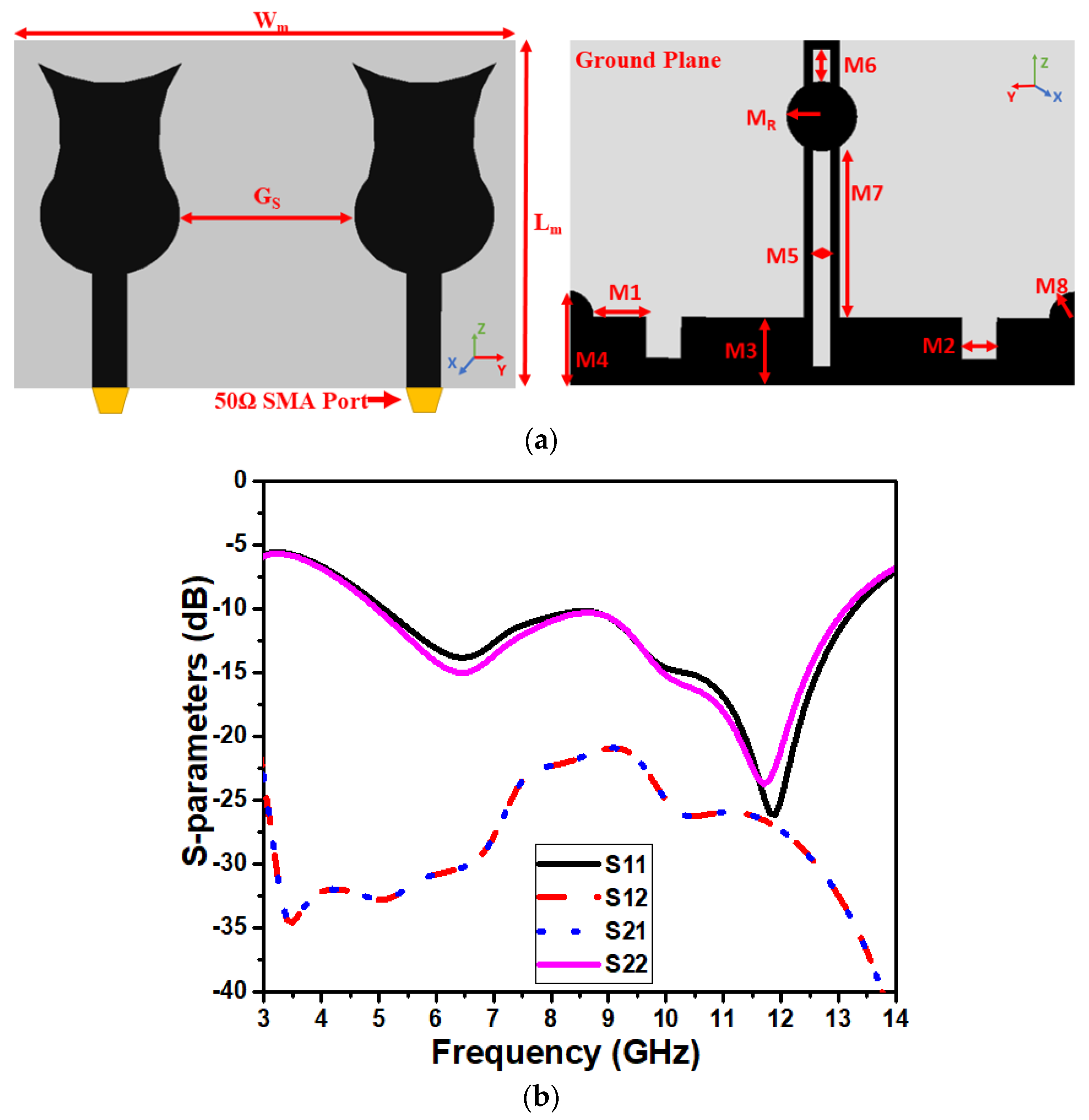
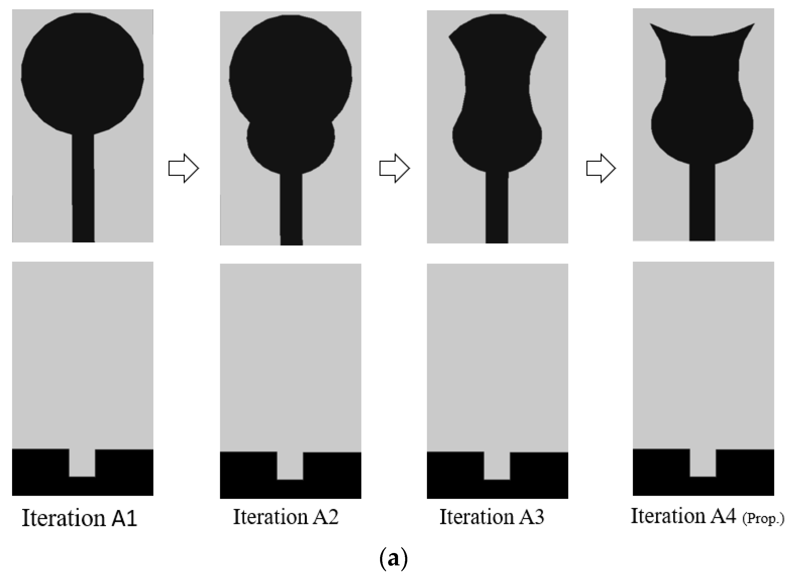
2. Antenna Design
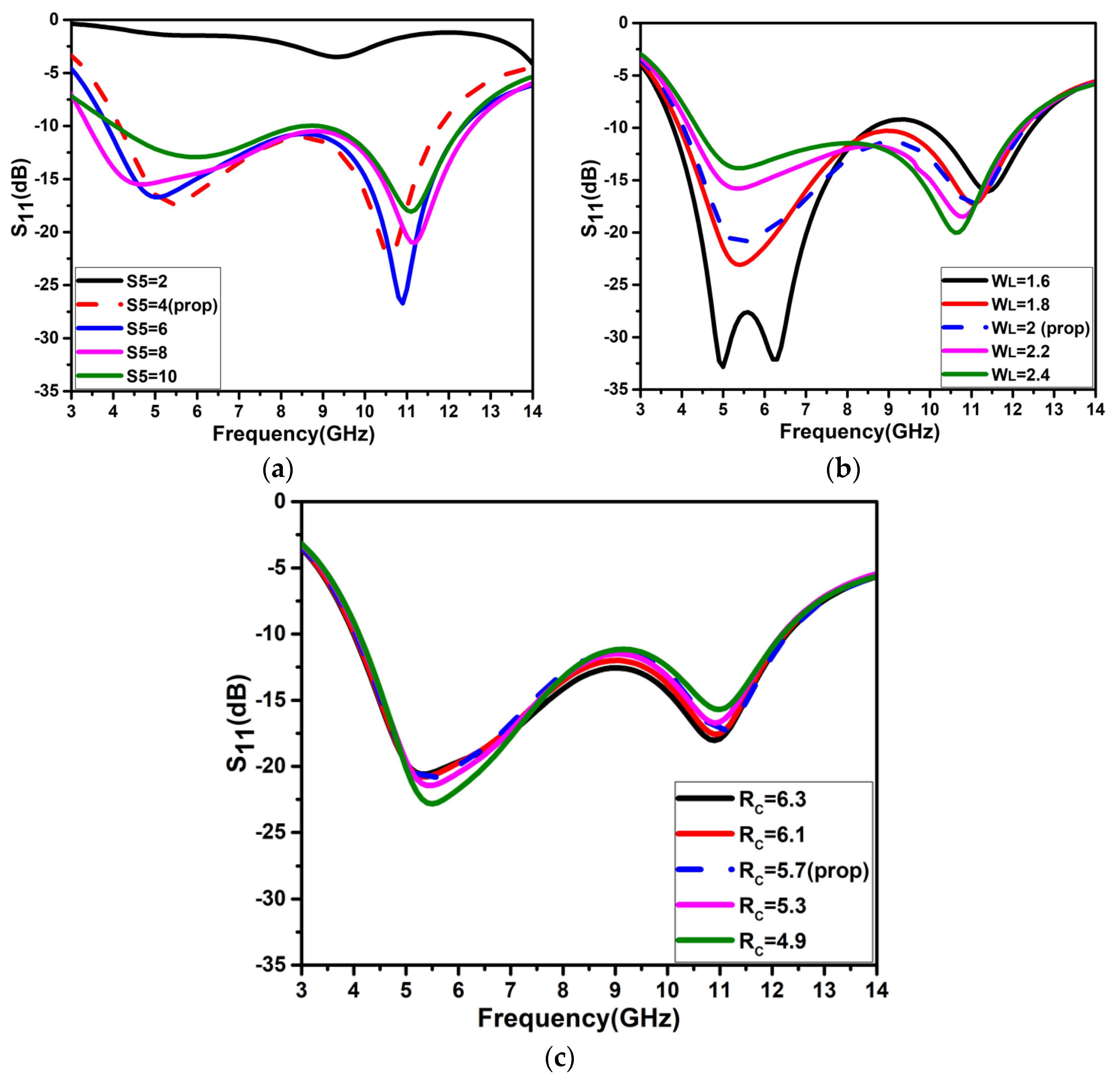
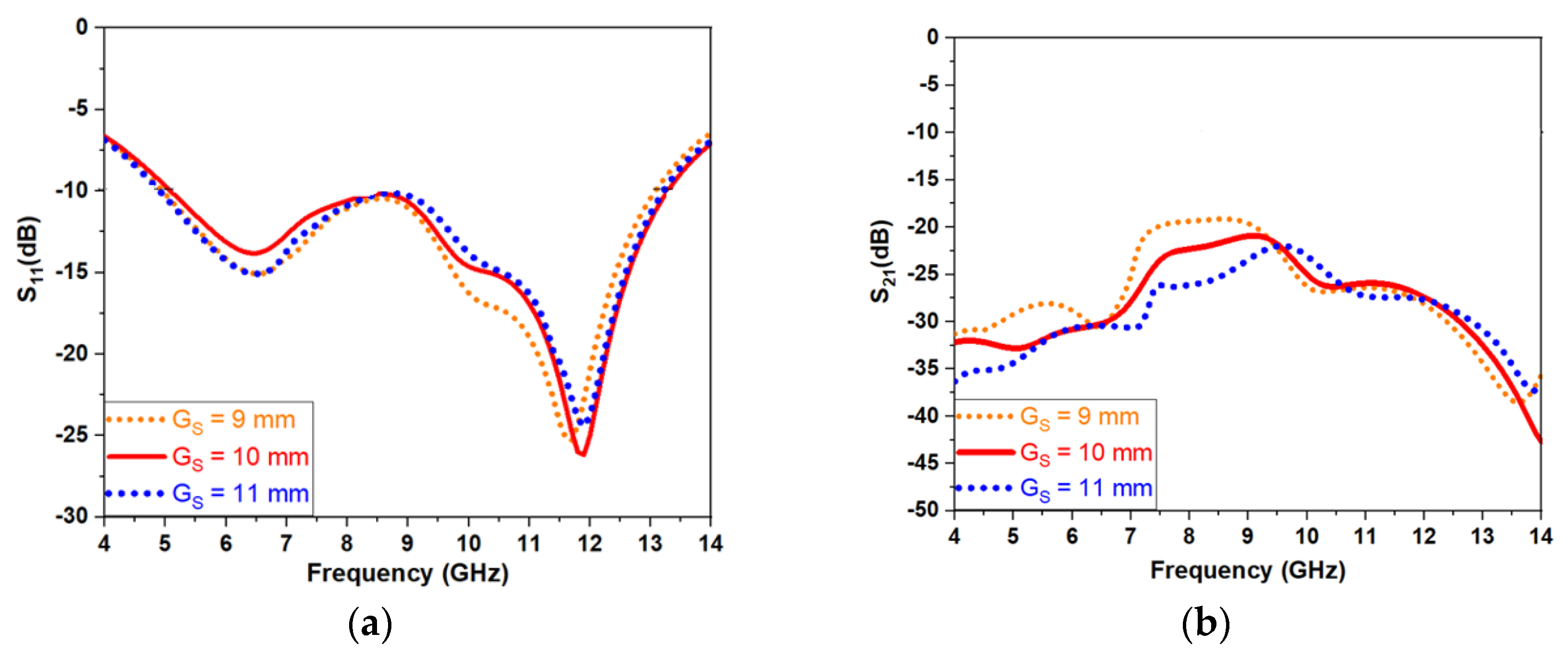
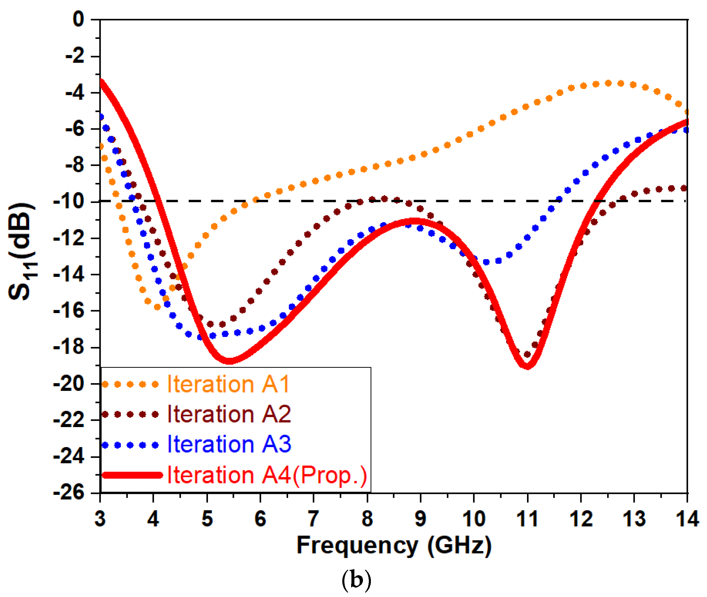
3. Parametric Analysis
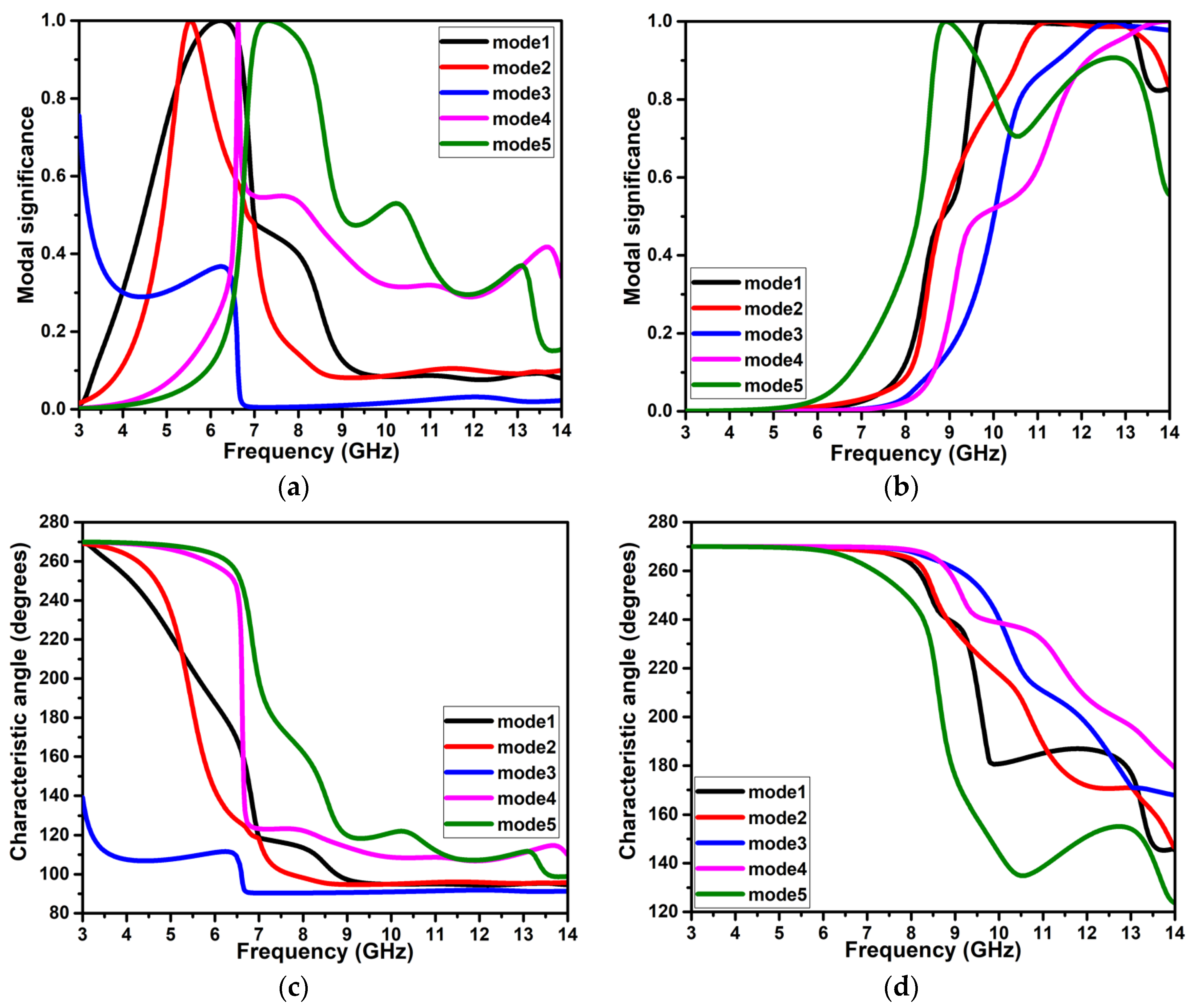
4. Characteristic Mode Analysis
5. Results and Discussion
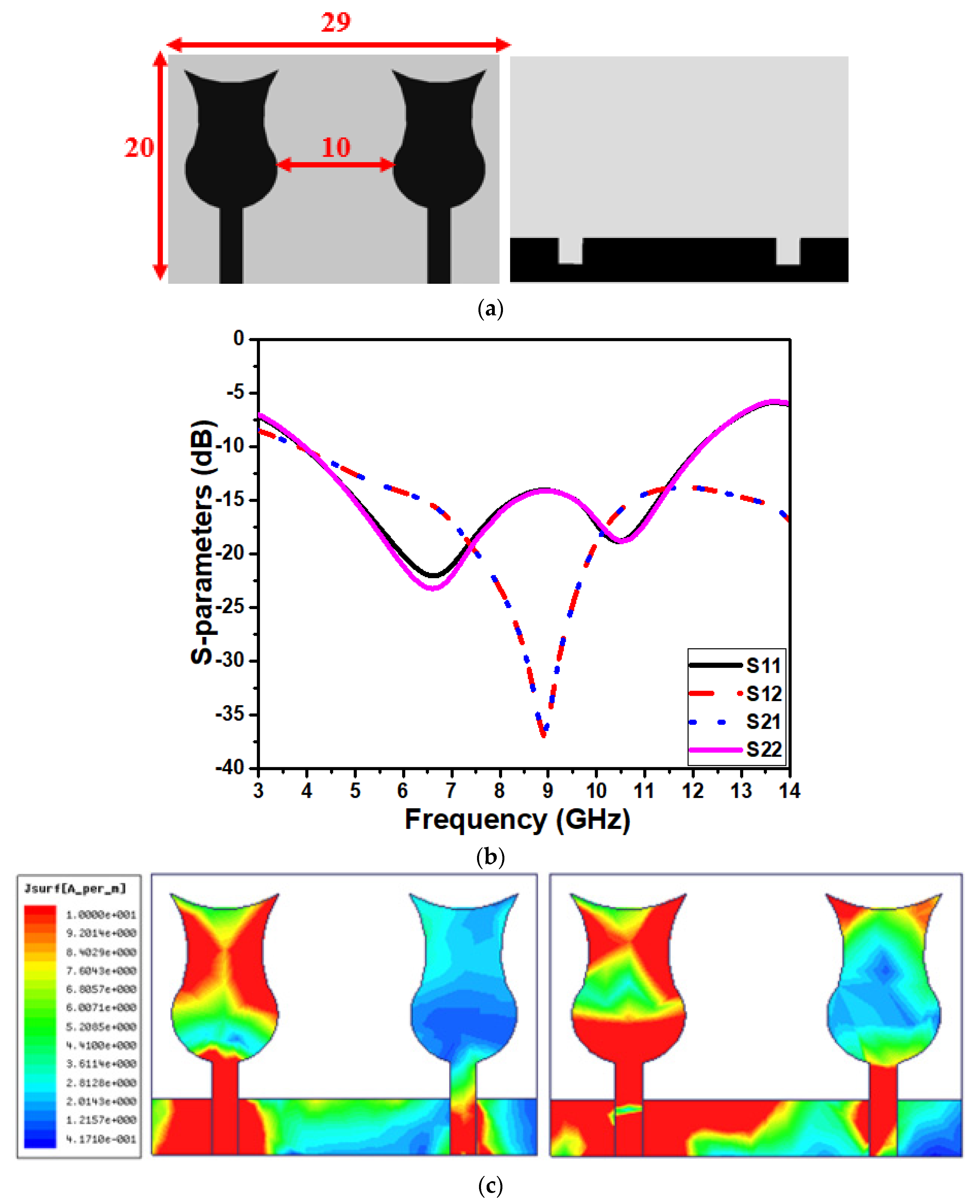
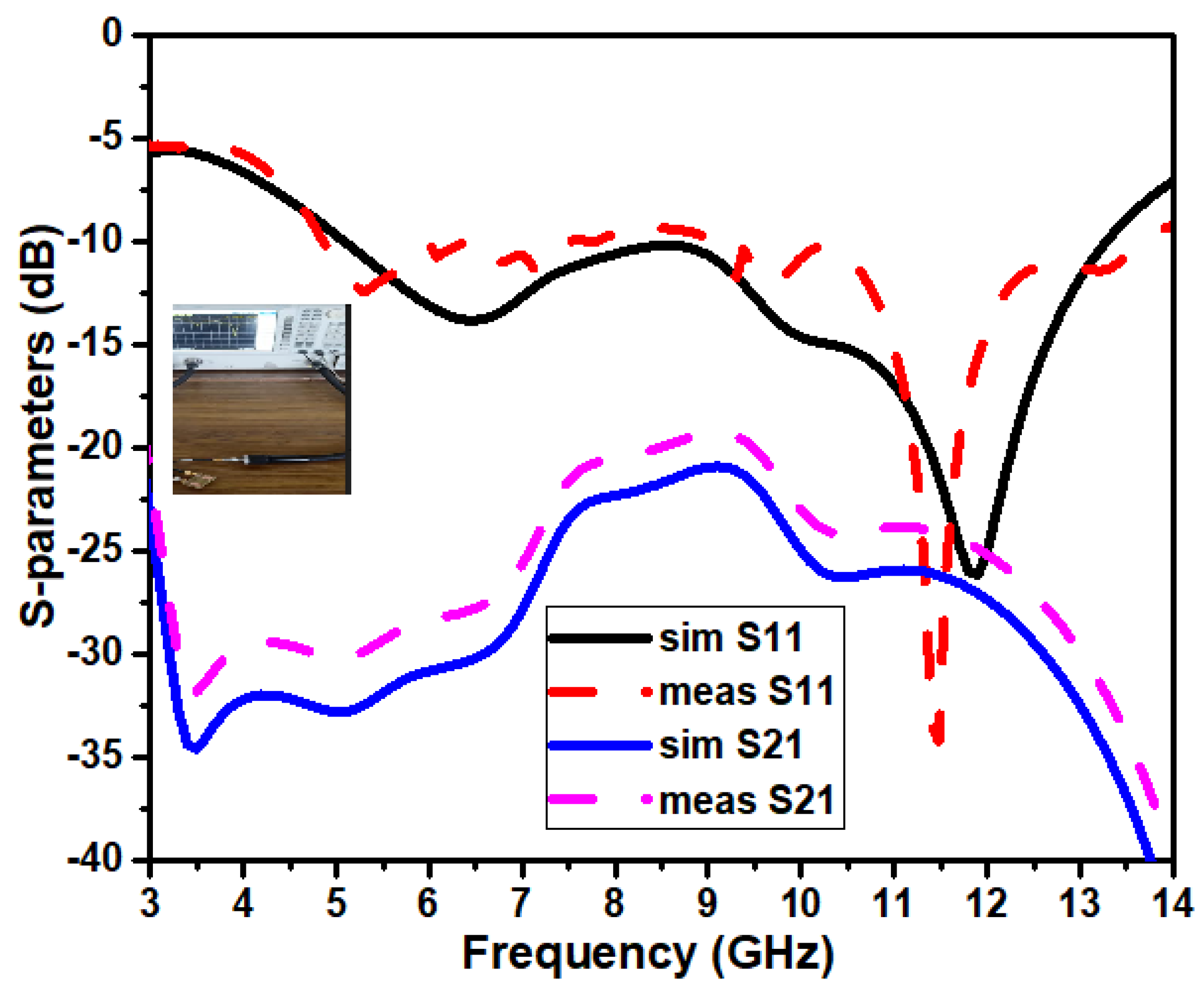
5.1. Scattering Parameters
5.2. Current Distribution
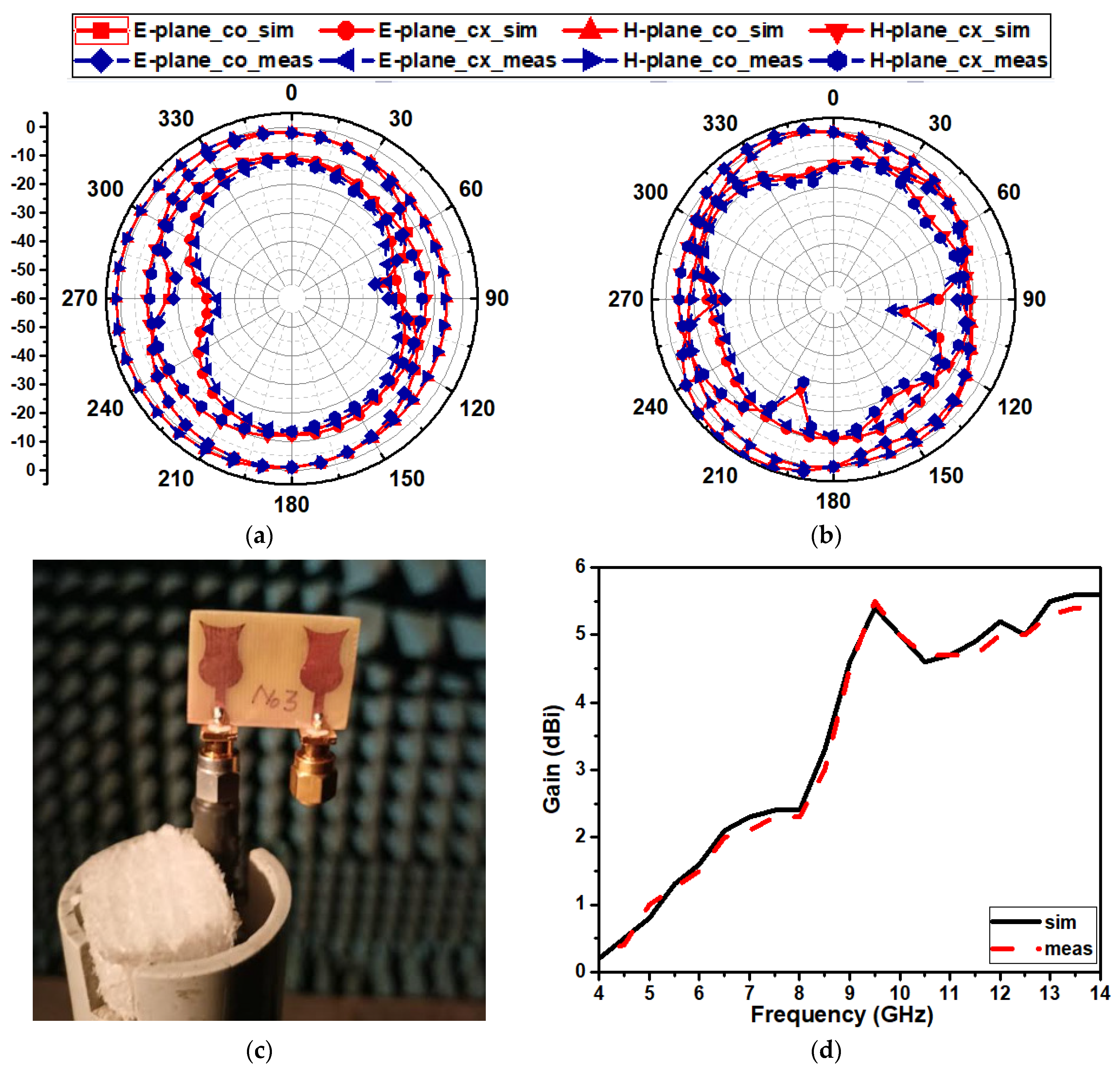
5.3. Radiation Properties
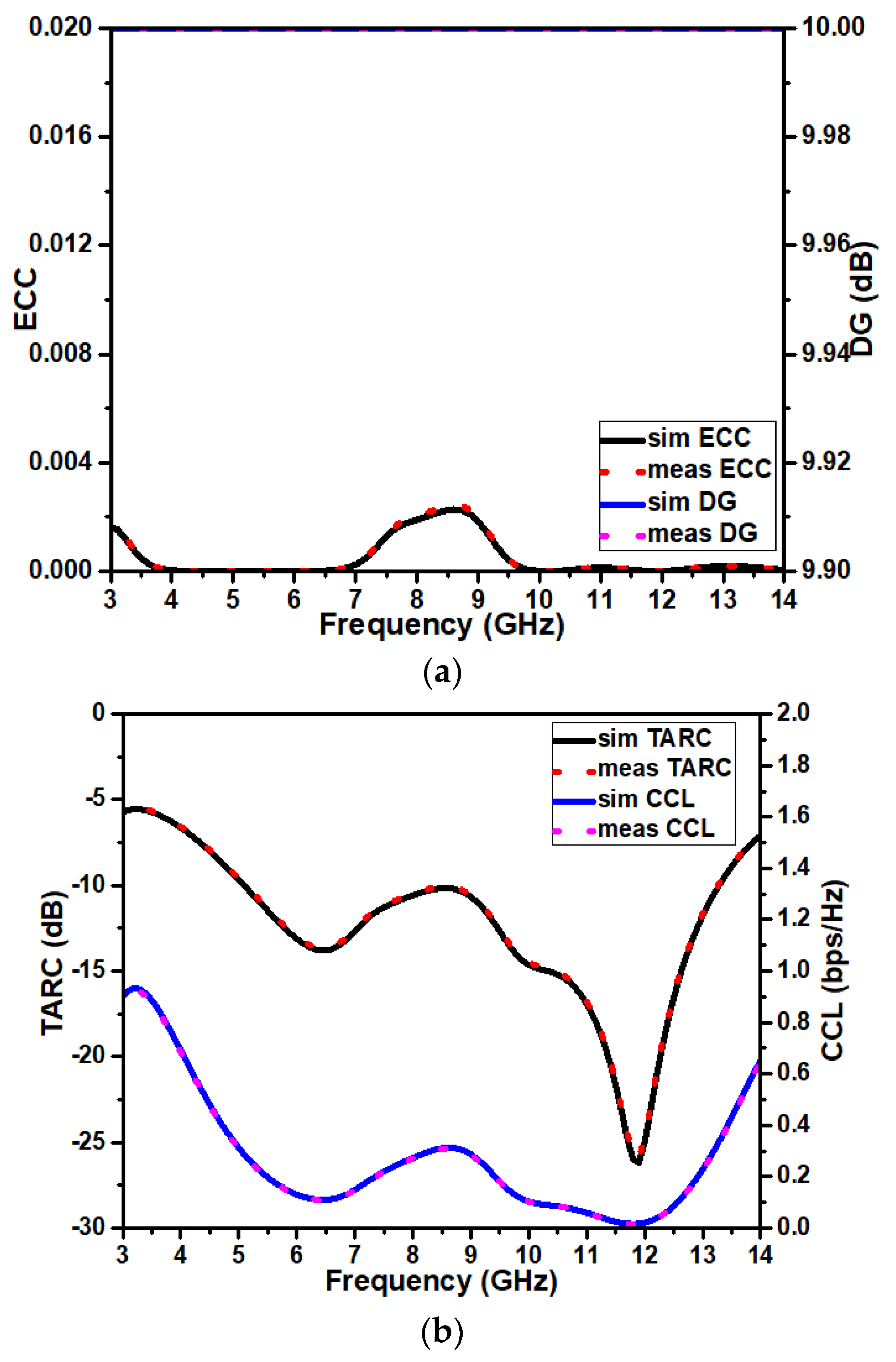
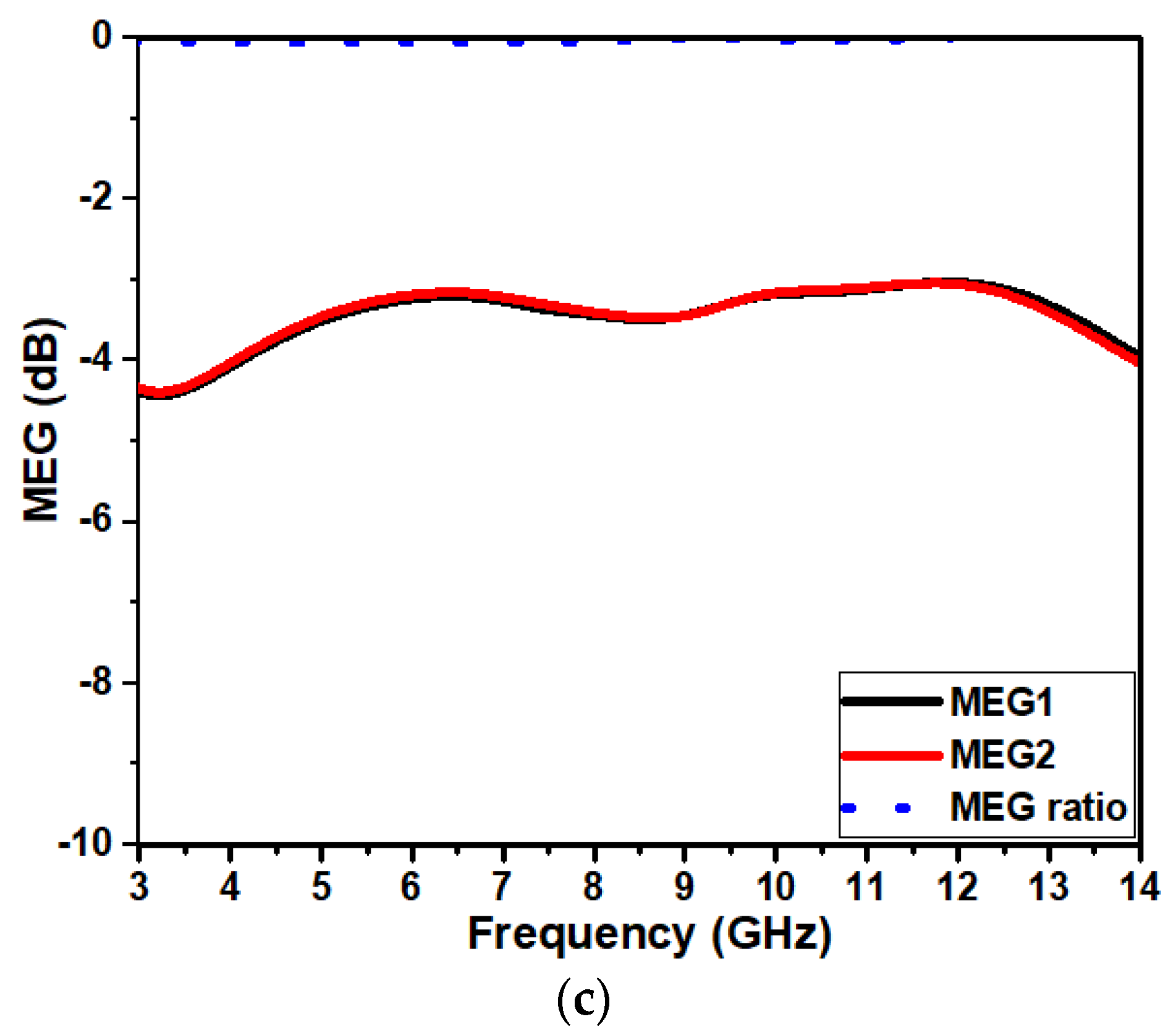
5.4. Diversity Features
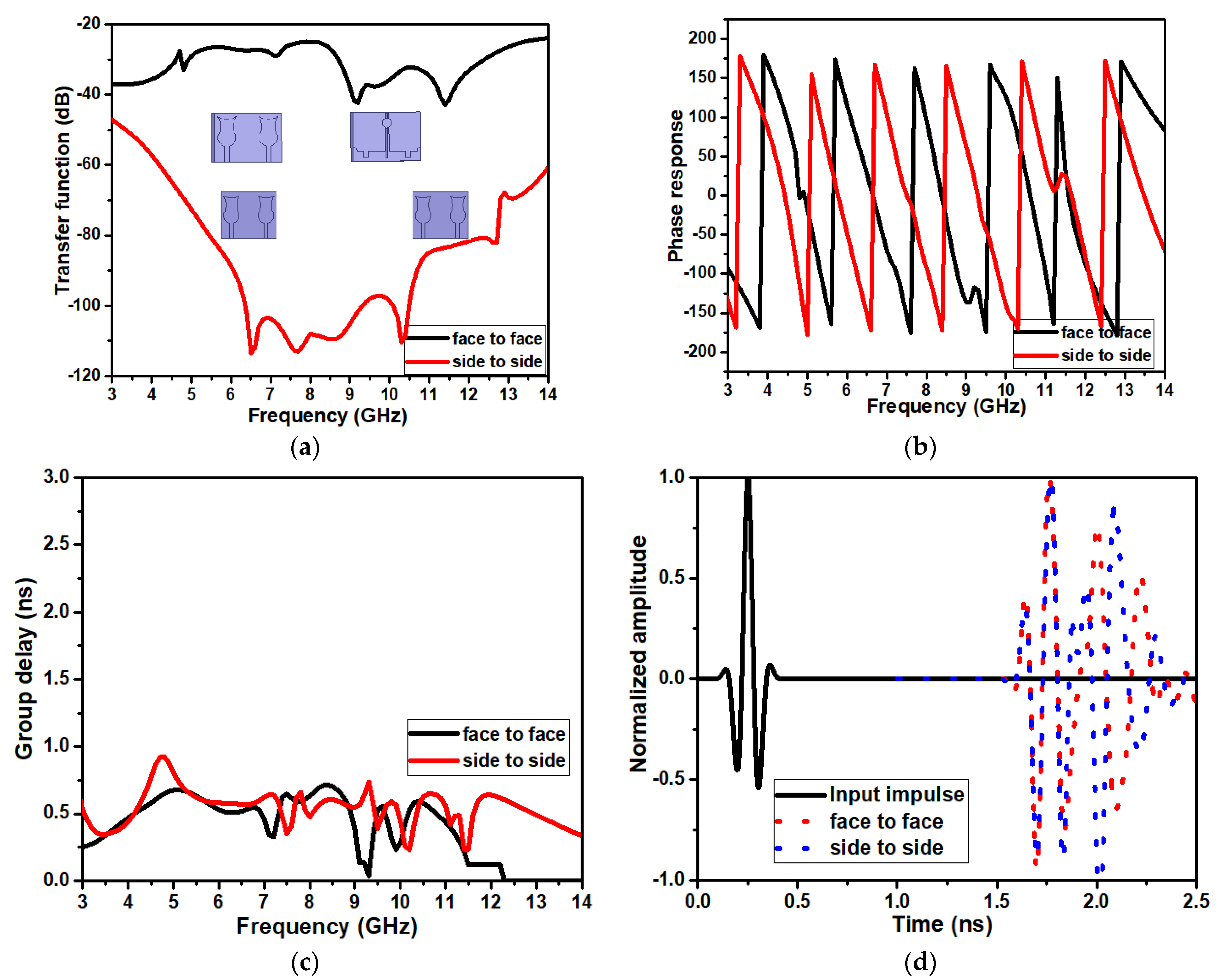
5.5. Time Domain Features
6. Comparative Analysis
7. Conclusions
Author Contributions
Funding
Data Availability Statement
Conflicts of Interest
References
- Galvan-Tejada, G.M.; Peyrot-Solis, M.A.; Aguilar, H.J. Ultra Wideband Antennas: Design, Methodologies, and Performance; CRC Press: Boca Raton, FL, USA, 2017. [Google Scholar]
- Chen, Z.N.; Chia, M.Y.W. Broadband Planar Antennas: Design and Applications; John Wiley & Sons: Hoboken, NJ, USA, 2006. [Google Scholar]
- Devana, V.K.R.; Satyanarayana, V.; Lakshmi, A.V.; Sukanya, Y.; Kumar, C.M.; Ponnapalli, V.P.; Jagadeesh Babu, K. A novel compact fractal UWB antenna with dual band notched characteristics. Analog. Integr. Circuits Signal Process. 2022, 110, 349–360. [Google Scholar] [CrossRef]
- Pandhare, R.A.; Abegaonkar, M.P.; Dhote, C. UWB antenna with novel FSS reflector for the enhancement of the gain and bandwidth. Int. J. Microw. Wirel. Technol. 2022, 14, 1353–1368. [Google Scholar] [CrossRef]
- Zaidi, A.; Awan, W.A.; Ghaffar, A.; Alzaidi, M.S.; Alsharef, M.; Elkamchouchi, D.H.; Ghoneim, S.S.; Alharbi, T.E. A low profile ultra-wideband antenna with reconfigurable notch band characteristics for smart electronic systems. Micromachines 2022, 13, 1803. [Google Scholar] [CrossRef] [PubMed]
- Uwiringiyimana, J.P.; Khayam, U.; Montanari, G.C. Design and implementation of ultra-wide band antenna for partial discharge detection in high voltage power equipment. IEEE Access 2022, 10, 10983–10994. [Google Scholar] [CrossRef]
- Saeidi, T.; Alhawari, A.R.; Almawgani, A.H.; Alsuwian, T.; Imran, M.A.; Abbasi, Q. High gain compact UWB antenna for ground penetrating radar detection and soil inspection. Sensors 2022, 22, 5183. [Google Scholar] [CrossRef]
- Abbas, A.; Hussain, N.; Sufian, M.A.; Jung, J.; Park, S.M.; Kim, N. Isolation and gain improvement of a rectangular notch UWB-MIMO antenna. Sensors 2022, 22, 1460. [Google Scholar] [CrossRef]
- Balaji, V.R.; Addepalli, T.; Desai, A.; Nella, A.; Nguyen, T.K. An inverted L-strip loaded ground with hollow semi-hexagonal four-element polarization diversity UWB-MIMO antenna. Trans. Emerg. Telecommun. Technol. 2022, 33, e4381. [Google Scholar] [CrossRef]
- Ahmed, B.T.; Rodríguez, I.F. Compact high isolation UWB MIMO antennas. Wirel. Netw. 2022, 28, 1977–1999. [Google Scholar] [CrossRef]
- Mu, W.; Lin, H.; Wang, Z.; Li, C.; Yang, M.; Nie, W.; Wu, J. A flower-shaped miniaturized UWB-MIMO antenna with high isolation. Electronics 2022, 11, 2190. [Google Scholar] [CrossRef]
- Sharawi, M.S. Current misuses and future prospects for printed multiple-input, multiple-output antenna systems [wireless corner]. IEEE Antennas Propag. Mag. 2017, 59, 162–170. [Google Scholar] [CrossRef]
- Kumar, P.; Pathan, S.; Vincent, S.; Kumar, O.P.; Yashwanth, N.; Kumar, P.; Shetty, P.R.; Ali, T. A Compact Quad-Port UWB MIMO Antenna with Improved Isolation Using a Novel Mesh-Like Decoupling Structure and Unique DGS. IEEE Trans. Circuits Syst. II Express Briefs 2023, 70, 949–953. [Google Scholar] [CrossRef]
- Kumar, P.; Ali, T.; Pai, M.M. A compact highly isolated two-and four-port ultrawideband Multiple Input and Multiple Output antenna with Wireless LAN and X-band notch characteristics based on Defected Ground Structure. Int. J. Commun. Syst. 2022, 35, e5331. [Google Scholar] [CrossRef]
- Kumar, P.; Pathan, S.; Kumar, O.P.; Vincent, S.; Nanjappa, Y.; Kumar, P.; Shetty, P.; Ali, T. Design of a Six-Port Compact UWB MIMO Antenna With a Distinctive DGS for Improved Isolation. IEEE Access 2022, 10, 112964–112974. [Google Scholar] [CrossRef]
- Garbacz, R.J. Modal expansions for resonance scattering phenomena. Proc. IEEE 1965, 53, 856–864. [Google Scholar] [CrossRef]
- Garbacz, R.; Turpin, R. A generalized expansion for radiated and scattered fields. IEEE Trans. Antennas Propag. 1971, 19, 348–358. [Google Scholar] [CrossRef] [Green Version]
- Austin, B.A.; Murray, K.P. The application of characteristic-mode techniques to vehicle-mounted NVIS antennas. IEEE Antennas Propag. Mag. 1998, 40, 7–21. [Google Scholar] [CrossRef]
- Kim, J.; Qu, L.; Jo, H.; Zhang, R.; Kim, H. A MIMO antenna design based on the characteristic mode. Microw. Opt. Technol. Lett. 2017, 59, 893–898. [Google Scholar] [CrossRef]
- Adams, J.J.; Genovesi, S.; Yang, B.; Antonino-Daviu, E. Antenna Element Design Using Characteristic Mode Analysis: Insights and research directions. IEEE Antennas Propag. Mag. 2022, 64, 32–40. [Google Scholar] [CrossRef]
- Zhu, J.; Li, S.; Feng, B.; Deng, L.; Yin, S. Compact dual-polarized UWB quasi-self-complementary MIMO/diversity antenna with band-rejection capability. IEEE Antennas Wirel. Propag. Lett. 2015, 15, 905–908. [Google Scholar] [CrossRef]
- Deng, J.Y.; Guo, L.X.; Liu, X.L. An ultrawideband MIMO antenna with a high isolation. IEEE Antennas Wirel. Propag. Lett. 2015, 15, 182–185. [Google Scholar] [CrossRef]
- Iqbal, A.; Saraereh, O.A.; Ahmad, A.W.; Bashir, S. Mutual coupling reduction using F-shaped stubs in UWB-MIMO antenna. IEEE Access 2017, 6, 2755–2759. [Google Scholar] [CrossRef]
- Srivastava, G.; Mohan, A. Compact MIMO slot antenna for UWB applications. IEEE Antennas Wirel. Propag. Lett. 2015, 15, 1057–1060. [Google Scholar] [CrossRef]
- Jabire, A.H.; Ghaffar, A.; Li, X.J.; Abdu, A.; Saminu, S.; Alibakhshikenari, M.; Falcone, F.; Limiti, E. Metamaterial based design of compact UWB/MIMO monopoles antenna with characteristic mode analysis. Appl. Sci. 2021, 11, 1542. [Google Scholar] [CrossRef]
- Nie, L.Y.; Lin, X.Q.; Xiang, S.; Wang, B.; Xiao, L.; Ye, J.Y. High-isolation two-port UWB antenna based on shared structure. IEEE Trans. Antennas Propag. 2020, 68, 8186–8191. [Google Scholar] [CrossRef]
- Wang, L.; Du, Z.; Yang, H.; Ma, R.; Zhao, Y.; Cui, X.; Xi, X. Compact UWB MIMO antenna with high isolation using fence-type decoupling structure. IEEE Antennas Wirel. Propag. Lett. 2019, 18, 1641–1645. [Google Scholar] [CrossRef]
- Agarwal, M.; Dhanoa, J.K.; Khandelwal, M.K. Two-port hexagon shaped MIMO microstrip antenna for UWB applications integrated with double stop bands for WiMax and WLAN. AEU-Int. J. Electron. Commun. 2021, 138, 153885. [Google Scholar] [CrossRef]


| W | L | Wp | Lp | P1 | Rc | FL | WL | S1 | S2 | S3 | S4 | S5 |
|---|---|---|---|---|---|---|---|---|---|---|---|---|
| 20 | 11 | 8.2 | 11.8 | 2.8 | 5.7 | 6.6 | 2 | 4.5 | 2.3 | 2 | 4.5 | 4 |
| Wm | Lm | Gs | M1 | M2 | M3 | M4 | M5 | M6 | M7 | M8 | MR |
|---|---|---|---|---|---|---|---|---|---|---|---|
| 29 | 20 | 10 | 3 | 2 | 4 | 5.5 | 1 | 2.2 | 9.7 | 1.5 | 2 |
| Significance | ||
|---|---|---|
| Electric energy | ||
| Resonating point | ||
| Magnetic energy |
| Ref | Techniques Used | Dimension (mm3) | Impedance BANDWIDTH (BW) (GHz)/Fractional BW % | Peak Gain (dBi) | Isolation (dB) | ECC | DG | MEG | TARC | CCL |
|---|---|---|---|---|---|---|---|---|---|---|
| [21] | Orthogonal | 35 × 35 × 1 | 3–12/120 | 4.6 | >20 | <0.3 | - | <−3 | - | - |
| [22] | Parasitic elements | 30 × 40 × 0.8 | 3.1–10.6/109 | - | >15 | <0.15 | - | - | - | - |
| [23] | DGS | 50 × 30 × 1.6 | 2.5–14.5/141 | 4.3 | >20 | <0.04 | >7.4 | - | - | - |
| [24] | DGS | 36 × 18 × 1.6 | 3.2–12/115 | 4 | >22 | <0.01 | - | - | - | <0.4 |
| [25] | DGS | 30 × 30 × 1.6 | 2.6–12/128 | 5.5 | >20 | <0.01 | - | - | - | - |
| [26] | Coplanar waveguide | 50 × 60 × 1.6 | 2.98–10/108 | 2.5 | >31.4 | <0.5 | ≈ 10 | - | - | - |
| [27] | DGS | 35 × 50 × 1.6 | 3–11/114 | 5.5 | >25 | <0.004 | - | - | - | - |
| [28] | DGS | 35 × 46 × 1.6 | 2.1–11.4/137 | 1.5 | >15 | <0.04 | ≈ 10 | - | - | - |
| proposed | DGS | 20 × 29 × 1.6 | 5–13.5/92 | 5.5 | >21 | <0.002 | ≈ 10 | <−3 | <−10 | <0.3 |
Disclaimer/Publisher’s Note: The statements, opinions and data contained in all publications are solely those of the individual author(s) and contributor(s) and not of MDPI and/or the editor(s). MDPI and/or the editor(s) disclaim responsibility for any injury to people or property resulting from any ideas, methods, instructions or products referred to in the content. |
© 2023 by the authors. Licensee MDPI, Basel, Switzerland. This article is an open access article distributed under the terms and conditions of the Creative Commons Attribution (CC BY) license (https://creativecommons.org/licenses/by/4.0/).
Share and Cite
Kempanna, S.B.; Biradar, R.C.; Kumar, P.; Kumar, P.; Pathan, S.; Ali, T. Characteristic-Mode-Analysis-Based Compact Vase-Shaped Two-Element UWB MIMO Antenna Using a Unique DGS for Wireless Communication. J. Sens. Actuator Netw. 2023, 12, 47. https://doi.org/10.3390/jsan12030047
Kempanna SB, Biradar RC, Kumar P, Kumar P, Pathan S, Ali T. Characteristic-Mode-Analysis-Based Compact Vase-Shaped Two-Element UWB MIMO Antenna Using a Unique DGS for Wireless Communication. Journal of Sensor and Actuator Networks. 2023; 12(3):47. https://doi.org/10.3390/jsan12030047
Chicago/Turabian StyleKempanna, Subhash Bodaguru, Rajashekhar C. Biradar, Praveen Kumar, Pradeep Kumar, Sameena Pathan, and Tanweer Ali. 2023. "Characteristic-Mode-Analysis-Based Compact Vase-Shaped Two-Element UWB MIMO Antenna Using a Unique DGS for Wireless Communication" Journal of Sensor and Actuator Networks 12, no. 3: 47. https://doi.org/10.3390/jsan12030047