Article

Sensorless Estimation of Human Joint Torque for Robust Tracking Control of Lower-Limb Exoskeleton Assistive Gait Rehabilitation

by
Auwalu Muhammad Abdullahi
and
Ronnapee Chaichaowarat
*
International School of Engineering, Chulalongkorn University, 254 Phayathai Road, Pathumwan, Bangkok 10330, Thailand
*
Author to whom correspondence should be addressed.
J. Sens. Actuator Netw. 2023, 12(4), 53; https://doi.org/10.3390/jsan12040053
Submission received: 17 May 2023 / Revised: 25 June 2023 / Accepted: 5 July 2023 / Published: 7 July 2023
(This article belongs to the Special Issue Reliability Improvement for Acquired Human Signals)

Abstract

:
Patients suffering from motor disorders or weakness resulting from either serious spinal cord injury or stroke often require rehabilitation therapy to regain their mobility. In the lower limbs, exoskeletons have two motors aligned with the patients’ hip and knee to assist in rehabilitation exercises by supporting the patient’s body structure to increase the torques at the hip and knee joints. Assistive rehabilitation is, however, challenging, as the human torque is unknown and varies from patient to patient. This poses difficulties in determining the level of assistance required for a particular patient. In this paper, therefore, a modified extended state observer (ESO)-based integral sliding mode (ISM) controller (MESOISMC) for lower-limb exoskeleton assistive gait rehabilitation is proposed. The ESO is used to estimate the unknown human torque without application of a torque sensor while the ISMC is used to achieve robust tracking of preset hip and knee joint angles by considering the estimated human torque as a disturbance. The performance of the proposed MESOISMC was assessed using the mean absolute error (MAE). The obtained results show an 85.02% and 87.38% reduction in the MAE for the hip and joint angles, respectively, when the proposed MESOISMC is compared with ISMC with both controllers tuned via LMI optimization. The results also indicate that the proposed MESOISMC method is effective and efficient for user comfort and safety during gait rehabilitation training.

1. Introduction

Exoskeletons are important neuron-engineering devices used for rehabilitation of patients suffering from loss of motor torque at their joints due to spinal cord injuries, disabilities, or stroke. Two types of exoskeletons are used for rehabilitation of patients to regain mobility. The first type is full assistive-type exoskeleton, and, mainly, this type is used for people with serious spinal cord injury or those who are completely paralyzed [1,2]. In this case, the exoskeleton is responsible for providing the total torque required for patient movement and implies that the patient’s joints are passive. Such systems can be easily controlled as the total actuator torque is generated by the exoskeleton. The second type is the assistive-type exoskeleton, which is mostly used for patients with disabilities, who are aging, or who have weaker torque than is required for complete movement. Assistive-type exoskeletons can also be used to support healthy people, like cyclists or military personnel, to increase their load-carrying capacity [3,4]. Exoskeletons provide external support to the body structure, and thus, athletes and military personnel can use exoskeletons to reduce stress fractures or chronic stress in the tibia fibula regions.
Several studies have been conducted on assistive exoskeletons. An active power-assisted lower limb exoskeleton was presented in [5], where the device was designed to measure thigh torque in real time to improve the random movement of patient lower limbs. An unpowered exoskeleton that used kinematic and dynamic extension for human gait training was proposed [6]. Biomechanics of stair ascent (knee angle and moment) were shown on the passive knee exoskeleton using brake torque and passive knee exoskeleton using torsion spring [7,8]. Another study presented impedance modulation using an electromagnetic brake [9]. Several other methods have been used for human–exoskeleton force estimation, and some for rehabilitation of patients [10,11,12,13].
This work focusses mainly on human torque estimation of the human–exoskeleton system. Since the magnitude of human joint torque applied is unknown, estimation of human joint torque magnitude is critical, particularly in the control of assistive-type exoskeletons. Two methods are mainly used for human torque estimation in the literature: electromyography (EMG) and inverse dynamics methods [14]. EMG signals have been used in several research works to control assistive robots and estimate the human torque [14,15,16,17,18]. Another type is electroencephalography (EEG), which is used to estimate the brain’s motor activity in real time. Thus, prediction of a motion plan for rehabilitation of patients with motor disorders can be effectively achieved using EEG [19]. In addition, mechanomyography has been used in some applications [20]. Similarly, there are a number of studies conducted to estimate human torque using the inverse dynamics method [21,22,23,24]. Furthermore, in other studies, disturbance observers were implemented in robot control. In general, the disturbance observer is used to estimate unknown external or uncertain torque disturbance without additional sensors [25]. Other methods have also been implemented for rehabilitation of patients using exoskeletons for walking rehabilitation [26,27,28,29]. These works introduced techniques to modulate intrinsic properties of high-force linear actuators for active body-weight support systems for gait rehabilitation. Furthermore, neural networks were also used for optimization of human–exoskeleton interaction during the rehabilitation process. Most of the methods used for gait prediction modeling failed to consider environmental changes, which can be efficiently handled using neural networks [30,31,32].
Sliding mode control (SMC) has been extensively used in robotics for disturbance rejection and as observer in rehabilitation robots. SMC was presented in a considerable number of studies for estimation of torque/force in robotics [33,34,35]. Super-twisting SMC was introduced for position and stiffness control of elastic actuators with input delay [36]. Extended state observers (ESOs) have also been used for estimation of unknown system parameters. There are several works presented on estimation of unknown exoskeleton parameters [37,38,39]. In addition, admittance controls for torque estimation were presented in [40,41]. Other methods have also been implemented for rehabilitation of patients using exoskeleton for walking rehabilitation [42,43,44]. Integral sliding mode robust control has been used in many studies to determine the rejection of matched and unmatched disturbance and system uncertainties [45,46].
Human torque estimation remains a challenging task in gait rehabilitation control. This work, therefore, proposes a modified ESO-based integral SMC (MESOISMC). The motivation behind the cascade control of ISMC and ESO is based on the need for adequate, precise estimation and cancelation of effect of the unknown human torque. Any error in the estimation will cause improper coordination to aligned motion of the exoskeleton joint motors and the actual human hip/knee joints. This can cause serious damage to the system and might also injure the wearer. Thus, the combined advantages of ESO in the estimation of lumped disturbances (unknown parameter and model uncertainties) and rejection capabilities of ISMC of both matched and unmatched disturbances is the main motivation of this work. The integral SMC (ISMC) was designed to cancel the effects of human joint torque estimated by the ESO. Since the magnitude of human joint torque is unknown, it will be estimated and its effect will be cancelled in this work. Therefore, the total joint torque for the intended motion will be provided by the exoskeleton. Considering the unknown human torque as a disturbance in this work implies that the total torque required for the intended patient mobility will be provided by the exoskeleton. Moreover, a modification was made to the nonlinear control design by introducing the weighted estimated error from the ESO in the equivalent control part of the ISMC design. This novel design approach, combined with the advantages of the ISMC and ESO, significantly improve the performance of the exoskeleton system by reducing the error in reference trajectory tracking of human joints. The rest of the paper is organized as follows. Section 2 introduces the human–exoskeleton model and integral sliding mode control design concept. Section 3 presents the design of the proposed MESOISMC. Section 4 describes the implementation of the proposed controller using the MATLAB Simulation toolbox. Section 5 presents the results and discussions of the proposed control performance. Section 6 draws a conclusion based on the research findings.

2. Human–Exoskeleton Model and Control Design

This section presents a dynamic model of the human exoskeleton and control design. Under the control design, an integral sliding mode control will be presented.

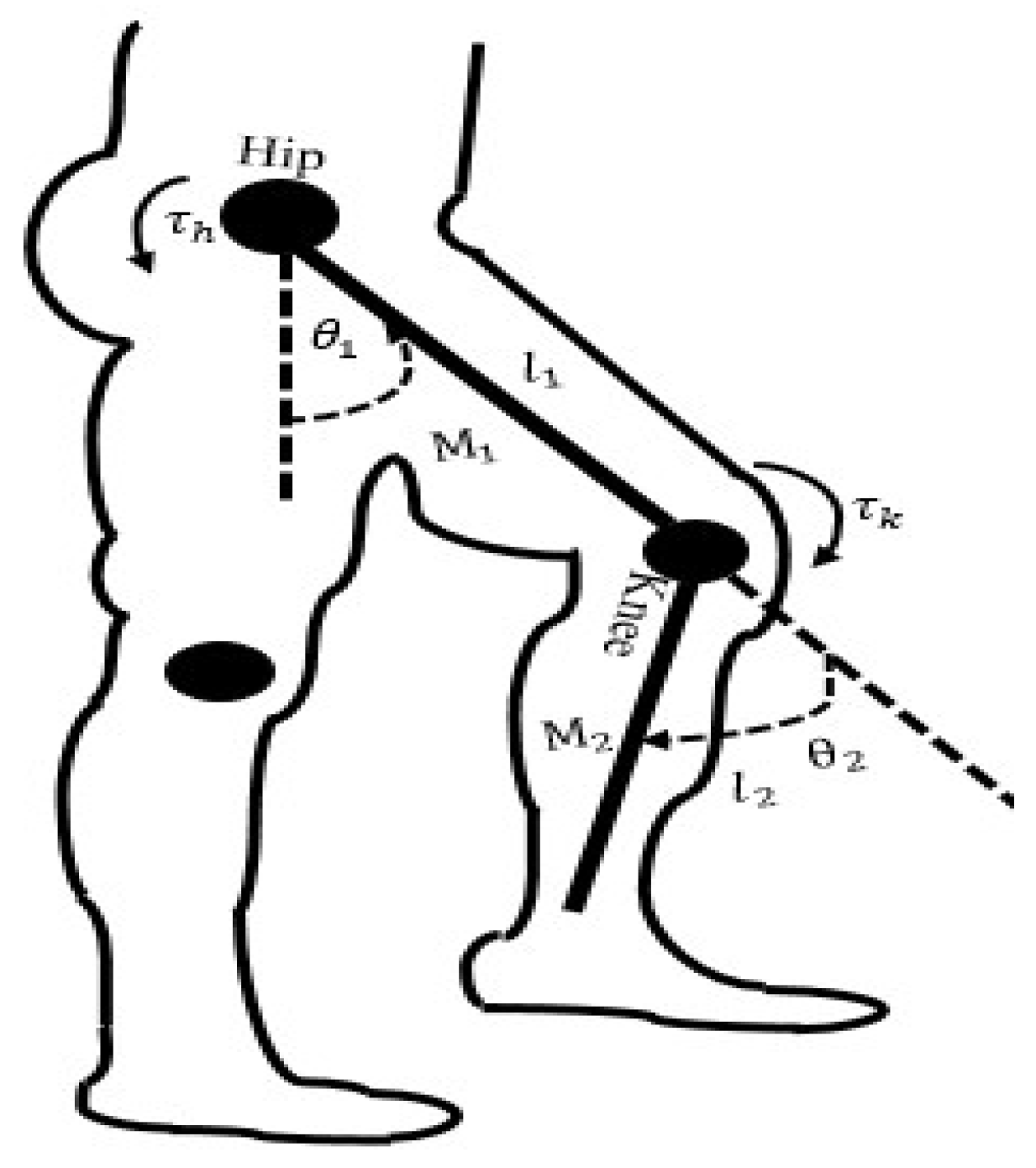
2.1. Dynamic Model of Human Exoskeleton

The dynamic model of human exoskeleton used in this work is as presented in [47]. The unified general form of the nonlinear dynamic model for hip–knee lower limbs of human leg for stance and swing is given as follows:
M θ θ ¨ + C θ , θ ˙ θ ˙ + G θ = τ r + τ h
where M is the mass, moment of inertia, thigh, and shank link matrix of the hip–knee model, C is centrifugal force and Coriolis force, and G contains the gravitational term. The terms τ r and τ h are the exoskeleton and human torque, respectively. The human torque is unknown and difficult to measure for a particular intended motion. Therefore, in this work, human torque is considered as disturbance and is lumped with system uncertainties since, for this type of system, uncertainties are rare, and the exoskeleton torque is the input of the system. Hence, the dynamic hip–knee model in Equation (1) can be rewritten as follows:
θ ¨ t = b C θ , θ ˙ G θ + b u r t + b ϕ t
where ϕ t = τ h , b = M 1 , and u r t = τ r . Note that ϕ t is a lumped human torque with system uncertainties at the hip–knee joints. Similarly, the human torque can be represented from Equation (1) as follows:
τ h = M θ θ ¨ + C θ , θ ˙ θ ˙ + G θ τ r
Equation (3) represents the dynamic formulated lumped human torque from the system dynamics, which can also be represented as the following:
ϕ t = M θ θ ¨ + C θ , θ ˙ θ ˙ + G θ u r t
The total torque was computed using the equation below:
τ t = τ r t + τ h t
The total control signal is u t , which is equivalent to the total applied torque τ t . Therefore, by estimating and cancelling the effects of the human torque, the exoskeleton torque would be the resultant torque that enters the system, which is given as follows:
τ r t = u t ϕ t
The human exoskeleton for hip and knee joint rehabilitation used in this work is shown in Figure 1.
From Equation (1), the simplified nonlinear models of the hip and knee are as follows:
τ h i p = 1 3 M 1 l 1 2 + M 2 l 1 2 θ ¨ 1 + 1 2 M 2 l 1 l 2 cos θ 2 θ 1 θ ¨ 2 1 2 M 2 l 1 l 2 sin θ 2 θ 1 θ ˙ 2 2 + l 1 g sin θ 1 1 2 M 1 + M 2
τ k n e e = 1 2 M 2 l 1 l 2 cos θ 2 θ 1 θ ¨ 1 + 1 3 M 2 l 2 2 θ ¨ 2 + 1 2 M 2 l 1 l 2 sin θ 2 θ 1 θ ˙ 1 2 + M 2 g l 2 2 sin θ 2
where M 1 = m h u m a n T h i g h + m e x o T h i g h is the sum of human and exoskeleton thigh masses, and M 2 = m h u m a n S h a n k + m e x o S h a n k   is the sum of human and exoskeleton shank masses.
For the design of the equivalent control gain of the MESOISMC, the nonlinear model was linearized based on the assumption that, as hip/knee angles θ 1 / θ 2 approach zero, the cos θ 1 1 ,   cos θ 2 1 ,   sin θ 1 θ 1 ,   sin θ 1 sin θ 2 0 ,   θ ˙ 1 θ ˙ 2 0 , θ ˙ 1 2 0 , and θ ˙ 2 2 0 . Through simplification and re-arrangement, the linearized models of the hip–knee angles were given as follows:
θ ¨ 1 = τ h i p / 1 3 M 1 l 1 2 + M 2 l 1 2 l 1 g θ 1 1 2 M 1 + M 2 / 1 3 M 1 l 1 2 + M 2 l 1 2
θ ¨ 2 = τ k n e e / 1 3 M 2 l 2 2 M 2 g l 2 2 θ 2 / 1 3 M 2 l 2 2
The state space can be obtained from Equations (42) and (43) as follows:
x ˙ 1 t = x 2 t = θ ˙ 1 x ˙ 2 t = θ ¨ 1 = τ h i p / 1 3 M 1 l 1 2 + M 2 l 1 2 l 1 g θ 1 1 2 M 1 + M 2 / 1 3 M 1 l 1 2 + M 2 l 1 2 x ˙ 3 t = x 4 t = θ ˙ 2 x ˙ 4 t = θ ¨ 2 = τ k n e e / ( 1 3 M 2 l 2 2 M 2 g l 2 2 θ 2 / 1 3 M 2 l 2 2
The state space models of the dynamics of the human exoskeleton are presented as follows:
x ˙ t = A x t + B u t y t = C x t + D u t
where A, B, C, D, x, u and y are the state matrix, input matrix, output matrix, feed-forward matrix, state vector, input and output respectively. The state space matrices of the combined hip–knee joints are as follows:
A = 0 1 0 0 A 12 0 0 0 0 0 0 1 A 14 0 0 0     B = 0 0 b 01 0 0 0 0 b 02 , C = 1 0 0 0 0 1 0 0 0 0 1 0 0 0 0 1 D = 0 0 0 0 A 12 = l 1 g θ 1 1 2 M 1 + M 2 1 3 M 1 l 1 2 + M 2 l 1 2 A 14 = M 2 g l 2 2 θ 2 1 3 M 2 l 2 2 b 01 = τ h i p 1 3 M 1 l 1 2 + M 2 l 1 2 b 02 = τ k n e e 1 3 M 2 l 2 2
And state vector, x = θ 1 θ ˙ 1 θ 2 θ ˙ 2 T . The state space can be broken into hip and knee joint state spaces for controller design because each joint has a separate motor with a different torque.
A h i p = 0 1 A 12 h i p 0 B = 0 b 01 , C = 1 0 0 1 , D = 0 0 A k n e e = 0 1 A 14 k n e e 0 B = 0 b 02 , C = 1 0 0 1 , D = 0 0
Note that the linear model was only used for the design of the controller gains but, during the implementation, the nonlinear model was used in the simulation block.

2.2. Integral Sliding Mode Control (ISMC) Design

The ISMC is a well-known robust control for the rejection of matched and unmatched disturbances and system model uncertainties. The ISMC was designed as presented in [45,46]. In general, the control law of ISMC is given by the following:
u t = u e q t + u s w t
where u e q t and u s w t are the equivalent and switching controls, respectively. By substituting Equation (6) in Equation (15), the exoskeleton torque can be computed.
τ r t = u e q t + u s w t ϕ t
The equivalent control is the control in the absence of disturbances, and the switching or discontinuous control switches and maintains the state on the sliding surface in the presence of disturbance to guarantee sliding mode. Figure 2 shows the ISMC control block diagram used in this work.
In this work, for the ISMC design, the equivalent control is given as follows:
u e q t = K x t + N r t
where K is designed using a pole placement control method in this work, and N is a scaling factor. x t and r t are the system states and reference input, respectively.
Similarly, the switching control is selected using the following:
u s w t = Γ t tan h s t
where the term Γ t is a positive function and assumed to be the maximum value of the bounded disturbance signal given by Γ t   ϕ m a x t . The hyper tangent tanh function replaced the signum function s i g n , which is generally used in the design of switching control to reduce chattering. Therefore, total control signal in Equation (15) was computed as follows:
u t = K x t + N r t Γ t tanh s t
Consider a nonlinear system given as follows:
x ˙ = A x , t + B u x , t + ϕ x , t
where A x , t , x     R n , and B are the system, state, and input matrices, respectively.   u x , t R m is the control signal, and ϕ x , t is the human torque and system uncertainties. Note that the dynamic formulated human torque ϕ x , t from Equation (4) was used as disturbance in the ISMC design.
  • Norms 1: rank B = m .
  • Norms 2: ϕ x , t ϕ ¯ x , t although the actual value of the human torque ϕ x , t is unknown, it is bounded by a known function ϕ ¯ x , t for all x and t [45], and, therefore,   ϕ x , t = ϕ m a x x , t . The proof of the reachability condition of the ISMC is as presented in [45].
The sliding surface in this work was selected with the following:
s x , t = ψ [ x t x t 0 t 0 t A x , τ + B u x , τ d τ ]
where s x , t is the sliding surface, ψ is a projection matrix, and it is selected such that ψ B is invertible. The matrix ψ is given by ψ = B T B 1 B T , as derived in [46]; the actual system trajectory is x t , and x t 0 t 0 t A x , τ + B u x , τ d τ is the nominal trajectory, where τ is a finite time in which the states reach the sliding surface.

3. Modified Extended State Observer Based Integral Sliding Mode Control

3.1. MESOISMC Design

Let Equation (1) be considered a second-order system:
θ ¨ t = ϕ x , t + b u t
where ϕ x , t = b τ h C θ θ ˙ G θ is the lumped disturbance. The state space equations are as follows:
x ˙ 1 t = x 2 t
x ˙ 2 t = λ u x , t + ϕ x , t
State space equations can be extended to include the lumped human torque as a new state variable that acts as a matched disturbance x 3 = ϕ x , t , which yields the following:
x ˙ 1 t = x 2 t
x ˙ 2 t = λ u x , t + ϕ x , t
x ˙ 3 t = ϕ ˙ x , t
Figure 3 shows the proposed MESOISMC block diagram used in this work. Therefore, the ESO can be designed as follows:
x ^ ˙ 1 t = x ^ 2 t + γ 1 e ^ t
x ^ ˙ 2 t = x ^ 3 t + γ 2 e ^ t + λ u x , t
x ^ ˙ 3 t = γ 3 e ^ t
where x ^ 1 t , x ^ 2 t , x ^ 3 t are the estimate values of x 1 t , x 2 t , x 3 t , respectively. Similarly, the observer gains are γ 1 , γ 2 , γ 3 , and the observer error is given by e ^ t = x ^ 1 t x 1 t .
The observer gains were designed separately for hip and knee joints based on the general assumption that the observer poles should be placed four to ten times to the left of the s-plane of the closed loop poles for faster response, that is,   ω o b s = 4 10 ω c . Thus, the observer gains were designed for hip and knee as follows:
γ h 1 = 3 ω o b s ,   γ h 2 = 3 ω o b s 2 ,   γ h 3 = 3 ω o b s 3   and γ k 1 = 3 ω o b s ,   γ k 2 = 3 ω o b s 2 ,   γ k 3 = 3 ω o b s 3
Therefore, the observer gain matrix is given by the following:
L = γ h 1 γ h 2 γ h 3 0 0 0 0 0 0 γ k 1 γ k 2 γ k 3 T
Furthermore, the equivalent controller in MESOISMC was modified by introducing another control part from the observer error β e ^ to speed up and improve the convergence of the system output to the desire reference input. The equivalent control was modified as follows:
u e q t = K x t + N r t + x ^ 3 t β e ^
where β is a gain, and e ^ = x ^ θ .
This modification has contributed to improving the performance in this work. The combined form of the ESO and ISMC is an additional contribution of this work. The new term β e ^ was only presented in this work, and it significantly reduced the error between the reference trajectory and the hip and knee output angles.
Let u β e ^
u β = β e ^
where u β is the modified control effort introduced in the ESOISMC control to improve the convergence speed of the controller. β is the correction gain which determines the relationship between increase or decrease in the error signal and corresponding change in the control signal. e ^ is the estimated error between the estimated angular position and desired position.
Note that if e ^ is zero, then the modified control signal u β is also zero. This additional modified control signal helps to eliminate oscillation in control system. It improves stability and decreases sensitivity to parameter changes in the system. The magnitude of β determines the system’s speed response. If β is too small, the system exhibits a sluggish behavoiur while too high a value causes oscillation and vibration. Based on this, a heuristic turning technique was used to determine the values of β for which the system is stable.
The β e ^ is part of the the equivalent control ( u e q t ) in this work as given in Equation (32). Therefore, its stability proof has been included under Section 3.2. The equivalent control ( u e q t ) is part of the sliding surface in Equation (39). Equation (33) shows the relationship between the β and e ^ .
β = u β e ^
From Equation (34), it can be seen that there is inverse relationship between the correction gain β and e ^ . This indicates that, when value of β is high, the error will approach zero, with the minimum steady state error, overshot, and oscillation. The ranges for values of β for hip and knee joints are given as follows: 60 β h 120 and 15 β k   20.
Thus, the MESOISMC control signal is given by the following:
u t = K x t + N r t + x ^ 3 t β e ^ Γ t tanh s ^ t
The correction gain β was represented by β h and β k for hip and knee, respectively. From Equation (35), the estimated human torque can be expressed as follows:
x ^ 3 t = u t K x ^ t N r t + β e ^ + Γ t tanh s ^ t
This control form is a modified version of the existing ESOISMC, which is the main contribution of this work. The modified part β e ^ significantly increases the convergence speed and accuracy, while x ^ 3 t is the estimated disturbance.

3.2. Linear Matrix Inequality (LMI) Optimization

The equivalent control part of the ISMC was designed using the LMI optimization technique to get the best optimal values of the gains. For a fair comparison, the same optimal gains obtained using LMI were used in both ISMC and MESOISMC. From Equation (17) of the equivalent control, the values of K and N were designed using the linear model state space matrix A and B in solving the LMI equation below [48]. Therefore, the LMI closed loop control equation is as follows:
A T + B T K T X + X A + B K + 2 σ X < 0
Letting Q = X 1 and pre- and post-multiplying Equation (37) by Q yielded the following:
Q A T + Q B T K T + A Q + B K Q + 2 σ Q < 0
Let K = N Q 1 , where N is an LMI variable. Equation (38) can be rewritten in a form that can be solved using the LMI solver:
Q A T + A Q + B T N T + B N + 2 σ Q < 0 ,   Q > 0
The control purpose is to track the reference intended human–exoskeleton motion, and it can be achieved by selecting desired pole locations of the system in the LMI region to ensure internal stability. The LMI region is a complex plane where closed loop poles are located to achieve certain desired dynamic behavior by selecting the desired overshoot and settling time. This region is defined as follows:
η = { z   ϵ   C   : L + s M + s ¯ M T < 0 }
where L and M are matrices and used to select a region of search in the LMI based on the desired pole locations,   M = M T , and s ¯ denotes the complex conjugate of s. Thus, from Equation (40), the characteristic function of η can be obtained:
f η z = L + s M + s ¯ M T
Thus, the system eigenvalues of matrix A will be placed in the region η if a positive definite and symmetric matrix X that satisfies the following condition exists:
L X + M A + B K X + M T A + B K X T + 2 σ X < 0
The symbol stands for the Kronecker product. We selected L and M as follows:
L = 0 0 0 0 ,     M = sin θ cos θ cos θ sin θ
Equation (42) is rewritten as below:
0 0 0 0 X + sin θ cos θ cos θ sin θ A + B K X + sin θ cos θ cos θ sin θ T A + B K X T + 2 α X 2 α X 2 α X 2 α X < 0

3.3. Stability Proof for MESOISMC

The observer sliding surface is as follows:
V ^ ˙ s S ^ T S ^ ˙
s ^ x , t ψ [ x ^ t x t 0 t 0 t A x ^ , τ + B u x ^ , τ d τ ]
s ^ ˙ x , t ψ x ^ ˙ t A x ^ , t B u e q x ^ , t
where x ^ ˙ = A x ^ , t + B u x ^ , t + ϕ x ^ , t and can also be rewritten as follows:
x ^ ˙ = A x ^ , t + B u x ^ , t + x ^ 3 t
where x ^ 3 t is the estimated of the lumped human torque ϕ ^ x , t . Substituting Equations (47) and (44) into Equation (45) gives the following:
s ^ ˙ x , t ψ B u s w x , t + ψ B x ^ 3 t
The derivative of the sliding surface can also be represented as follows:
s ^ ˙ t ψ B Γ t ψ B T s t ψ B T s t + ψ B x ^ 3 t
Similarly, substituting Equation (49) into Equation (44), we obtained the following:
s ^ T s ^ ˙ s ^ T ψ B Γ t ψ B T s ^ t ψ B T s ^ t + s ^ T ψ B x ^ 3 t
Equation (50) can be rewritten in the norm form.
s ^ T s ^ ˙ s ^ T ψ B Γ t ψ B T s ^ t ψ B T s ^ t + s ^ T ψ B x ^ 3 t
s ^ T s ^ ˙ Γ t ψ B T s ^ t 2 ψ B T s ^ t + s ^ T ψ B x ^ 3 t
s ^ T s ^ ˙ Γ t ψ B T s ^ t + s ^ T ψ B x ^ 3 t
s ^ T s ^ ˙ ψ B T s ^ t x ^ 3 t Γ t
Hence, the observed system is asymptotically stable if the condition Γ t > x ^ 3 t in Equation (54) is achieved for the range of β h   60 β h 120 and β k   15 β k   20.

4. Implementation

The implementation of the proposed control method was conducted using MATLAB R2022b. The MATLAB Simulink diagram of the proposed controller is given in Figure A1 under Appendix A.
The nonlinear models in Equations (7) and (8) are used to simulate the hip and knee of the lower limb. The linear model in state space in Equation (14) was used for the design of the control gain in the LMI optimization. Table 1 and Table 2 provide the system and reference trajectory parameters used in the simulations. The LMI is derived for optimal gain of the controller. By solving Equation (43) in the LMI solver in MATLAB, the following results were obtained individually for hip and knee joints.
X h i p = 0.2070 0.9325 0.9325 5.0983 Q h i p = 27.4517 5.0211 5.0211 1.1145 K h i p = 9.0633 3.9985 N h i p = C A h i p + B h i p K h i p 1 B h i p 1 = 13.2570 X K n e e = 0.2070 0.9325 0.9325 5.0983 Q K n e e = 27.4517 5.0211 5.0211 1.1145 K K n e e = 0.8265 0.5338 N K n e e = C A K n e e + B K n e e K K n e e 1 B K n e e 1 = 1.7697
The reference hip–knee signals used in this paper are given as similarly presented in [50]:
θ r e f = θ 0 + i = 1 n a i sin i w n t + b i cos i w n t
Similarly, the mean absolute error (MAE) was used in performance evaluations of the proposed controller. The MAE equation is as follows:
M A E = 1 n i = 1 n x i x
where x i , x , and n are the reference trajectory, hip–knee angle, and the amount of sample data, respectively.

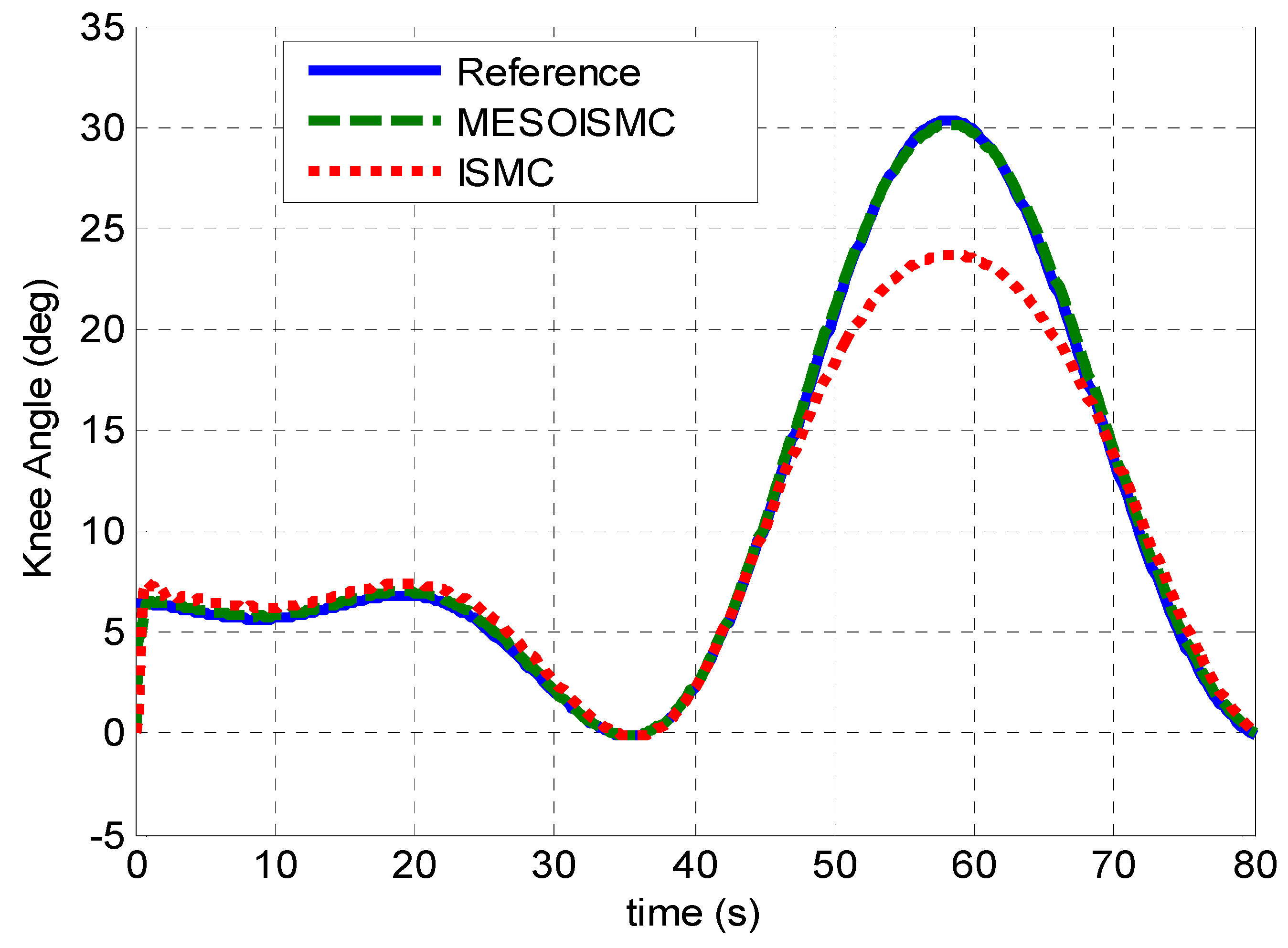
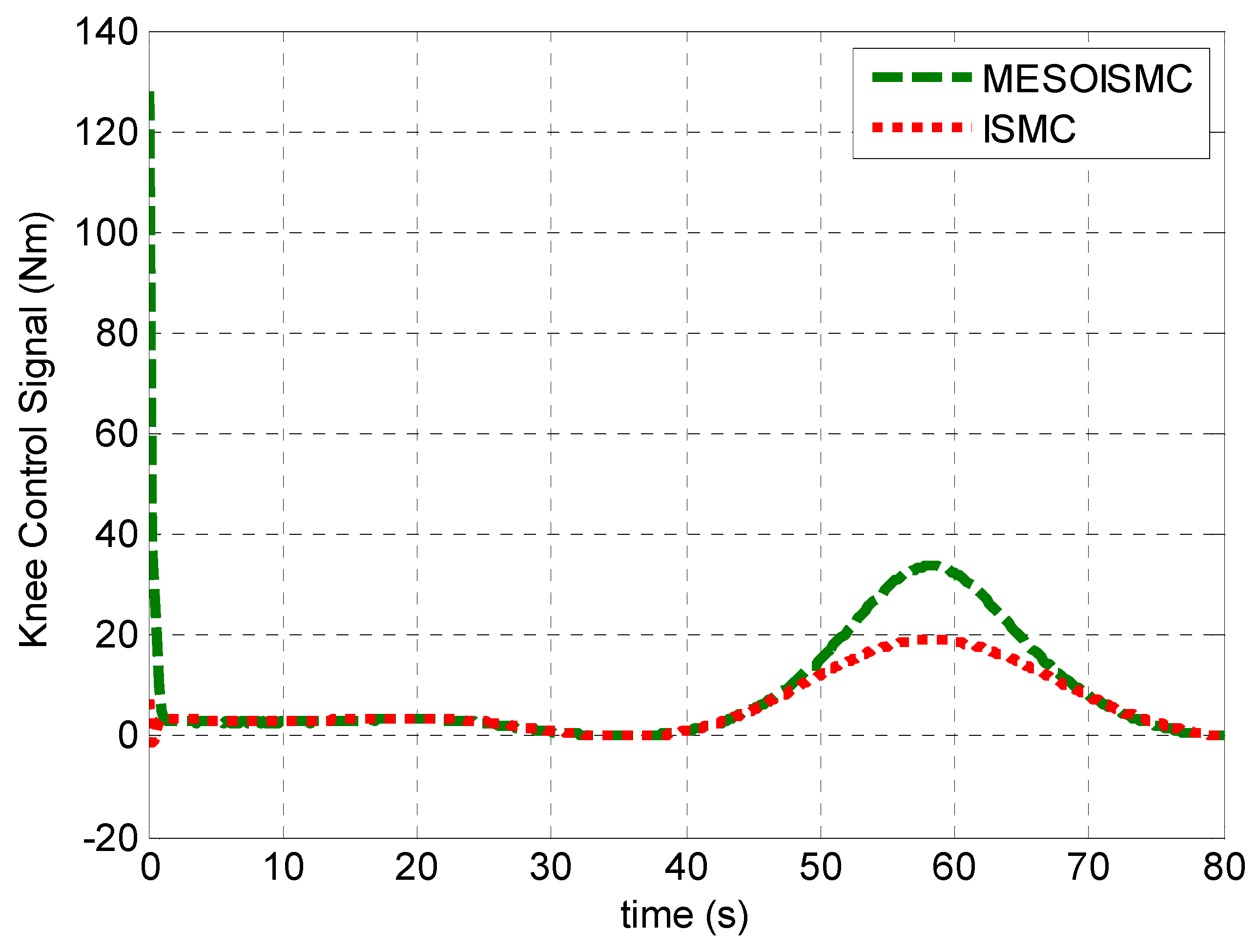
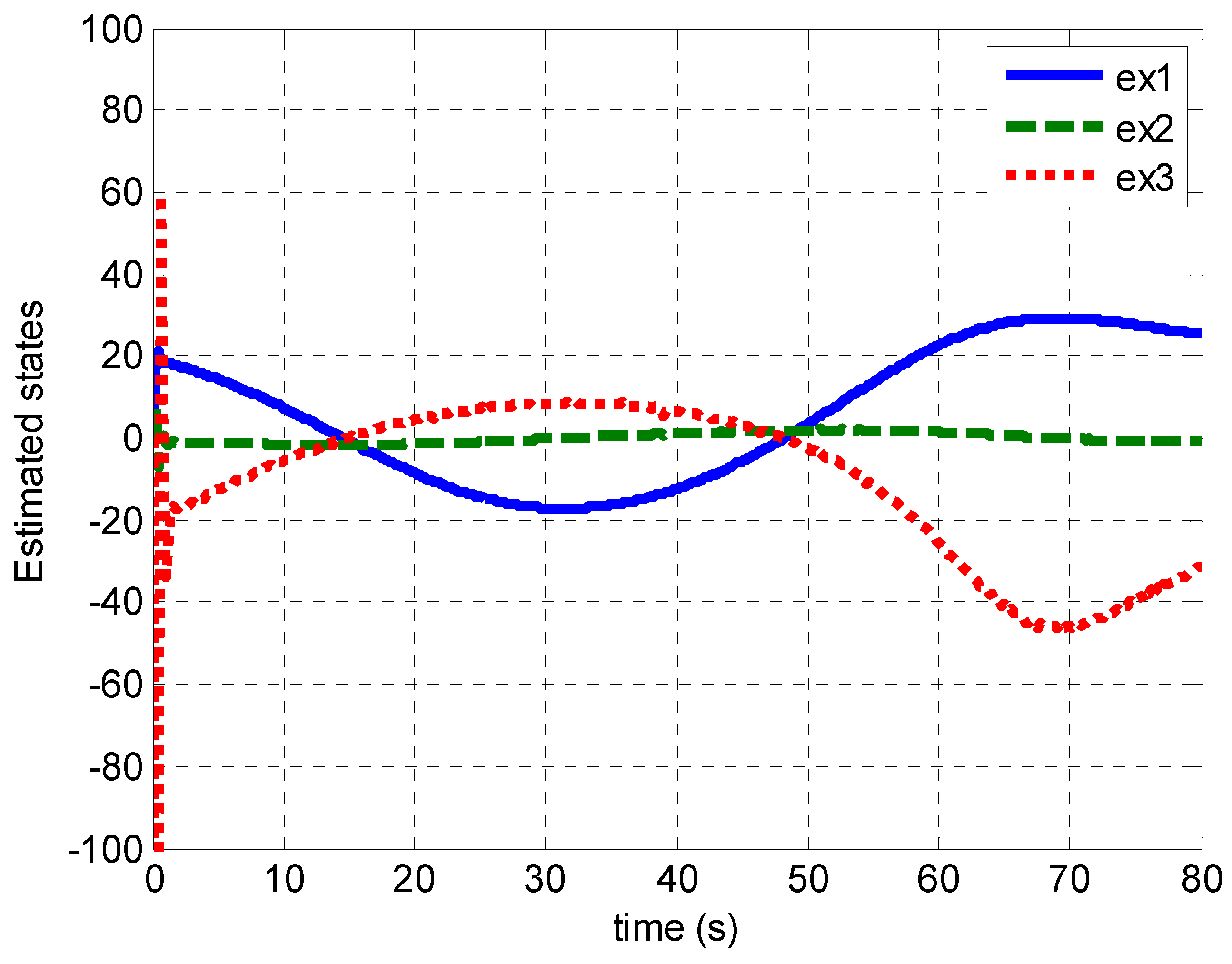
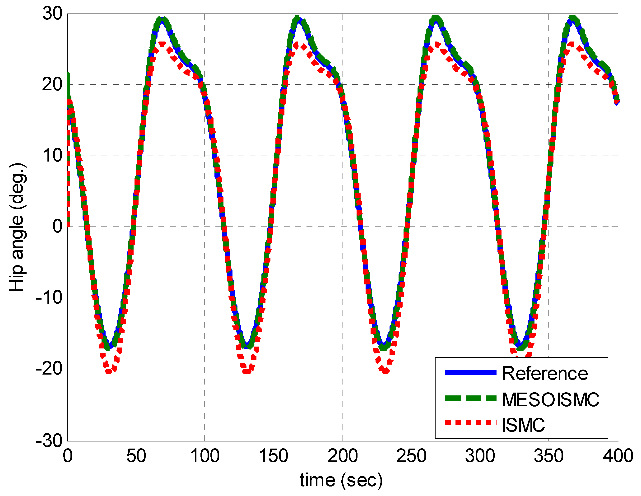
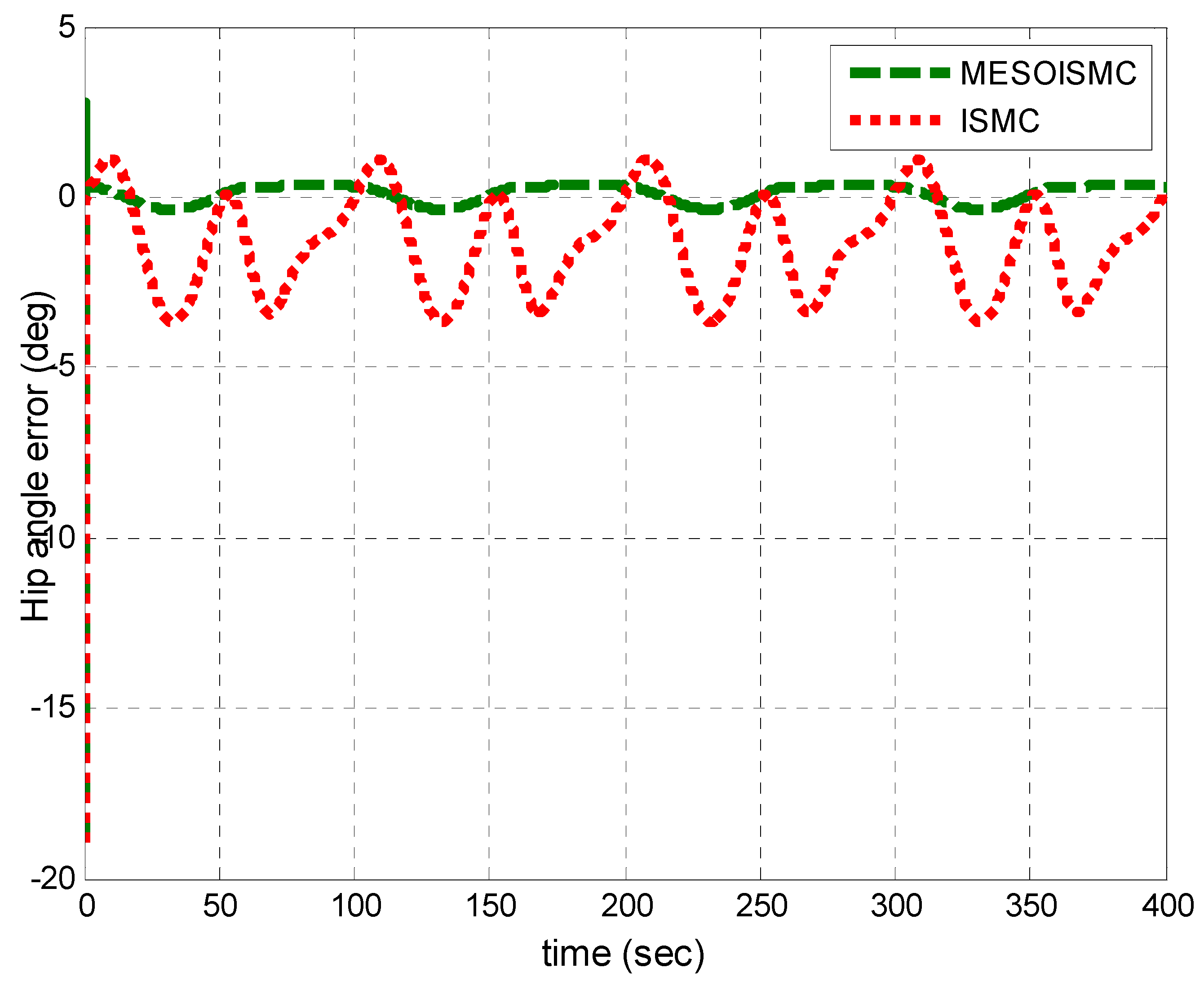
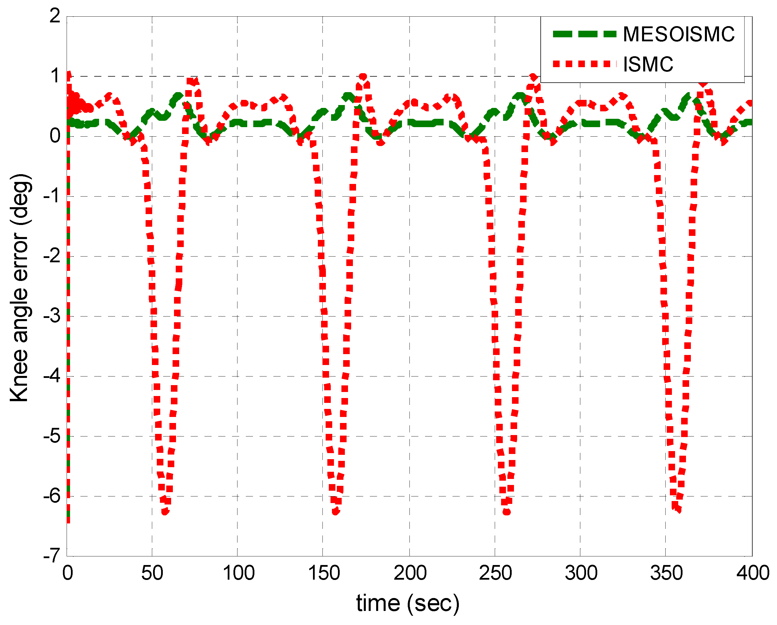
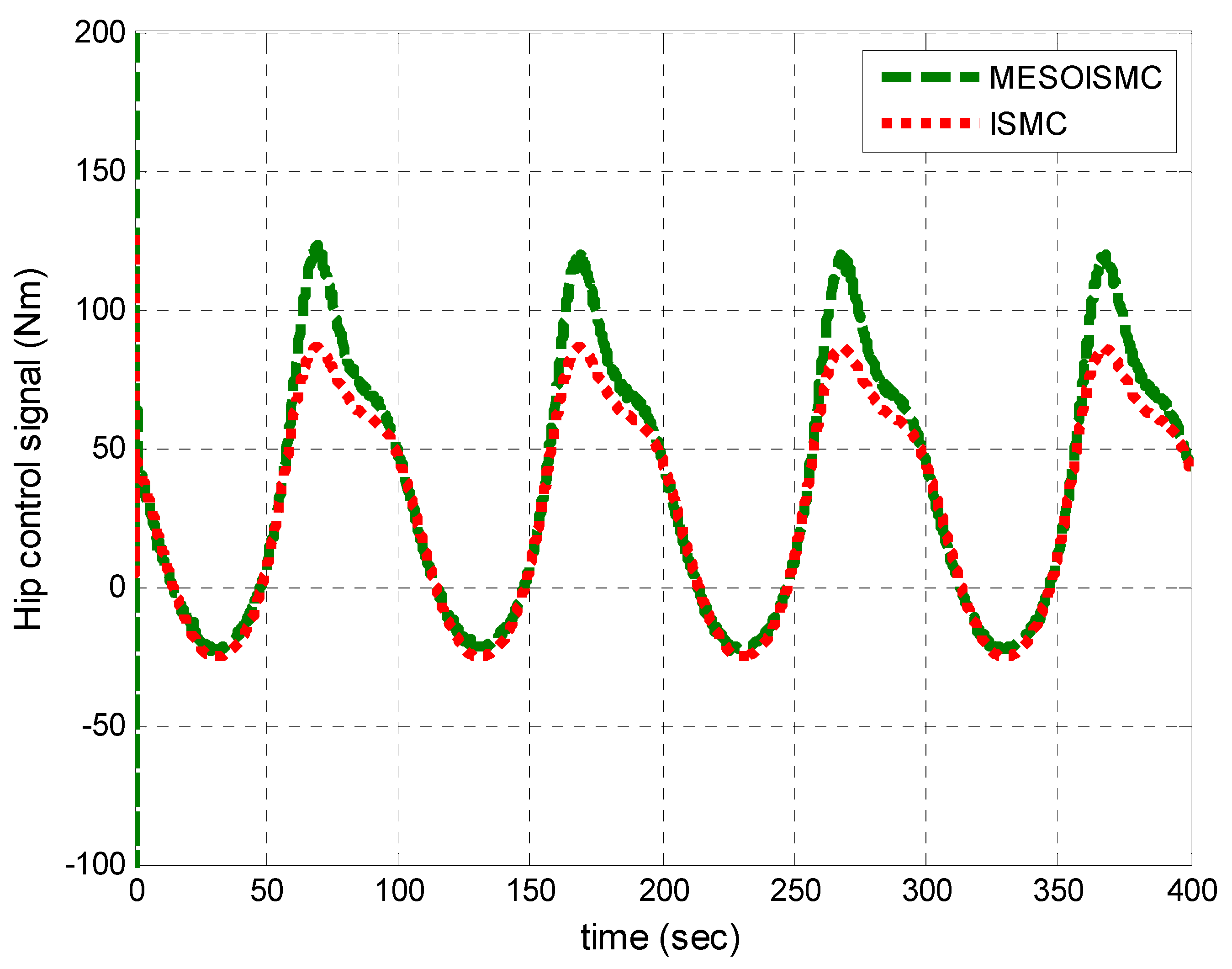
5. Results and Discussions

This section presents the simulation results of both hip and knee joints based on the conventional ISMC and the proposed MESOISMC. Although the control gains were designed based on the linear model, the implementation of these controls was carried out on the nonlinear model of the system. This research mainly aimed to estimate the unknown human torque and reject its effects as a matched disturbance to the system. Figure 4 and Figure 5 show the reference trajectory tracking of the human hip and knee joints, respectively. The figures show that the convergence in the hip and knee tracking of reference trajectory using the proposed MESOISMC was better compared with that obtained with the ISMC. As can be observed in these figures, there was a high error in the tracking performance of ISMC during the change from the stance phase to the swing phase. About 4° error was observed during the phase changes in Figure 4 for the hip angle and about 7° error in the knee angle, as seen from Figure 5. These findings can be observed from Figure 6 and Figure 7, which show the tracking error signals of the two controllers for hip and knee, respectively. Initially, the angle errors were high for MESOISMC and ISMC, which were 20° and 19° for the hip angle and 6.5° and 7.5° for the knee angle, as shown in Figure 6 and Figure 7. This finding was observed because, at the beginning, the human body caused some delay in response due to inertia. Thus, with MESOISMC, the human body followed the exoskeleton motion with approximately zero error. The results indicate that the effects of human torque have been successfully estimated and cancelled. Therefore, the total input torque is completely that of exoskeleton. On this basis, the proposed control generated a control signal that rejected the effect of the estimated human torque and maintained the tracking of the desired trajectory of the patient-intended mobility without safety risk or user discomfort.
Equation (56) was used to calculate the MAE values from the reference trajectory and MESOISMC and ISMC data to measure the performance of the proposed control. Figure 8 shows that the MAE values of the proposed method MESOISMCE and ISMC for hip-angle trajectory tracking were 0.2909° and 1.9419°, respectively. These results indicated an 85.02% improvement in the reference trajectory tracking by the proposed method compared with ISMC. The high tracking error with ISMC can cause user discomfort, and user safety may not be guaranteed during gait training. The error found in ISMC means a delay in human joint motion compared to the reference trajectory. The word “user discomfort” was used to indicate if there was an error or inaccurate position tracking, a user wearing the exoskeleton could experience discomfort at the hip/knee joint. The MAE values for the knee joint angle with MESOISMC and ISMC were 0.1895 and 1.5020, respectively. This finding produced 87.38% error reduction by MESOISMC compared with ISMC. The high tracking error found in ISMC may cause user discomfort and could injure the wearer due to a high angle difference between the exoskeleton hip/knee joint motor’s movement and human joint’s movement. These results indicate that the proposed method is effective for user comfort and safety gait training. Figure 8 shows the bar chart of the MAE values for both hip and knee joints to clearly see the performance comparison of the two controllers.
Figure 9 and Figure 10 show the disturbance signals, which compare the dynamic formulated human torque in Equation (3) with the estimated unknown human torques of the hip and knee joints, respectively. From Figure 10, the maximum estimated positive human hip torque at starting was 60 Nm. Furthermore, it can be observed that the responses of the estimated unknown human torque are in the same pattern as the dynamic formulated human torque derived from the system dynamic in Equation (3). In addition, Figure 9 and Figure 10 show the stance and swing phase during the gait rehabilitation training. The estimated torques rise during the stance phase, which indicates the intention for motion, moving the legs off the ground, and after 40 s, the torques start to drop during the swing phase to show that the patient’s leg is being put back on the ground. This shows that the estimation target has been achieved, and, in addition, the proposed control method which estimated the unknown human torque provided better tracking performance as compared to ISMC, which used the dynamic formulated human torque. Figure 11 and Figure 12 show the input torque, which moved the human exoskeleton after rejection of the human estimated torques for hip and knee, respectively. The ESO had successfully estimated the two system states, x ^ 1 t ,   x ^ 2 t , and the human torque disturbance x ^ 3 t , shown in Figure 13. The estimation of these states helped in reducing the error between the reference trajectory and the output angular position of the hip and knee joints.
Figure 14 and Figure 15 show the effects of using too small or too high values of the gain in the modified signal. It was observed that, when the value is too small, the system response is slow, and this causes a steady state error in the tracking performance, and when the value is too high, it leads to vibration or oscillation, causing instability in the system performance.
Figure 16, Figure 17, Figure 18, Figure 19, Figure 20, Figure 21, Figure 22, Figure 23, Figure 24 and Figure 25 show the replication of Figure 4, Figure 5, Figure 6, Figure 7, Figure 8, Figure 9, Figure 10, Figure 11, Figure 12 and Figure 13 with multiple cycles. It was observed from Figure 20 that the MAE for the MESOISMC and ISMC has values of 0.2875, 1.8689 and 0.1834, 1.4676 for the hip and knee positions, respectively. Similar percentage improvement was observed from the MAE values of the multiple cycles results. A total of 84.62% and 87.50% improvements were found in MESOISMC as compared to ISMC.

6. Conclusion and Future Work

This work proposed and implemented a modified extended state observer based integral sliding mode controller. The control gains were designed based on the linear model; however, the implementation was conducted on the nonlinear model of the system. The proposed control was successfully used for estimation of an unknown human torque and rejection of its effects. The performance of the proposed controller as compared with the ISMC in terms of faster convergence of the hip and knee joint to the reference angle was observed from the MAE values. The MAE values of the proposed method MESOISMCE and ISMC for hip-angle trajectory tracking were 0.2909° and 1.9419°, respectively. These results indicated an 85.02% improvement in the reference trajectory tracking by the proposed method compared with ISMC. The 85.02% improvement in ISMC can cause user discomfort, and user safety may not be guaranteed during gait training. Similarly, MAE values for the knee joint angle with MESOISMC and ISMC were 0.1895 and 1.5020, respectively. This finding produced 87.38% error reduction by MESOISMC compared with ISMC. The high tracking error found in ISMC may cause user discomfort and safety risk to the user. The results indicated that the proposed method is effective and efficient for user comfort and safety during gait rehabilitation training because of its minimum tracking position error. In addition, the system states were estimated, and the error found in MESOISMC was almost zero. Thus, the proposed method had a more effective convergence compared with the ISMC. However, the proposed control is limited to torque estimation and position tracking control to support patients with serious spinal cord injury or stroke. However, this control device can be applied to other neurological disorders involving motor-weakness-related symptoms. The ongoing effort is to implement this proposed control algorithm on our developed prototypes of lower-extremity exoskeletons, such as the wheelchair-exoskeleton hybrid robot [51].

Author Contributions

Conceptualization, A.M.A. and R.C.; methodology, A.M.A. and R.C. software, A.M.A. and R.C., validation, A.M.A.; formal analysis, A.M.A. and R.C.; investigation, A.M.A. and R.C.; resources, R.C.; simulation data collection, A.M.A.; writing—original draft preparation, A.M.A. and R.C.; writing—review and editing, R.C.; visualization, A.M.A. and R.C.; supervision, R.C.; project administration, R.C.; funding acquisition, R.C. All authors have read and agreed to the published version of the manuscript.

Funding

This research project was partly funded by the Thailand Science Research and Innovation Fund, Chulalongkorn University (IND66210017) and by the Intelligent Control Automation of Process Systems Research Unit, Rachadapisek Sompote Fund, Chulalongkorn University.

Data Availability Statement

The data presented in this study are available on request from the corresponding author. The data are not publicly available due to privacy.

Acknowledgments

This research project was supported by the Second Century Fund (C2F), Chulalongkorn University.

Conflicts of Interest

The authors declare no conflict of interest.

Appendix A

The MATLAB Simulink diagram of the proposed controller is given in Figure A1.
Figure A1. MATLAB Simulink diagram of the proposed controller.
Jsan 12 00053 g0a1

References

  1. Baud, R.; Manzoori, A.R.; Ijspeert, A.; Bouri, M. Review of control strategies for lower-limb exoskeletons to assist gait. J. Neuroeng. Rehabil. 2021, 18, 119. [Google Scholar] [CrossRef] [PubMed]
  2. Tiboni, M.; Borboni, A.; Vérité, F.; Bregoli, C.; Amici, C. Sensors and Actuation Technologies in Exoskeletons: A Review. Sensors 2022, 22, 884. [Google Scholar] [CrossRef] [PubMed]
  3. Campagnini, S.; Liuzzi, P.; Mannini, A.; Riener, R.; Carrozza, M.C. Effects of control strategies on gait in robot-assisted post-stroke lower limb rehabilitation: A systematic review. J. Neuroeng. Rehabil. 2022, 19, 52. [Google Scholar] [CrossRef]
  4. Shi, D.; Zhang, W.; Zhang, W.; Ding, X. A Review on Lower Limb Rehabilitation Exoskeleton Robots. Chin. J. Mech. Eng. 2019, 32, 74. [Google Scholar] [CrossRef] [Green Version]
  5. Deng, J.; Wang, P.; Li, M.; Guo, W.; Zha, F.; Wang, X. Structure design of active power-assist lower limb exoskeleton APAL robot. Adv. Mech. Eng. 2017, 9, 9. [Google Scholar] [CrossRef]
  6. Aftabi, H.; Nasiri, R.; Ahmadabadi, M.N. Simulation-based biomechanical assessment of unpowered exoskeletons for running. Sci. Rep. 2021, 11, 11846. [Google Scholar] [CrossRef]
  7. Chaichaowarat, R.; Macha, V.; Wannasuphoprasit, W. Passive Knee Exoskeleton Using Brake Torque to Assist Stair Ascent. In Proceedings of the 2020 IEEE Region 10 Conference (TENCON), Osaka, Japan, 16–19 November 2020; pp. 1165–1170. [Google Scholar] [CrossRef]
  8. Chaichaowarat, R.; Kinugawa, J.; Kosuge, K. Cycling-enhanced Knee Exoskeleton Using Planar Spiral Spring. In Proceedings of the 2018 40th Annual International Conference of the IEEE Engineering in Medicine and Biology Society (EMBC), Honolulu, HI, USA, 18–21 July 2018; Volume 2018, pp. 1–6. [Google Scholar] [CrossRef]
  9. Ullah, Z.; Chaichaowarat, R.; Wannasuphoprasit, W. Variable Damping Actuator Using an Electromagnetic Brake for Impedance Modulation in Physical Human–Robot Interaction. Robotics 2023, 12, 80. [Google Scholar] [CrossRef]
  10. Gupta, A.; Al-Anbuky, A.; McNair, P. Activity Classification Feasibility Using Wearables: Considerations for Hip Fracture. J. Sens. Actuator Netw. 2018, 7, 54. [Google Scholar] [CrossRef] [Green Version]
  11. Prabhakar, A.J.; Prabhu, S.; Agrawal, A.; Banerjee, S.; Joshua, A.M.; Kamat, Y.D.; Nath, G.; Sengupta, S. Use of Machine Learning for Early Detection of Knee Osteoarthritis and Quantifying Effectiveness of Treatment Using Force Platform. J. Sens. Actuator Netw. 2022, 11, 48. [Google Scholar] [CrossRef]
  12. Pornpipatsakul, K.; Ajavakom, N. Estimation of Knee Assistive Moment in a Gait Cycle Using Knee Angle and Knee Angular Velocity through Machine Learning and Artificial Stiffness Control Strategy (MLASCS). Robotics 2023, 12, 44. [Google Scholar] [CrossRef]
  13. Gonçalves, R.S.; Rodrigues, L.A.O.; Humbert, R.; Carbone, G. A User-Friendly Nonmotorized Device for Ankle Rehabilitation. Robotics 2023, 12, 32. [Google Scholar] [CrossRef]
  14. Cheng, C.-A.; Huang, T.-H.; Huang, H.-P. Bayesian human intention estimator for exoskeleton system. In Proceedings of the 2013 IEEE/ASME Inter-national Conference on Advanced Intelligent Mechatronics, Wollongong, NSW, Australia, 9–12 July 2013; pp. 465–470. [Google Scholar] [CrossRef]
  15. Ullauri, J.B.; Peternel, L.; Ugurlu, B.; Yamada, Y.; Morimoto, J. On the EMG-based torque estimation for humans coupled with a force-controlled elbow exoskeleton. In Proceedings of the 2015 International Conference on Advanced Robotics (ICAR), 2015 International Conference on Advanced Robotics (ICAR), Istanbul, Turkey, 27–31 July 2015; pp. 302–307. [Google Scholar] [CrossRef]
  16. Gui, K.; Liu, H.; Zhang, D. A Practical and Adaptive Method to Achieve EMG-Based Torque Estimation for a Robotic Exoskeleton. IEEE/ASME Trans. Mechatron. 2019, 24, 483–494. [Google Scholar] [CrossRef]
  17. Nsugbe, E.; Al-Timemy, A.H. Shoulder girdle recognition using electrophysiological and low frequency anatomical contraction signals for prosthesis control. CAAI Trans. Intell. Technol. 2021, 7, 81–94. [Google Scholar] [CrossRef]
  18. Gopura, R.A.; Kiguchi, R.C.; Lalitharatne, K.; Zhang, T.D. EMG/EEG Signals-based Control of Assistive and Rehabilitation Robots. Front. Res. Top. 2022, 14, 840321. [Google Scholar] [CrossRef]
  19. Ferreira, A.; Celeste, W.C.; Cheein, F.A.; Bastos-Filho, T.F.; Sarcinelli-Filho, M.; Carelli, R. Human-machine interfaces based on EMG and EEG applied to robotic systems. J. Neuroeng. Rehabil. 2008, 5, 10. [Google Scholar] [CrossRef] [PubMed] [Green Version]
  20. Li, X.; Liu, S.; Chang, Y.; Li, S.; Fan, Y.; Yu, H. A Human Joint Torque Estimation Method for Elbow Exoskeleton Control. Int. J. Humanoid Robot. 2020, 17, 1950039. [Google Scholar] [CrossRef]
  21. Fattah, A.; Agrawal, S.K.; Catlin, G.; Hamnett, J. Design of a Passive Gravity-Balanced Assistive Device for Sit-to-Stand Tasks. J. Mech. Des. 2005, 128, 1122–1129. [Google Scholar] [CrossRef]
  22. Fang, Q.; Li, G.; Xu, T.; Zhao, J.; Cai, H.; Zhu, Y. A Simplified Inverse Dynamics Modelling Method for a Novel Rehabilitation Exoskeleton with Parallel Joints and Its Application to Trajectory Tracking. Math. Probl. Eng. 2019, 2019, 4602035. [Google Scholar] [CrossRef]
  23. Arijit, A.; Pratihar, D.K. Inverse dynamics learned gait planning of an exoskeleton to negotiate uneven terrains using neural networks. Int. J. Hybrid Intell. Syst. 2016, 13, 49–62. [Google Scholar] [CrossRef]
  24. Cao, H.; Yin, Y.; Du, D.; Lin, L.; Gu, W.; Yang, Z. Neural-Network Inverse Dynamic Online Learning Control on Physical Exoskeleton. In Neural Information Processing, Processings of the 13th International Conference, ICONIP 2006, Hong Kong, China, 3–6 October 2006; Springer: Berlin/Heidelberg, Germany; Volume 4234, pp. 702–710. [CrossRef]
  25. Chen, W.-H.; Ballance, D.; Gawthrop, P.; O’Reilly, J. A nonlinear disturbance observer for robotic manipulators. IEEE Trans. Ind. Electron. 2000, 47, 932–938. [Google Scholar] [CrossRef] [Green Version]
  26. Chaichaowarat, R.; Nishimura, S.; Krebs, H.I. Macro-Mini Linear Actuator Using Electrorheological-Fluid Brake for Impedance Modulation in Physical Human–Robot Interaction. IEEE Robot. Autom. Lett. 2022, 7, 2945–2952. [Google Scholar] [CrossRef]
  27. Chaichaowarat, R.; Nishimura, S.; Krebs, H.I. Design and Modeling of a Variable-Stiffness Spring Mechanism for Impedance Modulation in Physical Human–Robot Interaction. Proc. IEEE Int. Conf. Robot. Autom. 2021, 2021, 7052–7057. [Google Scholar] [CrossRef]
  28. Chaichaowarat, R.; Nishimura, S.; Nozaki, T.; Krebs, H.I. Work in the Time of COVID-19: Actuators and Sensors for Rehabilitation Robotics. IEEJ J. Ind. Appl. 2022, 11, 256–265. [Google Scholar] [CrossRef]
  29. Nishimura, S.; Chaichaowarat, R.; Krebs, H.I. Human-Robot Interaction: Controller Design and Stability. In Proceedings of the 2020 8th IEEE RAS/EMBS International Conference for Biomedical Robotics and Biomechatronics (BioRob), New York, NY, USA, 29 November–1 December 2020. [Google Scholar] [CrossRef]
  30. Fang, B.; Zhou, Q.; Sun, F.; Shan, J.; Wang, M.; Xiang, C.; Zhang, Q. Gait Neural Network for Human-Exoskeleton Interaction. Front. Neurorobotics 2020, 14, 58. [Google Scholar] [CrossRef]
  31. Jung, J.-Y.; Heo, W.; Yang, H.; Park, H. A Neural Network-Based Gait Phase Classification Method Using Sensors Equipped on Lower Limb Exoskeleton Robots. Sensors 2015, 15, 27738–27759. [Google Scholar] [CrossRef] [PubMed]
  32. Fuentes-Alvarez, R.; Hernandez, J.H.; Matehuala-Moran, I.; Alfaro-Ponce, M.; Lopez-Gutierrez, R.; Salazar, S.; Lozano, R. Assistive robotic exoskeleton using recurrent neural networks for decision taking for the robust trajectory tracking. Expert Syst. Appl. 2022, 193, 116482. [Google Scholar] [CrossRef]
  33. Yu, J.; Zhang, S.; Wang, A.; Li, W.; Ma, Z.; Yue, X. Humanoid control of lower limb exoskeleton robot based on human gait data with sliding mode neural network. CAAI Trans. Intell. Technol. 2022, 7, 606–616. [Google Scholar] [CrossRef]
  34. Wang, J.; Liu, J.; Zhang, G.; Guo, S. Periodic event-triggered sliding mode control for lower limb exoskeleton based on human–robot cooperation. ISA Trans. 2021, 123, 87–97. [Google Scholar] [CrossRef]
  35. Kommuri, S.K.; Han, S.; Lee, S. External Torque Estimation Using Higher Order Sliding-Mode Observer for Robot Manipulators. IEEE/ASME Trans. Mechatron. 2021, 27, 513–523. [Google Scholar] [CrossRef]
  36. Javadi, A.; Chaichaowarat, R. Position and stiffness control of an antagonistic variable stiffness actuator with input delay using super-twisting sliding mode control. Nonlinear Dyn. 2022, 111, 5359–5381. [Google Scholar] [CrossRef]
  37. Han, S.; Wang, H.; Tian, Y. A linear discrete-time extended state observer-based intelligent PD controller for a 12 DOFs lower limb exoskeleton LLE-RePA. Mech. Syst. Signal Process. 2019, 138, 106547. [Google Scholar] [CrossRef]
  38. Zhao, J.; Yang, T.; Sun, X.; Dong, J.; Wang, Z.; Yang, C. Sliding mode control combined with extended state observer for an ankle exoskeleton driven by electrical motor. Mechatronics 2021, 76, 102554. [Google Scholar] [CrossRef]
  39. Long, Y.; Peng, Y. Extended State Observer-Based Nonlinear Terminal Sliding Mode Control with Feedforward Compensation for Lower Extremity Exoskeleton. IEEE Access 2022, 10, 8643–8652. [Google Scholar] [CrossRef]
  40. Han, Y.; Zhu, S.; Zhou, Y.; Gao, H. An admittance controller based on assistive torque estimation for a rehabilitation leg exoskeleton. Intell. Serv. Robot. 2019, 12, 381–391. [Google Scholar] [CrossRef]
  41. Liang, C.; Hsiao, T. Admittance Control of Powered Exoskeletons Based on Joint Torque Estimation. IEEE Access 2020, 8, 94404–94414. [Google Scholar] [CrossRef]
  42. Porras, D.C.; Jacobs, J.V.; Inzelberg, R.; Bahat, Y.; Zeilig, G.; Plotnik, M. Patterns of whole-body muscle activations following vertical perturbations during standing and walking. J. Neuroeng. Rehabil. 2021, 18, 75. [Google Scholar] [CrossRef]
  43. Akbas, T.; Kim, K.; Doyle, K.; Manella, K.; Lee, R.; Spicer, P.; Knikou, M.; Sulzer, J. Rectus femoris hyperreflexia contributes to Stiff-Knee gait after stroke. J. Neuroeng. Rehabil. 2020, 17, 117. [Google Scholar] [CrossRef]
  44. Labruyère, R. Robot-assisted gait training: More randomized controlled trials are needed! Or maybe not? J. Neuroeng. Rehabil. 2022, 19, 58. [Google Scholar] [CrossRef]
  45. Castanos, F.; Fridman, L. Analysis and design of integral sliding manifolds for systems with unmatched perturbations. IEEE Trans. Autom. Control 2006, 51, 853–858. [Google Scholar] [CrossRef] [Green Version]
  46. Feng, C.C. Integral Sliding-Based Robust Control, Recent Advances in Robust Control: Novel Approaches and Design Methods; Muller, A., Ed.; Intechopen: London, UK, 2011. [Google Scholar]
  47. Changcheng, C.; Li, Y.-R.; Chen, C.-T. Assistive Mobility Control of a Robotic Hip-Knee Exoskeleton for Gait Training. Sensors 2022, 22, 5045. [Google Scholar] [CrossRef]
  48. Abdullahi, A.; Mohamed, Z.; Selamat, H.; Pota, H.; Abidin, M.Z.; Fasih, S. Efficient control of a 3D overhead crane with simultaneous payload hoisting and wind disturbance: Design, simulation and experiment. Mech. Syst. Signal Process. 2020, 145, 106893. [Google Scholar] [CrossRef]
  49. Tanyildizi, A.K.; Yakut, O.; Tasar, B. Mathematical modeling and control of lower extremity exoskeleton. Biomed. Res. 2018, 29, 1947–1952. [Google Scholar] [CrossRef] [Green Version]
  50. Zhang, Y.; Wang, J.; Li, W.; Wang, J.; Yang, P. A model-free control method for estimating the joint angles of the knee exoskeleton. Adv. Mech. Eng. 2018, 10, 1–10. [Google Scholar] [CrossRef] [Green Version]
  51. Chaichaowarat, R.; Prakthong, S.; Thitipankul, S. Transformable Wheelchair–Exoskeleton Hybrid Robot for Assisting Human Locomotion. Robotics 2023, 12, 16. [Google Scholar] [CrossRef]
Figure 1. Conceptual design of the hip–knee human–exoskeleton system. The directions of the hip torque and knee torque are shown. The angles of rotations and direction of the rotations at the hip and knee were also shown. The τ h t and τ k t were the human-contributed hip and knee torques. These two joints’ torques are unknown and, therefore, can be estimated by the observer. M 1 ,   l 1   and   M 2 ,   l 2   are the masses and lengths of the links connecting hip to knee and knee to ankle.
Jsan 12 00053 g001
Figure 2. Conceptual ISMC block diagram showing the equivalent and switching control. In addition, the nominal and actual system are also shown. r ,   x ,   u t , are the reference hip/knee position input, the measured hip/knee position and the total control signal of the exoskeleton motors, respectively. The equivalent control which is designed to achieve desire positioning of the hip/knee is u e q = K x t + N r t , ϕ t is the human torque which was considered as disturbance in this work, and u s w = Γ t tan h s t is the switching control signal that addresses the disturbance rejections.
Jsan 12 00053 g002
Figure 3. Conceptual MESOISMC block diagram showing the Modified ISMC with ESO. The modification terms are β e ^ . This figure is the modification of Figure 2 which shows the cascade combination of the MESOISMC where r ,   x ,   u t   are the reference hip/knee position input, the measured hip/knee position, and the total control signal of the exoskeleton motors, respectively. The equivalent control which is designed to achieve desired positioning of the hip/knee is u e q = K x t + N r t , ϕ t is the human torque, which was considered as disturbance in this work, and u s w = Γ t tanh s t is the switching control signal that addresses the disturbance rejections.
Jsan 12 00053 g003
Figure 4. Hip angle tracking. From the figure legend, the reference signal is the desire hip angle, MESOISMC is the tracking angle that resulted from the controlled effort of MESOISMC, and ISMC is the tracking angle achieved from the control effort of ISMC. From this figure, it can be observed that the MESOISMC has better tracking as compared to ISMC. It was observed in the ISMC response that there is a high position tracking error in this figure from 20 s to about 45 s, and later, from 60 s to 80 s. These would cause user discomfort or may injure the user.
Jsan 12 00053 g004
Figure 5. Knee angle tracking. Similarly, in this figure, the reference signal is the desire knee angle, MESOISMC is the tracking angle that resulted from the controlled effort of MESOISMC, and ISMC is the tracking angle achieved from the control effort of ISMC. From the tracking performance, it can be observed that the MESOISMC has better tracking as compared to ISMC. It was observed in this figure there is a high tracking error from 48 s to almost 70 s. This means the user’s knee was not properly tracking the exoskeleton knee motor movement.
Jsan 12 00053 g005
Figure 6. Hip angle tracking error. From this figure, the reader can clearly observe the tracking performance based on the controller with high tracking error. It is seen that the ISMC has the higher tracking error as compared to MESOISMC, which has an error close to zero. This validated the claim made in Figure 4 above.
Jsan 12 00053 g006
Figure 7. Knee angle tracking error. The tracking performance based on the controller with a high tracking error can clearly be seen from this figure. The ISMC has the higher tracking error as compared to MESOISMC. This validated the claim made in Figure 5 above.
Jsan 12 00053 g007
Figure 8. Hip and knee MAE values. This figure further illustrated the difference in the tracking performance based on the Mean Absolute Error of the MESOISMC and ISMC. The controller with lowest MAE has the high tracking performance.
Jsan 12 00053 g008
Figure 9. Estimated human hip torque. This figure shows the estimated human hip torques with MESOISMC and the formulated ISMC. The estimated torque using MESOISMC shows more accurate results based on the generated high torque at the beginning, which is true for intended motion.
Jsan 12 00053 g009
Figure 10. Estimated human knee torque. The estimated human knee torques is shown in this figure. The estimated torque using MESOISMC shows more accurate results based on the generated high torque at the beginning, which is true for intended motion; a high torque is generated to start walking, which gradually reduces as the motion changes from the stand phase to the swing phase.
Jsan 12 00053 g010
Figure 11. Hip input torque. The control signal is shown in this figure. It is observed that the MESOISMC has a high control signal. This was because of the modified term which helped create rapid convergence performance.
Jsan 12 00053 g011
Figure 12. Knee input torque. A similar case was observed in this figure, where the MESOISMC has high control signal as a result of the added term that modifies the controller effort in achieving rapid convergence performance.
Jsan 12 00053 g012
Figure 13. Estimated hip states x ^ 1 t , x ^ 2 t ,   x ^ 3 t . The estimated states are shown in this figure, and the three estimated parameters are the estimated hip angle position, hip angle velocity, and human hip torque. It can be observed that the estimated hip angle is similar to the desire hip angle shown in Figure 4.
Jsan 12 00053 g013
Figure 14. Effects of different values of β h on the system performance. It can be observed from this figure that, with a small value of β h , there exists a steady state error, and when the value is high, it causes vibration/oscillation leading to unstable performance.
Jsan 12 00053 g014
Figure 15. Effects of different values of β k on the system performance. It can be observed from this figure that, with a small value of β k , there exists a steady state error, and when the value is high, it causes vibration/oscillation leading to unstable performance.
Jsan 12 00053 g015
Figure 16. Hip angle response for multiple cycles.
Jsan 12 00053 g016
Figure 17. Hip angle tracking error for multiple cycles.
Jsan 12 00053 g017
Figure 18. Knee angle response for multiple cycles.
Jsan 12 00053 g018
Figure 19. Knee angle tracking error for multiple cycles.
Jsan 12 00053 g019
Figure 20. Hip and knee MAE values from multiple cycles.
Jsan 12 00053 g020
Figure 21. Estimated human hip torque for multiple cycles.
Jsan 12 00053 g021
Figure 22. Estimated human knee torque for multiple cycles.
Jsan 12 00053 g022
Figure 23. Hip control signal for multiple cycles.
Jsan 12 00053 g023
Figure 24. Knee control signal for multiple cycles.
Jsan 12 00053 g024
Figure 25. Estimated states for multiple cycles.
Jsan 12 00053 g025
Table 1. System parameters as presented in [49].
ParameterSymbolMagnitudeUnits
Human Thigh lengthl10.45m
Human Shank length l20.43m
Exo-Thigh length l30.45m
Exo-Shank length l40.43m
Human Thigh Mass m18kg
Human Shank mass m24kg
Exo-Thigh mass m31kg
Exo-Shank mass m41kg
Gravitational acceleration g9.81m/s2
Frequency f0.16Hz
Scaling Factor for Hip β h 80none
Scaling Factor for Knee β k 18none
Note l1 = l3, l2 = l4, M1 = m1 + m3, M2 = m2 + m4.
Table 2. Reference hip-knee trajectory parameters.
ParametersHip ReferenceKnee Reference
θ 0 9.0929.092
a 1 −20.86−3.99
b 1 6.744−7.14
a 2 5.0218.030
b 2 2.1014.110
a 3 −0.1416−4.141
b 3 1.1970.200
a 4 −0.12990.013
b 4 −0.21580.220
w n 0.063140.06314
Disclaimer/Publisher’s Note: The statements, opinions and data contained in all publications are solely those of the individual author(s) and contributor(s) and not of MDPI and/or the editor(s). MDPI and/or the editor(s) disclaim responsibility for any injury to people or property resulting from any ideas, methods, instructions or products referred to in the content.

