
Performance Assessment and Mitigation of Timing Covert Channels over the IEEE 802.15.4


1
PORTIC, Polytechnic Institute of Porto, Rua Arquitecto Lobão Vital, 172, 4200-375 Porto, Portugal
2
ISEP-IPP, Instituto Superior de Engenharia do Porto, Rua Dr. António Bernardino de Almeida, 431, 4249-015 Porto, Portugal
3
INESC-TEC, Rua Dr. Roberto Frias, 4200-465 Porto, Portugal
*
Author to whom correspondence should be addressed.
J. Sens. Actuator Netw. 2023, 12(4), 60; https://doi.org/10.3390/jsan12040060
Submission received: 12 June 2023
/
Revised: 11 July 2023
/
Accepted: 18 July 2023
/
Published: 1 August 2023
Abstract
:The fast development and adoption of IoT technologies has been enabling their application into increasingly sensitive domains, such as Medical and Industrial IoT, in which safety and cyber-security are paramount. While the number of deployed IoT devices increases annually, they still present severe cyber-security vulnerabilities, becoming potential targets and entry points for further attacks. As these nodes become compromised, attackers aim to set up stealthy communication behaviours, to exfiltrate data or to orchestrate nodes in a cloaked fashion, and network timing covert channels are increasingly being used with such malicious intents. The IEEE 802.15.4 is one of the most pervasive protocols in IoT and a fundamental part of many communication infrastructures. Despite this fact, the possibility of setting up such covert communication techniques on this medium has received very little attention. We aim to analyse the performance and feasibility of such covert-channel implementations upon the IEEE 802.15.4 protocol, particularly upon the DSME behaviour, one of the most promising for large-scale time critical communications. This enables us to better understand the involved risk of such threats and help support the development of active cyber-security mechanisms to mitigate these threats, which, for now, we provide in the form of practical network setup recommendations.
1. Introduction
The advancements in information and communication technology in the past decades have been converging into a new communication paradigm, in which everything is expected to be interconnected with the heightened pervasiveness and ubiquity of the Internet of Things (IoT) paradigm. The IoT, a collection of semi-autonomous, internet-connected devices comprised of computing, networking, sensing and actuation capabilities interconnected with the physical world [1], encompasses a myriad of several different technologies, such as Wireless Sensor Networks, Radio-Frequency Identification and Machine-to-Machine communications. Now, much more than a buzzword, the IoT is becoming a pervasive reality, enabling applications in multiple domains such as medical care [2], agriculture [3], supply chains [4], transportation [5] and smart cities [6].
As these technologies mature, they are increasingly finding their way into the industrial domain, to support what is now dubbed as Industry 4.0: the convergence of IoT, Cyber Physical Systems (CPS) and Cloud technologies on the factory floor, enabling new data insights, highly customised products and technological autonomy. Along these lines, the number of deployed IoT devices continues to increase annually and is estimated to reach 75 billion by 2025 [7]; the amount of interconnected devices per network will exponentially increase as well. However, IoT verticals present a severe set of challenges, enhanced by the IoT scale, heterogeneity and fast adoption. In addition, this trend, despite opening exciting opportunities, also unlocks a variety of new security threats [8,9,10], with heightened security and privacy risks, particularly in industrial and medical scenarios [11].
Unfortunately, most of these internet-connected IoT devices do not have the same experience-induced resilience to intrusion, hacking and sabotage attacks that other computing devices have acquired [12]. On the contrary, they show a significant level of vulnerability. With 70% of IoT devices found to have serious security vulnerabilities, such as unencrypted network services and weak password requirements, and 90% of them collecting personal information [13], there is a critical need for improving IoT security approaches. The need is further exacerbated as bad actors exploit these weaknesses to conduct attacks against IoT infrastructure [14,15,16], even taking down large swaths of the internet by leveraging Distributed Denial of Service (D-DoS) attacks such as the Mirai botnet [17,18], which relied upon illegitimate usage of 400,000 IoT devices.
Generally, IoT threats stem both from the intrinsic enhanced vulnerability of a system that is newly connected to other legacy systems connected to Internet gateways and from the incredible number of intrusion targets introduced by the IoT paradigm (e.g., home connected appliances, wearables, connected vehicles, etc.). In the case of Industry 4.0, devices may be exploited for exfiltrating sensitive data with the intent of industrial espionage, to scale up an attack to more critical parts of a factory (or even to a completely different infrastructure) or, simply, and often more dangerous, to sabotage machinery with the intent of physically endangering a factory or voiding its products [12].
The popular solution to these concerns has been the introduction of cryptographic techniques to support data encryption and secure authentication. However, traditional cryptography methods for network security pose important and significant challenges. On the one hand, IoT “things” are often equipped with limited resources in terms of energy consumption, memory capacity and computational power [19]. Such limitations hinder the direct implantation of conventional Internet security techniques, such as AES or TLS, into many IoT solutions [20,21]. Moreover, their absence may lead to various security and privacy attacks, including eavesdropping, network side-channel attacks and tracking. On the other hand, encryption cannot solve all security problems in IoT systems; for instance, if an IoT node establishes covert communication with another device without being detected by an adversary, encryption is insufficient to prevent eavesdropping [22].
In such a concerning scenario, particularly when physical access to the IoT infrastructure is possible, a very important element in any attack is, thus, represented by the capability of the attacker to exploit a covert channel and information-hiding techniques. In fact, whether the goal is exfiltration of critical information or to induce unintended behaviour of a node, there is the need for communicating with the compromised node without disclosing the fact that it has been compromised. Indeed, network covert channels are increasingly being used to support malware with stealthy behaviours (stegomalware), for instance, to exfiltrate data or to orchestrate nodes of a botnet in a cloaked fashion [23]. However, the detection of such attacks is difficult, as it is unknown in advance where the secret information has been hidden, which is worsened by the fact that network covert channels usually feature low data rates. Furthermore, neutralisation or mitigation is not straightforward, as it is hard to not disrupt legitimate flows or degrade the quality of service, particularly at the perception layer of an Industrial IoT (IIoT) application. Consequently, countermeasures are tightly coupled to specific channel architectures, leading to under-generalised, and often scarcely scalable, approaches. Hence, we argue that there is an extreme need for analysing the performance of covert channel attacks regarding reference IIoT protocols.
For all these reasons, we argue that there is an extreme need for (1) analysing the performance of covert channel attacks and (2) proposing novel techniques that can leverage the usage of such techniques in innovative ways, for instance, to devise new information security mechanisms.
Although there are several IoT-enabling communication architectures that can help in achieving energy efficient industrial communication, the communication requirements of these time-critical processes demand improved Quality of Service (QoS) in terms of reliability, timeliness and robustness. These stringent requirements on the communication protocols have been increasingly supported by IEEE 802.15.4 [24], to address the ever-growing demands for low-power, low-range and robust wireless communication.
The Institute of Electrical and Electronics Engineers Standards Association (IEEE-SA) published the IEEE 802.15.4e amendment during the fall of 2012 [25], aiming to enhance and extend the functionalities of the IEEE 802.15.4-2011 protocol. The enhancements consisted of several MAC behaviours, which, in addition to providing deterministic communication, are also designed to support multi-channel frequency hopping mechanisms, such as in the case of the Deterministic and Synchronous Multichannel Extension (DSME) and Time Slotted Channel Hopping (TSCH). There are also other MAC behaviours such as the Low Latency Deterministic Network (LLDN), which uses Time Division Multiple Access (TDMA) to provide timing guarantees. DSME and TSCH were incorporated into the revised version IEEE 802.15.4-2020 [24] and constitute the most interesting options for time-critical communications.
In the particular case of timing covert channels, which rely on timing manipulation rather than steganographic approaches, such implementations can easily leverage the time-critical characteristics of the protocol to convey covert information, making them very hard to detect. This is critical particularly for the DSME, as its non-contention portion of the superframe features critically timed transmission slots and each avails multiple packet transmissions, contrary to the TSCH, which turns it into a great target for such timing manipulations. Unfortunately, there has been no thorough analysis of covert channel implementations over this communication protocol. This fact prevents network designers and security experts from evaluating risks and developing or implementing relevant detection and mitigation strategies.
Therefore, in this work, we aim to analyse the performance and feasibility of such covert channel implementations upon the IEEE 802.15.4 protocol, particularly on the DSME. We intend to support the development of new mechanisms and add-ons that can effectively contribute to improving the current state-of-art of IoT systems which rely on these, or similar, underlying communication technologies. In order to achieve this, we start by providing the cyber-security and IoT communities with a simulation model, featuring several covert channel implementations, that can be easily deployed and analysed. This implementation is then used as a baseline to evaluate the performance of different timing covert-channel techniques in respect to different networking settings. This knowledge will be fundamental in order to devise new mechanisms that leverage these hidden protocol features to implement innovative information security ideas. Afterwards, we propose a set of recommendations that can be implemented in any DSME network simply by tuning a set of network configuration parameters. We believe this work will be fundamental towards a better understanding of these threats and risks over future IIoT deployments, contributing to the improvement of their security. The remainder of the paper is structured as follows. Section 2 provides an overview of the relevant research background. Section 3 describes the main features of the supporting IEEE 802.15.4 communication protocol. Section 4 overviews the architectural design of the covert channels’ implementation and establishes the simulation setup for the following performance analysis. Section 5 presents the performance evaluation results and provides a few insights on how to mitigate the impact of such techniques when deployed. Finally, a discussion of the main conclusions is provided in Section 6.
2. Research Background
In network covert channels, data are hidden over legitimate communications by relying upon the network protocols as carriers. This concept of covert channels, first introduced in [26], postulates that, in general, covert channels can be divided into storage and timing channels. In storage covert channels, processes interact via a shared resource, directly or indirectly, using read and write operations. In the context of network steganography, storage covert channels hide data by storing them in the protocol header and/or in the Protocol Data Unit (PDU). On the other hand, timing channels hide data by manipulating some event timing, such as the packet inter-arrival time, or by changing the packet order.
The first evidence of an exploit of the timing features of network packets was developed in [27] by analysing several vulnerabilities to covert channel techniques in LAN protocols. Since this date, the evolution regarding covert channels has been considerable, and several kinds have been implemented in a plethora of widespread network protocols and applications [28,29,30], including, more recently, particular emphasis on LoRa [31,32]. Importantly (and often surprisingly), such covert communication implementations can also be leveraged with beneficial objectives, as in [33], in which covert channels were used to provide authentication support to automotive CAN bus implementations.
However, just a few works address the quite pervasive IEEE 802.15.4 protocol. At the physical layer, the authors in [34] developed a covert channel by exploiting the Direct Spread Spectrum Sequence (DSSS), using a steganography technique. They also proposed a secret acknowledgement and error detection mechanism to ensure reliable communication in the covert channel. They concluded that, using their method, they could transfer confidential information reliably at a significant rate without considerably affecting the performance of primary data reception. In [35], the authors proposed to develop a covert channel by manipulating the link quality as provided by the Link Quality Indication (LQI). This was achieved by proposing two covert channels that targeted the modulation of transmission power and modulation of sensor data.
The disadvantage of such approaches is that access and control of the node’s physical layer is mandatory, something that is often not possible since these features are often deeply embedded in the radio transceiver’s firmware. On the other hand, LQI techniques can be unreliable. In this line of thinking, covert techniques that can function at the MAC sub-layer are much more attractive, particularly since these are usually implemented by a software stack, to which an application can much more easily gain access via common software exploits. In this regard, [36] explored several steganography options of the 802.15.4 protocol in its 2006 version. Several fields such as the Frame Control, Sequence Number and Address Info were explored for potential usage. For instance, several types of frames can be altered to embed some secret information. In a normal data frame, for instance, from the 16-bit Frame Control field, 5 of them (7–9th and 12–13th) are reserved and can be made to carry covert information often disregarded by the protocol [36].
On the other hand, timing covert channels (TCC) include the covert messages in the timing behaviour at the sender and then extract the covert messages at the receiver. Normally, the delays in network packets are used to deliver covert messages [37]. However, there have been no explorations of such channels on IEEE 802.15.4. Indeed, the few analyses of this subject in previous versions of the protocol [34,35,36] only focused upon steganography or storage-based covert channels, not addressing the fundamental threat of network timing channels. Moreover, there is no simulation model available that encompasses such implementations, which is fundamental for network designers and security experts to evaluate risks as well as to further support the development of detection and mitigation strategies.
In a relevant survey [10], authors made conclusions related to several possible implementations of covert channels. We implemented the techniques that manipulated the packet inter-arrival time over this protocol, and carried out their performance analysis. The most basic technique and the easiest to implement is the On/Off, a basic binary covert channel created by inserting a single transmission delay between packet transmissions, i.e., a couple of network symbols, that, when present, translate to the transmission of a single bit and, when absent, to the transmission of bit 0. Figure 1 illustrates transmission of bit 1 and bit 0. This is the simplest covert channel, since it only involves minimal changes to the protocol without much complexity.
L-Bits to N-Packets is a technique capable of greatly increasing the covert channel capacity, and, hence, is more dangerous. By creating a matrix that assigns packet inter-arrival delays to different bit sets, the covert channel is able to transmit sets of bits instead of a single one per inter-arrival time, vastly improving the covert channel’s transmission capabilities. Figure 2 illustrates the transmission of characters a, b and c.
Lastly, the Time Replay technique further increments on the previous idea by increasing its data confidentiality, making it more concealable. Such a configuration makes it more difficult to detect a covert transmission pattern and also to decode the covert information being transmitted, as there exists more than one way of encoding the same covert piece of information, as a bit set can be passed using different delays. Figure 3 illustrates the transmission of characters a and b using Time Replay. For instance, in the figure, bit 0 can be encoded using a delay of 2, 4 or 6 symbols, while bit 1 can be coded into an encoded message using an interval of 3, 5 or 7 symbols.
As shown, regarding the IEEE 802.15.4-2020, a de facto standard for the underlying WSN infrastructure of many IoT and Industry 4.0 systems, little attention has been given to the deployment of covert channels in this protocol. The available literature approaches the problem of covert channels only in the previous versions of the protocol, focusing solely on storage-based covert channels, not addressing a fundamental threat of network timing channels. Moreover, there is no simulation model available that encompasses such covert channel implementations, which is fundamental for network designers and security experts to evaluate risks and to further support the development of detection and mitigation strategies. In [38], we carried out a preliminary assessment of the On/Off TCC technique with fixed and larger inter-arrival time granularity. In this work, we progress much further, by implementing TCC techniques with larger encoding capabilities and exploring the performance for different timing granularity that can be imposed by implementation requirements. We believe it is worthwhile and of great importance to the IoT and cyber-security community to undertake such an endeavor.
3. Overview of the IEEE 802.15.4 DSME
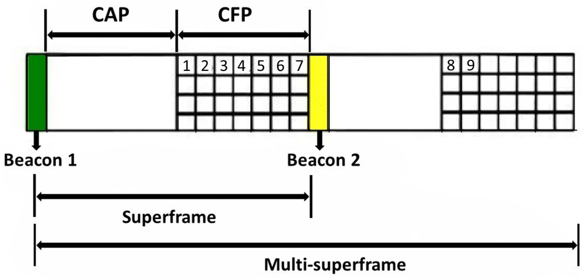
The Deterministic Synchronous Multi-channel Extension (DSME) of IEEE 802.15.4 stands out from the remaining MAC behaviours because of its features such as multi-channel access and support for both contention-based and contention-free traffic, which increases the overall robustness, flexibility and scalability while still providing deterministic communication. These properties also make it an interesting target for deployment of hidden TCCs, particularly, as it supports multiple packet transmissions in a single tightly timed, guaranteed timeslot. The DSME network is time-synchronised by the multisuperframe structure (Figure 4). The rows that span across the multisuperframe indicate the channels and the columns that represent the timeslots. Every superframe within a multisuperframe consists of a Contention Access Period (CAP), that uses CSMA/CA for data transmission, and a Contention-Free Period (CFP), that uses Guaranteed Timeslots (GTS). Every GTS accommodates the transmission of data and an eventual acknowledgment. To allow for a finite amount of time for the MAC layers to process the received data, two successive frames transmitted from a device are separated by at least an IFS period. The length of the IFS period is dependent on the size of the frame that has just been transmitted and can be macSifsPeriod (12 symbols) for shorter frames or macLifsPeriod (40 symbols) for longer frames.
The superframe is defined by BO, the Beacon Order, which specifies the transmission interval of a beacon that delimits the beginning of a superframe. MO is the Multisuperframe Order that impacts the Enhanced Beacon (EB) interval of a multisuperframe, and SO is the Superframe Order that specifies the size of a superframe.
The standard defines the structure of the superframe by the values of Superframe Duration (SD), Multisuperframe Duration (MD) and the Beacon Interval (BI). The Multisuperframe Duration is a new parameter introduced in DSME, as compared to the native IEEE 802.15.4 superframe structure. These parameters are defined in the following equations:
where denotes the minimum duration of a superframe corresponding to . This duration is fixed to 960 symbols, corresponding to 15.36 ms, assuming 250 kbps in the 2.4 GHz frequency band. The total number of superframes and multisuperframes in a DSME superframe structure can be determined by and , respectively. The PAN coordinator sets the values of BO, SO and MO upon network initialisation and are then conveyed to the nodes via Enhanced Beacon at the beginning of each multisuperframe. To further maximise the available guaranteed bandwidth for time critical appplications, CAP Reduction feature was introduced for DSME. This proposal enables the protocol to remove the CAP on all but the first superframe of a multisuperframe, guaranteeing that this initial CAP space is enough for the nodes to exchange allocation requests for the entire multisuperframe (i.e., a node could allocate a timeslot in the second superframe of the multisuperframe). To further increase the performance of the network, the IEEE 802.15.4 DSME protocol provides the CAP reduction flag. If this flag is enabled, then only the first superframe of the multisuperframe will have the CAP space, while all the other superframes will have the beacon slot occupied and all remaining slots will be dedicated to guaranteed timeslots in the CFP portion of the superframe.
4. System Design and Implementation
We created a TCC in the DSME by manipulating the inter-arrival time () of DSME–GTS transmissions, in accordance with the equation below:
The inserted covert channel delay in symbols can be computed as the sum of the standard inter-frame spacing () with the (in symbols) encoding the covert data. The can be further multiplied by an factor which represents the granularity of the delay to be introduced. The can then be converted into milliseconds. For some implementations, it may be hard to decode codes which only differ by a symbol in length, due to performance issues; hence, one can increase its granularity by a scaling factor of . In this work, we also present results in such cases to explore the limitations that some implementations can introduce.
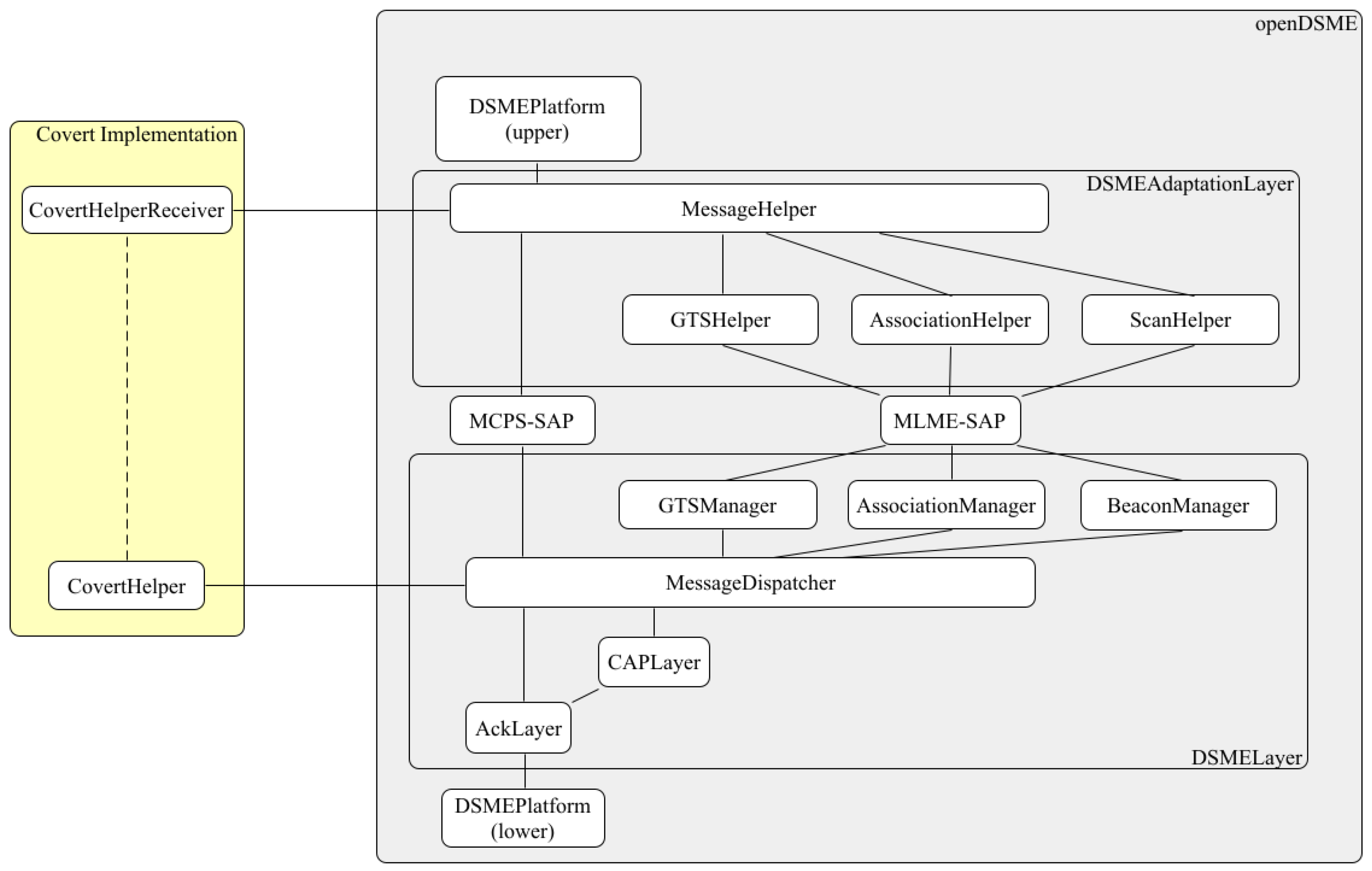
To achieve this, we implement three different kinds of timing covert channels over the DSME–GTS mechanism of the IEEE 802.15.4 in a single-hop communication architecture. Such a mechanism supports contention-free traffic, thus providing improved delivery guarantees and time-bounded communication. Due to these timing properties, this mechanism presents itself as great prey for such time-based covert exploits. The implementation and assessment of the covert channels relies on the IEEE 802.15.4 openDSME simulation model [39], which was deployed over the OMNeT++ 6.0 event simulation framework, supported by the INET platform v4.3.7. This model is composed of two fundamental layers integrated into the MAC link layer: the DSMELayer and the DSMEAdaptionLayer (Figure 5). The first is responsible for implementing the newly released DSME MAC behaviour and all its features, while the adaption layer implements the base IEEE 802.15.4 functions required to perform a cohesive link with the rest of the OSI layers. The higher layer communicates with the lower DSME layer through two interfaces known roughly as Service Access Points (SAP). The DSMEPlatform module is responsible for harmonising the whole model, interconnecting both the DSMELayer and the DSMEAdaptionLayer. The model (at https://bitbucket.org/ricardoseverino/154_gts_ctc, accessed on 21 July 2023) is described in more detail in [39] and overviewed in Figure 5. To fully encapsulate the covert channel implementation in the openDSME model, two new modules were created: (1) the Covert Helper, responsible for the transmission of the messages with covert information and, as such, inserting time delays into the network and (2) the Covert Helper Receiver, in charge of interpreting the information being transmitted in the subliminal channel, by calculating the timing interval between received packets and, with that value, decoding the information being covertly transmitted. It is important to highlight that, for such an exploit to work, only the transmitter must be compromised and fitted with the Covert Helper module. Any other node or IEEE 802.15.4 radio can then serve as receiver and listen to the ongoing transmission in promiscuous mode to decode the information.
4.1. Covert Helper
From the sender’s perspective (Algorithm 1), the covert message to be transmitted must be defined in the initialisation of the module for each new transmission. To facilitate the performance analysis, the same message is continuously transmitted in a loop but it can be changed at any time. To better illustrate the behaviour, we consider that we are transmitting a string of characters. At the beginning of each new covert message transmission, a start delay is introduced at the first transmission opportunity to signal the start of a new covert transaction. The algorithm must then deconstruct the covert message into bits, which are then translated into delays, which are multiple of the protocol symbol duration. In the illustrated example, we consider an On/Off type of covert channel. The first character of the message is selected and each bit is transmitted (by introducing a delay between each packet transmitted in the DSME–GTS). The process continues throughout the remaining string.
This algorithm is injected into the MessageDispatcher module of the DSMELayer, more particularly, of the OpenDSME stack, in the sendDoneGTS method. In here, the transmitter node pops messages from the send queue and, in each one, checks the timeslot for available remaining time for packet transmission. This native method was also tweaked in order to account for the covert delay, upon checking if the timeslot had space for a whole packet transmission. A few changes to this algorithm are introduced in the case of the other covert channel techniques. This is discussed below.
| Algorithm 1 Sender’s algorithm |
|
4.2. Covert Helper Receiver
On the receiver’s side (Algorithm 2), a first verification is performed to ensure the packets having their transmission interval scanned were originally sent from the node responsible for sending the covert information. Next, the packet inter-arrival interval is computed. However, to accurately compute it, one must consider the protocol wireless transmission time. Hence, the algorithm computes it, considering the specific packet payload and header size (). The remaining ones are then converted from milliseconds into multiples of protocol symbols (Equation (5)):
where CurrentInterval is computed as current time minus the last covert packet recorded time (in milliseconds), TxTime represents the wireless transmission time of the packet (Header+Payload) and aBaseSuperframeDuration is the constant that specifies the minimum superframe duration in the protocol. With this value, it is then possible to compute the covert delay inserted between the received packets. Afterwards, a simple comparison with the known encoding values is sufficient to determine the bit being covertly transmitted in the channel, or the initialisation of a new transmission, which resets the storing variables. After a correct reception, the algorithm saves the received covert information and proceeds to the next packet, restarting the process. Depending on the TCC technique used, the algorithm will search different delay lists in order to decode the received covert bit (or set of bits).
In what follows, we describe particular implementation considerations to support the three kinds of timing covert channels analysed.
| Algorithm 2 Receiver’s algorithm |
|
4.3. Specific TCC Implementation Details
On–Off Covert Channel: We implement a binary timing covert channel by manipulating the packet inter-arrival time during a DSME–GTS slot, as presented in Figure 1. To maintain compatibility with the standard timing granularity, we make use of the protocol’s symbol duration as the basic timing unit. This is the smallest amount of simulation time available and recognised by the simulation framework, corresponding to the minimum spacing between each frame. We use a length of two symbols to transmit a binary “one” and a single for a binary “zero”, i.e., standard inter-frame spacing. To signal the beginning of a new transmission, a delay of three symbols is also introduced. When the receiver computes this delay, it resets the covert channel mechanism and begins a fresh reception. The algorithm records the packet inter-arrival time, retaining the inserted delay corresponding to the hidden information. The conversion is then performed from milliseconds to symbols to decode the covert information, which is saved; the channel is then prepared for the next packet reception.
L-Bits to N-Packets Covert Channel: A correlation between the covert information to be transmitted and their associated delay is performed at the start, and must be known by the transmitting and receiving sides. For instance, a set of two bits (00) can be assigned to a delay of 2 symbols, set (01) to 3 symbols, set (11) to 4 symbols, etc. From this association, the algorithm finds the next bits to transmit from the full message, obtain their corresponding delay and insert it into the packet’s timing. On the receiving side, similarly to the On–Off covert channel technique, the inserted delay is obtained and decoded using the pre-arranged table containing the association between delays and covert bits.
Time Replay Covert Channel: Its implementation is rather similar to the L-Bits to N-Packets technique. The main difference is on the transmitter side, where the correlation table is now a matrix containing the several possible delays for the same covert bit set, and a Random Number Generator is implemented in order to determine the interval to be used (from the possible three) in the upcoming transmission. The receiver then retrieves the delay value and performs a row search of the matrix until the recorded delay value is found, as well as the associated covert data. Such a technique may help in escaping automated analysis algorithms that look for inter-arrival pattern repetition, while also making it harder to decode the covert information.
4.4. Simulation Setup
The implementation performed in the openDSME model [39] was run in the OMNeT++ 6.0 rc1 event simulation framework, supported by the INET platform. We considered a star network topology with 11 nodes, organised in a circular shape, where the distance between the exterior nodes and the node [0], i.e., the PAN Coordinator, was similar. This node, being placed at the center, acts as a sink, as presented in Figure 6. Such network size allows us to set up adequate network parameters for the analysis. The default setup of the simulation (unless changed for a specific metric comparison) considers a packet payload length of 1 byte, a varying data rate of 0.01 to 3 s per packet created and a channel bitrate of 250 k bits per second. The chosen data rate values are intended to cover a wide range of different application scenarios, from intensive high-data rate applications such as real-time structural health monitoring [40] or aircraft active flow control [41] to much more relaxed environmental monitoring scenarios. In terms of the protocol standard constants, the beacon order was set to 6, multisuperframe order was 5 and the superframe order was 4. We considered for all test cases and , to guarantee that we allocated two superframes per multisuperframe. This is enough to schedule all nodes’ transmissions in a single multisuperframe, with one GTS slot for each node, as presented in Figure 7 for nodes 1–9. For each simulation scenario, we retrieve several metrics such as the number of bytes of overt traffic transmitted (supporting GTS packets), the amount of information sent covertly (covert data in bytes), the interval between packets in the guaranteed timeslot and the interval between timeslots in which the covert node is transmitting.
5. Results
5.1. Metrics and Information Sources
To assess the performance of the TCC techniques, we considered the following metrics:
- Covert Channel Efficiency, which is represented as the fraction of covert traffic successfully transmitted over the total overt traffic in the GTS slot during the simulation. It informs the impact of the covert channel in the network, in terms of transmission delays;
- Covert Channel Capacity, which measures the amount of covert information successfully transmitted in the covert channel per second of simulation time.
We disregard headers in all metrics. A more efficient covert channel makes better use of the available overt traffic for communication, while higher Covert Channel Capacity naturally translates higher covert channel throughput and, possibly, better data exfiltration capacity. This greatly helps to better understand the risk of such techniques.
In what follows, we first analyse the least complex TCC technique. This enables the reader to better grasp what is at play. We then repeat a similar analysis for the more complex TCC techniques and draw a comparison between all. For each technique, we first analyse the impact of the SO parameter upon these metrics for different traffic generation rates (TGR) from 0.01 s up to 3 s, covering most possible application scenario data-rate demands. Then, we analyse the effect of the packet payload length. To finalise, we then identify some key recommendations that can be introduced to reduce the covert channel impact.
5.2. On/Off Technique
We considered a single On/Off covert channel, established on node [1] to exfiltrate data, corresponding to the slot indicated in the Figure 7. Each simulation ran for 200 s in order to retrieve a data point to compute the needed performance metrics as we changed the relevant network settings. Although the implementation of such a covert technique at the PAN Coordinator, in a bidirectional fashion could potentially give the attacker control over the entire network, we considered the case of a unidirectional CC for the analysis.
5.2.1. Impact of SO upon the Covert Channel
To evaluate the behaviour of the covert channel, we considered varying traffic rates from 0.01 to 3 s. To understand the impact of the SO length upon the scenarios, we tested the MO, SO and BO combinations represented in Table 1.
Figure 8 present and overview of the On/Off TCC performance for each SO setting (SO 4 to 10). For each, we separately depicted the overt, or legitimate, traffic throughput and the covert traffic throughput for different Traffic Generation Rates (TGR). In addition, we also presented the CC Efficiency across the TGRs (black dashed line).
At its best, the binary covert channel was able to achieve a CC Efficiency of 11.9% in regards to the overall legitimate traffic transmitted (for SO = 6 and above). However, as expected, such efficiency decreases as the supporting overt generated traffic is reduced. Particularly, for lower SO, this results in an abrupt decline in CC Efficiency. This means that, although legitimate traffic is being transmitted, it is not able to support the covert channel. The frequent GTS slots, due to the lower SO, dispatch the overt traffic with shorter delays, which prevents the accumulation of packets to avail the GTS service. This reduces the efficiency of the TCC channel, which relies on the manipulation of the inter-arrival time between transmissions. For larger SO (SO > 8) the network can maintain a good CC Efficiency throughout the TGRs, even when the amount of traffic decreases to 1 packet every 3 s, e.g., SO = 10, CC Efficiency above 10%.
Interestingly, if we pick a high TGR such as 0.01 s, we observe that, for small SOs (SO = 4), only a small portion of the amount of traffic sent is relevant for covert traffic, i.e., 7.3% CC Efficiency. This is tightly connected with timeslot length. The reduced GTS duration at SO = 4 (15.36 ms) forces the binary covert channel to resume service on the next superframe, discarding the last sent packet. Naturally, the amount of packets discarded is higher the more resets the covert channel mechanism has to perform. Comparing with SO = 8, we observe that, although they present similar CC Capacity for TGR = 0.01, CC Efficiency is higher on the latter. This means more overt transmissions are needed for lower SO to achieve the same CC Capacity.
Regarding CC Capacity, it is, therefore, clear that choosing a good compromise between SO and the traffic-rate is fundamental. For lower SO values, e.g., SO = 4 and SO = 5, as overt traffic decreases per GTS slot, no covert information can be conveyed at all. This is because there are not enough packets accumulated in each slot for transmission, and, instead, the generated packet is dispatched almost immediately (due to the short GTS periodicity), while the next superframes remain unoccupied until a new packet is generated. However, for higher SO values, the channel can better cope with scarce traffic as, due to its longer superframes, delay is higher and packets become accumulated while awaiting service. In addition, given the higher slot length, more packets can be transmitted in a single slot. However, CC Capacity remains low for higher SO.
Figure 9 aggregates the CC Capacity results for all network setting combinations in Table 1 against different TGRs. As shown, regarding the above mentioned SO/TGR balance, SO = 6 seemed to provide the best results for TGR = [0.01, 0.05], achieving 0.94 covert bytes per second. Lower SOs, due to the small GTS size, cannot transmit many packets per slot, which are needed to support the binary covert channel. Although for SO = 6, there is a higher delay between slots than for lower SOs, its larger slot size allows for more traffic to be transmitted per slot, leading to fewer resets, which increases covert channel capacity. However, for TGR = 0.1 s, SO = 7 seemed to be more suited, as presented in Figure 9, achieving 0.60 B/s. Then, SO = 8 achieves the best covert channel capacity at TGR = 0.4. This occurs until traffic generation rate slows down to 0.1 s. Then, SO = 7 achieves better results at the expense of higher delay. This is related to the GTS slot periodicity. Too frequent GTS slots at slower TGR dispatch overt traffic in such a way that the accumulation of packets per slot is decreased, reducing the supporting overt traffic for the binary CC implementation.
Higher SOs, on the other hand, result in lower covert traffic capacity and appear less sensitive to variations in traffic generation rate. For SO = 10, in TGR = [0.01, 0.7], the covert channel capacity does not change significantly with the traffic rate, and, for SO = 12, the covert channel capacity is approximately the same for all traffic generation rates. This is a consequence of the large GTS slot length’s and period, which accumulates sparse overt traffic, hence supporting covert communications, even at low frequency TGR, although with great delay (which in turn impacts the CC Capacity metric, which is computed throughout simulation time). CC Capacity and Efficiency remain approximately constant (Figure 8e,f).
5.2.2. Impact of Packet length
While keeping the same network setup, we next analysed the impact of different packet lengths on the covert channel performance. To carry out this analysis, we started by fixing the SO to 6 and varied the traffic generation rate. Indeed, as shown in Figure 10 for SO = 6, this impact is particularly visible for lower traffic generation periods. For TGR = 0.01 s, an increase in packet length dramatically reduces the covert channel capacity, as, the larger each packet, the less traffic that can fit inside a timeslot, thus decreasing the available overt support traffic for the binary covert channel. As the amount of traffic decreases, the longer packets decrease their impact upon the covert channel capacity. This is because the number of packets transmitted in each slot is already so low that the longer packet size does not significantly change the amount transmitted per slot.
We next studied the impact of packet length at different SOs and learned, regarding the covert channel, the effect of increased packet lengths on covert channel capacity is particularly worse for lower SOs, as shown in Figure 11 for TGR = 0.01. The already shorter timeslots now further reduce service by half, for the case of 75 bytes packet length. The dramatic decrease in packets effectively transmitted naturally reduces the capacity of the timing covert channel, as already analysed in the previous section. However, for larger SOs, the effect of packet length is negligible, even at such high traffic generation rates. This immunity is related to the large GTS timeslot length, which is sufficient to accommodate all the generated traffic.
It is also worthwhile to analyse the impact of packet length upon the Covert Channel Efficiency metric. As observed in Figure 12, the increase in packet length results in a decrease in the CC Efficiency metric throughout different SOs. The larger packets generate an increased amount of delivered overt traffic, which decreases the CC Efficiency ratio, as the covert traffic remains approximately the same and much smaller, in comparison to the overt counterpart. Low CC Efficiencies are thus expected, as the TCC works by taking advantage of overt traffic, which is produced in larger amounts. However, for fair usage of the metric, CC Efficiency should be compared only at the same packet lengths.
5.3. Analysis of More Complex TCC Techniques
To better understand the performance limits of GTS TCC over this protocol, the other relevant techniques were also analysed. The Time Replay and the L-Bits to N-Packets techniques provide additional efficiency via improved coding of the covert data, achieved by supporting additional packet inter-arrival intervals to code 2, 4 and 8 bit sets at a time.
Figure 13 depicts the CC capacity for such implementations at different covert data encoding lengths (2, 4 and 8 bits). Regarding CC capacity, as presented in Figure 13, the techniques that encode 8 covert bits per single packet inter-arrival interval present the highest capacity. However, even when encoding 2 bit sets of covert traffic, the CC capacity doubled, reaching approximately 2 B/s for SO = 6 (Figure 13a,b), while, with the On/Off technique, we could reach a maximum of 0.94 B/s (Figure 9). The best CC capacity was reached for 8 bit TCC encoding techniques at SO = [6, 7], achieving 5.8 B/s for high traffic rates of TGR = [0.01, 0.05].
As expected, the abundance of supporting overt generic traffic in the network allows for an increase in the covert traffic and, therefore, the highest recorded values are related to a TGR of 0.01 s. Comparing superframe orders, we observe that an extremely low or high superframe order can negatively impact the CC capacity. This is, on the one hand, due to the reduced size of the guaranteed timeslots (lower superframe orders) and, on the other hand, to the longer period that separates GTS timeslots because of the longer superframes (high superframe orders).
Clearly, the increase in CC capacity from the 4 and 8 bit TCC techniques is quite significant. In Figure 14, we compare CC efficiency for the different techniques at SO = 6. Clearly, the 8 bit techniques reach CC efficiency close to 96%. This implies that we are reaching the point at which the TCC conveys a byte of covert information for each byte of regular overt traffic transmitted. Naturally, the least efficient technique is the On/Off, followed by the 2 bit encoding techniques, showing close to 24% CC efficiency.
Given this information, one could easily argue that the more bits of information one can encode into the covert interval, the better. This will result in larger CC efficiency, CC capacity and, therefore, higher capacity for data exfiltration. However, such an approach can also increase the detectability of the covert channel due to large overt traffic delays.
Figure 15 presents the inter-arrival time between consecutive covert transmissions, that is, the amount of delay inserted into each legitimate packet to encode and transmit the desired covert information for each technique. We considered SO = 10 for all cases.
A manipulation of the inter-arrival time between GTS transmissions on the order of a couple of symbols, as in the case of the On/Off TCC technique, can easily pass unnoticed, as it will not heavily impact the delay, i.e., 3 symbols approximately equals 0.096 ms, on top of 12 or 40 symbols of the SIFS or LIFS. That is also the case for the L-Bits to N-Packets (2 bit) technique. The increase in delay is minimal but already sufficient to almost double the CC capacity in comparison with the On/Off. The Time Replay (2 bit) technique, however, already further increases the delay. This is because it will provide additional codes for the same data, hence increasing the delay. As shown in Figure 13, the Time Replay technique does not provide any improvement in terms of CC capacity. However, by using different codes for the same piece of covert information, the decoding of the covert information by security personnel may become difficult. The same principle applies as we use 4 bit encoding techniques, although one can remain bellow the 3 ms delay between packets. For the 8 bit techniques, however, the delay starts becoming too noticeable. This is particularly visible for the Time Replay technique, which relies on a quite large set of encoding intervals and may reach delays over 12 ms between overt data transmissions. This naturally decreases the amount of traffic that can be conveyed per GTS slot, meaning, in some cases, it will be unfeasible to implement, depending on the granularity of the encoding interval unit ().
5.4. Impact of the TCC Encoding Interval ()
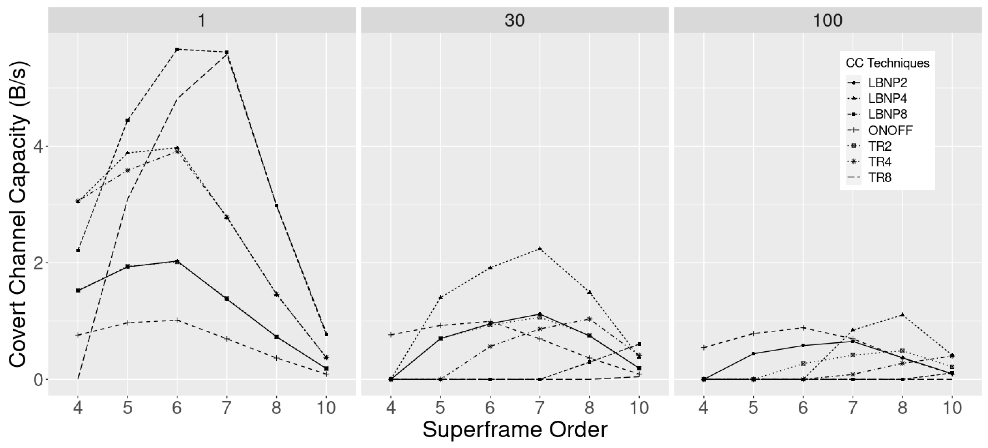
As mentioned before, the timing covert channels rely on a minimum interval to encode information. Such a value for was chosen as the duration of one symbol (around 0.016 ms). Hence, multiples of this unit were used to encode the different covert data sets. We understand this unit to be implementation specific. There may be cases in which, due to hardware or processing limitations, longer values must be used. However, this poses a significant impact upon the performance of the TCC, and, in some cases, some SO settings will not be able to support some TCC techniques. In this section, we decided to explore this impact, to better understand the behaviour of such techniques for of 1 symbol, 30 symbols and 100 symbols, which correspond to 16 s, 480 s and 1.6 ms, respectively.
For these simulations we kept a TGR of 0.01s to guarantee a good amount of supporting traffic and evaluated the different techniques’ CC capacity at different SO. As shown in Figure 16, the profile for is the same as found in previous results, reaching approximately 6 B/s CC Capacity for the longer encoding techniques of LBNP8 and TR8, and the worst performance for the On/Off case. However, at symbols, we observe a significant performance drop among all techniques, as longer inter-arrival periods are needed to encode the same information due to the increase in . TR8 cannot be sustained with SO between 4 and 10, as the GTS slot size is too short to accommodate the long delays between packets. The LBNP8 can only be supported at .
Interestingly, at SO = 4, only the On/Off technique can be supported with such , and at SO = 5 the LBNP4 technique is the only one that outperforms On/Off, despite LBNP2 and TR2 is also supported. TR4 is only available for SO > 5 and LBNP8 for SO > 7. As of SO > 6, the On/Off technique starts under-performing with respect to the other techniques. With increasing superframe size and, thus, GTS slot length, larger covert encoding intervals can be accommodated between the packets, meaning techniques with larger encoding capabilities (2, 4 and 8 bit) start gaining in CC Capacity. On the other hand, the increasing period between the GTS transmission opportunities, lowers the CC Capacity for the other techniques. Effectively, at SO = 10, LBNP8 surpasses all other techniques in CC Capacity, slightly compensating for the large superframe period with higher covert bit encoding for each interval. As we increase to 100 symbols, CC Capacity drops even further for all techniques (as expected). Again, only the On/Off binary technique can support covert traffic at SO < 5. However, as the SO increases, the On/Off cannot support CC Capacity above 1 B/s. LBNP4 is supported for SO > 6 and surpasses the On/Off technique CC Capacity due to its larger encoding format.
We conclude that larger encoding techniques do not necessarily increase the CC Capacity if large is selected, due to implementation constraints. Indeed, simpler, binary techniques such as the On/Off can outperform these for mid-range SO (4 < SO < 8) for large of 100 symbols. For larger SO > 7 and large , the higher bit encoding capacities of the more complex TCC techniques start to gain more prominence due to the longer periods between GTS slots. Still, the overall CC Capacity decreases substantially with the increase in (6 fold for of 100 symbols), as less covert data fit inside each slot due to the increase in the inserted interval length. Hence, as increases above 100 symbols, higher bit encoding techniques do not provide a very significant advantage and, on the contrary, may be easier to detect due to the introduction of very large delays in GTS data.
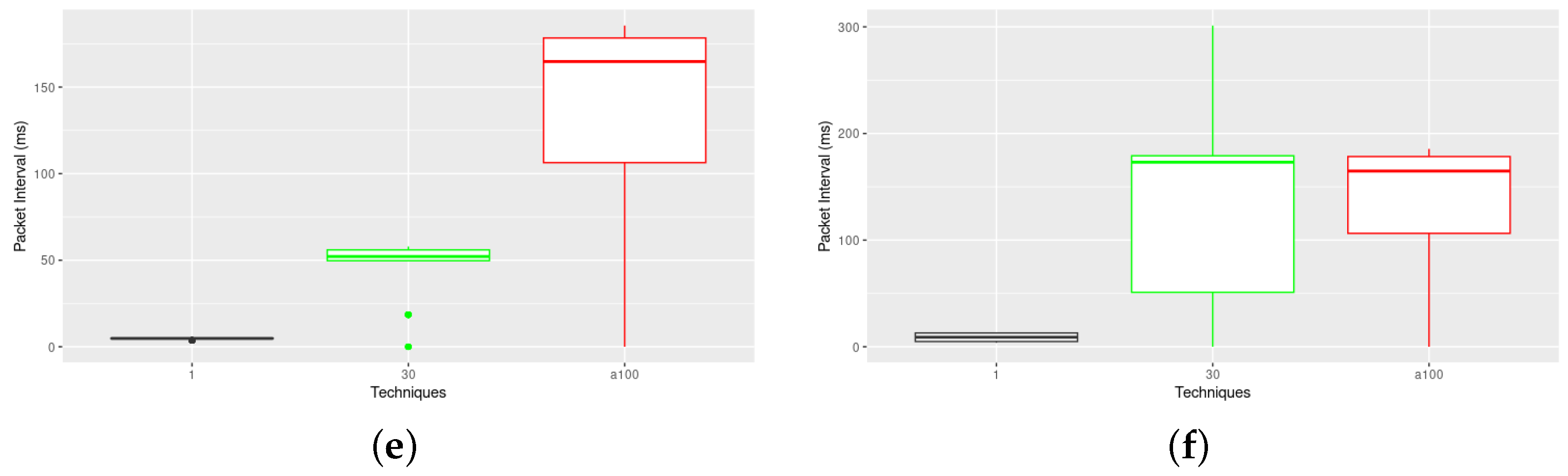
To better illustrate this effect, Figure 17 presents the packet inter-arrival time for each technique with different encoding capabilities and different . Focusing, for instance, on the LBNP techniques, it is clear that the LBNP techniques introduce less delay than the TR. For instance, in Figure 17f, we see that it was not possible to fit the covert delays introduced by the TR8 technique at = 100 into a timselot. This is because TR introduces different code words for the same data, thus resulting in increased delays. For the LBNP2, there is not a significant increase in delay with increase in . There are only 4 encoding possibilities, hence the impact is limited. However, it becomes clear that, as the enconding capabilities increase, the impact becomes much larger, from 4 ms for = 1 to 13 ms for = 100, and, for the LBNP8, from 12 ms for = 1 to 50 ms for = 30 and 160 ms for = 100. Notably, 160 ms average packet delay is very much significant, and, as shown in Figure 16, this does not translate into a significant improvement for SO = 10 with regard to LBNP4, which presents 13 ms. For lower = 30, LBNP8 shows a 10-fold increase in inter-arrival delay with regard to LBNP4 just results in a 0.2 B/s improvement in CC capacity, again at SO = 10. However, at lower , clearly, the usage of higher encoding techniques is worthwhile as it does not translate into high inter-arrival delays. This can be visualised better in Figure 18, which depicts the packet inter-arrival delay at different , concerning the different TCC techniques. As depicted, the Time Replay techniques are indeed the most affected by the increase in , due to the multiple redundant encoding values, while LBNP shows much lower delays, even with LBNP4 lower that TR2 at .
Covert Channel Impairment
It is clear that such convert implementations can become quite concerning, despite the low throughput. At moderate overt traffic rates, i.e., 0.1–0.4 packets/s, and with a very naive CC On/Off implementation (i.e., not the most efficient in terms of data encoding), it takes from 50 s to a couple of minutes to exfiltrate a 256 bit key using such a covert channel approach. However, if a higher bit encoding technique is used, such as TR8, this can be performed in under 6 s. This is how much time it can take to defeat many encryption techniques, permanently and almost covertly, if such a TCC is in place, even if the network manager frequently changes encryption keys. Moreover, only the transmitter must be compromised for the covert channel to work, as any other node or IEEE 802.15.4 radio can then serve as receiver and listen to the ongoing transmission in promiscuous mode to decode the information. Indeed, even if encryption is in place, the timing characteristics of the MAC remain; thus, covert information is transmitted independently of the strength of the encryption algorithm used to encrypt the payload.
Furthermore, the TCCs were implemented in a single slot; however, by placing such an exploit at the PAN Coordinator, the TCC could span over every slot transmission, multiplying the effectiveness of the mechanism. The conclusions taken from this simulation study enable us to better understand the risks such techniques pose for IIoT devices which rely on this protocol. In addition, we have learned that, by tuning specific network parameters, we can cut down on the performance of such covert timing implementations. Such strategies should be explored in an effort to defeat their data exfiltration capabilities. Figure 19 compares the data exfiltraton capabilities (CC capacity) between several superframe orders and traffic generation rates using the On/Off technique to summarise the findings; this principle is applicable to all other techniques.
The TCC performance is highly dependent on the overall balance between slot length (slot periodicity), specified by the SO and MO settings, and traffic generation rate. We observed that using low SO values with low packet generation rates can effectively defeat such timing covert channel implementations, or greatly reduce their performance, while still guaranteeing low legitimate traffic delays. The higher frequency of the superframes reduces the probability of transmitting several packages per GTS slot, creating starvation of the TCC. Such a strategy will work, of course, at the expense of higher energy consumption, as superframes become more frequent. This is observed for SO = [3, 4]. On the other hand, higher SO values, although they are unable to provide high CC Capacity, can accommodate greater shifts in traffic generation rate, even when applications generate very little traffic.
Hence, recommendations for preventive measures would be as follows:
- Restrict small packet lengths: Packet length affects the CC performance metrics, particularly for lower SOs. Higher packet lengths reduce the traffic that can fit in each GTS slot, which reduces CC transmission opportunities. On the other hand, smaller packets may lead to more frequent transmissions, which creates more TCC transmission opportunities. Relying on padding techniques to deal with small data portions, if really needed, can and should be considered as a preventive measure to reduce exfiltration capacity;
- Decrease SO to the minimum: The smaller the SO, the higher the periodicity of slots, and, if there are no available packets to transmit in that slot, no covert information can be transmitted. As shown, high SOs are more flexible and can cope with very low frequency traffic while still managing to convey covert information. This should be paired with the next recommendation;
- Decrease traffic generation frequency: Frequent generation of packets for transmission increases the TCC opportunities. If low SOs are used and a TGR > 0.4, one can heavily impair these TCC implementations;
- Pay attention to any increase in packet inter-arrival times: Such TCCs work by inserting variable intervals between packet transmissions. Larger TCC bit encoding techniques tend to insert non-negligible delays between frames, which can be noticed as a sudden increase in delay.
6. Conclusions
6.1. Lessons Learned
Covert Channels have been receiving increased attention in the cyber-security communities, due to the long term risks such implementations can present to compromised devices and networks, particularly by supporting undetected data exfiltration or botnet orchestration. In the IIoT domains, this is even more critical, as devices typically present more vulnerabilities which can be exploited by such techniques, providing a foundation to further escalate attacks. In the particular case of IEEE 802.15.4, although this set of protocols is quite pervasive in enabling many IIoT communication stacks, insufficient attention has been given to this concerning problem.
The pervasiveness of the IEEE 802.15.4 protocol and the timing properties of the GTS mechanism of the DSME MAC behaviour make it a very interesting target for such cloaked time-based constructions. In this work, we observed how feasible it is to implement a series of timing covert channel techniques over the GTS communication mechanism and carried out a thorough performance analysis regarding the impact of different networking settings, exploring their limitations. We verified such TCC techniques are indeed concerning and identified some actions that may help mitigate the impact of such CC implementations by stopping or reducing their data exfiltration capacity. This can be achieved at the MAC level via manipulation of a few settings as a preventive measure. Particularly, there is a strong impact on the TCC performance due to available slot size and periodicity, which depend on SO configuration and the available traffic generation rate. The impact of different packet payload lengths was also measured and compared, according to previous metrics. The payload length caused the most impact on networks with high traffic, whereas the smallest packets could pass more information covertly due to more frequent transmissions. However, as the traffic in the simulation scenario diminished, the impact of different payload packet lengths was viewed as insignificant and unable to impact the covert channel in a significant fashion.
We achieved covert traffic capacities from 1 B/s for the most naive binary TCC implementation, up to 6 B/s with the most complex ones, which support higher bit encoding capabilities. It is clear that higher bit encoding techniques can achieve higher covert transmission capacity, albeit at the cost of higher network delays. Such delays may become unfeasible for very small GTS slot sizes (low SO); however, 4 bit encoding techniques seem to provide a very good support across most of the common SO spectrum, without a significant impact upon the network delay when compared to other techniques. However, there is a clear dependency on the granularity of the CC interval (we refer to this as ), which may enlarge due to limitations in the implementation.
6.2. Further Research
We believe this work is fundamental for IoT network designers and security experts to assess TCC risks and to further support the development of detection and mitigation strategies, for which our implementation can also be of great help. First, with the performance analysis we carried out, the IoT and cyber-security communities can now be alert and aware of the information exfiltration capacity of these exploits. Second, the provided simulation model with three TCC implementations can now support the direct development of mitigation mechanisms by leveraging the OmNeT++ simulation model, which greatly facilitates thorough preliminary assessment of functionality.
Experimental deployments of such techniques can and should be carried out in the near future to further validate these results. Such deployments are now eased by our work, as we relied on a simulation stack, supported by the RIOT operating system, that can be directly ported to several IoT platforms. Naturally, we expect to observe limitations regarding combinations of low SOs and high data rates, particularly due to performance limitations of some platforms. Indeed, the granularity we introduced and analysed in this work will become particularly useful in such cases, by relaxing the covert channel temporal requirements.
Finally, although concerning, covert channels can also be explored in a beneficial way to improve the security of these systems. One such example relies on the implementation of cloaked authentication mechanisms, which can guarantee a legitimate origin of the IoT message in a lightweight fashion. Such a mechanism would bring another unforeseen advantage: in addition to achieving another layer of security, we can also mitigate any exploitation of such a covert channel with any malicious intent, as such usage would disrupt the covert authentication protocol in place. We expect such covert channels can be used in authentication and authorisation mechanisms; towards this, understanding the performance limits of these implementations is fundamental. Hence, our contribution also provides this support, enabling innovative usages of such covert transmission opportunities. A preliminary study of such an authentication mechanism has already been performed, and we will provide any interesting findings in a subsequent publication.
Author Contributions
Conceptualization, R.S.; Methodology, R.S., J.R. and L.L.F.; Software, J.R.; Validation, J.R. and J.A.; Investigation, R.S. and J.R.; Data curation, J.R. and J.A.; Writing—original draft, R.S. and J.R.; Writing—review & editing, R.S. and L.L.F.; Visualization, J.A.; Supervision, R.S. and L.L.F.; Project administration, R.S. All authors have read and agreed to the published version of the manuscript.
Funding
This work was partially supported by the Norte Portugal Regional Operational Programme (NORTE 2020), under the PORTUGAL 2020 Partnership Agreement, through the European Regional Development Fund (ERDF), within project “Cybers SeC IP” (NORTE-01-0145-FEDER-000044); also by the OPEVA project that has received funding within the Key Digital Technologies Joint Undertaking (KDT JU) from the European Union’s Horizon Europe Programme and the National Authorities (France, Belgium, Czechia, Italy, Portugal, Turkey, Switzerland), under grant agreement 101097267. Views and opinions expressed are however those of the author(s) only and do not necessarily reflect those of the European Union or KDT JU. Neither the European Union nor the granting authority can be held responsible for them.
Data Availability Statement
Data sharing not applicable: Presented simulation results can be replicated by usage of the provided simulation model. Data sharing is not applicable to this article.
Conflicts of Interest
The authors declare no conflict of interest.
Abbreviations
The following abbreviations are used in this manuscript:
| IoT | Internet of Things |
| IIoT | Industrial Internet of Things |
| D-DoS | Distributed Denial of Service |
| IEEE | Institute of Electrical and Electronics Engineers |
| MAC | Media Access Control |
| DSME | Deterministic and Synchronous Multichannel Extension |
| TSCH | Time Slotted Channel Hopping |
| GTS | Guaranteed Timeslot |
| PDU | Protocol Data Unit |
| LAN | Local Area Network |
| DSSS | Direct Spread Spectrum Sequence |
| LQI | Link Quality Indication |
| WSN | Wireless Sensor Network |
| CAP | Contention Access Period |
| CFP | Contention Free Period |
| BO | Beacon Order |
| MO | Multisuperframe Order |
| SO | Superframe Order |
| EB | Enhanced Beacon |
| SD | Superframe Duration |
| MD | Multisuperframe Duration |
| BI | Beacon Interval |
| PAN | Personal Area Network |
| OSI | Open Systems Interconnection |
| SAP | Service Access Points |
| TGR | Traffic Generation Rate |
| CC | Covert Channel |
| TCC | Timing Covert Channel |
References
- U.S. Department of Defense. DoD Policy Recommendations for the Internet of Things (IoT); U.S. Department of Defense: Washington, DC, USA, 2016.
- Al-Turjman, F.; Nawaz, M.H.; Ulusar, U.D. Intelligence in the Internet of Medical Things era: A systematic review of current and future trends. Comput. Commun. 2020, 150, 644–660. [Google Scholar] [CrossRef]
- Sinha, A.; Shrivastava, G.; Kumar, P. Architecting user-centric internet of things for smart agriculture. Sustain. Comput. Inform. Syst. 2019, 23, 88–102. [Google Scholar] [CrossRef]
- Muñuzuri, J.; Onieva, L.; Cortés, P.; Guadix, J. Using IoT data and applications to improve port-based intermodal supply chains. Comput. Ind. Eng. 2020, 139, 105668. [Google Scholar] [CrossRef]
- Wang, J.H. T cell receptors, mechanosensors, catch bonds and immunotherapy. Prog. Biophys. Mol. Biol. 2020, 153, 23–27. [Google Scholar] [CrossRef] [PubMed]
- Liu, K.; Bi, Y.; Liu, D. Internet of Things based acquisition system of industrial intelligent bar code for smart city applications. Comput. Commun. 2020, 150, 325–333. [Google Scholar] [CrossRef]
- Statista. Number of IoT Devices 2015–2025. Available online: https://www.statista.com/statistics/471264/iot-number-of-connected-devices-worldwide/ (accessed on 24 July 2022).
- Lin, J.; Yu, W.; Zhang, N.; Yang, X.; Zhang, H.; Zhao, W. A Survey on Internet of Things: Architecture, Enabling Technologies, Security and Privacy, and Applications. IEEE Internet Things J. 2017, 4, 1125–1142. [Google Scholar] [CrossRef]
- Frustaci, M.; Pace, P.; Aloi, G.; Fortino, G. Evaluating Critical Security Issues of the IoT World: Present and Future Challenges. IEEE Internet Things J. 2018, 5, 2483–2495. [Google Scholar] [CrossRef]
- Lu, S.; Chen, Z.; Fu, G.; Li, Q. A Novel Timing-based Network Covert Channel Detection Method. J. Phys. Conf. Ser. 2019, 1325, 012050. [Google Scholar] [CrossRef]
- Liu, Z.; Liu, J.; Zeng, Y.; Ma, J. Covert Wireless Communication in IoT Network: From AWGN Channel to THz Band. IEEE Internet Things J. 2020, 7, 3378–3388. [Google Scholar] [CrossRef]
- Caviglione, L.; Merlo, A.; Migliardi, M. Covert Channels in IoT Deployments through Data Hiding Techniques. In Proceedings of the 2018 32nd International Conference on Advanced Information Networking and Applications Workshops (WAINA), Krakow, Poland; 2018; pp. 559–563. [Google Scholar] [CrossRef]
- SecurityWeek 70 Percent of IoT Devices Vulnerable to Cyberattacks: HP. 2014. Available online: https://www.securityweek.com/70-iot-devices-vulnerable-cyberattacks-hp/ (accessed on 24 July 2023).
- Larson, S. A Smart Fish Tank Left a Casino Vulnerable to Hackers. 2017. Available online: https://money.cnn.com/2017/07/19/technology/fish-tankhack-darktrace/index.html (accessed on 24 July 2023).
- Stanislav, M.; Beardsley, T. HACKING IoT: A Case Study on Baby Monitor Exposures and Vulnerabilities. Rapid7 Rep. 2015. Available online: https://www.rapid7.com/globalassets/external/docs/Hacking-IoT-A-Case-Study-on-Baby-Monitor-Exposures-and-Vulnerabilities.pdf (accessed on 24 July 2023).
- Simon, S. ‘Internet Of Things’ Hacking Attack Led to Widespread Outage of Popular Websites. NPR, 2016. Available online: https://www.npr.org/2016/10/22/498954197/internet-outage-update-internet-of-things-hacking-attack-led-to-outage-of-popula (accessed on 24 July 2023).
- Krebs, B. Mirai IoT Botnet Co-Authors Plead Guilty—Krebs on Security. 2017. Available online: https://krebsonsecurity.com/2017/12/mirai-iot-botnet-co-authors-plead-guilty/ (accessed on 24 July 2023).
- Kolias, C.; Kambourakis, G.; Stavrou, A.; Voas, J. DDoS in the IoT: Mirai and other botnets. Computer 2017, 50, 80–84. [Google Scholar] [CrossRef]
- Cirani, S.; Ferrari, G.; Veltri, L. Enforcing Security Mechanisms in the IP-Based Internet of Things: An Algorithmic Overview. Algorithms 2013, 6, 197–226. [Google Scholar] [CrossRef] [Green Version]
- Riahi Sfar, A.; Natalizio, E.; Challal, Y.; Chtourou, Z. A roadmap for security challenges in the Internet of Things. Digit. Commun. Netw. 2018, 4, 118–137. [Google Scholar] [CrossRef]
- Kim, D.; Choi, J.Y.; Hong, J.E. Evaluating energy efficiency of Internet of Things software architecture based on reusable software components. Int. J. Distrib. Sens. Netw. 2017, 13, 1550147716682738. [Google Scholar] [CrossRef]
- Hu, J.; Lin, C.; Li, X. Relationship Privacy Leakage in Network Traffics. In Proceedings of the 2016 25th International Conference on Computer Communication and Networks (ICCCN), Waikoloa, HI, USA, 1–4 August 2016; pp. 1–9. [Google Scholar] [CrossRef]
- Caviglione, L. Trends and Challenges in Network Covert Channels Countermeasures. Appl. Sci. 2021, 11, 1641. [Google Scholar] [CrossRef]
- IEEE Std 802.15.4-2020; IEEE Standard for Low-Rate Wireless Networks. IEEE: Piscataway, NJ, USA, 2020; pp. 1–800. [CrossRef]
- IEEE Std 802.15.4e-2012IEEE Standard for Local and Metropolitan Area Networks—Part 15.4: Low-Rate Wireless Personal Area Networks (LR-WPANs) Amendment 1: MAC Sublayer; IEEE: Piscataway, NJ, USA, 2012; pp. 1–225. [CrossRef]
- Lampson, B.W. A note on the confinement problem. Commun. ACM 1973, 16, 613–615. [Google Scholar] [CrossRef]
- Wolf, M. Covert channels in LAN protocols. In Proceedings of the Local Area Network Security; Berson, T.A., Beth, T., Eds.; Lecture Notes in Computer Science; Springer: Berlin/Heidelberg, Germany, 1989; pp. 89–101. [Google Scholar] [CrossRef]
- an Tan, Y.; Zhang, X.; Sharif, K.; Liang, C.; Zhang, Q.; Li, Y. Covert Timing Channels for IoT over Mobile Networks. IEEE Wirel. Commun. 2018, 25, 38–44. [Google Scholar] [CrossRef]
- Biswas, A.K.; Ghosal, D.; Nagaraja, S. A Survey of Timing Channels and Countermeasures. ACM Comput. Surv. 2017, 50, 1–39. [Google Scholar] [CrossRef] [Green Version]
- Baker, T.; Liang, C.; Li, Y. A Reliable Covert Channel for Stealthy Data Transmission for Internet-of-Underwater-Things. IEEE Internet Things Mag. 2022, 5, 42–46. [Google Scholar] [CrossRef]
- Liu, B.; Gu, C.; He, S.; Chen, J. LoPhy: A Resilient and Fast Covert Channel over LoRa PHY. In Proceedings of the 22nd International Conference on Information Processing in Sensor Networks, San Antonio, TX, USA, 9–12 May 2023; Association for Computing Machinery: New York, NY, USA, 2023; pp. 1–13. [Google Scholar] [CrossRef]
- Hou, N.; Zheng, Y. CloakLoRa: A Covert Channel over LoRa PHY. In Proceedings of the 2020 IEEE 28th International Conference on Network Protocols (ICNP), Madrid, Spain, 13–16 October 2020; pp. 1–11. [Google Scholar] [CrossRef]
- Vanderhallen, S.; Van Bulck, J.; Piessens, F.; Mühlberg, J.T. Robust authentication for automotive control networks through covert channels. Comput. Netw. 2021, 193, 108079. [Google Scholar] [CrossRef]
- Nain, A.K.; Rajalakshmi, P. A reliable covert channel over IEEE 802.15.4 using steganography. In Proceedings of the 2016 IEEE 3rd World Forum on Internet of Things, WF-IoT 2016, Reston, VA, USA, 12–14 December 2016; pp. 711–716. [Google Scholar] [CrossRef]
- Tuptuk, N.; Hailes, S. Covert channel attacks in pervasive computing. In Proceedings of the 2015 IEEE International Conference on Pervasive Computing and Communications (PerCom), St. Louis, MO, USA, 23–27 March 2015; pp. 236–242. [Google Scholar] [CrossRef]
- Martins, D.; Guyennet, H. Steganography in MAC layers of 802.15.4 protocol for securing wireless sensor networks. In Proceedings of the 2010 2nd International Conference on Multimedia Information Networking and Security, Nanjing, China, 4–6 November 2010; pp. 824–828. [Google Scholar] [CrossRef] [Green Version]
- Tian, J.; Xiong, G.; Li, Z.; Gou, G. A Survey of Key Technologies for Constructing Network Covert Channel. Secur. Commun. Netw. 2020, 2020, 8892896. [Google Scholar] [CrossRef]
- Severino, R.; Rodrigues, J.; Ferreira, L.L. Exploring Timing Covert Channel Performance over the IEEE 802.15.4. In Proceedings of the 2022 IEEE 27th International Conference on Emerging Technologies and Factory Automation (ETFA), Stuttgart, Germany, 6–9 September 2022; pp. 1–8. [Google Scholar] [CrossRef]
- Köstler, M.; Kauer, F.; Lübkert, T.; Turau, V. Towards an Open Source Implementation of the IEEE 802.15.4 DSME Link Layer. In Proceedings of the 15. GI/ITG KuVS Fachgespräch Sensornetze; Scholz, J., von Bodisco, A., Eds.; University of Applied Sciences Augsburg, Department of Computer Science: Augsburg, Germany, 2016; p. 4. [Google Scholar]
- Aguilar, R.; Ramos, L.F.; Lourenço, P.B.; Severino, R.; Gomes, R.; Gandra, P.; Alves, M.; Tovar, E. Prototype WSN Platform for Performing Dynamic Monitoring of Civil Engineering Structures. In Proceedings of the Sensors, Instrumentation and Special Topics; Proulx, T., Ed.; Springer: New York, NY, USA, 2011; Volume 6, pp. 81–89. [Google Scholar]
- Sámano, R.; Viana, J.; Ferreira, N.; Loureiro, J.; Cintra, J.; Rocha, A.; Tovar, E. Active flow control using dense wireless sensor and actuator networks. Microprocess. Microsyst. 2018, 61, 279–295. [Google Scholar] [CrossRef]
Figure 1.
Time Slot diagram of an On/Off covert channel.

Figure 2.
Time Slot diagram of a covert channel of the L-Bits to N-Packets type.

Figure 3.
Time Slot diagram of a covert channel of the Time Replay type.

Figure 4.
IEEE 802.15.4 DSME multi superframe structure (BO = 7, MO = 7, SO = 6).

Figure 5.
OpenDSME architecture and covert modules implementation.

Figure 6.
OMNeT++ Simulator Model.

Figure 7.
Superframe schedule for 10 nodes.

Figure 8.
Regular vs. Covert channel traffic in several Superframe Orders. (a) Superframe Order 4. (b) Superframe Order 5. (c) Superframe Order 6. (d) Superframe Order 7. (e) Superframe Order 8. (f) Superframe Order 10.
Figure 8.
Regular vs. Covert channel traffic in several Superframe Orders. (a) Superframe Order 4. (b) Superframe Order 5. (c) Superframe Order 6. (d) Superframe Order 7. (e) Superframe Order 8. (f) Superframe Order 10.

Figure 9.
Total Covert Bytes transmitted by Traffic Generation Rate and Superframe Order.

Figure 10.
Total Covert Bytes transmitted by Packet Length and Traffic Generation Rate for SO 6.

Figure 11.
Total Covert Bytes transmitted by Superframe Order and Packet Length.

Figure 12.
CC Efficiency per SO at different Packet Lengths.

Figure 13.
CC Techniques capacity comparison for different Superframe Orders and Traffic Generation Rates. (a) L-Bits to N-Packets 2 bits. (b) Time Replay 2 bits. (c) L-Bits to N-Packets 4 bits. (d) Time Replay 4 bits. (e) L-Bits to N-Packets 8 bits. (f) Time Replay 8 bits.
Figure 13.
CC Techniques capacity comparison for different Superframe Orders and Traffic Generation Rates. (a) L-Bits to N-Packets 2 bits. (b) Time Replay 2 bits. (c) L-Bits to N-Packets 4 bits. (d) Time Replay 4 bits. (e) L-Bits to N-Packets 8 bits. (f) Time Replay 8 bits.

Figure 14.
CC Efficiency technique comparison.

Figure 15.
CC Techniques intervals comparison.

Figure 16.
CC Capacity for different techniques (SO and variation).

Figure 17.
CC Techniques packet delay time comparison for different values of . (a) L-Bits to N-Packets 2 bits. (b) Time Replay 2 bits. (c) L-Bits to N-Packets 4 bits. (d) Time Replay 4 bits. (e) L-Bits to N-Packets 8 bits. (f) Time Replay 8 bits.
Figure 17.
CC Techniques packet delay time comparison for different values of . (a) L-Bits to N-Packets 2 bits. (b) Time Replay 2 bits. (c) L-Bits to N-Packets 4 bits. (d) Time Replay 4 bits. (e) L-Bits to N-Packets 8 bits. (f) Time Replay 8 bits.


Figure 18.
Inter-arrival delay for TCC techniques at different .

Figure 19.
CC and Regular Channel Capacity comparison (SO—TGR).


Table 1.
Network DSME configurations.
| SO | MO | BO | |
|---|---|---|---|
| A | 4 | 5 | 6 |
| B | 5 | 6 | 7 |
| C | 6 | 7 | 8 |
| D | 7 | 8 | 9 |
| E | 8 | 9 | 10 |
| F | 10 | 11 | 12 |
| G | 12 | 13 | 14 |
Disclaimer/Publisher’s Note: The statements, opinions and data contained in all publications are solely those of the individual author(s) and contributor(s) and not of MDPI and/or the editor(s). MDPI and/or the editor(s) disclaim responsibility for any injury to people or property resulting from any ideas, methods, instructions or products referred to in the content. |
© 2023 by the authors. Licensee MDPI, Basel, Switzerland. This article is an open access article distributed under the terms and conditions of the Creative Commons Attribution (CC BY) license (https://creativecommons.org/licenses/by/4.0/).
Share and Cite
MDPI and ACS Style
Severino, R.; Rodrigues, J.; Alves, J.; Ferreira, L.L. Performance Assessment and Mitigation of Timing Covert Channels over the IEEE 802.15.4. J. Sens. Actuator Netw. 2023, 12, 60. https://doi.org/10.3390/jsan12040060
AMA Style
Severino R, Rodrigues J, Alves J, Ferreira LL. Performance Assessment and Mitigation of Timing Covert Channels over the IEEE 802.15.4. Journal of Sensor and Actuator Networks. 2023; 12(4):60. https://doi.org/10.3390/jsan12040060
Chicago/Turabian StyleSeverino, Ricardo, João Rodrigues, João Alves, and Luis Lino Ferreira. 2023. "Performance Assessment and Mitigation of Timing Covert Channels over the IEEE 802.15.4" Journal of Sensor and Actuator Networks 12, no. 4: 60. https://doi.org/10.3390/jsan12040060
Note that from the first issue of 2016, this journal uses article numbers instead of page numbers. See further details here.