Article

A Quad-Port Nature-Inspired Lotus-Shaped Wideband Terahertz Antenna for Wireless Applications

by
Jeenal Raghunath
1,
Praveen Kumar
1,
Tanweer Ali
1,*,
Pradeep Kumar
2,
Parveez Shariff Bhadrvathi Ghouse
1 and
Sameena Pathan
3
1
Department of Electronics and Communication Engineering, Manipal Institute of Technology, Manipal Academy of Higher Education, Manipal 576104, India
2
Discipline of Electrical, Electronic and Computer Engineering, University of KwaZulu-Natal, Durban 4041, South Africa
3
Department of Information and Communication Technology, Manipal Institute of Technology, Manipal Academy of Higher Education, Manipal 576104, India
*
Author to whom correspondence should be addressed.
J. Sens. Actuator Netw. 2023, 12(5), 69; https://doi.org/10.3390/jsan12050069
Submission received: 30 August 2023 / Revised: 12 September 2023 / Accepted: 14 September 2023 / Published: 21 September 2023

Abstract

:
This article is aimed at designing an inventive compact-size quad-port antenna that can be operated within terahertz (THz) frequency spectra for a 6G high-speed wireless communication link. The single-element antenna comprises a lotus-petal-like radiating patch and a defected ground structure (DGS) on a 20 × 20 × 2 µm3 polyamide substrate and is designed to operate within the 8.96–13.5 THz frequency range. The THz antenna is deployed for a two-port MIMO configuration having a size of 46 × 20 × 2 µm3 with interelement separation of less than a quarter-wavelength of 0.18λ (λ at 9 THz). The two-port configuration operates in the 9–13.25 THz frequency range, with better than −25 dB isolation. Further, the two-port THz antenna is mirrored vertically with a separation of 0.5λ to form the four-port MIMO configuration. The proposed four-port THz antenna has dimensions of 46 × 46 × 2 µm3 and operates in the frequency range of 9–13 THz. Isolation improvement better than −25 dB is realized by incorporating parasitic elements onto the ground plane. Performance analysis of the proposed antenna in terms of MIMO diversity parameters, viz., envelope correlation coefficient (ECC) < 0.05, diversity gain (DG) ≈ 10, mean effective gain (MEG) < −3 dB, total active reflection coefficient (TARC) < −10 dB, channel capacity loss (CCL) < 0.3 bps/Hz, and multiplexing efficiency (ME) < 0 dB, is performed to justify the appropriateness of the proposed antenna for MIMO applications. The antenna has virtuous radiation properties with good gain, which is crucial for any wireless communication system, especially for the THz communication network.

1. Introduction

Multiple-Input Multiple-Output (MIMO) wireless communication supplements the contemporary coign of vantage for next-generation THz technology [1]. While 5G has a downlink speed of 20 Gbps, its uplink speed is only 10 Gbps [2,3]. Addressing the limitations offered by 5G [4], 6G technology is an efficient hope for the future and is proposed to offer greater connectivity [5], viz., interconnection of everything (IoE), intelligent automation, and supporting data rates up to several terabits per second with extremely low latency and high reliability. To achieve this, it is essentially necessary to make use of the high potential offered by the THz bands. With the recent success in mm-wave communications, it is quite instinctual to explore the 300 GHz−30 THz band spectrum. Formerly, the THz spectrum was confined to imaging and sensing applications, but lately, due to advancements in THz devices and the salient features of this spectrum, it is expected to play a crucial role in wireless communications in the upcoming future [6]. Antennas are an integral part of any wireless communication system. In general, antennas can be designed for various applications covering a broad range of frequencies. However, there are key design considerations, like high gain and radiation characteristics, that play a crucial role in altering the performance of antennas operating within the terahertz range. The highly directive nature of THz waves makes them best suited for high-speed wireless links over short distances [7]. THz-range and MIMO technologies have greater significance for indoor and outdoor communication environments. Nevertheless, there are a few serious limitations and challenges, viz., the fabrication of THz antennas and measurement techniques [8]. Also, highly effective transceivers with higher antenna gain are required to handle the greater path loss experienced by high-frequency THz signals [9].
Within rich multipath environments in urban areas, MIMO significantly increases spectral efficiency and achieves diversity. MIMO antennas provide an enhanced signal-to-noise ratio and an insignificant error rate. They also offer high data throughput without added bandwidth or extra transmission power. The MIMO antenna achieves high channel capacity when elements are provided with wide spacing. Wide spacing becomes impossible when the technology demands miniaturization. Further, the close proximity of the ports due to the miniaturization of the antenna exhibits mutual coupling [10] that generates potentials between the antenna elements, which greatly affects the overall performance of the antenna. In such cases, isolation can be achieved using cross-slots or by implementing absorbing materials, which averts the deformation of the radiation pattern and thus enhances the output gain. In the literature, various techniques have been devised to provide such isolation, also known as isolation techniques [11]. These include defected ground structures (DGSs) [12,13,14,15], parasitic elements [16,17,18], neutralization lines [19,20,21], metamaterial structures [22,23,24,25], and fractal geometries [26,27,28,29,30].
The design proposed in [31] has dimensions of 110 × 65 × 10 µm3 with an impedance bandwidth of 3.1–60 THz but with an unstable radiation pattern and gain. In [32], the authors proposed a graphene-based antenna with a 0.8–10 THz bandwidth range but at the cost of larger antenna dimensions of 600 × 3 00 × 45 µm3. A multiband antenna for sub-THz application on RT/duroid 5880 substrate with dimensions of 150 × 200 × 80 µm3 was demonstrated in [33]. In [34], a planar super-wideband MIMO antenna with dimensions of 110 µm × 40 µm consisting of two co-planar wave guides operating within 0.8–10 THz, using fractal geometries, was presented. In [35], a graphene-based 2 × 2 MIMO antenna with an octagonal short-angular circular patch on a cross-sectional area of 1232 × 1232 µm2 operating over 0.259–0.324 THz was proposed. Ref. [36] presented an ultra-wide 2 × 2 MIMO antenna using a rectangular-shaped radiator of size 133 × 255 µm2 for operation at 5.5 to more than 10 THz. The proposal in [37] was based on a nature-inspired palmate-leaf-shaped ultra-wide four-port MIMO antenna operating in the frequency range 2.38–11.18 THz on a 45 × 45 × 2 µm3 polyamide substrate.
This research article proposes a quad-port nature-inspired lotus-shaped THz antenna with dimensions of 46 × 46 µm2 using copper as the conducting material. It is realized on a polyamide substrate with a thickness of 2 µm and exhibiting an operational frequency range of 9–13 THz. The port-to-port isolation is enhanced by embedding slots onto the ground plane to form DGS and act as a decoupling structure. This modification to the ground plane suppresses the mutual coupling and helps in realizing isolation better than −25 dB across the operational frequency. Additionally, the proposed antenna is evaluated for its diversity characteristics. The proposed THz MIMO provides better impedance bandwidth while keeping the substrate dimensions relatively low, with an approximately omnidirectional radiation pattern and good gain throughout the bandwidth. The merit of the proposed antenna as compared to its similar counterparts is illustrated in Table 1.

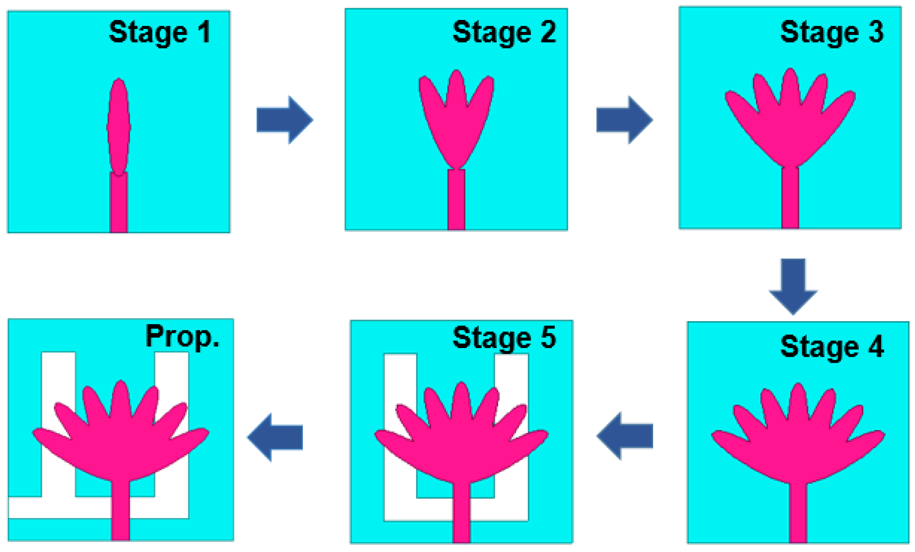
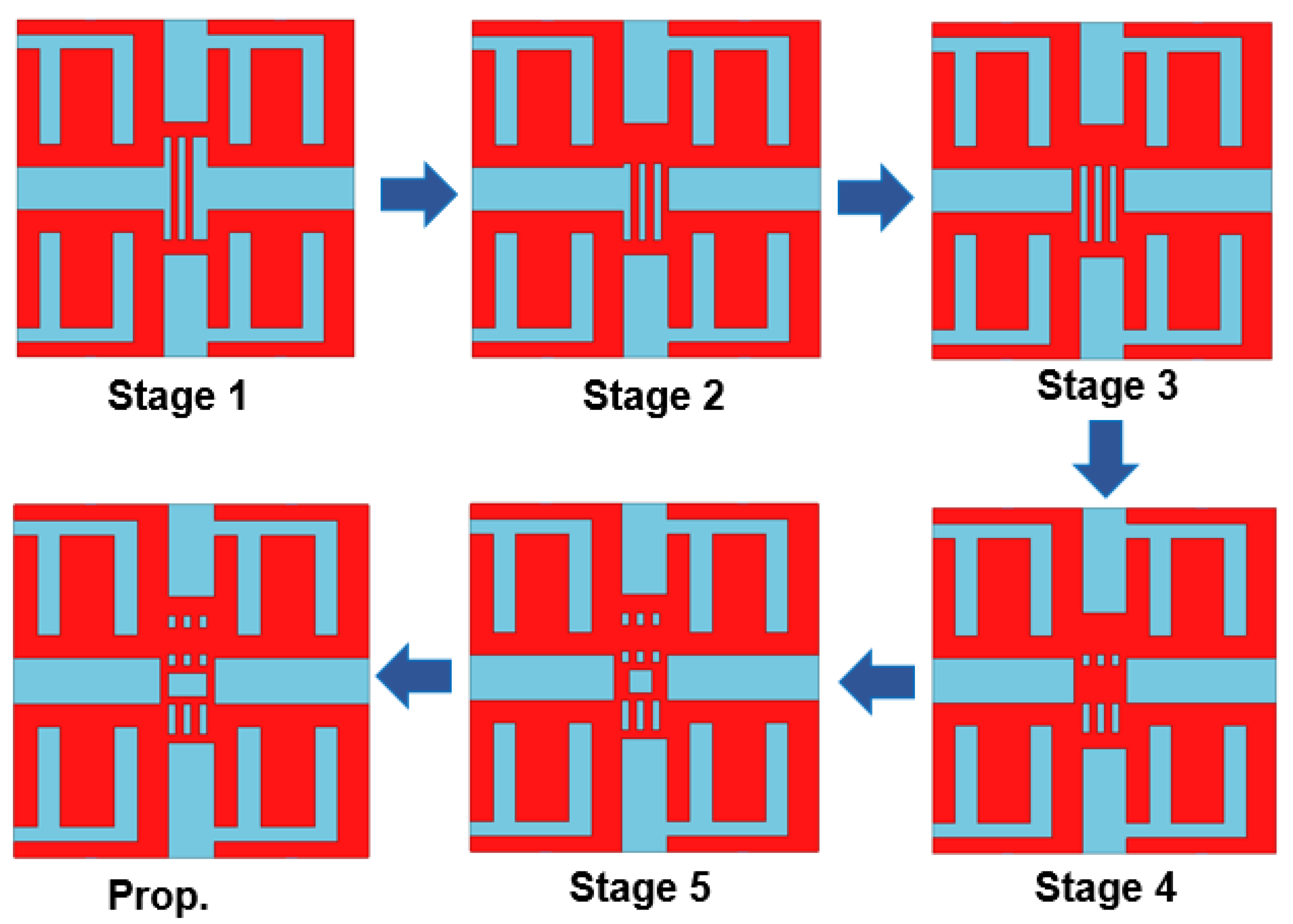
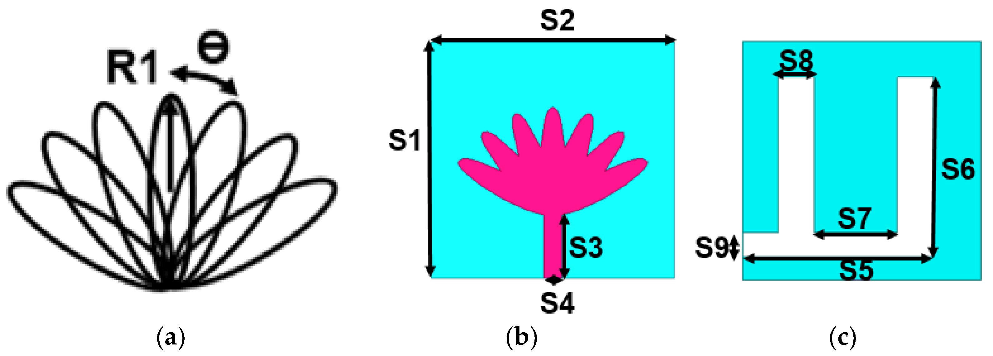
2. Quad-Port THz Antenna Design Methodology

Figure 1 depicts the overall evolutionary stages of the proposed antenna. In the first place, an elliptical monopole antenna is fed with a 50 Ω feedline of dimensions 5.36 × 1.5 µm2 constituting an elliptical patch with major and minor radii of 4.5 µm and 1 µm, respectively, on a 20 × 20 × 2µm3 polyamide substrate. The first stage sees the S11 curve drop below −5 dB, forming the basis for proceeding to the next stage. In the second stage, two identical elliptical patches are placed in a petal-like configuration. This stage witnesses the S11 curve drop twice below −5 dB. In the third stage, identical elliptical patches are similarly added on both sides, making the S11 curve drop below −15 dB. Proceeding onward, in this fashion, further elliptical patches are added on either side, as shown in stage 4. The S11 curve of stage 4 has a wide band, but it lies above −10 dB; to bring the drop below −10 dB, some rectangular patches are cut out from the ground plane, which can be seen in stage 5. The S11 curve finally drops below −10 dB with the rectangular patches cut out in a nearly ‘U-shaped’ configuration. But at this stage, the S11 curve can be seen to be at −10 dB at some intermediate frequency, so to bring it completely below −10 dB, i.e., to increase the bandwidth, stage 5 is further optimized to meet this requirement. Finally, the proposed antenna has a bandwidth of 8.96–13.5 THz with a uniform gain. The dimensions of the proposed antenna are presented in Figure 2. The scattering parameters of the individual stages of the antenna from stage 1 to stage 6 are depicted in Figure 3.
The designed THz antenna evolved based on a nature-inspired palmate leaf design. At the very first stage, a microstrip feedline was connected to the ellipse having a major radius (R1) of 4.5 µm with the full ground plane. The first stage was modified sequentially by incorporating more number ellipses onto the radiator by tilting (θ) each ellipse by 20 degrees. As seen in stage 4 of Figure 1, seven ellipses were merged to form a palmate leaf. The increase in the radiator’s circumference helps to move the impedance bandwidth toward the lower-frequency side, as the circumference is inversely proportional to the frequency. Further, the ground plane was modified by inserting a U-shaped slot to realize the desired wider impedance bandwidth, as depicted in stages 5–6 of Figure 1. The U-shaped slot in the ground plane changes the uniform current distribution by creating open- and closed-loop local current paths. The change in current on the ground plane influences the lumped components of the transmission line and decreases the quality factor. Modifying the radiator and ground plane helps realize a wider impedance bandwidth within the 8.96–13.5 THz frequency range.
Optimization was performed at stage 5 for the parameters S6 and S8 on the ground plane. The reflection coefficient graphs for each of the parameters are shown in Figure 4a,b. The parameter values were varied, while other dimensions on the ground plane were kept constant. The best S11 curve was finalized before optimizing the next parameter. In this way, the most optimal result was achieved, which can be seen in Figure 3. S6 was varied from 11 µm to 15 µm with a step size of 2 µm. The first two values of S6 showed a poor reflection coefficient, particularly in the frequency range of 10 to 12 THz. Therefore, an optimal S6 value of 15 µm was chosen. The width of the slot on the ground plane S8 significantly impacts the antenna’s operational frequency. The parameter S8 was varied from 2 µm to 4 µm with a step size of 1 µm. S8 values of 2 µm and 4 µm altered the corresponding impedance matching at 12–13 THz and 11–12 THz. Therefore, an S8 value of 3 µm was selected to realize a wider impedance bandwidth of 8.96–13.5 THz.
The lotus-shaped THz antenna was replicated horizontally into a two-element MIMO antenna with an interelement distance of less than λ/4, specifically, 0.18λ (6 µm). To keep the spacing between the two antenna elements at less than 6 µm, the spacing was initially taken to be 2 µm, and then a comprehensive parametric analysis was carried out. The interelement spacing was finalized at 6 µm. The overall dimensions of the proposed two-port THz antenna are shown in Figure 5a. The ground plane of both antenna elements was connected using a 6 × 2 µm2 rectangular strip, as shown in Figure 5b. The corresponding S11/S22 curve and S12/S21 curve were found to give satisfactory results, as can be seen in Figure 6a,b. The designed THz MIMO antenna has an impedance bandwidth of 8.96–13.3 THz. The isolation among the elements of the MIMO antenna is better than −29 dB throughout the antenna’s operating frequency. This improved isolation was achieved by adding parasitic elements as ground plane defects, as illustrated in Figure 5b.
The reflection and transmission coefficient curves for the finalized two-element MIMO are shown in Figure 6.
The two-element THz MIMO antenna was mirrored vertically, with a vertical spacing of 17 µm, to give the four-element MIMO configuration. The proposed four-port MIMO configuration and its dimensions are shown in Figure 7a,b. Similar to the two-element MIMO, the four-element MIMO should have a common ground plane. Figure 8 shows the elementary stages of connecting the ground planes of the individual elements. At each stage, the reflection coefficient and the transmission coefficient curves were analyzed.
The ground plane was modified at each stage to have a higher impedance bandwidth and improved isolation. The defective ground plane is composed of vertical and horizontal slots. These slots disrupt the uniform current flow in the ground plane, lowering the total coupling by generating a negative coupling field. The reflection and transmission coefficient curves for all the stages are shown in Figure 9a,b. In stage 1, two vertical rectangular strips connect the common ground planes of each of the two-element configurations situated on the upper and lower sides. The S11 characteristics plot for stage 1 has an impedance bandwidth of 2 THz and port isolation of more than −25 dB. In stage 2, an additional vertical rectangular strip was connected on the right side, and a horizontal rectangular strip was inserted between the upper edges. The s11 plot of stage 2 has a bandwidth slightly greater than 2 THz and similar isolation to that of stage 1. Stage 3 added a vertical rectangular strip on the left side. In stage 4, a horizontal rectangular strip was inserted in the center of the DGS. In stage 5, a small square strip was removed from the middle portion, the lower side of DGS was reduced while the upper side was enlarged, and three smaller square slots were inserted. The final stage of the proposed DGS has a rectangular slot rather than a square slot in the center. The dimensions associated with the final defected ground structure are shown in Figure 7b.
The rectangular slots made on the proposed ground plane enhanced the bandwidth from 2 THz to 4 THz in the 9–13 THz frequency range while simultaneously exhibiting port isolation of more than −25 dB. The surface current distributions for resonant frequencies of 9.5 THz, 10.6 THz, and 12.6 THz are shown in Figure 10a–c, respectively. This process was achieved by exciting one of the ports while terminating the other ports. The main focus was to reduce the effects of mutual coupling using the defected ground structure. The current distribution was seen on the excited antenna element and defected ground structure, thus improving isolation.

3. Results

The antenna performance analysis for the THz frequency spectrum was conducted using Ansys HFSS and CST software. The scattering parameters are described using reflection and transmission coefficient plots. The antenna radiation characteristics were studied by constructing radiation plots at resonant frequencies. Finally, the diversity performance was analyzed by examining the envelope correlation coefficient, diversity gain, mean effective gain, total active reflection coefficient, channel capacity loss, and multiplexing efficiency plots. All these performance parameters were analyzed to validate the proposed antenna’s performance in real-time systems. A comparison of the proposed antenna with various other antennas available in the literature was carried out to validate the efficacy of the proposed design.

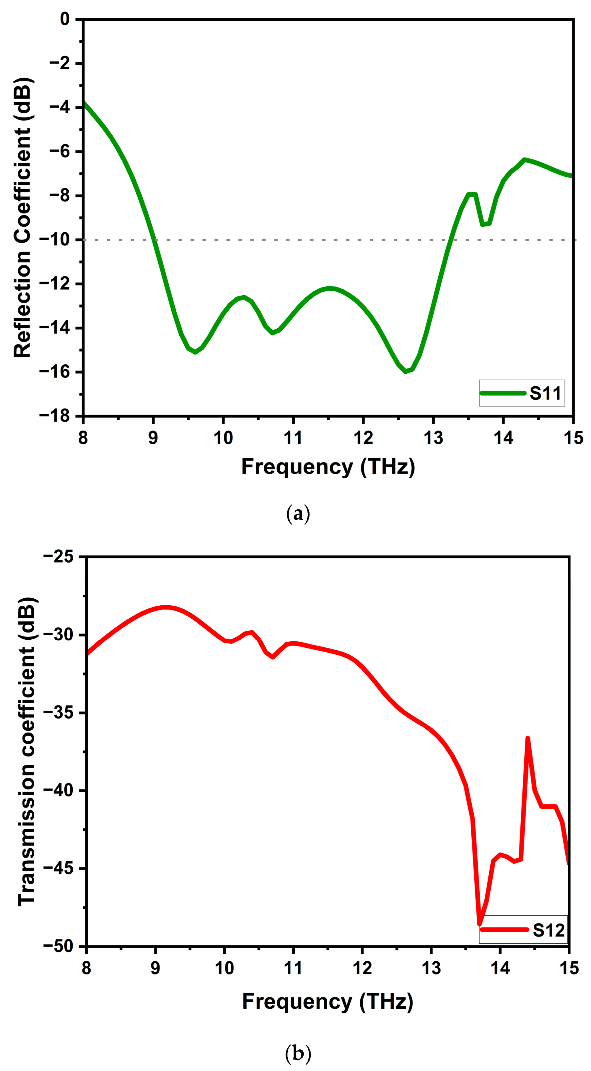
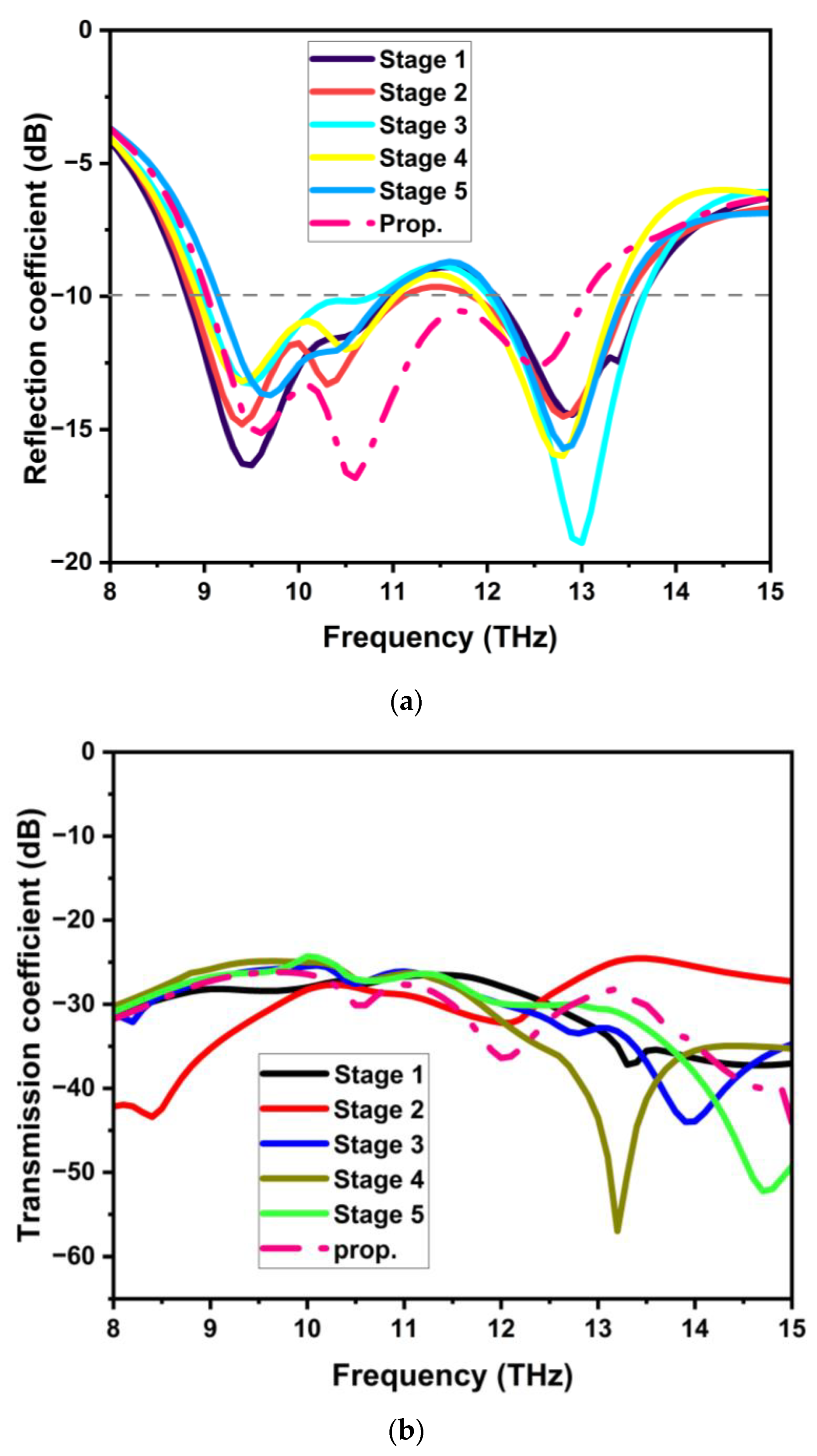
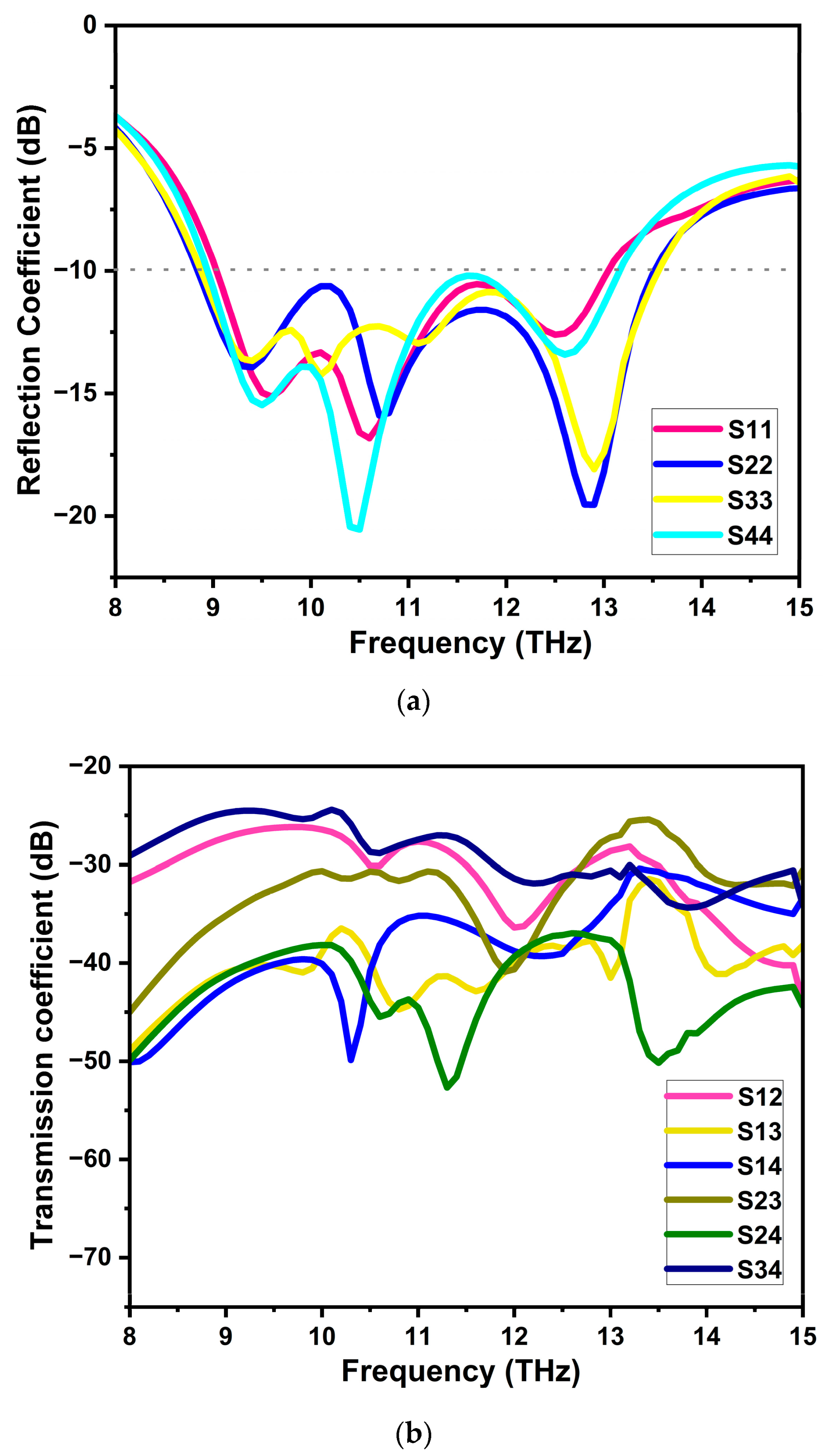
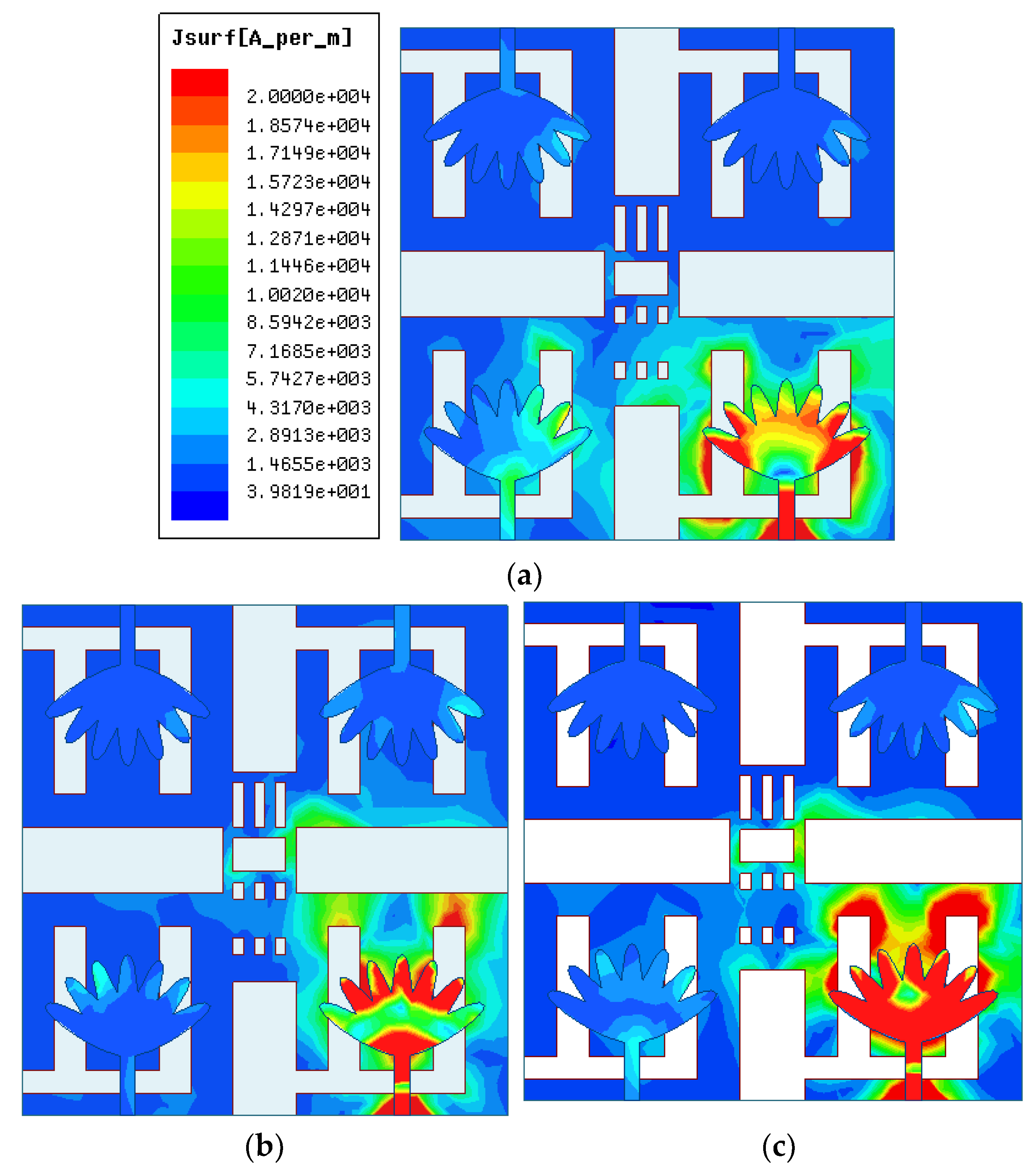
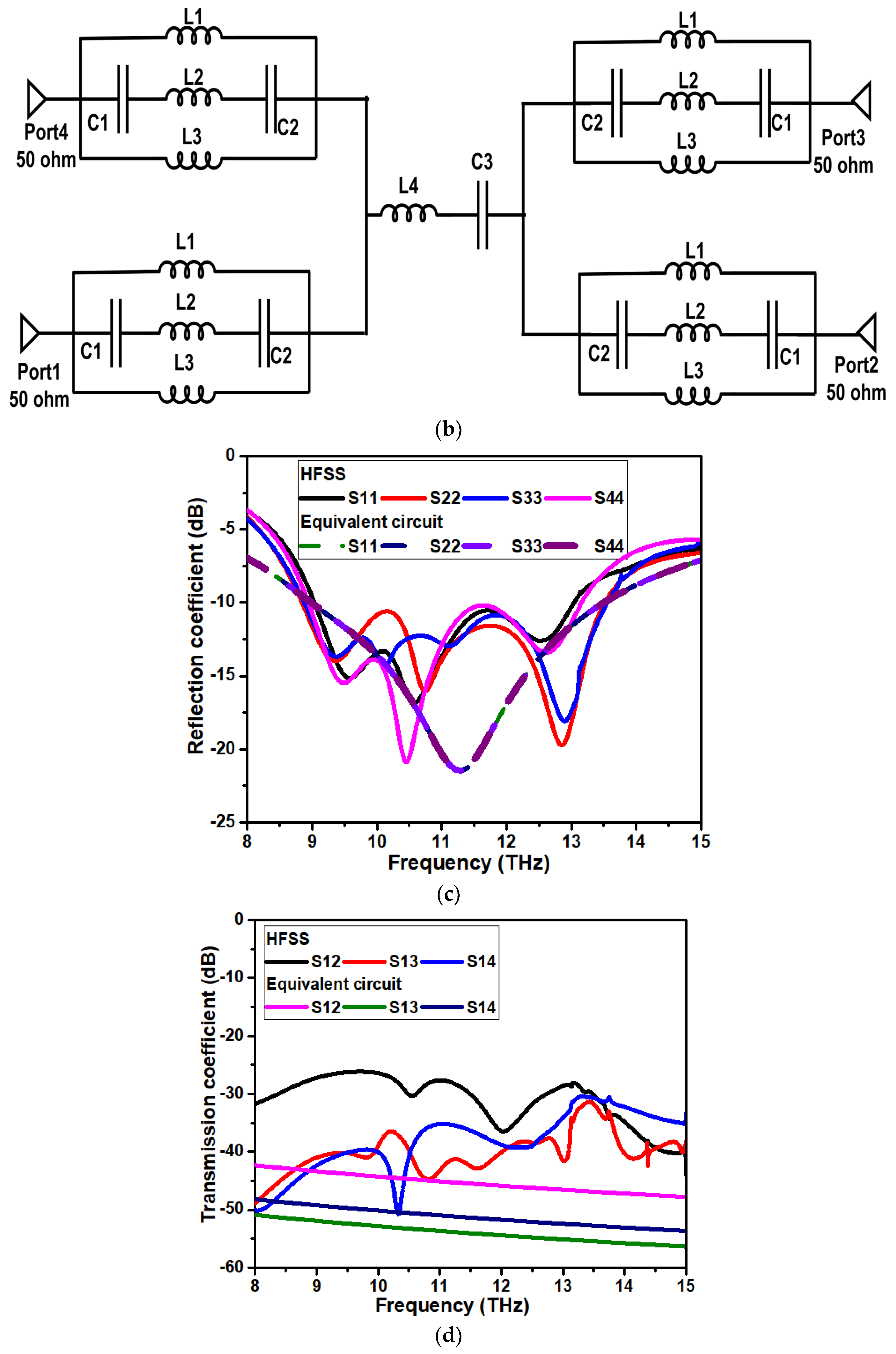
3.1. Scattering Parameters

The scattering parameters constitute the reflection and transmission coefficient curves. The reflection coefficient curve describes the ratio of the wave reflected due to the impedance mismatch of the medium to the incident wave in the medium. A reflection coefficient of more than −10 dB is desired for optimal performance. The transmission coefficient curve describes the ratio of transmitted waves upon encountering discontinuity in the medium, mostly due to the presence of elements adjacent to the incident wave. The transmission coefficient should ideally be more than −15 dB. The proposed MIMO antenna configuration was found to have a frequency ranging from 9 THz to 13 THz with a reflection coefficient below −10 dB, constituting the bandwidth and having resonant frequencies at 9.5, 10.6, and 12.6 THz. The transmission coefficient curve in this frequency range is below −25 dB. The reflection and transmission coefficient curves for the proposed four-element MIMO configuration are shown in Figure 11a,b, respectively.
The simulated S-parameters of the designed THz MIMO antenna were validated through an analogous lumped equivalent circuit. The circuit theory analysis and impedance method was used for constructing the equivalent circuit for the radiator and ground plane, as depicted in Figure 12a,b. The NIAWR software and tuning and optimization procedure was used to model the equivalent circuit. The values of antenna circuit components were predicted using the equations and model technique described in [47,48]. The single-element THz antenna’s equivalent circuit was designed initially and connected using coupling capacitors of the same circuit for other antennas. The antenna resonances were collectively modelled using series RLC parallel-fed components to synchronize the resonances in syntony since the antenna impedance represents real and imaginary components that have parallel resonances, which are constant in the wideband frequency of operation. The circuit was excited using 50 Ω ports, and responses were recorded in terms of reflected and transmission coefficients, as illustrated in Figure 11c,d. The wideband THz antennas were uniformly represented using lumped elements due to the symmetry in the MIMO antenna configuration.

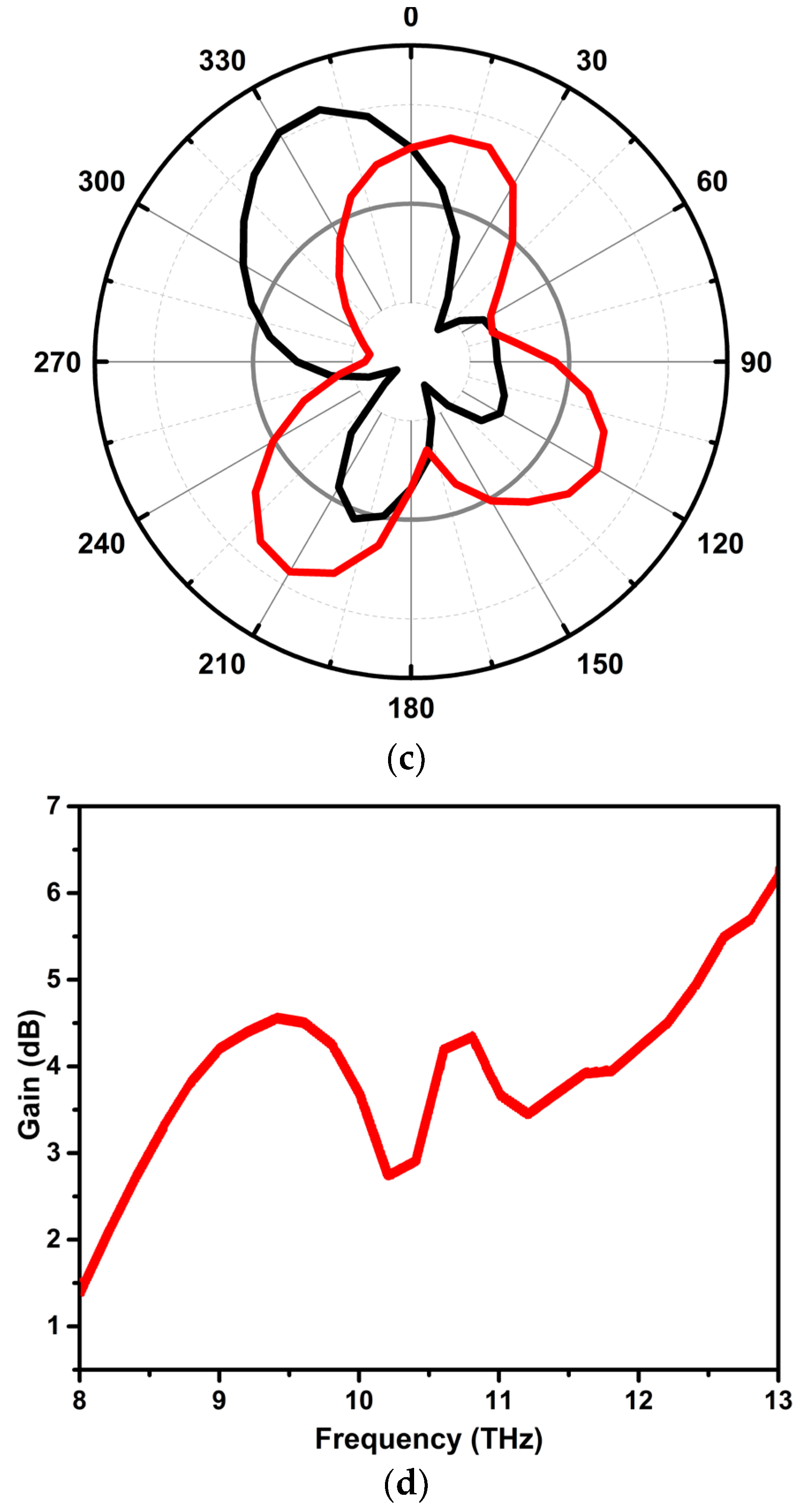
3.2. Radiation Characteristics

The radiation pattern of the antenna represents the energy radiated in space. The field patterns of radiation were plotted as a function of the E-field and H-field. The radiation plots for the resonant frequencies 9.5, 10.6, and 12.6 THz are shown in Figure 13 a–c respectively. The radiation patterns of the E-plane for resonant frequencies 9.5 THz, 10.6 THz, and 12.6 THz are approximately bidirectional and omnidirectional in the H-plane correspondingly. The proposed MIMO antenna has good results in terms of gain. The gain–frequency plot for the antenna is shown in Figure 13d. The maximum gain of 6.28 dB was witnessed at 13 THz, and the minimum gain of 2.773 dB was observed at 10.2 THz frequency.

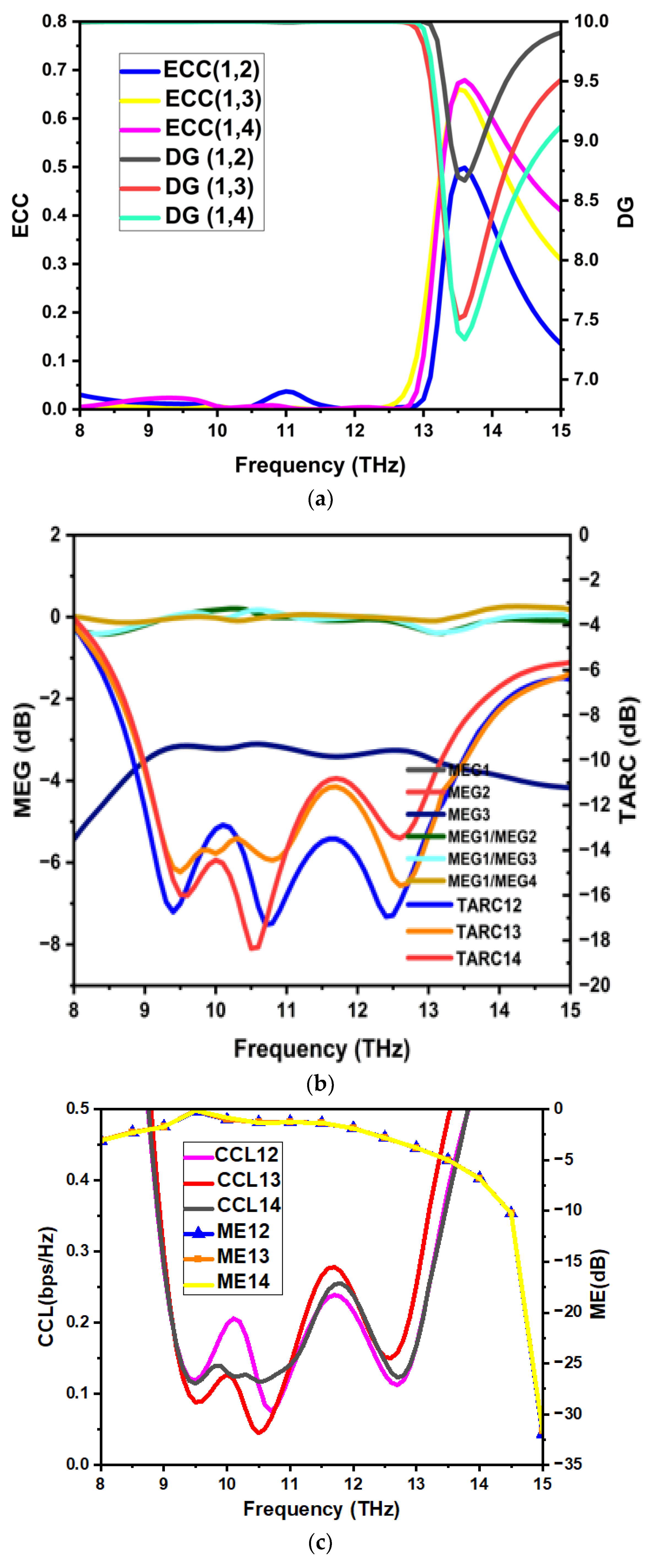
3.3. MIMO Diversity Characteristics

Diversity parameters were analyzed to study the performance of multiple antennas (MIMO) to reduce fading losses. The envelope correlation coefficient (ECC) is measured using far-field radiation patterns and scattering parameters. For optimal diversity performance, the ECC should be less than 0.5. The goal of the ECC is to evaluate the number of interactions among neighboring antenna elements in MIMO systems. Correlations across antenna elements weaken as the ECC decreases. The ECC of the antenna can be computed using Equation (1):
ECC = 0 2 π 0 π XPR · E θ i E θ j P θ + E ϕ i E ϕ j P ϕ 2 0 2 π 0 π XPR · E θ i E θ i P θ + E ϕ i E ϕ i P ϕ d Ω × 0 2 π 0 π XPR · E θ j E θ j P θ + E ϕ j E ϕ j P ϕ d Ω  
where XPR is the cross-polarization ratio, P θ and P ϕ are the incoming wave’s angular density functions in fields θ and ϕ, and E θ and E ϕ are the complex envelopes across the θ and ϕ components.
The diversity gain (DG) is calculated using ECC values. The DG value should be approximately 10. The mean effective gain (MEG) is the ratio of the mean power received by an antenna to that received by an isotropic antenna; it should be less than −3 dB, and the MEG ratio should be approximately 0. The total active reflection coefficient (TARC) measures the design effectiveness in terms of radiating power considering multiple antennas set up, and it should be less than −10 dB. The TARC is utilized to properly estimate the impedance matching of the MIMO antenna system. It is calculated as the square root of the total reflected power divided by incident power. The DG, MEG, and TARC are calculated using Equations (2)–(4).
DG = 10 1 ECC
MEG i = 0.5   η i , r a d = 0.5 1 j = 1 P S i j
Here, η i , r a d is the ith element’s radiation efficiency, P is the total number of elements present in the MIMO system, and S i j   is the s-parameter between ports i and j.
TARC = j = 1 4 S j 1 + m = 2 4 S j m e j θ m 1 2 4
Here, θ is the phase angle of the input feeding and S j m is the s-parameter between ports j and m, where j = 1, 2, 3, 4 and m = 2, 3, 4.
The channel capacity is enhanced with multiple elements, and the loss in the channel capacity (CCL) should be less than 0.4 bps/Hz. The number of antennas in any traditional MIMO system may be expanded to improve channel capacity. The CCL, on the other hand, is created by the correlation of densely positioned antenna components. The CCL is the upper limit rate of the channel for reliable communication. The multiplexing efficiency (ME) is the measure of effective element spacing in the MIMO configuration and should be less than 0 dB. The ME is a statistic used to assess the performance of a MIMO antenna system in spatial multiplexing mode, taking into account the efficiency and correlation among MIMO radiating elements. From the mathematical expressions for calculating the diversity parameters, Figure 14a–c shows the diversity plots of the above parameters. The simulated values of ECC and DG were less than 0.05, DG was approximately 10, MEG was less than −3 dB, the MEG ratio was approximately 0, TARC was less than −10 dB, CCL was less than 0.3 bps/Hz, and ME was less than 0 dB. These diversity parameter values prove that the values are well within the specified limits. The CCL and ME are computed using Equations (5) and (6).
CCL = l o g 2 det α R
Here, α R is the receiving antenna correlation matrix. For a four-element MIMO system, α R   is expressed as
α R = ρ 11 ρ 12 ρ 13 ρ 14 ρ 21 ρ 22 ρ 23 ρ 24 ρ 31 ρ 32 ρ 33 ρ 34 ρ 41 ρ 42 ρ 43 ρ 44
ρ i i = 1 n = 1 N S i n   S n i f o r   i , j = 1 , 2 , 3 , 4 ,
ρ i j = 1 n = 1 N S i n   S n j f o r   i , j = 1 , 2 , 3 , 4 ,
η m u x = η 1 η 2 1 ρ i j
where η 1 and η 2 are the radiation efficiencies of the first and second antenna elements.

3.4. Comparative Analysis

In the literature, many antennas and MIMO structures operating in the THz frequency spectrum have been developed with different design techniques, substrate types, dimensions, and antenna performance parameters. The comparative analysis of the proposed design structures with this existing work is presented in tabular form. The antenna characteristics, such as impedance bandwidth, isolation, and peak gain, are tabulated in Table 2, and MIMO diversity parameters are listed in Table 3. The proposed antenna outperforms those in [32,33,34,35,36,37] in terms of compactness, isolation, and gain. Also, the proposed antenna has good diversity parameters relative to the antenna designs presented in [32,33,34,35,36,37].

4. Conclusions

In this paper, we proposed a nature-inspired lotus-shaped radiating element for the THz frequency range. It was further developed into a four-port MIMO antenna with a unique defected ground structure to reduce mutual coupling. Various performance analyses included reflection and transmission coefficient plots, gain plots, radiation plots, surface current distribution, and diversity performance plots like ECC, DG, MEG, TARC, CCL, and ME. The reflection and transmission curve demonstrated a bandwidth of 9–13 THz and isolation better than −25 dB throughout the impedance bandwidth. Also, the antenna has approximately bidirectional and omnidirectional radiation properties at its resonant frequencies. Among the diversity parameters, ECC was less than 0.05, DG was approximately 10 dB, MEG was less than −3 dB, TARC was −10 dB, CCL was 0.3 bps/Hz, and ME was less than 0 dB. As a result, the suggested MIMO antenna has been validated for use in high-speed 6G wireless link communication networks.

Author Contributions

Conceptualization, J.R., P.K (Praveen Kumar)., T.A., P.S.B.G. and S.P.; methodology, J.R., P.K. (Praveen Kumar) and T.A.; software, J.R. and P.K. (Pradeep Kumar).; validation, T.A., P.S.B.G. and S.P.; writing—original draft preparation, J.R. and P.K. (Praveen Kumar); writing—review and editing, T.A., P.S.B.G., P.K. (Pradeep Kumar) and S.P.; supervision, T.A. All authors have read and agreed to the published version of the manuscript.

Funding

This research received no external funding.

Data Availability Statement

Data are contained within the article.

Conflicts of Interest

The authors declare no conflict of interest.

References

  1. Tripathi, S.; Sabu, N.V.; Gupta, A.K.; Dhillon, H.S. Millimeter-Wave and Terahertz Spectrum for 6G Wireless. In Computer Communications and Networks; Springer: Cham, Switzerland, 2021; pp. 83–121. [Google Scholar] [CrossRef]
  2. Attaran, M. The impact of 5G on the evolution of intelligent automation and industry digitization. J. Ambient. Intell. Humaniz. Comput. 2021, 14, 5977–5993. [Google Scholar] [CrossRef] [PubMed]
  3. Dangi, R.; Lalwani, P.; Choudhary, G.; You, I.; Pau, G. Study and Investigation on 5G Technology: A Systematic Review. Sensors 2021, 22, 26. [Google Scholar] [CrossRef] [PubMed]
  4. Singh, R.; Lehr, W.; Sicker, D.; Huq, K.M.S. Beyond 5G: The Role of THz Spectrum. In Proceedings of the 47th Research Conference on Communication, Information and Internet Policy, Washington, DC, USA, 19–21 September 2019. [Google Scholar] [CrossRef]
  5. Malhotra, I.; Jha, K.R.; Singh, G. Terahertz antenna technology for imaging applications: A technical review. Int. J. Microw. Wirel. Technol. 2018, 10, 271–290. [Google Scholar] [CrossRef]
  6. Huang, Y.; Shen, Y.; Wang, J. From Terahertz Imaging to Terahertz Wireless Communications. Engineering 2023, 22, 106–124. [Google Scholar] [CrossRef]
  7. Petrov, V.; Pyattaev, A.; Moltchanov, D.; Koucheryavy, Y. Terahertz band communications: Applications, research challenges, and standardization activities. In Proceedings of the 2016 8th International Congress on Ultra Modern Telecommunications and Control Systems and Workshops (ICUMT), Lisbon, Portugal, 18–20 October 2016; pp. 183–190. [Google Scholar] [CrossRef]
  8. Jamshed, M.A.; Nauman, A.; Abbasi, M.A.B.; Kim, S.W. Antenna Selection and Designing for THz Applications: Suitability and Performance Evaluation: A Survey. IEEE Access 2020, 8, 113246–113261. [Google Scholar] [CrossRef]
  9. Chen, S.; Liang, Y.-C.; Sun, S.; Kang, S.; Cheng, W.; Peng, M. Vision, Requirements, and Technology Trend of 6G: How to Tackle the Challenges of System Coverage, Capacity, User Data-Rate and Movement Speed. IEEE Wirel. Commun. 2020, 27, 218–228. [Google Scholar] [CrossRef]
  10. Wallace, J.; Jensen, M. Mutual coupling in MIMO wireless systems: A rigorous network theory analysis. IEEE Trans. Wirel. Commun. 2004, 3, 1317–1325. [Google Scholar] [CrossRef]
  11. Malathi, A.C.J.; Thiripurasundari, D. Review on Isolation Techniques in MIMO Antenna Systems. Indian J. Sci. Technol. 2016, 9, 1–10. [Google Scholar] [CrossRef]
  12. Khalid, M.; Naqvi, S.I.; Hussain, N.; Rahman, M.; Fawad; Mirjavadi, S.S.; Khan, M.J.; Amin, Y. 4-port MIMO antenna with defected ground structure for 5G millimeter wave applications. Electronics 2020, 9, 71. [Google Scholar] [CrossRef]
  13. Jilani, S.F.; Alomainy, A. Millimetre-wave T-shaped MIMO antenna with defected ground structures for 5G cellular networks. IET Microw. Antennas Propag. 2018, 12, 672–677. [Google Scholar] [CrossRef]
  14. Xing, H.; Wang, X.; Gao, Z.; An, X.; Zheng, H.-X.; Wang, M.; Li, E. Efficient isolation of an mimo antenna using defected ground structure. Electronics 2020, 9, 1265. [Google Scholar] [CrossRef]
  15. Babu, K.V.; Anuradha, B. Design of UWB MIMO Antenna to Reduce the Mutual Coupling Using Defected Ground Structure. Wirel. Pers. Commun. 2021, 118, 3469–3484. [Google Scholar] [CrossRef]
  16. Li, Z.; Du, Z.; Takahashi, M.; Saito, K.; Ito, K. Reducing mutual coupling of MIMO antennas with parasitic elements for mobile terminals. IEEE Trans. Antennas Propag. 2011, 60, 473–481. [Google Scholar] [CrossRef]
  17. Karimian, R.; Tadayon, H. Multiband MIMO antenna system with parasitic elements for WLAN and WiMAX application. Int. J. Antennas Propag. 2013, 2013, 365719. [Google Scholar] [CrossRef]
  18. Bulu, I.; Caglayan, H. Designing Materials With Desired. Microw. Opt. 2006, 48, 2611–2615. [Google Scholar] [CrossRef]
  19. Tiwari, R.N.; Singh, P.; Kanaujia, B.K.; Srivastava, K. Neutralization technique based two and four port high isolation MIMO antennas for UWB communication. AEU-Int. J. Electron. Commun. 2019, 110, 152828. [Google Scholar] [CrossRef]
  20. Liu, R.; An, X.; Zheng, H.; Wang, M.; Gao, Z.; Li, E. Neutralization Line Decoupling Tri-Band Multiple-Input Multiple-Output Antenna Design. IEEE Access 2020, 8, 27018–27026. [Google Scholar] [CrossRef]
  21. Kumar, P.; Ali, T.; Mm, M.P. Characteristic Mode Analysis-Based Compact Dual Band-Notched UWB MIMO Antenna Loaded with Neutralization Line. Micromachines 2022, 13, 1599. [Google Scholar] [CrossRef]
  22. Sakli, H.; Abdelhamid, C.; Essid, C.; Sakli, N. Metamaterial-Based Antenna Performance Enhancement for MIMO System Applications. IEEE Access 2021, 9, 38546–38556. [Google Scholar] [CrossRef]
  23. Chen, L.; Ma, Q.; Luo, S.S.; Ye, F.J.; Cui, H.Y.; Cui, T.J. Touch-Programmable Metasurface for Various Electromagnetic Manipulations and Encryptions. Small 2022, 18, 2203871. [Google Scholar] [CrossRef]
  24. Zhai, G.; Chen, Z.N.; Qing, X. Enhanced isolation of a closely spaced four-element MIMO antenna system using metamaterial mushroom. IEEE Trans. Antennas Propag. 2015, 63, 3362–3370. [Google Scholar] [CrossRef]
  25. Lee, Y.; Ga, D.; Choi, J. Design of a MIMO antenna with improved isolation using MNG metamaterial. Int. J. Antennas Propag. 2012, 2012, 864306. [Google Scholar] [CrossRef]
  26. Gurjar, R.; Upadhyay, D.K.; Kanaujia, B.K.; Kumar, A. A compact modified sierpinski carpet fractal UWB MIMO antenna with square-shaped funnel-like ground stub. AEU-Int. J. Electron. Commun. 2020, 117, 153126. [Google Scholar] [CrossRef]
  27. Mohanty, A.; Sahu, S. High isolation two-port compact MIMO fractal antenna with Wi-Max and X-band suppression characteristics. Int. J. RF Microw. Comput. Eng. 2019, 30, e22021. [Google Scholar] [CrossRef]
  28. Tripathi, S.; Mohan, A.; Yadav, S. A Compact Koch Fractal UWB MIMO Antenna With WLAN Band-Rejection. IEEE Antennas Wirel. Propag. Lett. 2015, 14, 1565–1568. [Google Scholar] [CrossRef]
  29. Chouhan, S.; Panda, D.K.; Kushwah, V.S.; Singhal, S. Spider-shaped fractal MIMO antenna for WLAN/WiMAX/Wi-Fi/Bluetooth/C-band applications. AEU-Int. J. Electron. Commun. 2019, 110, 152871. [Google Scholar] [CrossRef]
  30. Sree, G.N.J.; Nelaturi, S. Design and experimental verification of fractal based MIMO antenna for lower sub 6-GHz 5G applications. AEU-Int. J. Electron. Commun. 2021, 137, 153797. [Google Scholar] [CrossRef]
  31. Singhal, S. Four arm windmill shaped superwideband terahertz MIMO fractal antenna. Optik 2020, 219, 165093. [Google Scholar] [CrossRef]
  32. Babu, K.V.; Das, S.; Varshney, G.; Sree, G.N.J.; Madhav, B.T.P. A micro-scaled graphene-based tree-shaped wideband printed MIMO antenna for terahertz applications. J. Comput. Electron. 2022, 21, 289–303. [Google Scholar] [CrossRef]
  33. Sharma, M.K.; Sharma, A. Compact size easily extendable self isolated multi-port multi-band antenna for future 5G high band and sub-THz band applications. Opt. Quantum Electron. 2022, 55, 146. [Google Scholar] [CrossRef]
  34. Das, S.; Mitra, D.; Chaudhuri, S.R.B. Fractal Loaded Planar Super Wide Band MIMO Antenna in THz Frequency Range. In Proceedings of the 2020 IEEE Asia-Pacific Microwave Conference (APMC), Hong Kong, China, 8–11 December 2020; pp. 703–705. [Google Scholar] [CrossRef]
  35. Pandey, G.K.; Rao, T.; Mondal, S. Design and Analysis of Graphene based Octagonal Short-angular Circular Patch MIMO Antenna for Terahertz Communications. In Proceedings of the 2022 2nd International Conference on Intelligent Technologies (CONIT), Hubli, India, 24–26 June 2022; pp. 42–45. [Google Scholar] [CrossRef]
  36. Yadav, R.; Parmar, A.; Malviya, L.; Nitnaware, D. Ultra Wideband MIMO Antenna Design with High Isolation for THz Application. In Proceedings of the 2022 IEEE 11th International Conference on Communication Systems and Network Technologies (CSNT), Indore, India, 23–24 April 2022; pp. 26–30. [Google Scholar] [CrossRef]
  37. Mohanty, A.; Sahu, S. A Micro 4-port THz MIMO antenna for nano communication networks. Photon. Nanostructures—Fundam. Appl. 2023, 53, 101092. [Google Scholar] [CrossRef]
  38. Soltanmohammadi, H.; Jarchi, S.; Soltanmohammadi, A. Tunable dielectric resonator antenna with circular polarization and wide bandwidth for terahertz applications. Optik 2023, 287, 171124. [Google Scholar] [CrossRef]
  39. Varshney, G.; Gotra, S.; Kaur, J.; Pandey, V.S.; Yaduvanshi, R.S. Obtaining the circular polarization in a nano-dielectric resonator antenna for photonics applications. Semicond. Sci. Technol. 2019, 34, 07LT01. [Google Scholar] [CrossRef]
  40. Gupta, R.; Varshney, G.; Yaduvanshi, R. Tunable terahertz circularly polarized dielectric resonator antenna. Optik 2021, 239, 166800. [Google Scholar] [CrossRef]
  41. Chashmi, M.J.; Rezaei, P.; Kiani, N. Y-shaped graphene-based antenna with switchable circular polarization. Optik 2020, 200, 163321. [Google Scholar] [CrossRef]
  42. Kiani, N.; Hamedani, F.T.; Rezaei, P.; Chashmi, M.J.; Danaie, M. Polarization controling approach in recon-figurable microstrip graphene-based antenna. Optik 2020, 203, 163942. [Google Scholar] [CrossRef]
  43. Gotra, S.; Pandey, V.; Yaduvanshi, R. A wideband graphene coated dielectric resonator antenna with circular polarization generation technique for THz applications. Superlattices Microstruct. 2021, 150, 106754. [Google Scholar] [CrossRef]
  44. Vishwanath; Varshney, G.; Sahana, B.C. Implementing the single/multiport tunable terahertz circularly polarized dielectric resonator antenna. Nano Commun. Netw. 2022, 32, 100408. [Google Scholar] [CrossRef]
  45. Aqlan, B.; Himdi, M.; Vettikalladi, H.; Le-Coq, L. A circularly polarized sub-terahertz antenna with low-profile and high-gain for 6G wireless communication systems. IEEE Access 2021, 9, 122607–122617. [Google Scholar] [CrossRef]
  46. Ahmad, I.; Ullah, S.; Ullah, S.; Habib, U.; Ahmad, S.; Ghaffar, A.; Alibakhshikenari, M.; Khan, S.; Limiti, E. Design and analysis of a photonic crystal based planar antenna for THz applications. Electronics 2021, 10, 1941. [Google Scholar] [CrossRef]
  47. Singh, R.; Varshney, G. Isolation enhancement technique in a dual-band THz MIMO antenna with single radiator. Opt. Quantum Electron. 2023, 55, 539. [Google Scholar] [CrossRef]
  48. Kumar, P.M.M.M.P.; Kumar, P.; Ali, T.; Alsath, M.G.N.; Suresh, V. Characteristics Mode Analysis-Inspired Compact UWB Antenna with WLAN and X-Band Notch Features for Wireless Applications. J. Sens. Actuator Netw. 2023, 12, 37. [Google Scholar] [CrossRef]
Figure 1. Evolution of the proposed THz antenna.
Jsan 12 00069 g001
Figure 2. Proposed THz antenna (a) radiator evolution, (b) radiator plane, and (c) ground plane. Dimensions (in µm): R1 = 4.5, θ = 20 degrees, S1 = 20, S2 = 20, S3 = 5.36, S4 = 1.5, S5 = 16, S6 = 15, S7 = 7, S8 = 3, S9 = 2.
Jsan 12 00069 g002
Figure 3. Reflection coefficients for the evolutionary stages of the proposed THz antenna.
Jsan 12 00069 g003
Figure 4. Reflection coefficient graphs for optimization performed for parameters (a) S6 and (b) S8 on the ground plane of the proposed antenna (dimensions in µm).
Jsan 12 00069 g004
Figure 5. Two-element MIMO configuration: (a) radiator plane; (b) ground plane. Dimensions (in µm): P1 = 20, P2 = 46, P3 = 6, P4 = 6, P5 = 2.
Jsan 12 00069 g005
Figure 6. S-parameters of the two-port antenna: (a) reflection and (b) transmission coefficient curves.
Jsan 12 00069 g006
Figure 7. Four-element MIMO configuration: (a) radiator plane; (b) ground plane. Dimensions (in µm): M1 = 46, M2 = 46, M3 = 6, M4 = 17, M5 = 19, M6 = 7, M7 = 1, M8 = 3.5, M9 = 3, M10 = 5, M11 = 4.
Jsan 12 00069 g007
Figure 8. Evolutionary stages of the defective ground plane for the proposed four-element MIMO configuration.
Jsan 12 00069 g008
Figure 9. S-parameters of the evolutionary stages of the DGS: (a) reflection and (b) transmission coefficients.
Jsan 12 00069 g009
Figure 10. Current distribution for resonant frequencies of (a) 9.5 THz, (b) 10.6 THz, and (c) 12.6 THz.
Jsan 12 00069 g010
Figure 11. S-parameters of the proposed quad-port THz antenna: (a) reflection and (b) transmission coefficient curves.
Jsan 12 00069 g011
Figure 12. Validation of the THz MIMO antenna’s performance using analogous lumped circuit resistors (Ω), inductors (nH), and capacitors (pF). (a) Equivalent circuit radiator: R1 = 0.04, R2 = 7.04, R3 = 158, R4 = 0.22, R5 = 29.4, R6 = 1, L1 = 1.839, L2 = 8.85 × 10³ L3 = 7.6 × 10³, L4 = 0.5, L5 = 0.002, L6 = 6, C1 = 8.1 × 10³, C2 = 0.043, C3 = 3.8 × 10 5 , C4 = 0.017, C5 = 1.4 × 10 5 , C6 = 0.32, C7= 0.007, C8 = 0.0004, C9 = 0.007, C10 = 0.008. (b) Equivalent circuit ground plane: C1 = 0.633, C2 = 0.01, C3 = 0.06, L1 = 0.1, L2 = 0.11, L3 = 0.1 × 10 5 , L4 = 0.004. (c) Reflection coefficient and (d) transmission coefficient curves.
Jsan 12 00069 g012aJsan 12 00069 g012b
Figure 13. Radiation pattern at resonant frequencies of (a) 9.5 THz, (b) 10.6 THz, (c) and 12.6 THz; (d) gain vs. frequency plot.
Jsan 12 00069 g013aJsan 12 00069 g013b
Figure 14. MIMO diversity parameters (a) ECC and DG, (b) MEG/MEG ratio and TARC, (c) CCL and ME.
Jsan 12 00069 g014
Table 1. Comparison of the proposed terahertz antenna with its counterparts.
RefDesign TechniqueAntenna Size (µm2)Frequency Range (THz)Radiation Pattern (dB)Peak Gain (dB)Complexity
[38]Modified cross-slot110 × 1102.7–4.46Omnidirectional8.5Moderate
[39]λ/4-length path600 × 300187–210Omnidirectional4Simple
[40]Silicon slab150 × 200 × 803.96–4.1Directional6Complex
[41]Y-shaped graphene60 × 1100.42–0.48Omnidirectional0.12Complex
[42]Graphene patch200 × 2000.65–0.70Omnidirectional4.38Complex
[43]Graphene coating133 × 2557.76–12.51Omnidirectional8.15Complex
[44]Metal loading on the wall of a dielectric resonator48 × 444.27–4.86Bidirectional6.5Complex
[45]Fabry–Pérot cavity206 × 206281–305Omnidirectional7.5Complex
[46]Photonic-band-gap-based unit cells loaded with circular-shaped metallic insertion700 × 6600.61–0.64Bidirectional8.96Complex
Prop.Lotus-shaped radiator with DGS46 × 46 × 28.96–13.5Bidirectional8.96Simple
Table 2. Comparison of scattering parameters.
RefSub. TypeConductor TypeAntenna Size (µm3)N ElementsImpedance Bandwidth (THz)Isolation (dB)Peak Gain (dB)
[31]-copper110 × 65 × 1023.1–60>3012 dB
[32]polyimidegraphene600 × 300 × 4520.276–0.711>20-
[33]RT/duroid
5880
-150 × 200 × 802,4,80.024, 0.028
0.037, 0.035,
0.2
>30-
[34]polyimidecopper110 × 40 × 2020.8–10>208.6 dBi
[35]Si3N4graphene
and gold
378 × 354 × 1520.259–0.324>506.38 dBi
[36]polyimidegraphene,
alumina, and
silicon
133 × 25525.5–10>209.14 dBi
[37]polyamidecopper45 × 45 × 242.38–11.18>186.5 dBi
Prop.polyamidecopper46 × 46 × 22,48.96–13.5>258.96 dB
Table 3. Comparison of diversity parameters.
RefECCDG (dB)MEG (dB)TARC (dB)CCL (bps/Hz)ME (dB)
[31]<0.00001---<0.1-
[32]<0.00110<−3<−10<0.5-
[33]<0.000046---<0.023-
[34]<0.001>9.995----
[35]------
[36]---<0<0.2-
[37]<0.18>9.4<−3<−5 dB<0.3<−1.5
Prop.<0.0510<−3<−10<0.3<0
Disclaimer/Publisher’s Note: The statements, opinions and data contained in all publications are solely those of the individual author(s) and contributor(s) and not of MDPI and/or the editor(s). MDPI and/or the editor(s) disclaim responsibility for any injury to people or property resulting from any ideas, methods, instructions or products referred to in the content.

