IETF Standardization in the Field of the Internet of Things (IoT): A Survey

 ,
,  and
and
Abstract
:
1. Introduction
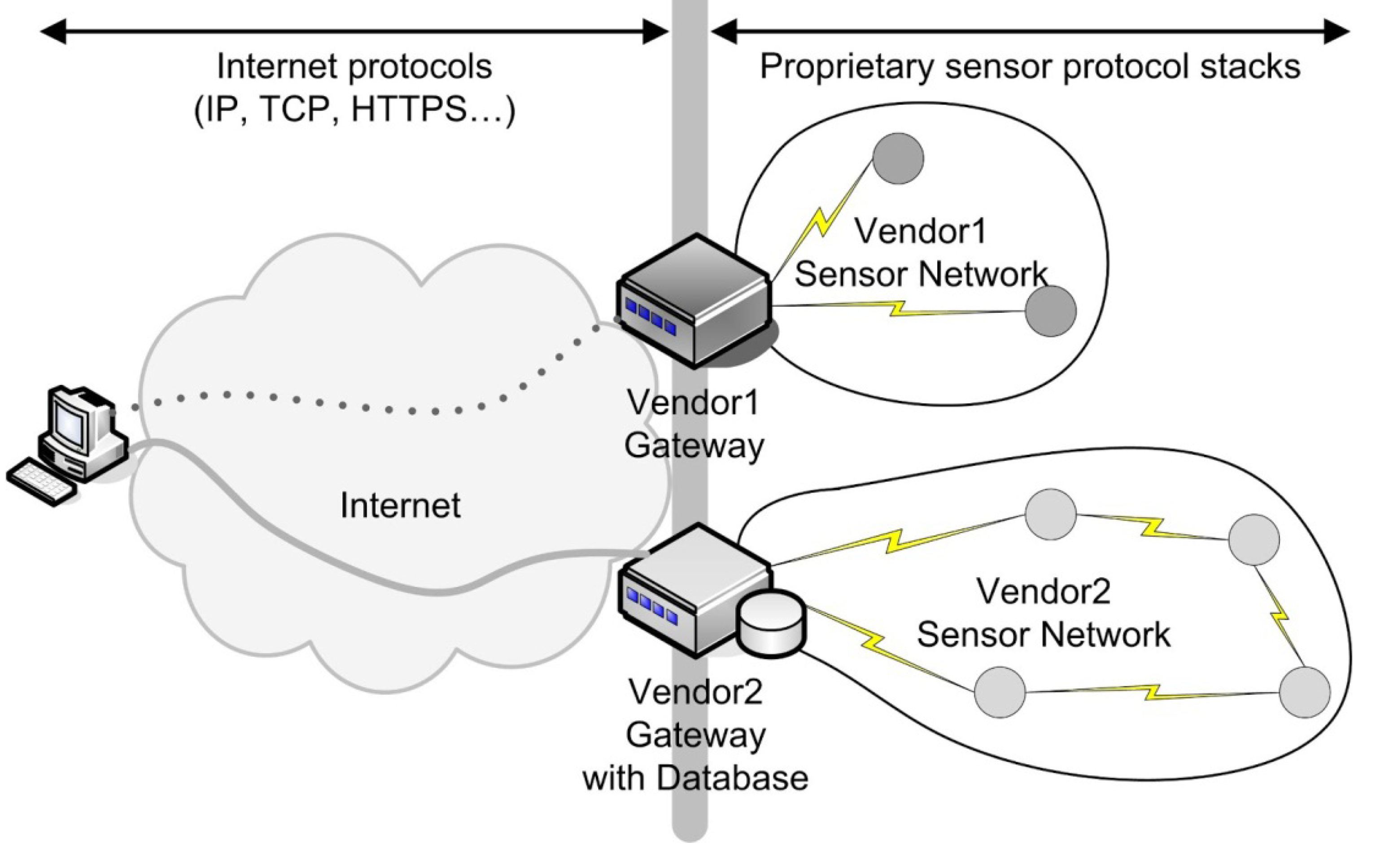
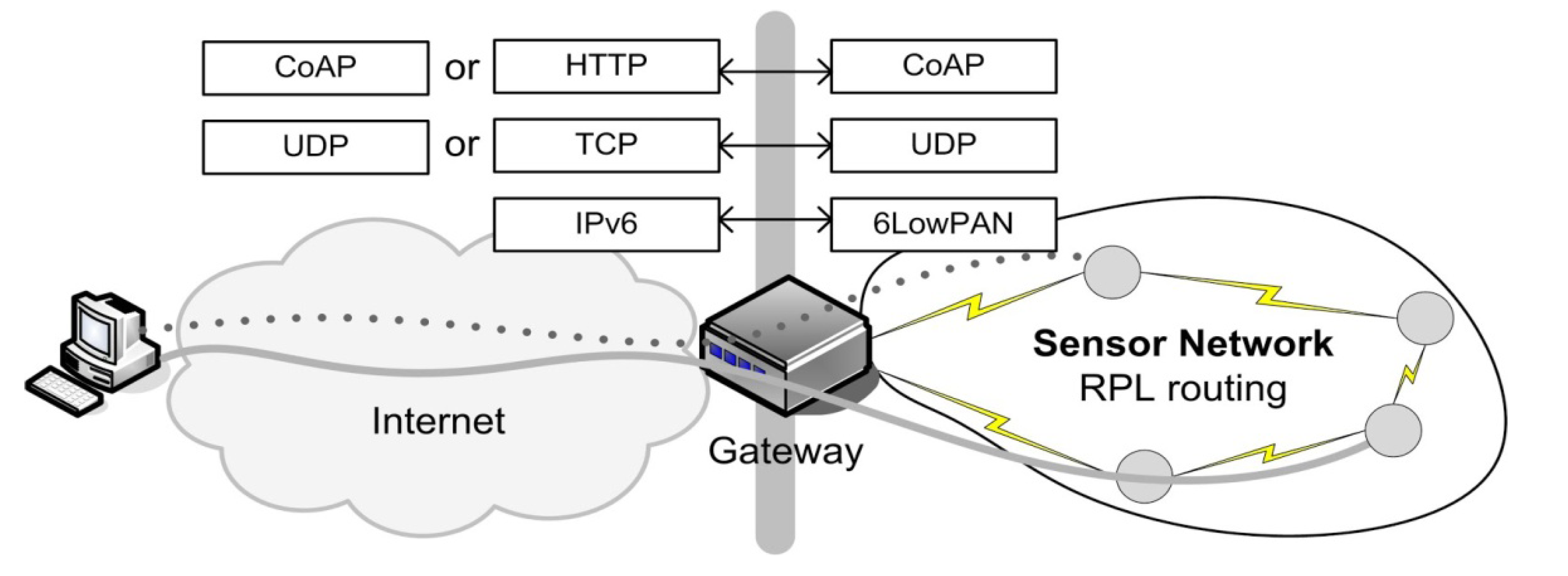
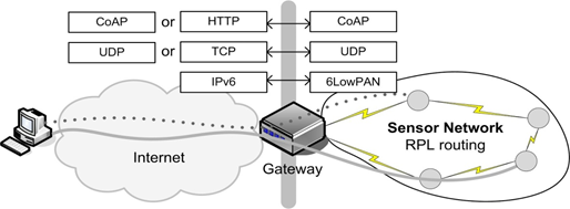
2. Integration of Constrained Devices into the Internet
3. IEEE 802.15.4
3.1. Physical Layer
3.2. MAC Sublayer
3.3. IEEE 802.15.4 Based Solutions
- ZigBee [10] builds upon the physical layer and medium access control defined in IEEE standard 802.15.4 for low-rate WPAN with additional network, security and application software layers. Predefined application services specify which actions a device can take, the main example being ”turn the lights on“ and ”turn the lights off”.
- Wireless HART [11] focuses on automation and industrial applications that require real time guarantees. To realize these goals, a time synchronized, self-organizing, and self-healing mesh architecture is used. The standard was initiated in early 2004 and developed by 37 HART Communications Foundation (HCF) companies. In April 2010, WirelessHart was approved by the International Electrotechnical Commission (IEC) unanimously, making it a wireless international standard as IEC 62591.
- The MiWi protocol stacks [12] are small foot-print alternatives to ZigBee (40K–100K), which makes them useful for cost-sensitive applications with limited memory. Although the MiWi software is free, there exists a unique restriction and obligation to use it only with Microchip microcontrollers.
- ISA100 [13] addresses wireless manufacturing and control systems (developed by the Systems and Automation Society (ISA)). They defined ISA100.11a, a wireless networking standard that builds upon IEEE 802.15.4.
4. IETF 6LoWPAN Working Group (IPv6)
4.1. Key Protocols
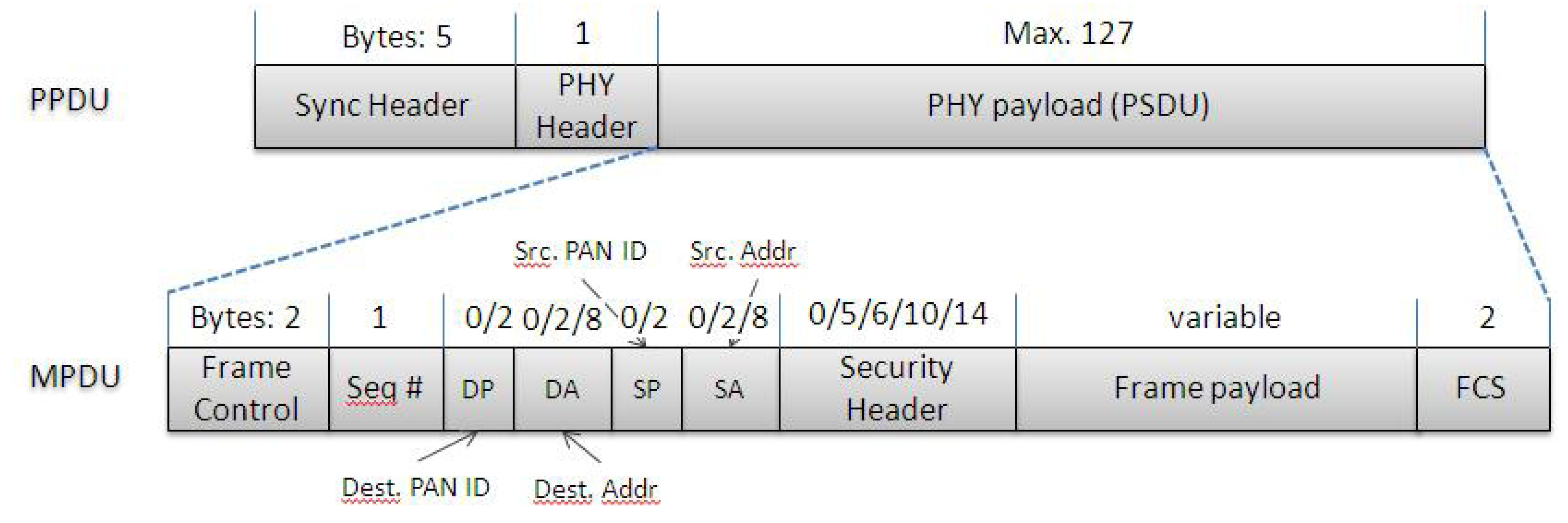
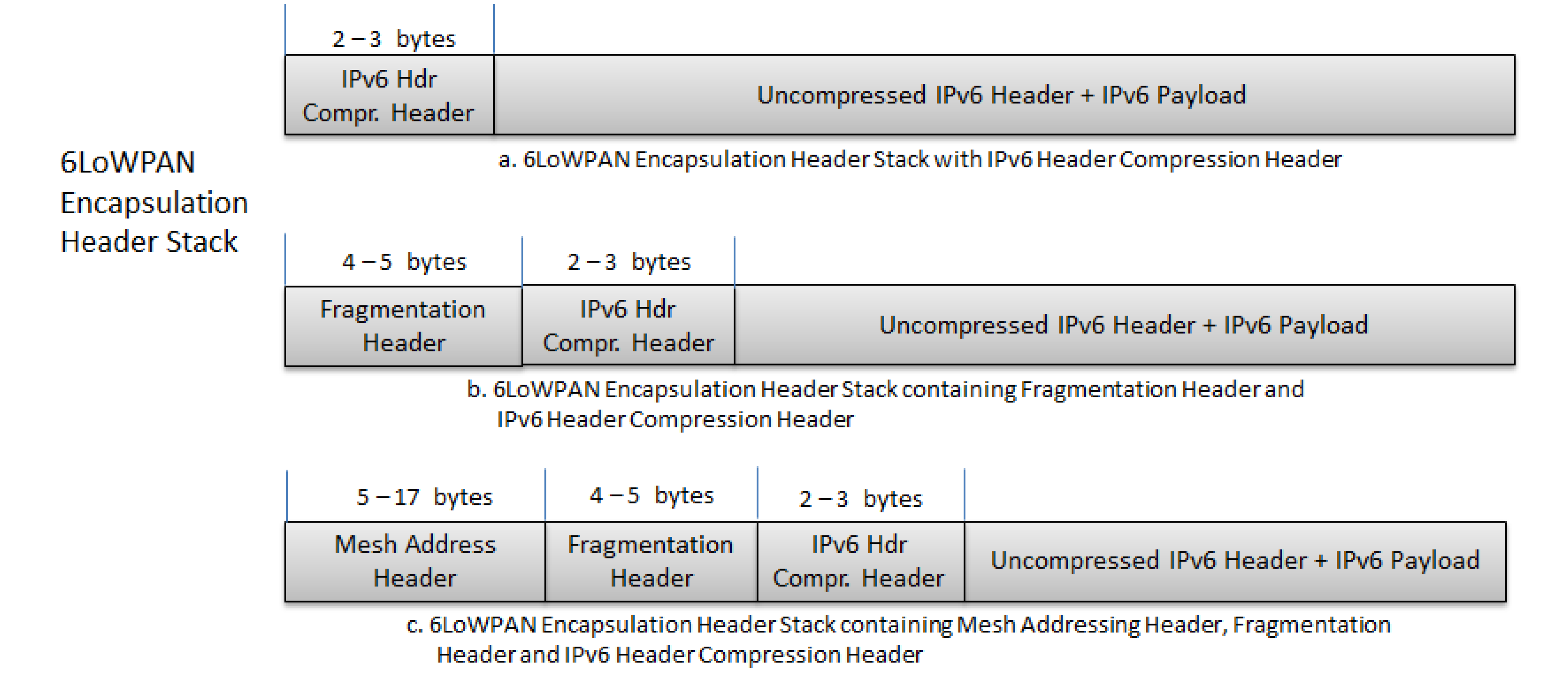
4.1.1. 6LoWPAN Frames


| First 3 Bits | Header Type | Description |
|---|---|---|
| 00x | NLAP | This is not a 6LoWPAN frame. This is important for 6LoWPAN to co-exist with other protocols. The remaining 6 bits are ignored. |
| 010 | Uncompressed/HC1 Compressed IPv6 Addressing Header | The address type is determined depending on the remaining 5 bits. E.g.: 00001 = uncompressed IPv6 Address 00010 = HC1 Compressed Header |
| 011 | IPHC Compressed Header | The remaining 5 bits are added to the rest of IPHC compression header to optimize IPv6 header compression |
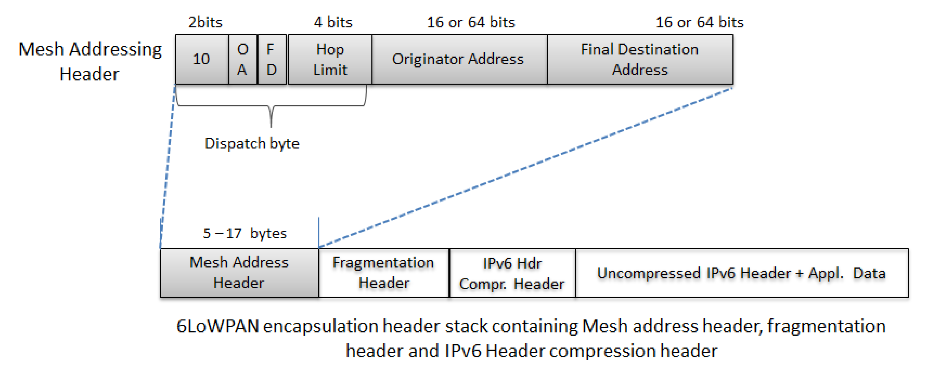
| 10x | Mesh Header | The next header is the mesh header. The last bits are used for other purposes related to mesh-under routing. |
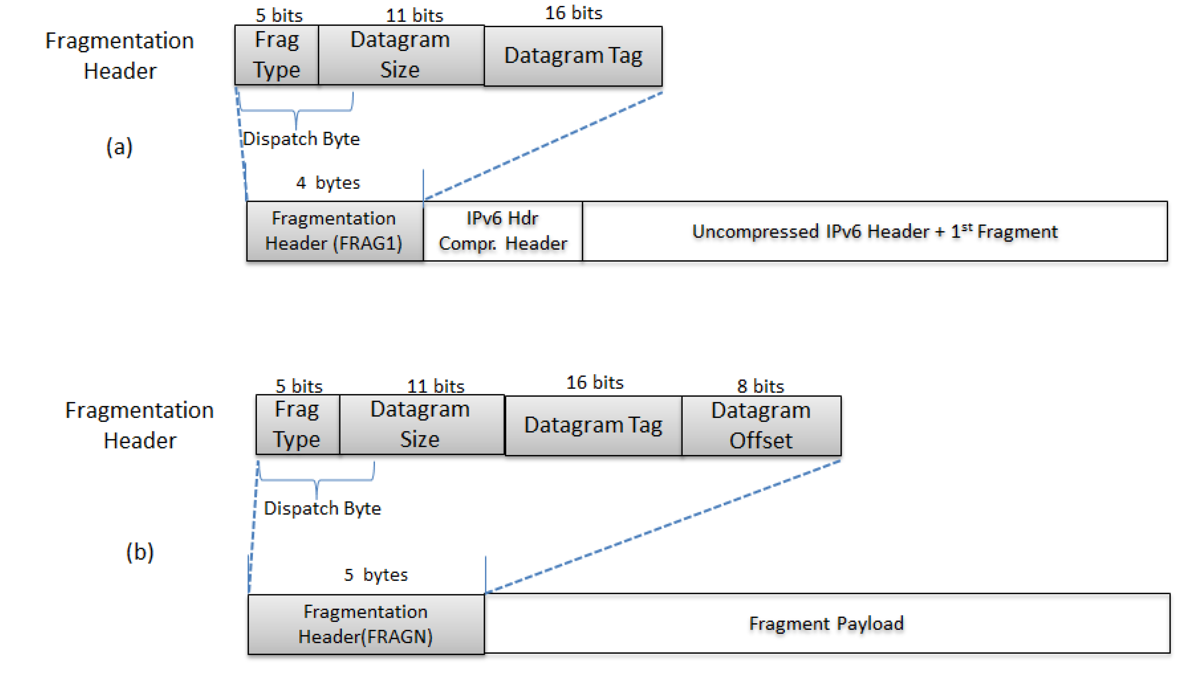
| 11x | Fragmentation Header | The next header is a fragment header. The fragment type is determined by the remaining 6 bits. The bit sequence 000xxx indicates first fragment while 100xxx indicates Non-first fragments. The last three bits in both types of fragments will be used for other purposes. The other bit sequences are reserved. |
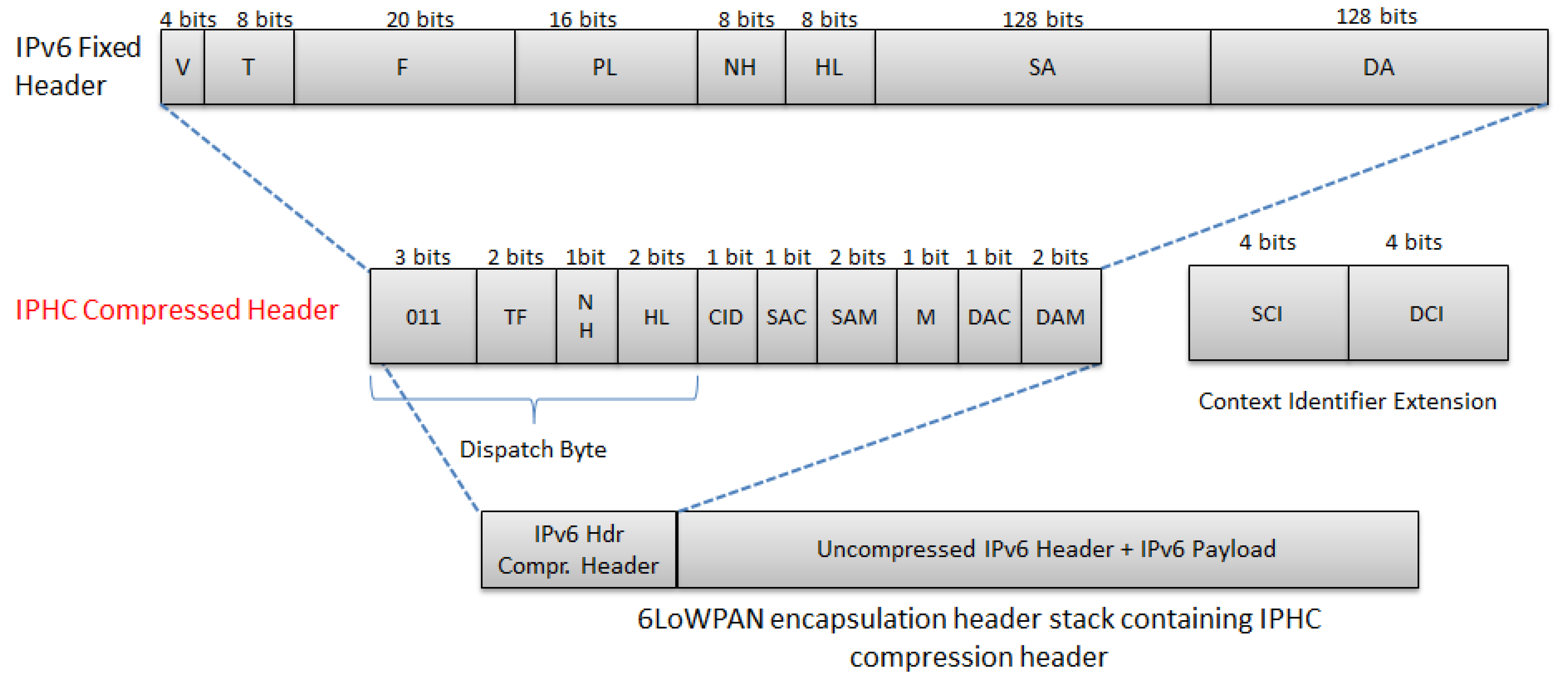
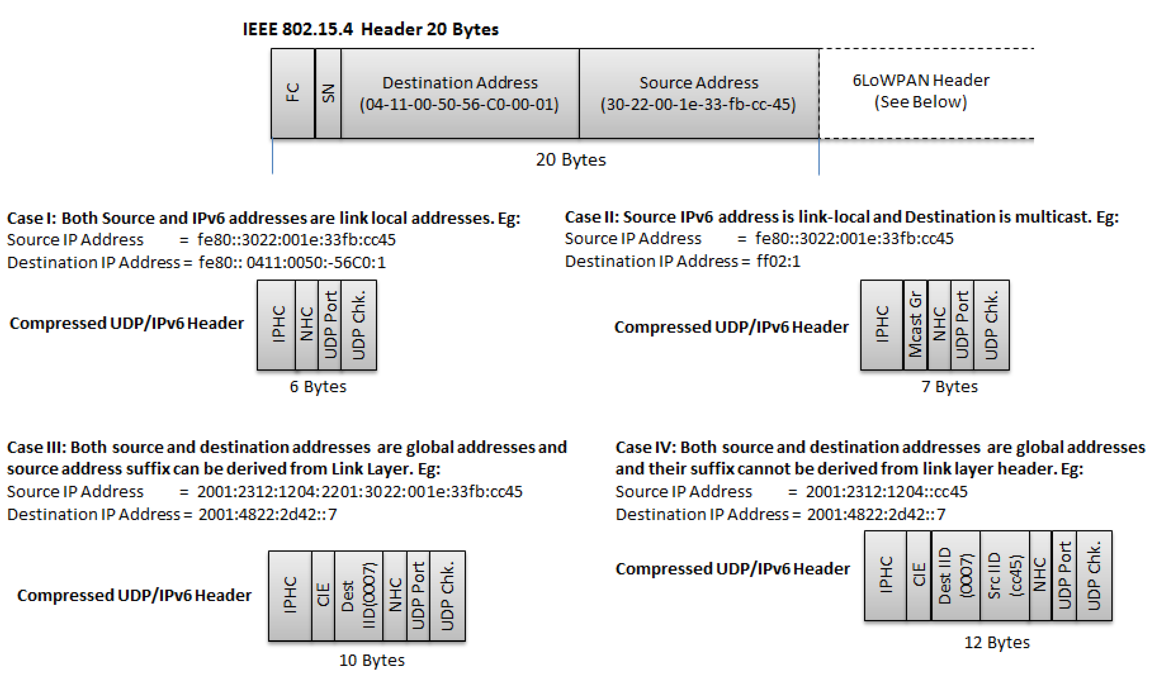
4.1.2. Header Compression

| Field | Description |
|---|---|
| Context ID Extension (CID) (1bit) | 0 = No Additional Context Identifier Extension is used. 1 = An additional 8-bit field follows the DAM field |
| Source Address Compression (SAC) (1 bit) Dest. Address Compression (DAC)(1 bit) | 0 = Stateless source/destination address compression 1 = Stateful, context based source/destination address compression |
| Source Address Mode (SAM) If SAC = 0 | 00 = The full 128 bits address is sent inline 01 = The last 64 bits are sent inline 10 = The last 16 bits are sent inline. 11 = The entire source address is elided |
| If SAC = 1 | 00 = The unspecified address, :: . Nothing is sent inline 01 = 64 bits are carried inline 10 = 16 bits are carried inline 11 = The address is fully elided |
| Multicast Compression (M) | 0 = Destination address is not a multicast address 1 = Destination address is a multicast address |
| Destination Address Mode (DAM) If M = 0 and DAC=0 | Same as SAM with SAC = 0 |
| If M = 0 and DAC = 1 | Same as SAM with SAC = 1 |
| If M = 1 and DAC = 0 | 00 = The full address is sent inline 01 = Only 48 bits are sent inline 10 = Only 32 bits are sent inline 11 = Only 8bits are sent inline |
| If M = 1 and DAC = 1 | 00 = Only 48 bit s are sent inline. 01,10,11 = Reserved |

4.1.3. Fragmentation
4.1.4. Mesh-Under Routing Support
4.2. Implementation and Evaluation
4.2.1. Implementation
| Implementation | Operating System /Simulator | License | RFC 4944 | RFC 6282 | RFC 6775 |
|---|---|---|---|---|---|
| SICSLOWPAN | ContikiOS/Cooja Simulator | Open Source | X | x | x |
| BLIP (Berkley Low-power IP) | TinyOS | Open Source | X | ||
| Arch Rock 6LoWPAN | TinyOS | Open Source | X | ||
| NanoStack 6lowpan | FreeRTOS | Open Source | X | x | x |
| Hitachi | - | Commercial | X | ||
| NS-3 | Simulator | Open Source | X |
4.2.2. Evaluation
4.3. Leveraging upon 6LoWPAN to Realize the IoT
4.3.1. Improvements to Core Specifications
4.3.2. 6LoWPAN over Non IEEE 802.15.4 Technologies
4.3.3. Adoption of 6LoWPAN in Real Life Use Cases
4.3.4. Other Efforts
4.4. Research Challenges
5. IETF ROLL Working Group
5.1. Group Description and Key Protocols
5.1.1. Description
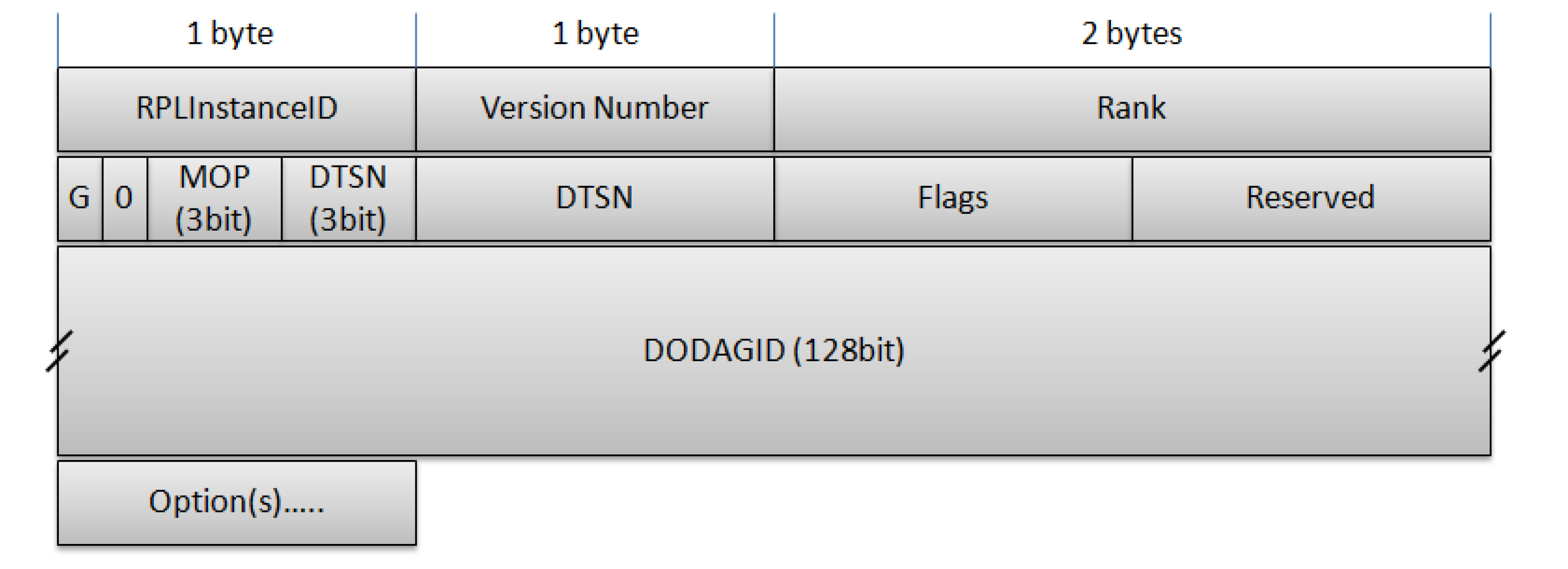
5.1.2. IPv6 Routing Protocol for Low Power and Lossy Networks

| Code Field | RPL Message Type |
|---|---|
| 0x00 | DODAG Information Solicitation (DIS) |
| 0x01 | DODAG Information Object (DIO) |
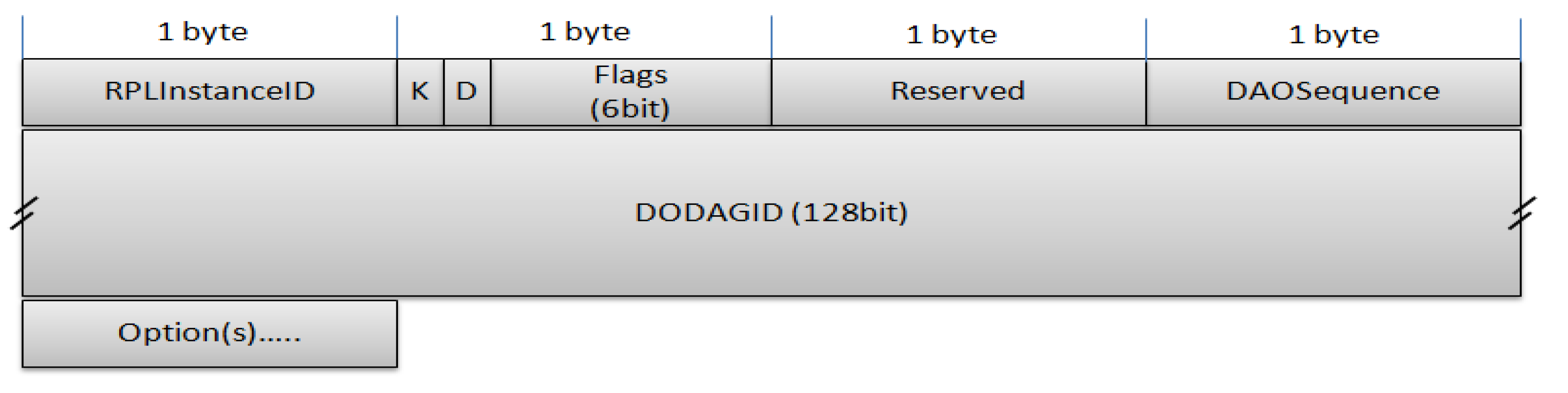
| 0x02 | Destination Advertisement Object (DAO) |
| 0x03 | Destination Advertisement Object Acknowledgment |
| 0x80 | Secure DODAG Information Solicitation |
| 0x81 | Secure DODAG Information Object (DIO) |
| 0x82 | Secure Destination Advertisement Object (DAO) |
| 0x83 | Secure Destination Advertisement Object Acknowledgment |

5.2. Implementation and Evaluation
5.2.1. Implementation
| Name | OS | Protocol Version | Notes (Extensions, ..) |
|---|---|---|---|
| TinyRPL [47] | TinyOS | draft-ietf-roll-rpl-17 | - uses BLIP 2.0 - only storing mode - only single RPLInstanceID - security options not supported - only telosb and epic platform support |
| ContikiRPL [48] | Contiki | RFC 6550 | by default enabled on Tmote sky platform |
| OpenWSN [49] | OpenWSN | RFC 6550 | |
| Nano-RK [50] | Nano-RK | draft-ietf-roll-rpl-07 | |
| NanoQplus [51] | NanoQplus | draft-ietf-roll-rpl-13 |
| Name | Language | Protocol version | Notes (extensions,..) |
|---|---|---|---|
| Cooja [54] | C with limited libs | RFC 6550 | MSPsim (TinyOS + Contiki) |
| NS-3 [55] | C++ and Python | draft-ietf-roll-rpl-19 | |
| OMNET++/Castalia [56] | C++ (wrapped together with NED) | draft-ietf-roll-rpl-19 | |
| J-SIM [57] | Tcl/Java | draft-ietf-roll-rpl-19 | EU-funded FP7 ICT-257245 VITRO project |
5.2.2. Using the Protocol
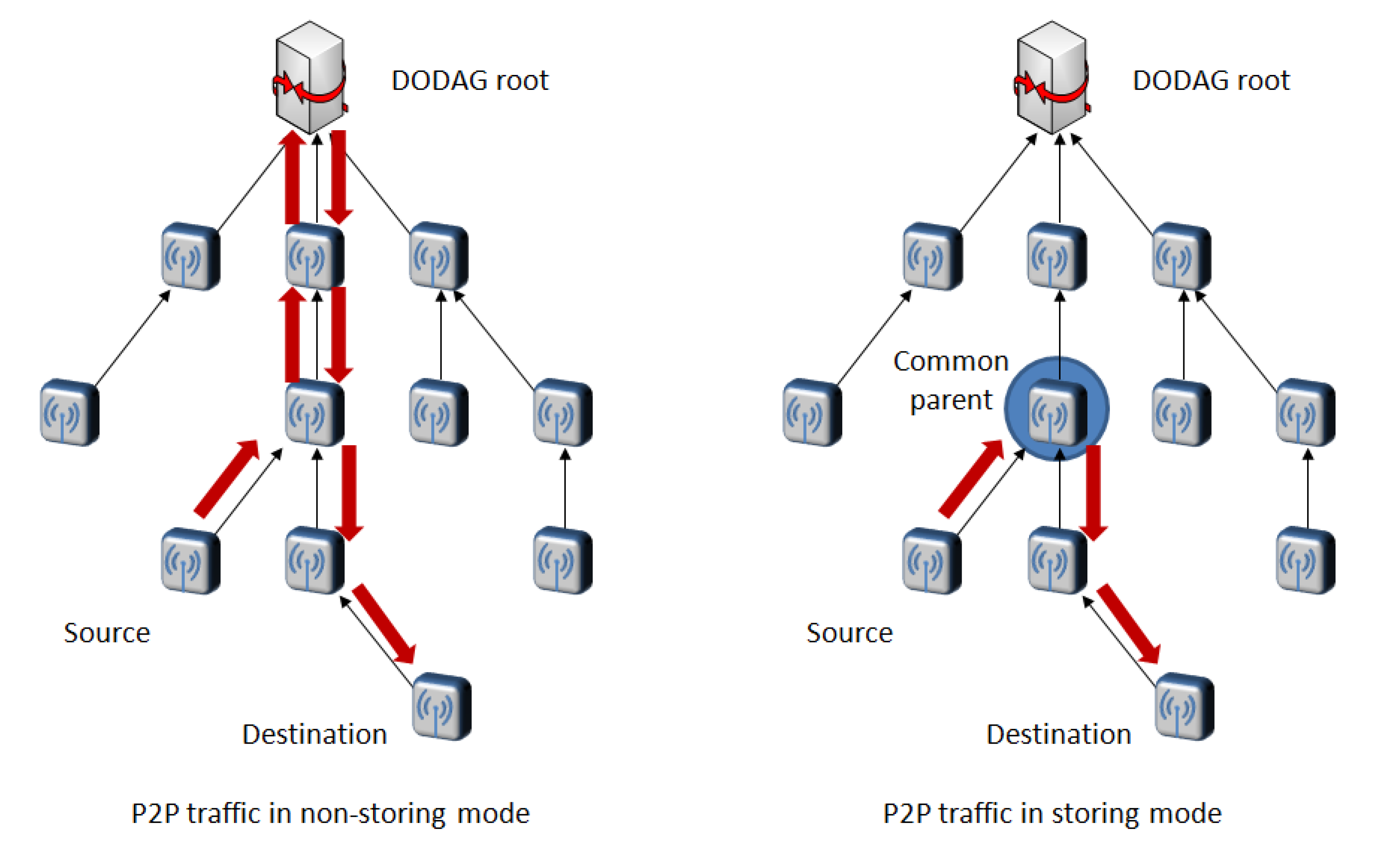
5.2.3. Sensor-to-Sensor Traffic
5.2.4. Multipoint-to-Point Traffic
5.2.5. Multicast
5.2.6. Anycast
5.2.7. Link Estimation
5.2.8. General Performance
5.3. Leveraging upon RPL to Realize the IoT
5.3.1. Real Life Use Cases
5.3.2. Loop-free Repair Mechanisms
5.3.3. Heterogeneity
5.3.4. DIS Handling
5.4. Research Challenges
5.4.1. Interaction with MAC Protocols
5.4.2. Asymmetric Links
5.4.3. Mobility
5.4.4. Multi-Sink Support
5.4.5. Scalability of the Non-Storing RPL Approach
6. IETF CoRE Working Group
6.1. Key Protocols
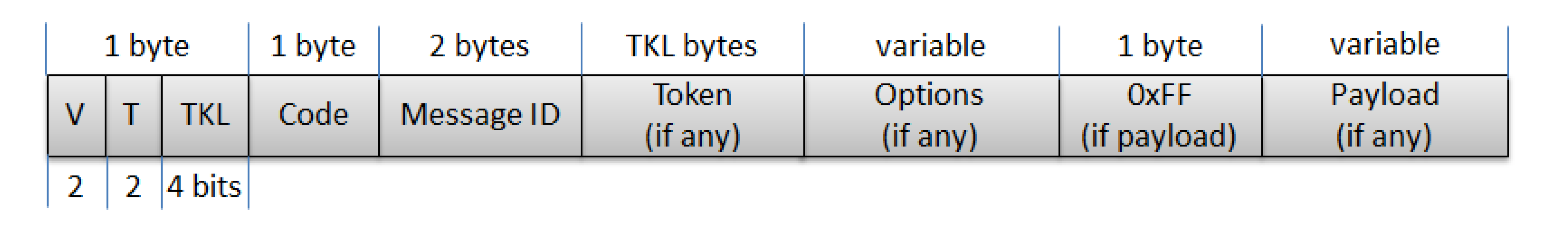
6.1.1. Base CoAP

- Version (V): A 2-bit unsigned integer indicating the CoAP version number. Current version is 1. Other values are reserved for future versions.
- Type (T): A 2-bit unsigned integer indicating if this message is of type Confirmable (0), Non-Confirmable (1), Acknowledgement (2) or Reset (3).
- Token Length (TKL): A 4-bit unsigned integer indicating the length of the variable-length Token field (0-8 bytes). Lengths 9-15 are reserved.
- Code: An 8-bit unsigned integer indicating if the message carries a request (1-31) or a response (64-191), or is empty (0). (All other code values are reserved.) In case of a request, the Code field indicates the Request Method (1: GET; 2: POST; 3: PUT; 4: DELETE); in case of a response a Response Code. Possible values are maintained in the CoAP Code Registry (see section 12 of the draft).
- Message ID: A 16-bit unsigned integer in network byte order used for the detection of message duplication, and to match messages of type Acknowledgement/Reset to messages of type Confirmable/ Non-confirmable.
- Token: 0 to 8 bytes, as given by the Token Length field. The Token value is used to correlate requests and responses. The rules for generating a Token and correlating requests and responses are defined in Section 5 of the draft.
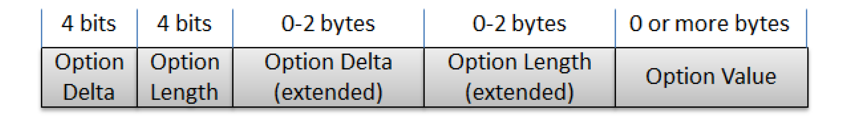
- Options: An Option can be followed by the end of the message, by another Option, or by the Payload Marker and the payload. The format of the Options field is shown in Figure 14 and is described in more detail in the next paragraph.
- Payload: If present and of non-zero length, it is prefixed by a fixed, one-byte Payload Marker (0xFF) which indicates the end of options and the start of the payload. The payload data extends from after the marker to the end of the UDP datagram, i.e., the Payload Length is calculated from the datagram size. The absence of the Payload Marker denotes a zero-length payload.

- Option Delta: 4-bit unsigned integer. A value between 0 and 12 indicates the Option Delta. A value of 13 indicates that an 8-bit unsigned integer follows the initial byte and indicates the Option Delta minus 13. A value of 14 indicates that a 16-bit unsigned integer in network byte order follows the initial byte and indicates the Option Delta minus 269. The value 15 is reserved for the Payload Marker and cannot be used here. The resulting Option Delta is used as the difference between the Option Number of this option and that of the previous option (or zero for the first option).
- Option Length: 4-bit unsigned integer. A value between 0 and 12 indicates the length of the Option Value, in bytes. A value of 13 indicates that an 8-bit unsigned integer precedes the Option Value and indicates the Option Length minus 13. A value of 14 indicates that a 16-bit unsigned integer in network byte order precedes the Option Value and indicates the Option Length minus 269. The value 15 is reserved for future use.
- Value: A sequence of exactly Option Length bytes. The length and format of the Option Value depend on the respective option, which may define variable length values.
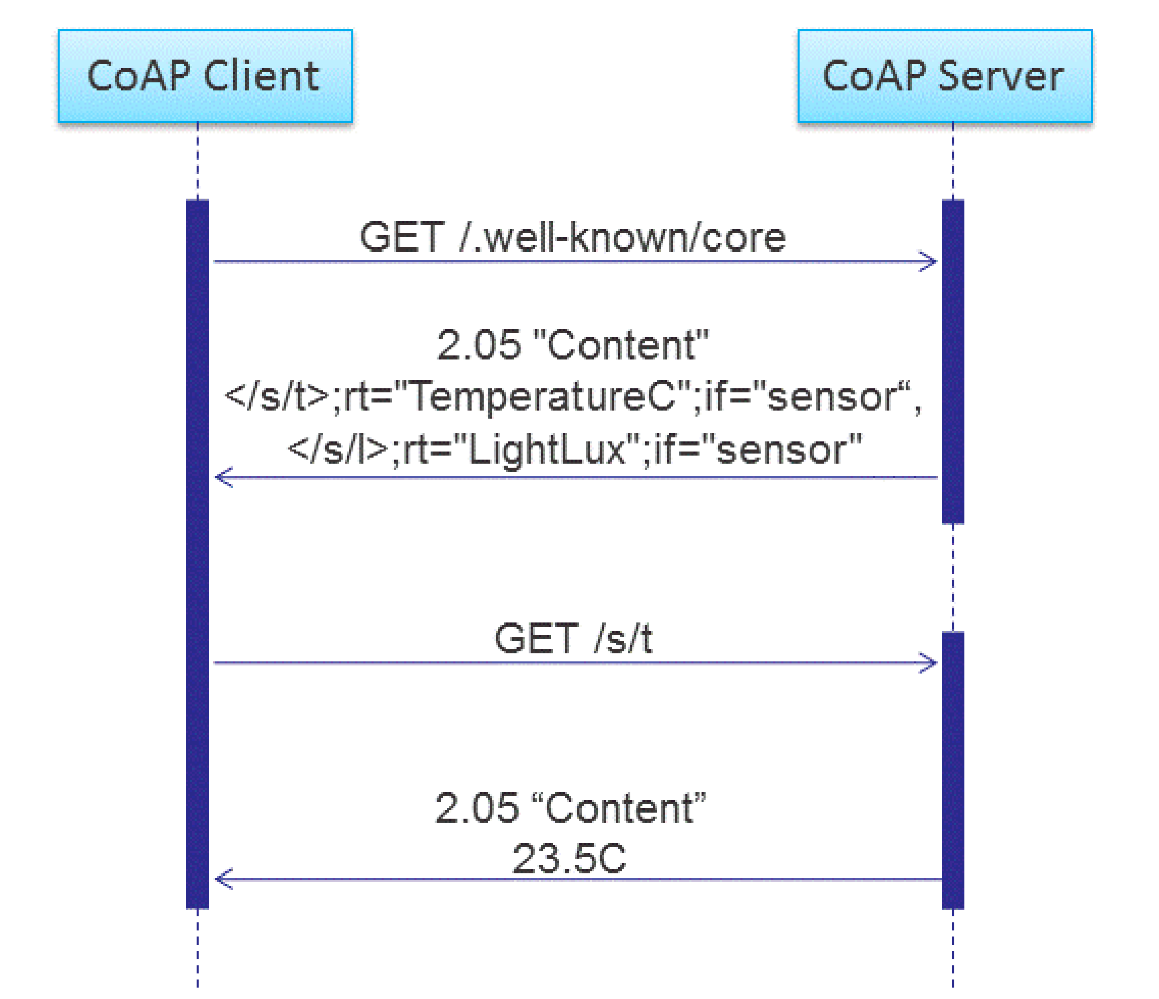
6.1.2. CoRE Link Format
6.1.3. Block Transfer
6.1.4. Observation of Resource
6.2. Implementation and Evaluation
6.2.1. CoAP Implementations
| Name/ Company | License | Language | Platform | Notes |
|---|---|---|---|---|
| Consorzio Ferrara Ricerche [93] | NesC/C | TinyOS | Own “SiGLoWPAN” IPv6/6LoWPAN stack for Class 1 devices | |
| Californium [94]/ETH Zurich | 3-clause BSD | Java | JVM | Framework for unconstrained devices; provides client, server, and proxy stubs |
| Copper [95]/ETH Zurich | 3-clause BSD | JavaScript | Firefox | Management and testing tool as a browser extension; focus on user interaction |
| Erbium [96]/ETH Zurich | 3-clause BSD | C | Contiki | For class 1 devices such as sensor nodes |
| CoAP++ [97]/iMinds | C++ | Click ModularRouter | Framework for unconstrained devices; provides client, server, proxy and gateway | |
| Evcoap [98]/KoanLogic | 2-clause BSD | C | Linux | General purpose protocol implementation |
| Patavina Technologies [93] | Commercial | C++ | proprietaryOS | Wired and wireless embedded devices and sensor nodes; working on a port to uC/OS by Micrium |
| NanoService Device Library [99]/Sensinode | Commercial | C | OS-independent C library for Class 1 and 2 devices. Also available a JAVA SDK for unconstrained devices | |
| libcoap [100]/Universität Bremen TZI | GPLv2,2-clause BSD | C | POSIX andContiki | General purpose library for Class 1 and 2 devices and up |
| CoapBlip [101]/Universität Bremen TZI | BSD-style | C | TinyOS | TinyOS-port of “libcoap”; runs on Class 1 devices. |
| coap.me [102]/Universität Bremen TZI | Ruby | http://coap.me provides an HTTP front-end to crawl CoAP servers, and a CoAP server for interoperability testing | ||
| jCoAP [103]/Universität Rostock | Apache 2.0 | Java | JVM | For unconstrained devices; also targets mobile and embedded platforms |
| Scuola Superiore Sant'Anna [104] | Erika API | Erika OS | A middleware for building an infrastructure of wireless sensor nodes. | |
| CoAPy [105]/People Power | BSD | Python | Last updated on July 2010 | |
| CoAP in wiselib [106]/wisebed project | GNU Lesser GPL v3 | c++ | Wiselib algorithm classes can be compiled for several sensor platforms such as iSense or Contiki, or the simulator Shawn. |
6.2.2. CoAP Performance Evaluation
6.3. Leveraging Upon CoAP to Realize the IoT
6.3.1. Discovery and Naming
6.3.2. Congestion Control
6.3.3. Advanced Interaction Patterns
6.3.4. Communication with Sleepy Nodes
6.3.5. Security
6.3.6. Intermediaries
6.3.7. CoAP in Cellular Networks
6.3.8. Real Life Use Cases of CoAP in the IoT
6.4. Research Challenges
7. Using IETF Standards to Realize the Internet of Things
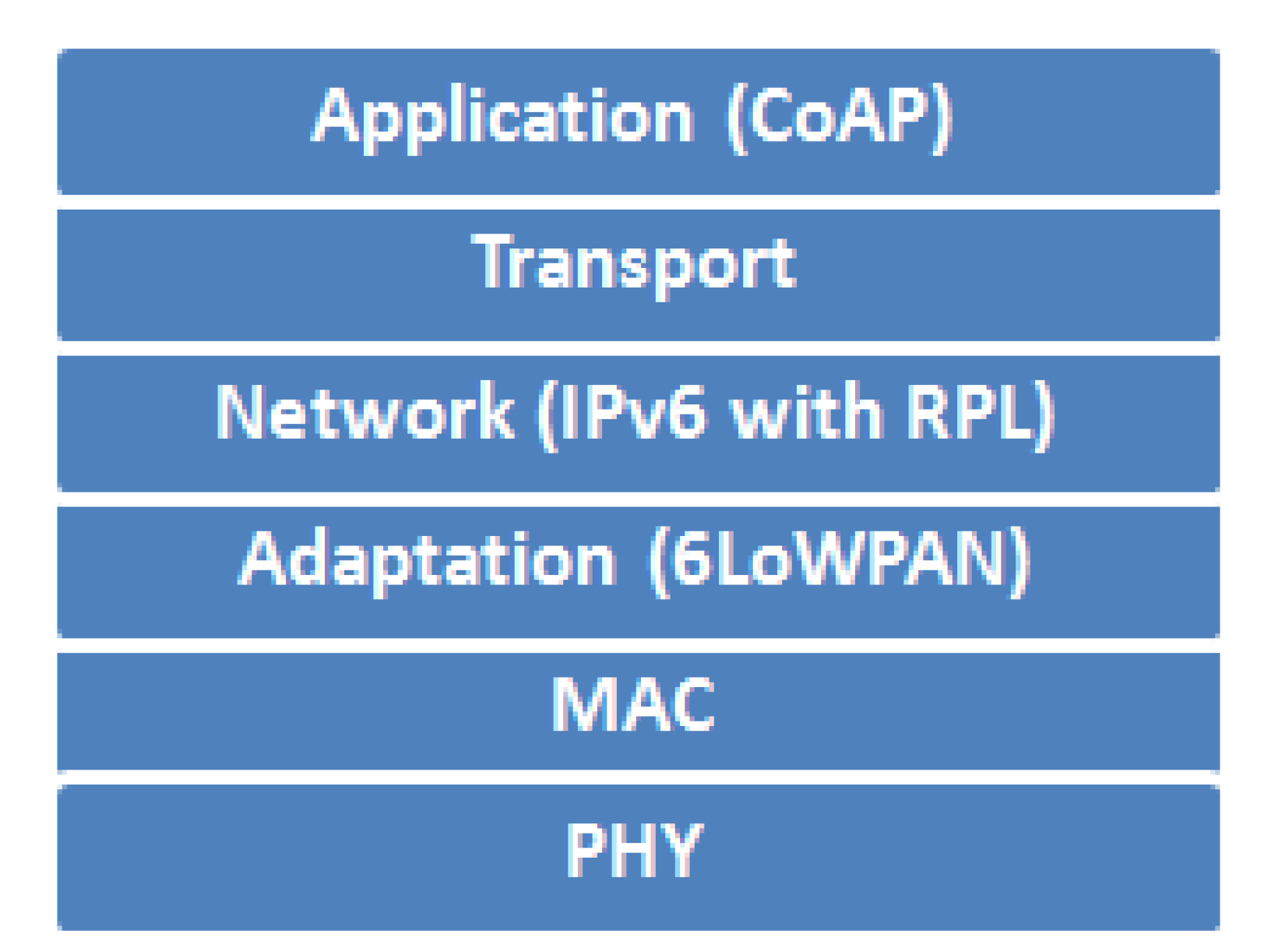
7.1. Overview of the IETF LLN Protocol Stack
7.2. Realizing the Web of Things
7.3. Interoperability
7.4. Bringing Semantics to the Web of Things
7.5. Security and Privacy in the Web of Things
7.6. Reprogrammability
8. Conclusions
Acknowledgments
Conflict of Interest
References
- Kushalnagar, N.; Montenegro, G.; Schumacher, C.P.P. IPv6 over Low-Power Wireless Personal Area Networks (6LoWPANs): Overview, assumptions, problem statement, and goals. 2007; 1–2IETF RFC 4919. [Google Scholar]
- Montenegro, G.; Kushalnagar, N.; Hui, J.; Culler, D. Transmission of IPv6 Packets over IEEE 802.15.4 Networks. 2007; 1–30IETF RFC 4944. [Google Scholar]
- Routing Over Low power and Lossy networks (roll). Available online: http://datatracker.ietf.org/wg/roll/ (accessed on 3 October 2012).
- ZigBee Alliance Plans Further Integration of Internet Protocol Standards. Available online: https://docs.zigbee.org/zigbee-docs/dcn/09-5003.pdf (accessed on 3 October 2012).
- Constrained RESTful Environments (core). Available online: http://datatracker.ietf.org/wg/core/ (accessed on 28 December 2012).
- IPv6 over Low power WPAN (6lowpan). Available online: http://datatracker.ietf.org/wg/6lowpan/ (accessed on 28 December 2012).
- Constrained RESTful Environments (core). Available online: http://datatracker.ietf.org/wg/core/ (accessed on 28 December 2012).
- IEEE 802.15.4. Available online: http://www.ieee802.org/15/pub/TG4.html (accessed on 28 December 2012).
- IEEE Standard for Local and Metropolitan Area Networks—Part 15.4: Low-Rate Wireless Personal Area Networks (LR-WPANs). 5 September 2011; 1–314.
- ZigBee Alliance. Available online: http://www.zigbee.org/ (accessed on 28 December 2012).
- HART Communication Protocol and Foundation. Available online: http://www.hartcomm.org/ (accessed on 28 December 2012).
- MiWi Development Environment. Available online: http://www.microchip.com/miwi (accessed on 28 December 2012).
- ISA100 Wireless Systems for Automation. Available online: http://www.isa.org/isa100 (accessed on 28 December 2012).
- Vasseur, J.-P.; Dunkels, A. Interconnecting Smart Objects with IP: The Next Internet; Morgan Kaufmann: Amsterdam, Holand, 2010. [Google Scholar]
- Montenegro, G.; Kushalnagar, N.; Hui, J.W.; Culler, D.E. Transmission of IPv6 Packets over IEEE 802.15.4 Networks. IETF RFC 4944, 2007.
- Hui, J.; Thubert, P. Compression Format for IPv6 Datagrams over IEEE 802.15.4-Based Networks. IETF RFC 6282, 2011; 1–24. [Google Scholar]
- Chakrabarti, S.; Nordmark, E.; Bormann, C. Neighbor Discovery Optimization for IPv6 over Low-Power Wireless Personal Area Networks (6LoWPANs); Shelby, Z., Ed.; IETF RFC 6775; 2012; pp. 1–55. [Google Scholar]
- Kim, E.; Kaspar, D. Design and Application Spaces for IPv6 over Low-Power Wireless Personal Area Networks (6LoWPANs). IETF RFC 6568, 2012; 1–28. [Google Scholar]
- Gomez, C.; Kim, E.; Kaspar, D.; Bormann, C. Problem Statement and Requirements for IPv6 over Low-Power Wireless Personal Area Network (6LoWPAN) Routing. IETF RFC 6606, 2007. [Google Scholar]
- Nieminen, J.; Savolainen, T.; Isomaki, M.; Shelby, Z.; Gomez, C. Transmission of IPv6 Packets over BLUETOOTH Low Energy. draft-ietf-6lowpan-btle-11. 2012. [Google Scholar]
- IPv6 Over Low power WPAN (6LoWPAN) Charter. Available online: http://datatracker.ietf.org/wg/6lowpan/charter/ (accessed on 13 December 2012).
- Hui, J.; Culler, D.; Chakrabarti, S. 6LoWPAN: Incorporating IEEE 802.15.4 into the IP architecture 2009. 17.
- Mulligan, G. The 6LoWPAN Architecture. In Proceedings of the 4th Workshop on Embedded Networked Sensors, Cork, Ireland, 25–26 June 2007; ACM: New York, NY, USA, 2007; pp. 78–82. [Google Scholar]
- Cody-Kenny, B.; Guerin, D.; Ennis, D.; Carbajo, R.S.; Huggard, M.; McGoldrick, C. Performance Evaluation of the 6LoWPAN Protocol on MICAz and TelosB Motes. In Proceedings of 4th ACM Workshop on Performance Monitoring and Measurement of Heterogeneous Wireless and Wired Networks, Tenerife, Canary Islands, Spain, 26 October 2009; ACM: New York, NY, USA, 2009; pp. 25–30. [Google Scholar]
- Sulthana, M.R.; Bhuvaneswari, P.T.V.; Rama, N. Routing Protocols in 6LoWPAN: A Survey. Eur. J. Sci. Res. 2012, 85, 248–261. [Google Scholar]
- Borman, C. 6LoWPAN Generic Compression of Headers and Header-like Payloads. draft-bormann-6lowpan-ghc-05. 2012. [Google Scholar]
- Sahara Project. Available online: http://sahara.tzi.org/ (accessed on 10 December 2012).
- HOBNET project. Available online: http://www.hobnet-project.eu/ (accessed on 10 December 2012).
- Outsmart: FP7 Framework Project. Available online: http://www.fi-ppp-outsmart.eu/en-uk/Pages/default.aspx (accessed on 10 December 2012).
- Cassaniti, D. A Multihop 6LoWPAN Wireless Sensor Network for Waste Management Optimization. M.Sc. thesis, University of Padova, Padova, Italy, 2012; p. 154. [Google Scholar]
- Calipso Project. Available online: http://www.ict-calipso.eu/ (accessed on 10 December 2012).
- Khoshdelniat, R. LoWPAN Applications and Internet of Things. Available online: http://www.apan.net/meetings/Hanoi2010/Session/SensNet.php (accessed on 10 December 2012).
- Schoenwaelder, J.; Sehgal, A.; Tsou, T.; Zhou, C. Definition of Managed Objects for IPv6 over Low-Power Wireless Personal Area Networks (6LoWPANs). draft-schoenw-6lowpan-mib-01. 2012. [Google Scholar]
- Bormann, C. Guidance for Light-Weight Implementations of the Internet Protocol Suite. draft-ietf-lwig-guidance-02. 2012. [Google Scholar]
- Altmann, V.; Skodzik, J.; Golatowski, F.; Timmermann, D. Investigation of the Use of Embedded Web Services in Smart Metering Applications. In Proceedigns of the 38th Annual Conference of the IEEE Industrial Electronics Society (IECON2012), Montréal, PQ, Canada, 25–28 October 2012.
- Routing over Low power and Lossy networks (roll)—Charter. Available online: http://datatracker.ietf.org/wg/roll/charter/ (accessed on 27 December 2012).
- Pister, K.; Thubert, P.; Phinney, T. Industrial Routing Requirements in Low-Power and Lossy Networks. IETF RFC 5673, 2009; 1–27. [Google Scholar]
- Buron, J.; Brandt, A.; Porcu, G. Home Automation Routing Requirements in Low-Power and Lossy Networks. IETF RFC 5826, 2010; 1–17. [Google Scholar]
- Martocci, J.; Mil, P. De; Riou, N.; Vermeylen, W. Building Automation Routing Requirements in Low-Power and Lossy Networks. IETF RFC 5867, 2010; 1–26. [Google Scholar]
- Watteyne, T.; Berkeley, U.C.; Winter, T.; Barthel, D. Routing Requirements for Urban Low-Power and Lossy Networks. IETF RFC 5548, 2009; 1–21. [Google Scholar]
- Winter, T.; Thubert, P.; Brandt, A.; Hui, J.; Kelsey, R.; Levis, P.; Pister, K.; Struik, R.; Vasseur, J.P.; Alexander, R. RPL: IPv6 routing protocol for low-power and lossy networks. IETF RFC 6550, 2013; 1–157. [Google Scholar]
- Vasseur, J.; Kim, M.; Pister, K.; Dejean, N.; Barthel, D. Routing metrics used for path calculation in low power and lossy networks. IETF RFC 6551, 2011; 1–30. [Google Scholar]
- Thubert, P. Objective Function Zero for the Routing Protocol for Low-Power and Lossy Networks (RPL). IETF RFC 6552, 2012; 1–14. [Google Scholar]
- Gnawali, O.; Levis, P. The Minimum Rank with Hysteresis Objective Function. IETF RFC 6719, 2012; 1–13. [Google Scholar]
- Clausen, T.; Gnawali, O.; Ko, J.; Hui, J. The Trickle Algorithm. IETF RFC 6206, 2011; 1–13. [Google Scholar]
- Conta, A.; Gupta, M. Internet control message protocol (icmpv6) for the internet protocol version 6 (ipv6) specification. IETF RFC 4443, 2006; 1–24. [Google Scholar]
- TinyRPL—TinyOS Documentation Wiki. Available online: http://docs.tinyos.net/tinywiki/index.php/TinyRPL (accessed on 27 December 2012).
- Tsiftes, N.; Eriksson, J.; Dunkels, A. Low-power Wireless IPv6 Routing with ContikiRPL. In Proceedings of the 9th ACM/IEEE International Conference on Information Processing in Sensor Networks, IPSN ’10, Stockholm, Sweden, 12–16 April 2010; ACM Press: : New York, NY, USA, 2010; p. 406. [Google Scholar]
- Berkeley’s OpenWSN Project. Available online: http://openwsn.berkeley.edu/ (accessed on 28 December 2012).
- Nano-RK. Available online: http://www.nanork.org/projects/nanork (accessed on 28 December 2012).
- Jeong, J. Design and Implementation of Low Power Wireless IPv6 Routing for NanoQplus. In Proceedings of the 13th International Conference on Advanced Communication Technology (ICACT), Daejeon, South Korea, 13–16 February 2011; pp. 966–971.
- Pavković, B.; Theoleyre, F.; Duda, A. Multipath Opportunistic RPL Routing over IEEE 802.15.4. In Proceedings of the 14th ACM International Conference on ModelingAnalysis and Simulation of Wireless and Mobile Systems, MSWiM ’11, Miami Beach, FL, USA, 31 October 2011; ACM Press: New York, NY, USA, 2011; p. 179. [Google Scholar]
- Saad, L.; Chauvenet, C.; Tourancheau, B. Simulation of the RPL Routing Protocol for IPv6 Sensor Networks: Two Cases Studies. In Proceedings of the International Conference on Sensor Technologies and Applications, Nice, France, 21–27 August 2011; Volume 2011.
- Contiki: The Open Source Operating System for the Internet of Things. Available online: http://www.contiki-os.org/ (accessed on 20 December 2012).
- Bartolozzi, L.; Pecorella, T.; Fantacci, R. ns-3 RPL module: IPv6 routing protocol for low power and lossy networks. In Proceedings of the 5th International ICST Conference on Simulation Tools and Techniques (SIMUTOOLS), Desenzano, Italy, 19–23 March 2012; pp. 359–366.
- Hammerseth, S.K. Implementing RPL in a Mobile and Fixed Wireless Sensor Network with OMNeT++. M.Sc. Thesis, University of Oslo, Oslo, Norway, 29 November 2012; pp. 1–101. [Google Scholar]
- rpl-jsim-platform—Implementation of RPL functionality in JSim platform—Google Project Hosting. Available online: http://code.google.com/p/rpl-jsim-platform/ (accessed on on 20 December 2012).
- Gnawali, O.; Levis, P. Recommendations for Efficient Implementation of RPL. draft-gnawali-roll-rpl-recommendations-04. 2012. [Google Scholar]
- Tripathi, J.; Oliveira, J.; Vasseur, J.-P. Performance Evaluation of the Routing Protocol for Low-Power and Lossy Networks (RPL). IETF RFC 6687, 2012; 1–26. [Google Scholar]
- Ko, J.; Eriksson, J.; Tsiftes, N.; Dawson-haggerty, S.; Terzis, A.; Dunkels, A.; Culler, D. ContikiRPL and TinyRPL: Happy Together. In Proceedings of the workshop on Extending the Internet to Low power and Lossy Networks (IP+SN), Chicago, IL, USA, 11 April 2011.
- Clausen, T. H.; Herberg, U.; Philipp, M. A Critical Evaluation of the IPv6 Routing Protocol for Low Power and Lossy Networks(RPL). In Proceedings of the 2011 IEEE 7th International Conference on Wireless and Mobile ComputingNetworking and Communications (WiMob), Wuhan, China, 23–25 September 2011; pp. 365–372.
- Xie, W.; Goyal, M.; Hosseini, H.; Martocci, J.; Bashir, Y.; Baccelli, E.; Durresi, A. A Performance Analysis of Point-to-Point Routing along a Directed Acyclic Graph in Low Power and Lossy Networks. In Proceedings of the 13th International Conference on Network-Based Information Systems (NBiS), Takayama, Japan, 14–16 September 2010; pp. 111–116.
- Baccelli, E.; Philipp, M.; Goyal, M. The P2P-RPL Routing Protocol for IPv6 Sensor Networks: Testbed Experiments. In Proceedings of the 19th International Conference on SoftwareTelecommunications and Computer Networks (SoftCOM), Split, Croatia, 15–17 September 2011; pp. 1–6.
- Hui, J.; Kelsey, R. Multicast Protocol for Low power and Lossy Networks (MPL). draft-ietf-roll-trickle-mcast-02. 2012; 1–24. [Google Scholar]
- Oikonomou, G.; Phillips, I. Stateless Multicast Forwarding with RPL in 6LowPAN Sensor Networks. In Proceedings of the 2012 IEEE International Conference on Pervasive Computing and Communications Workshops (PerCom), City, Country, 19–23 March 2012; pp. 272–277.
- Dawans, S.; Duquennoy, S.; Bonaventure, O. On Link Estimation in Dense RPL Deployments. In Proceedings of the International Workshop on Practical Issues in Building Sensor Network Applications (IEEE SenseApp 2012), Clearwater, FL, USA, 22–25 October 2012; pp. 956–959.
- Goyal, M.; Baccelli, E.; Brandt, A.; Martocci, J. A Mechanism to Measure the Routing Metrics along a Point-to-point Route in a Low Power and Lossy Network. draft-ietf-roll-p2p-measurement-07. 2013; 1–26. [Google Scholar]
- Goyal, M.; Baccelli, E.; Philipp, M.; Brandt, A.; Martocci, J. Reactive Discovery of Point-to-Point Routes in Low Power and Lossy Networks. draft-ietf-roll-p2p-rpl-15. 2012; 1–36. [Google Scholar]
- Herberg, U.; Clausen, T. A Comparative Performance Study of the Routing Protocols LOAD and RPL with Bi-directional Traffic in Low-power and Lossy Networks (LLN). In Proceedings of the 8th ACM Symposium on Performance Evaluation of Wireless ad Hoc, Sensor and Ubiquitous Networks (PE-WASUN), Miami Beach, FL, USA, 31 October–4 November 2011; ACM Press: New York, NY, USA, 2011; pp. 73–80. [Google Scholar]
- Ko, J.; Gnawali, O.; Culler, D.; Terzis, A. Evaluating the Performance of RPL and 6LoWPAN in TinyOS. In Proceedings of the Workshop on Extending the Internet to Low power and Lossy Networks (IP+SN), Chicago, IL, USA, 11 April 2011.
- Accettura, N.; Grieco, L.A.; Boggia, G.; Camarda, P. Performance analysis of the RPL Routing Protocol. In Proceedings of IEEE International Conference on Mechatronics, Istanbul, Turkey, 13–15 April 2011; pp. 767–772.
- Bressan, N.; Bazzaco, L.; Bui, N.; Casari, P.; Vangelista, L.; Zorzi, M. The Deployment of a Smart Monitoring System Using Wireless Sensor and Actuator Networks. In Proceedings of the First IEEE International Conference on Smart Grid Communications (SMARTGRIDCOMM), Gaithersburg, Maryland, USA, 4–6 October 2010; pp. 49–54.
- Chen, Y.; Chanet, J.P.; Hou, K.M. RPL Routing Protocol a case study: Precision agriculture. In Proceedings of the First China-France Workshop on Future Computing Technology (CF-WoFUCT 2012), Harbin, China, 16–17 February 2012.
- Becker, M.; Pötsch, T.; Kuladinithi, K.; Görg, C. Deployment of CoAP in Transport Logistics. In Proceedings of 36th IEEE Conference on Local Computer Networks (LCN), Bonn, Germany, 4–7 October 2011; pp. 1–3.
- Guo, J.; Orlik, P.; Bhatti, G. Loop Free DODAG Local Repair. draft-guo-roll-loop-free-dodag-repair-00. 2012; 1–17. [Google Scholar]
- Guo, J.; Orlik, P.; Bhatti, G. Loop Free RPL. draft-guo-roll-loop-free-rpl-01. 2013; 1–20. [Google Scholar]
- Ko, J.; Jeong, J.; Park, J.; Jun, J.; Kim, N. RPL Routing Pathology In a Network With a Mix of Nodes Operating in Storing and Non-Storing Modes. draft-ko-roll-mix-network-pathology-01. 2012; 1–9. [Google Scholar]
- Baryun, A. The Node Ability of Participation (NAP). draft-baryun-roll-nap-00. 2013; 1–9. [Google Scholar]
- Goyal, M.; Barthel, D.; Baccelli, E. DIS Modifications. draft-goyal-roll-dis-modifications-01. 2013; 1–11. [Google Scholar]
- Hong, K.-S.; Choi, L. DAG-based multipath routing for mobile sensor networks. In Proceedings of the International Conference on ICT Convergence (ICTC), Seoul, Korea (South), 28–30 September 2011; pp. 261–266.
- Lee, K.C.; Sudhaakar, R.; Ning, J.; Dai, L.; Addepalli, S.; Vasseur, J.P.; Gerla, M. A Comprehensive Evaluation of RPL under Mobility. Int. J. Veh. Technol. 2012, 2012, 1–10. [Google Scholar]
- Carels, D.; Poorter, E.De; Moerman, I.; Demeester, P. Extending the IETF RPL routing protocol with mobility support. 2013. In press. [Google Scholar]
- Shelby, Z.; Hartke, K.; Bormann, C.; Frank, B. Constrained Application Protocol (CoAP). draft-ietf-core-coap-13. 2012. [Google Scholar]
- Colitti, W.; Steenhaut, K.; Caro, N. De Integrating Wireless Sensor Networks with the Web. In Proceedings of Workshop on Extending the Internet to Low power and Lossy Networks, Chicago, IL, USA, 11 April 2011.
- Yazar, D.; Dunkels, A. Efficient Application Integration in IP-based Sensor Networks. In Proceedings of the First ACM Workshop on Embedded Sensing Systems for Energy-Efficiency in Buildings, BuildSys’09, Berkeley, USA, 4–6 November 2009; ACM Press: New York, NY, USA, 2009; p. 43. [Google Scholar]
- Shelby, Z. Embedded web services. IEEE Wirel. Commun. 2010, 291, 76–81. [Google Scholar]
- Shelby, Z. Constrained RESTful Environments (CoRE) Link Format. IETF RFC 6690, 2012.
- Bormann, C.; Shelby, Z. Blockwise transfers in CoAP. draft-ietf-core-block-10. 2012. [Google Scholar]
- Hartke, K. Observing Resources in CoAP. draft-ietf-core-observe-07. 2012. [Google Scholar]
- 1st CoAP Plugtest, Technical Report CTI Plugtest Report 1.1.1. 2012.
- Velez, L. IoT COAP#2 Interop Event Preliminary Report. Available online: http://svn.tools.ietf.org/svn/wg/core/Preliminary-Results-CoAP%232.pdf (accessed on 28 December 2012).
- Lerche, C.; Hartke, K.; Kovatsch, M. Industry Adoption of the Internet of Things: A Constrained Application Protocol Survey. In Proceedings of the 7th International Workshop on Service Oriented Architectures in Converging Networked Environments (SOCNE 2012), Kraków, Poland, 17–21 September 2012.
- Castellani, A.P.; Gheda, M.; Bui, N.; Rossi, M.; Zorzi, M. Web Services for the Internet of Things through CoAP and EXI. In Proceedings of IEEE International Conference on Communications Workshops (ICC), Kyoto, Japan, 5–9 June 2011; pp. 1–6.
- Californium (Cf) CoAP framework in Java. Available online: http://people.inf.ethz.ch/mkovatsc/californium.php (accessed on 28 December 2012).
- Copper (Cu) Add-ons for Firefox. Available online: https://addons.mozilla.org/en-us/firefox/addon/copper-270430/ (accessed on 28 December 2012).
- Erbium (Er) REST Engine and CoAP Implementation for Contiki. Available online: http://people.inf.ethz.ch/mkovatsc/erbium.php (accessed on 28 December 2012).
- Ishaq, I.; Hoebeke, J.; Rossey, J.; De Poorter, E.; Moerman, I.; Demeester, P. Facilitating Sensor Deployment,Discovery and Resource Access Using Embedded Web Services. In Proceedings of the Sixth International Conference on Innovative Mobile and Internet Services in Ubiquitous Computing, Palermo, Italy, 4–6 July 2012; pp. 717–724.
- evcoap. Available online: https://github.com/koanlogic/webthings/tree/master/bridge/sw/lib/evcoap (accessed on 29 December 2012).
- NanoService. Sensinode Ltd. Available online: http://www.sensinode.com/EN/products/nanoservice.html (accessed on 22 December 2012).
- libcoap: C-Implementation of CoAP. Available online: http://libcoap.sourceforge.net/ (accessed on 22 December 2012).
- CoAP. TinyOS Documentation Wiki. Available online: http://docs.tinyos.net/tinywiki/index.php/CoAP (accessed on 22 December 2012).
- coap.me. Available online: http://coap.me/ (accessed on 22 December 2012).
- jcoap is a Java Library implementing the Constrained Application Protocol (CoAP)—Google Project Hosting. Available online: http://code.google.com/p/jcoap (accessed on 22 December 2012).
- Constraint Application Protocol (CoAP) for ERIKA embedded OS. Available online: http://rtn.sssup.it/index.php/research-activities/middleware-of-things/middleware-of-things/11-research-activities/35-coaperika (accessed on 22 December 2012).
- CoAPy: Constrained Application Protocol in Python—CoAPy v0.0.2 documentation. Available online: http://coapy.sourceforge.net/ (accessed on 29 December 2012).
- ibr-alg/wiselib. GitHub. Available online: https://github.com/ibr-alg/wiselib (accessed on 22 December 2012).
- Colitti, W.; Steenhaut, K.; De Caro, N.; Buta, B.; Dobrota, V. Evaluation of Constrained Application Protocol for Wireless Sensor Networks. In Proceedings of the 18th IEEE Workshop on Local & Metropolitan Area Networks (LANMAN), Chapel Hill, NC, USA, 13–14 October 2011; pp. 1–6.
- Duquennoy, S.; Wirström, N.; Tsiftes, N.; Dunkels, A. Leveraging IP for Sensor Network Deployment. In Proceedings of the workshop on Extending the Internet to Low power and Lossy Networks (IP+SN 2011), Chicago, IL, USA, 11 April 2011.
- Pötsch, T. Performance of the Constrained Application Protocol for Wireless Sensor Networks. Available online: http://www.comnets.uni-bremen.de/itg/itgfg521/aktuelles/fg-workshop-29092011/ITG_HH_thomas_poetsch.pdf (accessed on 29 December 2012).
- Kuladinithi, K.; Bergmann, O.; Pötsch, T.; Becker, M.; Görg, C. Implementation of CoAP and its Application in Transport Logistics. In Extending the Internet to Low power and Lossy Networks’ (IP+SN 2011), Chicago, IL, USA, 11 April 2011.
- Bormann, C. CoRE Roadmap and Implementation Guide. draft-bormann-core-roadmap-03. 2012. [Google Scholar]
- Shelby, Z.; Krco, S.; Bormann, C. CoRE Resource Directory. draft-shelby-core-resource-directory-04. 2012. [Google Scholar]
- Rahman, A.; Dijk, E. Group Communication for CoAP. draft-ietf-core-groupcomm-04. 2012. [Google Scholar]
- Bormann, C. CoAP Simple Congestion Control/Advanced. draft-bormann-core-cocoa-00. 2012. [Google Scholar]
- Gurtov, A.; Dashkova, E. Computing the Retransmission Timeout in COAP. Available online: http://www.etsi.org/plugtests/COAP2/Presentations/08_Computing_Retransmission_Timeout.pdf (accessed on 20 December 2012).
- Greevenbosch, B. CoAP Minimum Request Interval. draft-greevenbosch-core-minimum-request-interval-00. 2012. [Google Scholar]
- Li, S.; Hoebeke, J.; Jara, A.J. Conditional observe in CoAP. draft-li-core-conditional-observe-02. 2012. [Google Scholar]
- Ketema, G.; Hoebeke, J.; Moerman, I.; Demeester, P. Efficiently observing Internet of Things Resources. In Proceedings of The IEEE International Conference on Cyber, Physical and Social Computing, Besançon, France, 20–23 November 2012.
- Vial, M. CoRE Mirror Server. draft-vial-core-mirror-server-00. 2012. [Google Scholar]
- Hoebeke, J.; Carles, D.; Ishaq, I.; Ketema, G.; Rossey, J.; De Poorter, E.; Moerman, I.; Demeester, P. Leveraging upon Standards to Build the Internet of Things. In Proceedings of the 19th IEEE Symposium on Communications and Vehicular Technology in the Benelux, Eindhoven, The Netherlands, 16 November 2012.
- Rahman, A. Enhanced Sleepy Node Support for CoAP. draft-rahman-core-sleepy-01. 2012. [Google Scholar]
- Application Layer Protocol Support for Sleeping Nodes in Constrained Networks. US Patent 20120151028. Available online: http://www.google.com/patents/US20120151028 (accessed on 23 December 2012).
- Tschofenig, H. Report from the Smart Object Security Workshop. Available online: http://www.ietf.org/proceedings/83/slides/slides-83-saag-3.pdf (accessed on 18 December 2012).
- Garcia-Morchon, O.; Keoh, S.; Kumar, S.; Hummen, R.; Struik, R. Security Considerations in the IP-based Internet of Things. draft-garcia-core-security-04. 2012. [Google Scholar]
- Bergmann, O.; Gerdes, S.; Schafer, S.; Junge, F.; Bormann, C. Secure Bootstrapping of Nodes in a CoAP Network. In Proceedings of the IEEE Wireless Communications and Networking Conference Workshops (WCNCW), Paris, France, 1 April 2012; pp. 220–225.
- Hartke, K.; Bergmann, O. Datagram Transport Layer Security in Constrained Environments. draft-hartke-core-codtls-02. 2012. [Google Scholar]
- Raza, S.; Trabalza, D.; Voigt, T. 6LoWPAN Compressed DTLS for CoAP. In IEEE 8th International Conference on Distributed Computing in Sensor Systems, Hangzhou, China, 16–18 May 2012; pp. 287–289.
- Tschofenig, H.; Gilger, J. A Minimal (Datagram) Transport Layer Security Implementation. draft-tschofenig-lwig-tls-minimal-01. 2012. [Google Scholar]
- Brachmann, M.; Garcia-Morchon, O.; Kirsche, M. Security for Practical CoAP Applications: Issues and Solution Approaches. In Proceedings of the 10th GI/ITG KuVS Fachgespraech Sensornetze (FGSN11), Paderborn, Germany, 15–16 September 2011.
- Kivinen, T. Minimal IKEv2. draft-kivinen-ipsecme-ikev2-minimal-01. 2012. [Google Scholar]
- Castellani, A.; Loreto, S.; Rahman, A.; Fossati, T.; Dijk, E. Best Practices for HTTP-CoAP Mapping Implementation. draft-castellani-core-httSp-mapping-05. 2012. [Google Scholar]
- Castellani, A.; Loreto, S.; Rahman, A.; Fossati, T.; Dijk, E. Best Practices for HTTP-CoAP Mapping Implementation. draft-castellani-core-advanced-http-mapping-00. 2012. [Google Scholar]
- Becker, M.; Li, K.; Kuladinithi, K.; Poetsch, T. Transport of CoAP over SMS, USSD and GPRS. draft-becker-core-coap-sms-gprs-02. 2012. [Google Scholar]
- Kovatsch, M.; Mayer, S.; Ostermaier, B. Moving Application Logic from the Firmware to the Cloud: Towards the Thin Server Architecture for the Internet of Things. In Proceedings of the Sixth International Conference on Innovative Mobile and Internet Services in Ubiquitous Computing, Palermo, Italy, 4–6 July 2012; pp. 751–756.
- Hans, S. Secure Environment management based on CoAP. In Proceedings of theETSI CoAP Workshop, Sophia Antipolis, France, 27–30 November 2012.
- Castro, M.; Jara, A.J.; Skarmeta, A. Architecture for improving terrestrial logistics based on the Web of Things. Sensors 2012, 12, 6538–6575. [Google Scholar] [CrossRef]
- Mäenpää, J.; Bolonio, J.; Loreto, S. Using RELOAD and CoAP for wide area sensor and actuator networking. EURASIP J. Wirel. Commun. Netw. 2012, 2012, 121. [Google Scholar] [CrossRef]
- Rahman, A.; Gellert, D.; Seed, D.N. Gateway Architecture for Interconnecting Smart Objects to the Internet. In Proceedings of the Workshop Interconnecting Smart Objects with the Internet, Prague, Czech Republic, 25 March 2011.
- Villaverde, B.C.; Pesch, D.; De Paz Alberola, R.; Fedor, S.; Boubekeur, M. Constrained Application Protocol for Low Power Embedded Networks: A Survey. In Proceedings of the Sixth International Conference on Innovative Mobile and Internet Services in Ubiquitous Computing, Palermo, Italy, 4–6 July 2012; pp. 702–707.
- Barbieri, D. CoAP Improvements to Meet Embedded Device Hardware Constraints. In Proceedings of the Workshop Interconnecting Smart Objects with the Internet, Prague, Czech Republic, March 2011.
- Yahyaoui, H.; Maamar, Z.; Boukadi, K. A framework to coordinate web services in composition scenarios. Int. J. Web Grid Serv. 2010, 6, 95–123. [Google Scholar]
- Gao, L.; Urban, S.D.; Ramachandran, J. A survey of transactional issues for Web Service composition and recovery. Int. J. Web Grid Serv. 2011, 7, 331. [Google Scholar] [CrossRef]
- Kim, W. Cloud computing adoption. Int. J. Web Grid Serv. 2011, 7, 225–245. [Google Scholar] [CrossRef]
- Rodriguez, J.M.; Zunino, A.; Campo, M. Introducing mobile devices into Grid systems: A survey. Int. J. Web Grid Serv. 2011, 7, 1–40. [Google Scholar] [CrossRef]
- Dunkels, A.; Eriksson, J.; Tsiftes, N. Low-power Interoperability for the IPv6-Based Internet of Things. In Proceedings of the 10th Scandinavian Workshop on Wireless Ad-hoc Networks (ADHOC’11), Stockholm, Sweden, 10–11 May 2011.
- Barnaghi, P.; Wang, W.; Henson, C.; Taylor, K. Semantics for the Internet of Things. Int. J. Semant. Web Inf. Syst. 2012, 8, 1–21. [Google Scholar]
- Shelby, Z.; Chauvenet, C. The IPSO Application Framework. 2012; draft-ipso-app-framework-04. [Google Scholar]
- Abdulrazak, B.; Chikhaoui, B.; Vallerand, C.G.; Fraikin, B. A standard ontology for smart spaces. Int. J. Web Grid Serv. 2010, 6, 244. [Google Scholar] [CrossRef]
- Pfisterer, D.; Romer, K.; Bimschas, D.; Kleine, O.; Mietz, R.; Truong, C.; Hasemann, H.; Kröller, A.; Pagel, M.; Hauswirth, M.; et al. SPITFIRE: Toward a semantic web of things. IEEE Commun. Mag. 2011, 49, 40–48. [Google Scholar] [CrossRef]
- SweoIG/TaskForces/CommunityProjects/LinkingOpenData. W3C Wiki. Available online: http://www.w3.org/wiki/SweoIG/TaskForces/CommunityProjects/LinkingOpenData (accessed on 21 December 2012).
- Cosm. Internet of Things Platform Connecting Devices and Apps for Real-Time Control and Data Storage. Available online: https://cosm.com/ (accessed on 21 December 2012).
- solace Info Page. Available online: https://www.ietf.org/mailman/listinfo/solace (accessed on 27 December 2012).
- Ishaq, I.; Hoebeke, J.; Moerman, I.; Demeester, P. Internet of Things Virtual Networks: Bringing Network Virtualization to Constrained Devices. In Proceedings of the IEEE International Conference on Cyber, Physical and Social Computing, Besançon, France, 20–23 November 2012.
- The DisSeNT project. Available online: http://distrinet.cs.kuleuven.be/software/dissent/ (accessed on 10 December 2012).
© 2013 by the authors; licensee MDPI, Basel, Switzerland. This article is an open access article distributed under the terms and conditions of the Creative Commons Attribution license (http://creativecommons.org/licenses/by/3.0/).
Share and Cite
Ishaq, I.; Carels, D.; Teklemariam, G.K.; Hoebeke, J.; Abeele, F.V.d.; Poorter, E.D.; Moerman, I.; Demeester, P. IETF Standardization in the Field of the Internet of Things (IoT): A Survey. J. Sens. Actuator Netw. 2013, 2, 235-287. https://doi.org/10.3390/jsan2020235
Ishaq I, Carels D, Teklemariam GK, Hoebeke J, Abeele FVd, Poorter ED, Moerman I, Demeester P. IETF Standardization in the Field of the Internet of Things (IoT): A Survey. Journal of Sensor and Actuator Networks. 2013; 2(2):235-287. https://doi.org/10.3390/jsan2020235
Chicago/Turabian StyleIshaq, Isam, David Carels, Girum K. Teklemariam, Jeroen Hoebeke, Floris Van den Abeele, Eli De Poorter, Ingrid Moerman, and Piet Demeester. 2013. "IETF Standardization in the Field of the Internet of Things (IoT): A Survey" Journal of Sensor and Actuator Networks 2, no. 2: 235-287. https://doi.org/10.3390/jsan2020235
APA StyleIshaq, I., Carels, D., Teklemariam, G. K., Hoebeke, J., Abeele, F. V. d., Poorter, E. D., Moerman, I., & Demeester, P. (2013). IETF Standardization in the Field of the Internet of Things (IoT): A Survey. Journal of Sensor and Actuator Networks, 2(2), 235-287. https://doi.org/10.3390/jsan2020235