
Two-Stage Intelligent Layout Design of Curved Cabin Door

Department of Engineering Mechanics, Key Laboratory of Digital Twin for Industrial Equipment, State Key Laboratory of Structural Analysis for Industrial Equipment, Dalian University of Technology, Dalian 116024, China
*
Author to whom correspondence should be addressed.
Aerospace 2023, 10(1), 89; https://doi.org/10.3390/aerospace10010089
Submission received: 11 November 2022
/
Revised: 7 January 2023
/
Accepted: 10 January 2023
/
Published: 16 January 2023
Abstract
:As one of the most complex and critical components of spacecraft, the structural design of the curved cabin door faces two challenges. On the one hand, it is difficult to obtain innovative configurations for the cabin door in the preliminary design stage. On the other hand, the traditional optimization design algorithm is inefficient in the detailed design stage. In this paper, a two-stage intelligent method for the layout design of the curved cabin door is proposed. In the first stage, the innovative stiffener layout of the cabin door is obtained based on the topology optimization method. Then the mesh deformation method is used for rapid modeling and geometric reconstruction. In the second stage, a recently proposed powerful evolutionary algorithm, named elite-driven surrogate-assisted Covariance Matrix Adaptation Evolution Strategy (ES-CMA-ES), is employed to optimize the parameters of the cabin door and its surrounding thin-wall structure. To verify the effectiveness of the proposed method, a curved cabin door example from the spacecraft (cargo spaceship) is carried out. Compared with the traditional orthogrid stiffener design, the mass of the optimal design is reduced by 52.21% while satisfying the constraints, which indicates the excellent optimization ability of the proposed method and demonstrates huge potential for improving the carrying capacity and efficiency of the spacecraft.
1. Introduction
The curved cabin door is one of the most complex and critical structures in manned airtight spacecraft [1,2]. As shown in Figure 1, to obtain higher specific stiffness and strength, the cabin door and its thin-wall structure are often designed as stiffened shells. The existing methods of the layout of stiffeners often depend on experience, which generally needs repeated iteration to obtain the layout that meets mechanical property requirements. The current design method of the curved cabin door is faced with problems of high uncertainty, a long design period, and surplus weight. Therefore, it is urgent to develop an efficient optimization design method for the stiffening design of the curved cabin door under complex working conditions.
In the preliminary design stage, the topology optimization (TO) method has gradually become an important and popular approach to obtaining innovative configurations [3]. Typical TO methods mainly include the Solid Isotropic Material with the Penalization (SIMP) method [4], the level set method [5,6], the bionic growth method [7], etc. The SIMP method uses element density as the design variable and has the advantages of good convergence and simple sensitivity analysis. In the TO of the curved cabin door, curved shells with complex shapes may face problems with checkerboards or intermediate elements [8]. To this end, some filtering methods [9], stamping constraints [10], and dimensional constraints [11] were presented and played an important role in the TO.
For the thin-wall structure, the design with minimum mass or compliance is prone to stability problems [12]. Ferrari F. et al. [13] discussed the problem of TO considering buckling and concluded that the TO considering buckling is far from being completely solved. In addition, Ferrari F. et al. [14] proposed a multilevel method for large-scale TO considering linearized buckling criteria. However, the author also clearly pointed out that there is still a lack of a reasonable and effective method to solve the local buckling problem in the TO of the continuum. Therefore, TO considering buckling is a potential research method. However, considering that the research object of this manuscript is the cabin door structure in a typical spacecraft, its load condition is the pressure generated by the air pressure difference between the inside and outside the cabin, which produces difficult buckling problems. In the subsequent study, if the axial compression condition needs to be considered, we will focus on the effect of buckling in our research.
After the preliminary design and before the detailed design, feature extraction and geometric reconstruction of TO results are required [15,16]. Traditional feature extraction and geometric reconstruction methods are challenging for curved shells; which are time-consuming and prone to low precision. How to transform feature extraction and reconstruction on surfaces into planar problems is the first challenge in this study.
In the detailed design stage, parameter optimization design is utilized to determine the specific values of parameters of the curved cabin door, e.g., stiffener height and thickness [17]. Considering the existence of a large number of design variables of the curved cabin door and the high nonlinear degree of the mechanical responses, the traditional gradient-based optimization methods are easy to fall into local optimum while the metaheuristic optimization algorithms often result in a large computational burden for expensive global optimization [18]. The surrogate model has been widely applied to replace the original expensive evaluations for improving the computational efficiency of complex optimization problems, which appears to have tremendous potential concerning proceeding with parameter optimization for cabin doors [19,20]. Therefore, it is a difficult but crucial task to develop an appropriate surrogate-assisted algorithm to balance the efficiency and global optimization ability for curved cabin door optimization. This is the second challenge in this study.
To solve the above two research challenges, an intelligent mesh deformation modeling method and an elite-driven surrogate-assisted Covariance Matrix Adaptation Evolutionary Strategies (CMA-ES) algorithm are employed in this paper, serving for the preliminary design and detailed design of the curved cabin door, respectively. The rest of this paper is organized as follows. In Section 2, the proposed two-stage intelligent layout design method for the curved cabin door is described in detail. In Section 3, an engineering example of the cabin door is studied and discussed. The conclusion of this work is given in Section 4.
2. Methodology
In this section, the intelligent mesh deformation modeling method is introduced in Section 2.1 to solve the modeling and TO reconstruction problems of the curved cabin door. Then, the elite-driven surrogate-assisted CMA-ES intelligent algorithm is presented in Section 2.2, which is utilized to carry out the parameter optimization efficiently. The proposed two-stage intelligent layout design method is given in Section 2.3.
2.1. Intelligent Mesh Deformation Modeling Method
The mesh deformation method is capable of mapping a simple planar-stiffened model to a curved stiffened model quickly, which can also retain the high quality of the planar-stiffened model mesh by training the mapping relationship of grid node coordinates [21,22]. To carry out efficient parametric modelling, the data-driven mesh deformation method proposed earlier is adopted in this paper [23]. As shown in Figure 2, take the grid node coordinates of the background domain as the input and the grid node coordinates of the target domain as the output, train the radial basis function (RBF) neural network, and obtain the mapping relationship between the background domain and the target domain grids. Considering the complex shape of the research object, it is difficult to carry out parametric modeling on the surface, as it is a time-consuming activity which leads to low modeling accuracy, poor mesh quality, and other problems. By training the mapping relationship between grid node coordinates of the background domain and target domain, the complex surface operation problems can be transformed into simple plane operation problems. This intelligent mesh deformation modelling method do not need to pay too much attention to the characteristics of the surface itself, and this avoids tedious model processing. The mesh deformation method mainly includes the following five steps.
Step 1: Define the background grid domain and target grid domain models. The background domain is a curved model that can envelop the curved cabin door, and the target grid domain is a flat model. The grid nodes of the two models can be one-to-one corresponded;
Step 2: Train the mapping relationship. Based on the radial basis function (RBF) neutral network, the forward and reverse mapping relationship between grid nodes coordinates of the background grid domain and target grid domain can be obtained;
Step 3: Map the model forwardly. Based on the trained forward mapping relationship, the TO result of the curved cabin door is mapped to a flat model of the TO result;
Step 4: Reconstruct the geometric model. Based on the flat model of TO result, extract features of TO results and perform geometric reconstruction on the plane model. Then, the geometric reconstruction model can be meshed with high-quality elements;
Step 5: Map the model reversely. Based on the trained reverse mapping relationship, the flat reconstruction model is mapped to a curved model with the same shape as the background grid domain. Then the finite element model of the curved cabin door with high feature extraction accuracy and high grid quality can be obtained.
The mesh deformation method can transform the complex curved modeling problem into a flat modeling one. More importantly, this method can be used not only for feature extraction and reconstruction of the curved cabin door structure, but also for rapid modeling of the stiffeners of the thin-walled structure surrounding the cabin door.
2.2. Elite-Driven Surrogate-Assisted CMA-ES Algorithm
The elite-driven surrogate-assisted CMA-ES (ES-CMA-ES) algorithm, proposed in our previous work [24,25], is employed as the optimizer in the proposed method. CMA-ES is an efficient derivative-free optimization algorithm for complex optimization problems (e.g., ill-conditioned, multimodal, rugged, and noisy) in continuous search spaces, and is considered as one of the most successful continuous black-box optimization algorithms [26,27,28]. The traditional CMA-ES method has sufficient optimization ability, however, for complex engineering problems such as the curved cabin door, the computation cost is relatively high for global search in the design space. ES-CMA-ES improves efficiency with the assistance of the Gaussian Process (GP) model and has demonstrated outstanding optimization ability for complex and high-dimensional problems [25,29]. The procedures of ES-CMA-ES include the off-line data processing and the online evolutionary computation, which are introduced as follows.
Step 1: Generate initial sample points. Based on the Latin hypercube sampling (LHS) [30,31] method, the initial sample points are generated in the design space. Then, the mesh deformation technology is used for rapid parametric modeling, and the finite element calculation and the output of the calculation results are automatically completed;
Step 2: Build the surrogate model. Take the sample points obtained by LHS as input data and the corresponding responses (e.g., stress, displacement, and mass) of the sample points as output data to train the Gaussian Process (GP) model;
Step 3: Obtain the starting point. The local optimization is performed by sequential quadratic programming (SQP) gradient-based algorithm [32,33] based on GP, and the optimization result is used as the starting point of the optimization;
Step 4: Generate the candidate points. The improved Lower Confidence Bound (ILCB) method is established based on the GP model, and the candidate points are generated and selected according to their ILCB response;
Step 5: Screen out the competitive sample points. The competitive sample points are generated using the local chaos search, and elite sample points are selected from the competitive sample points by the ILCB method. The true responses of the elite sample points are calculated and the GP surrogate model is updated;
Step 6: Update the parameters. The global step size, covariance matrix and other relevant parameters in CMA-ES are updated based on the newly added sample points;
Step 7: Check the termination criterion, if unfulfilled, repeat steps 4 to steps 6.
After the above steps, the optimized design parameters can be obtained. More detailed information of ES-CMA-ES is found in Ref. [25].
2.3. Overall Flowchart of the Proposed Method
Based on the mesh deformation method and ES-CMA-ES algorithm introduced in Section 2.1 and Section 2.2, respectively, an intelligent layout design method for the preliminary and detailed design of the curved cabin door is proposed in this section. The intelligent design method can be divided into two stages, including TO and parameter optimization, and they are introduced as follows.
Stage I: TO for the preliminary design.
Stage I ranges from Step 1 to Step 3, whose task is to obtain the innovative stiffening configuration of the curved cabin door through TO and geometric reconstruction.
In step 1, the finite element model of the curved cabin door and its surrounding thin-wall structure is established based on mesh deformation.
In step 2, the assembly of the cabin door and its surrounding thin-wall structure models, the setting of material properties and load boundaries are carried out to ensure that the finite element analysis can be completed. In this study, the internal pressure load case is mainly considered.
In step 3, the TO problem of the cabin door is correctly defined to minimize the global maximum strain energy and the constraint of the volume fraction ratio. To obtain a configuration that is easy to process and manufacture, stamping control and dimensional constraints are also used in the TO method. Then, the TO of the curved cabin door under internal pressure is carried out.
At the end of the stage I, the preliminary design of the curved cabin door is obtained. Then, in step 4, based on mesh deformation method, the TO results are intelligently extracted and reconstructed. First, the density field result of the cabin door is obtained, and the mesh deformation is used to expand it into a plane. Then, on the plane, the designer manually extracts features and reconstructs stiffeners to facilitate the consideration of the manufacturing constraints. Finally, using the mesh deformation technology, the planar stiffeners are mapped to the curved stiffeners. The conceptual design of the cabin door is completed, and the stiffened design configuration is obtained. Therefore, a detailed design can be carried out later.
Stage II: Parameter optimization for the detailed design.
Stage II ranges from Step 5 to Step 8, to obtain the optimal size and other parameters of the cabin door and its surrounding thin-wall structure stiffeners under complex working conditions.
In step 5, the parameterized model of the cabin door is established, which mainly includes four functions: (1) change the spacing and height of the stiffeners of the thin-wall structure using the mesh deformation method; (2) set the thickness of the stiffeners of cabin door which obtained in step 4 and the thin-wall structure; (3) implement the finite element analysis with various working condition; (4) output mechanical responses of the analysis results. It should be noticed that the above four functions are driven by the script and can be executed automatically. However, the design variables of the parameterized model are selected manually, which will introduce subjectivity. This is the main shortcoming of this method, and also the problem we will continue to study in the future.
In step 6, the LHS method is used to sample the initial points and the GP model is built to approximate the stiffener parameters and mechanical responses.
In step 7, based on the GP model obtained in step 6 and the ES-CMA-ES algorithm, the optimization is carried out to obtain the suitable parameters for the cabin door, which aims to reduce the structural weight and achieve the best performance of the current configuration.
In step 8, the optimal parameters are outputted and the verification is carried out by the finite element analysis.
The flow chart of the above steps is shown in Figure 3. Through the above steps, the curved cabin door and its surrounding thin-wall structure can be optimized by flow, and the problems in feature extraction and parameters optimization can be solved in the optimization process.
3. Example and Discussion
3.1. Introduction of the Engineering Case
To verify the effectiveness of the proposed method, a spacecraft (cargo spaceship) curved cabin door after a few simplifications in practical engineering is taken as an example in this section. Many scholars have created optimization designs for such structures, and the initial configuration is usually designed in orthogrid or honeycomb-stiffened designs [34,35,36]. The geometric model is shown in Figure 4a, which mainly includes the upper connection box, the lower connection box, the frame, the cabin door, and the thin-wall structure. The main parameters of the cabin door and its surrounding thin-wall structure are shown in Table 1. Young’s modulus and Poisson’s ratio of the material are E = 67 GPa, , and the material density is . The radius of the cylindrical thin-wall structure R is 3200 mm, and the central angle of the cabin door is 28°. The height of the thin-wall structure H1 is 850 mm, and the height of the cabin door H2 is 750 mm. The thickness of the skin of the cabin door T1 is 2 mm, and the height of the stiffeners of the cabin door h1 is 18 mm. The thickness of the thin-wall structure T2 is 5 mm. The height and thickness of the stiffeners of the thin-wall structure and the thickness of the stiffeners of the cabin door are design variables.
The traditional orthogrid design of the thin-wall structure is shown in Figure 4b. The thin-wall structure is cylindrical, with upright orthogonal stiffeners on it. The initial spacings of stiffeners along the axial and circumferential direction of the thin-wall structure are all 100 mm. The initial height of the stiffeners of the thin-wall structure is 25 mm. There are shell-to-solid coupling interactions between the thin-wall structure and the upper and lower connection box and binding connection interactions with the frame.
The traditional orthogrid design of the cabin door is shown in Figure 4c, the shape of which is a circular arc. The initial thickness of the stiffeners of the cabin door is 6 mm. The cabin door and the frame are connected by binding interaction.
When the spacecraft is in orbit, internal pressure is the main working condition. Therefore, in this example, the cabin door and thin-wall structure are imposed with 0.15 MPa uniform pressure. The boundary condition of the cabin door and thin-wall structure is fixed at the bottom of the lower connection box, and symmetrical boundary conditions are applied at 1/2 section of this model. In addition to the internal pressure condition, the frequency analysis of the cabin door and thin-wall structure is also carried out to evaluate the fundamental frequency of this model. Due to the spaceship bearing the internal pressure load, it generally does not buckle. Therefore, buckling constraints are not considered in the design.
It is worth noting that the mesh deformation method is adopted for the tedious modeling process of the curved cabin door and the stiffeners of the thin-wall structure, which can build the model of the curved cabin doors and thin-wall structure efficiently. The mesh deformation process of the cabin door and thin-wall structure is shown in Figure 5.
First, the RBF surrogate model is used to train the forward and reverse mapping relationship between the background grid domain and the target grid domain. The background grid domain and the target grid domain models are relatively simple. Then, the flat cabin door and the stiffeners of the thin-wall structure are established and high-quality grids are generated. Furthermore, the flat cabin door and the stiffeners of the thin-wall structure are mapped to a curve using the trained reverse mapping relationship. Since this method is simple to operate, it can save lots of time in modeling of the curved cabin door and the mesh generation.
3.2. Optimization Design by the Proposed Method
In this section, the proposed method is applied to perform optimization for the cabin door and the stiffeners of the thin-wall structure, aiming to reduce the structural weight as much as possible while satisfying the constraints.
Firstly, the preliminary design is carried out by the SIMP method, to obtain the innovation configuration of the cabin door. The 2 mm skin of the cabin door is reserved as the fixed domain, and the domain where the initial stiffeners are located is set as the TO design domain. The objective of the TO task is to minimize the global maximum strain energy, and the constrained residual volume is less than 30% of the original volume. The topology optimization formula can be described as follows,
where, is the pseudo-density value of element i, N is the total number of the elements in the model design domain, F is the equivalent node force of each element, U is the node displacement of each element, and K is the overall stiffness matrix. V0 is the initial volume of the design domain.
To obtain a topological result that conforms to manufacturing constraints, it is often necessary to constrain the stamping direction by equalizing the pseudo-density of each column of material to impose stamping constraints. For example, as shown in Figure 6 assuming that there are four layers of elements in the stamping direction, the stamping constraint expression is,
where, is the pseudo-density value of element i, and the pseudo-density of the elements in the stamping direction remain equal during the optimization process.
To ensure that the TO results meet the requirements of manufacture, the stamping control [10] along the cabin door diameter is applied in TO. In addition, to obtain a clear configuration, dimensional constraints [11] and symmetrical constraints of up-down, left-right are applied. The maximum dimension of the constraint is 80 mm, the minimum dimension is 40 mm, and the minimum spacing is 80 mm. The optimization is carried out based on the commercial software ABAQUS2017. The optimization process is shown in Figure 7. It can be found that the stiffeners configuration becomes gradually clear and finally converges as the optimization goes on.
Then, feature extraction and geometric reconstruction of TO results are executed based on the mesh deformation method. The feature extraction process is shown in Figure 8, which mainly includes three steps. In step 1, the TO result is expanded into a flat model based on the trained forward mapping relationship. In step 2, the flattened model obtained in step 1 is used for feature extraction, and the shell element is used for the geometric reconstruction of the stiffeners on the flat cabin door. In the process of feature extraction, the manufacturing constraints have been considered, such as keeping stiffeners continuous, straightening some curved stiffeners, removing small holes that cannot be manufactured, etc. In step 3, the model reconstructed in step 2 is mapped to the curved shape using the reverse mapping relationship. Through the above three parts, curved TO features can be efficiently and accurately extracted and reconstructed.
Finally, the detailed design is conducted based on ES-CMA-ES, in which the parameters of the reconstruction model are optimized. The parameter optimization formula can be described as follows,
where the optimization objective is to minimize the weight of the cabin door and the stiffeners of the thin-wall structure. Under internal pressure, the maximum Mises stress is constrained within 220 MPa, the maximum displacement is constrained within 6 mm, and the fundamental frequency is at least 150 Hz. Since the spacecraft mainly bears the internal pressure loads during the orbit operation, the buckling problem will basically not occur. The penalty function method is used to impose constraints, and the penalty coefficients of maximum Mises stress, maximum displacement and fundamental frequency are 5, 10 and 5 respectively. The constraint conditions of parameter optimization refer to the real engineering examples carried out earlier.
The design variables and the iteration process are displayed in Figure 9, where t1 to t6 are the thickness of hatch stiffeners, t7 is the thickness of wall panel stiffeners, d1 is the axial spacing of wall panel stiffeners, d2 is the circumferential spacing of wall panel stiffeners, and h is the height of wall panel stiffeners. The selection of design variables mainly refers to the topology optimization results and structural symmetry. The upper and lower bounds of design variables are selected with consideration of manufacturing constraints, which are derived from real-process project experience. Firstly, the LHS method is used to sample 60 points in the design space to build the GP model. Then, the ES-CMA-ES is utilized to perform optimization based on the GP model. As can be seen in Figure 9, after the final model meets the convergence criteria, the optimization is stopped.
3.3. Comparison between the Results of the Proposed Method and the Initial Design
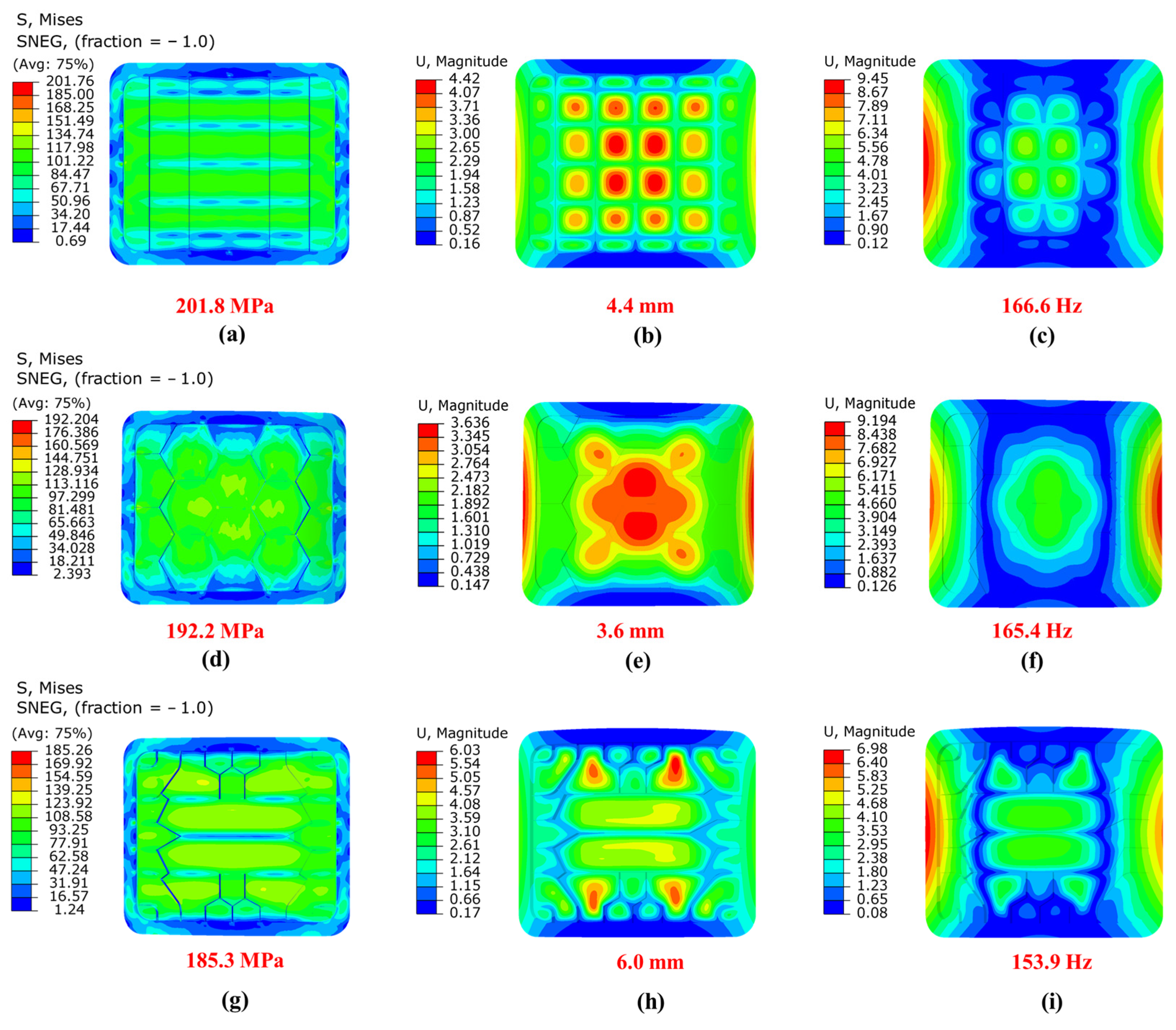
The results of the proposed method and the initial orthogrid or honeycomb design are compared in this section. The upper and lower bound of all parameters and the optimal result are listed in Table 2. The Mises stress field, displacement field, and first-order mode of the orthogrid design, honeycomb design, and optimal design of the overall model are shown in Figure 10. Similarly, the field results of the cabin door are shown in Figure 11. Comparison of the finite element analysis results between initial and optimal design of the cabin door. It can be noticed that the mass of the optimized cabin door and the stiffeners of the thin-wall structure is 15.24 kg, which is reduced by 52.21% compared to the traditional orthogrid design (31.89 kg) and reduced by 51.15% compared to the honeycomb design (31.2 kg). In addition, the optimization result meets the constraints of Mises stress, displacement, and fundamental frequency, which can verify the effectiveness and outstanding lightweight design ability of the proposed method.
4. Conclusions
To obtain innovative configurations in the preliminary design stage and perform efficient global optimization in the detailed design stage, a two-stage intelligent design method for the curved cabin door is proposed based on the mesh deformation method and the ES-CMA-ES algorithm. In the first stage, the topology optimization design of the cabin door is carried out, and the modeling and the feature extraction are carried out using the mesh deformation method to improve the modeling efficiency and geometric reconstruction accuracy. In the second stage, the ES-CMA-ES algorithm is employed to optimize the stiffener parameters of the cabin door and the surrounding thin-wall structure, aiming to obtain the lightweight design based on the premise of meeting the strength and stiffness requirements under various loading conditions. A spacecraft curved cabin door is taken as the example to verify the effectiveness of the proposed method, which shows that the proposed method can reduce the weight by 52% compared with the orthogrid design, demonstrating the huge application potential of the proposed method.
In the future work, automatic feature extraction and geometric reconstruction methods based on mesh deformation will be studied, aiming to improve the efficiency and robustness for more complex spacecraft structure.
Author Contributions
Conceptualization, Z.L. and Z.X.; methodology, T.G. and Z.L., formal analysis, T.G.; investigation, P.L., Z.X. and Z.L.; data curation, T G., Z.X. and Z.L.; writing—original draft preparation, T.G.; writing—review and editing, T.G., Z.X., P.L and K.T.; supervision, K.T.; funding acquisition, K.T. All authors have read and agreed to the published version of the manuscript.
Funding
National Natural Science Foundation of China (11902065); Fundamental Research Funds for the Central Universities (DUT21RC(3)013).
Institutional Review Board Statement
Not applicable.
Informed Consent Statement
Informed consent was obtained from all subjects involved in the study.
Data Availability Statement
Not applicable.
Conflicts of Interest
The authors declare no conflict of interest.
References
- Liu, S.; Zhang, B.; Wang, T.; Yi, Z.; Huang, N.; Cui, X.; Zhang, X.; Yu, J. Research on Sealing Assembly and Adjustment Method of Assembled Cabin Door of Space Station. J. Phys. Conf. Ser. 2022, 2338, 012013. [Google Scholar] [CrossRef]
- Zhao, W.; Sun, Y. Simulation Study on Pressure Relief of Cabin Door Under Explosive Load in Cabin. In Proceedings of the International Conference on Development and Application of Carbon Nanomaterials in Energetic Materials, Weihai, China, 19–20 August 2021. [Google Scholar]
- Zhu, J.; Zhang, W.H.; Xia, L. Topology optimization in aircraft and aerospace structures design. Arch. Comput. Methods Eng. 2016, 23, 595–622. [Google Scholar] [CrossRef]
- Yan, K.; Cheng, G.D.; Wang, B.P. Topology optimization of damping layers in shell structures subject to impact loads for minimum residual vibration. J. Sound Vib. 2018, 431, 226–247. [Google Scholar] [CrossRef]
- Fu, J.; Li, H.; Gao, L.; Xiao, M. Design of shell-infill structures by a multiscale level set topology optimization method. Comput. Struct. 2019, 212, 162–172. [Google Scholar] [CrossRef]
- Townsend, S.; Kim, H.A. A level set topology optimization method for the buckling of shell structures. Struct. Multidiscip. Optim. 2019, 60, 1783–1800. [Google Scholar] [CrossRef] [Green Version]
- Ji, J.; Ding, X.; Xiong, M. Optimal stiffener layout of plate/shell structures by bionic growth method. Comput. Struct. 2014, 135, 88–99. [Google Scholar] [CrossRef]
- Youn, S.K.; Park, S.H. A study on the shape extraction process in the structural topology optimization using homogenized material. Comput. Struct. 1997, 62, 527–538. [Google Scholar] [CrossRef]
- Wang, B.; Zhou, Y.; Tian, K.; Wang, G. Novel implementation of extrusion constraint in topology optimization by Helmholtz-type anisotropic filter. Struct. Multidiscip. Optim. 2020, 62, 2091–2100. [Google Scholar] [CrossRef]
- Zhou, M.; Fleury, R.; Shyy, Y.K.; Thomas, H.; Brennan, J. Progress in topology optimization with manufacturing constraints. In Proceedings of the 9th AIAA/ISSMO Symposium on Multidisciplinary Analysis and Optimization, Atlanta, America, 4–6 September 2002. [Google Scholar]
- Zhou, M.; Shyy, Y.K.; Thomas, H.L. Checkerboard and Minimum Member Size Control in Topology Optimization. Struct. Multidiscip. Optim. 2001, 21, 152–158. [Google Scholar] [CrossRef]
- Tian, K.; Huang, L.; Yang, M.; Chen, Y.; Hao, P.; Wang, B. Concurrent numerical implementation of vibration correlation technique for fast buckling load prediction of cylindrical shells under combined loading conditions. Eng. Comput. 2022, 38, 3269–3281. [Google Scholar] [CrossRef]
- Ferrari, F.; Sigmund, O. Revisiting topology optimization with buckling constraints. Struct. Multidiscip. Optim. 2019, 59, 1401–1415. [Google Scholar] [CrossRef] [Green Version]
- Ferrari, F.; Sigmund, O. Towards solving large-scale topology optimization problems with buckling constraints at the cost of linear analyses. Comput. Methods Appl. Mech. Eng. 2020, 363, 112911. [Google Scholar] [CrossRef] [Green Version]
- Amroune, A.; Cuillière, J.C.; François, V. Automated lofting-based reconstruction of CAD models from 3D topology optimization results. Comput. Aided Des. 2022, 145, 103183. [Google Scholar] [CrossRef]
- Fei, C.; Wen, J.; Han, L.; Huang, B.; Yan, C. Optimizable Image Segmentation Method with Superpixels and Feature Migration for Aerospace Structures. Aerospace 2022, 9, 465. [Google Scholar] [CrossRef]
- Belardo, M.; Marano, A.; Beretta, J.; Diodati, G.; Graziano, M.; Capasso, M.; Ariola, P.; Orlando, S.; Di Caprio, F.; Paletta, N.; et al. Wing structure of the Next-Generation Civil Tiltrotor: From concept to preliminary design. Aerospace 2021, 8, 102. [Google Scholar] [CrossRef]
- Bouzarkouna, Z.; Auger, A.; Ding, D.Y. Investigating the local-meta-model CMA-ES for large population sizes. In Proceedings of the European Conference on the Applications of Evolutionary Computation, Istanbul, Turkey, 7–9 April 2010. [Google Scholar] [CrossRef] [Green Version]
- Wang, H.; Jin, Y.; Jansen, J.O. Data-driven surrogate-assisted multiobjective evolutionary optimization of a trauma system. IEEE Trans. Evol. Comput. 2016, 20, 939–952. [Google Scholar] [CrossRef] [Green Version]
- Jin, Y.; Wang, H.; Chugh, T.; Guo, D.; Miettinen, K. Data-driven evolutionary optimization: An overview and case studies. IEEE Trans. Evol. Comput. 2018, 23, 442–458. [Google Scholar] [CrossRef]
- Li, H.; Li, Z.; Cheng, Z.; Zhou, Z.; Wang, G.; Wang, B.; Tian, K. A data-driven modelling and optimization framework for variable-thickness integrally stiffened shells. Aerosp. Sci. Technol. 2022, 129, 107839. [Google Scholar] [CrossRef]
- Huang, L.; Li, H.; Zheng, K.; Tian, K.; Wang, B. Shape optimization method for axisymmetric disks based on mesh deformation and smoothing approaches. Mech. Adv. Mater. Struct. 2022, 1–24. [Google Scholar] [CrossRef]
- Tian, K.; Li, H.; Huang, L.; Huang, H.; Zhao, H.; Wang, B. Data-driven modelling and optimization of stiffeners on undevelopable curved surfaces. Struct. Multidiscip. Optim. 2020, 62, 3249–3269. [Google Scholar] [CrossRef]
- Li, Z.; Tian, K.; Li, H.; Shi, Y.; Wang, B. A competitive variable-fidelity surrogate-assisted CMA-ES algorithm using data mining techniques. Aerosp. Sci. Technol. 2021, 119, 107084. [Google Scholar] [CrossRef]
- Li, Z.; Gao, T.; Tian, K.; Wang, B. Elite-driven surrogate-assisted CMA-ES algorithm by improved lower confidence bound method. Eng. Comput. 2022, 1–24. [Google Scholar] [CrossRef]
- Hansen, N.; Ostermeier, A. Adapting arbitrary normal mutation distributions in evolution strategies: The covariance matrix adaptation. In Proceedings of the IEEE International Conference on Evolutionary Computation, Nagoya, Japan, 20–22 May 1996; pp. 312–317. [Google Scholar] [CrossRef]
- Pitra, Z.; Bajer, L.; Repický, J.; Holeňa, M. Overview of surrogate-model versions of covariance matrix adaptation evolution strategy. In Proceedings of the Genetic and Evolutionary Computation Conference Companion, Berlin, Germany, 15–19 July 2017; pp. 1622–1629. [Google Scholar] [CrossRef]
- Bajer, L.; Pitra, Z.; Repický, J.; Holeňa, M. Gaussian process surrogate models for the CMA evolution strategy. Evol. Comput. 2019, 27, 665–697. [Google Scholar] [CrossRef]
- Liu, Q.; Jin, Y.; Heiderich, M.; Rodemann, T. Surrogate-assisted evolutionary optimization of expensive many-objective irregular problems. Knowl. Based Syst. 2022, 240, 108197. [Google Scholar] [CrossRef]
- Fuerle, F.; Sienz, J. Formulation of the Audze–Eglais uniform Latin hypercube design of experiments for constrained design spaces. Adv. Eng. Softw. 2011, 42, 680–689. [Google Scholar] [CrossRef]
- Kang, F.; Xu, Q.; Li, J. Slope reliability analysis using surrogate models via new support vector machines with swarm intelligence. Appl. Math. Model. 2016, 40, 6105–6120. [Google Scholar] [CrossRef]
- Gill, P.E.; Murray, W.; Saunders, M.A. SNOPT: An SQP algorithm for large-scale constrained optimization. SIAM Rev. 2005, 47, 99–131. [Google Scholar] [CrossRef]
- Boggs, P.T.; Tolle, J.W. Sequential quadratic programming. Acta Numer. 1995, 4, 1–51. [Google Scholar] [CrossRef] [Green Version]
- Tian, K.; Lai, P.; Sun, Y.; Sun, W.; Cheng, Z.; Wang, B. Efficient buckling analysis and optimization method for rotationally periodic stiffened shells accelerated by Bloch wave method. Eng. Struct. 2022, 276, 115395. [Google Scholar] [CrossRef]
- Li, Z.; Zhang, S.; Li, H.; Tian, K.; Cheng, Z.; Chen, Y.; Wang, B. On-line transfer learning for multi-fidelity data fusion with ensemble of deep neural networks. Adv. Eng. Inform. 2022, 53, 101689. [Google Scholar] [CrossRef]
- Tian, K.; Li, Z.; Zhang, J.; Huang, L.; Wang, B. Transfer learning based variable-fidelity surrogate model for shell buckling prediction. Compos. Struct. 2021, 273, 114285. [Google Scholar] [CrossRef]
Figure 1.
Schematic diagrams of the spacecraft. (a) Spacecraft thin-wall structure (from https://www.flickr.com/photos/nasaorion/ (accessed on 12 October 2020)); (b) Spacecraft cabin door (from http://www.spacechina.com/n25/n2014789/n2888836/c2929321/content.html (accessed on 29 May 2020)).
Figure 1.
Schematic diagrams of the spacecraft. (a) Spacecraft thin-wall structure (from https://www.flickr.com/photos/nasaorion/ (accessed on 12 October 2020)); (b) Spacecraft cabin door (from http://www.spacechina.com/n25/n2014789/n2888836/c2929321/content.html (accessed on 29 May 2020)).
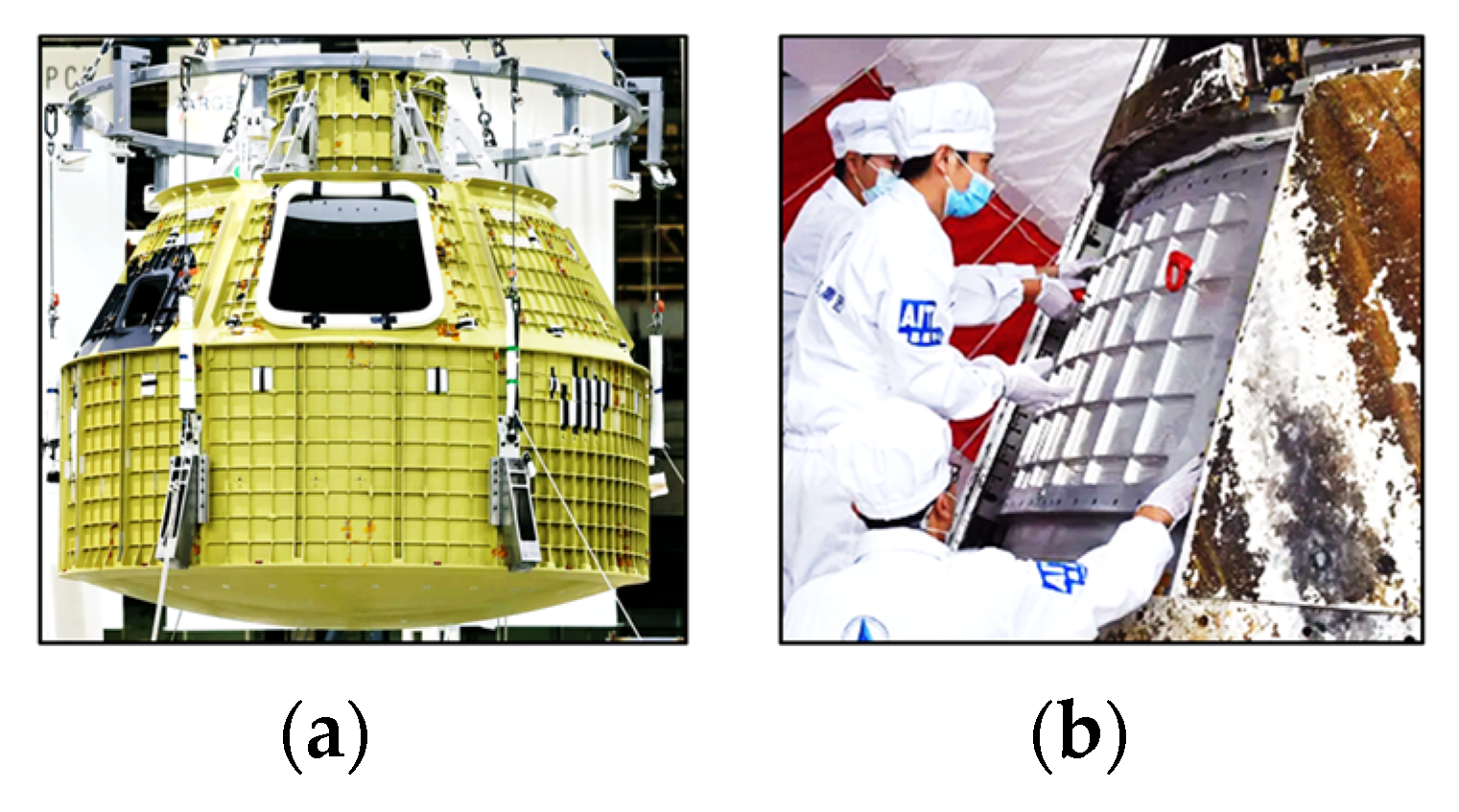
Figure 2.
Schematic diagram of training RBF neural network.

Figure 3.
Flow chart of intelligent layout design framework for curved cabin door.
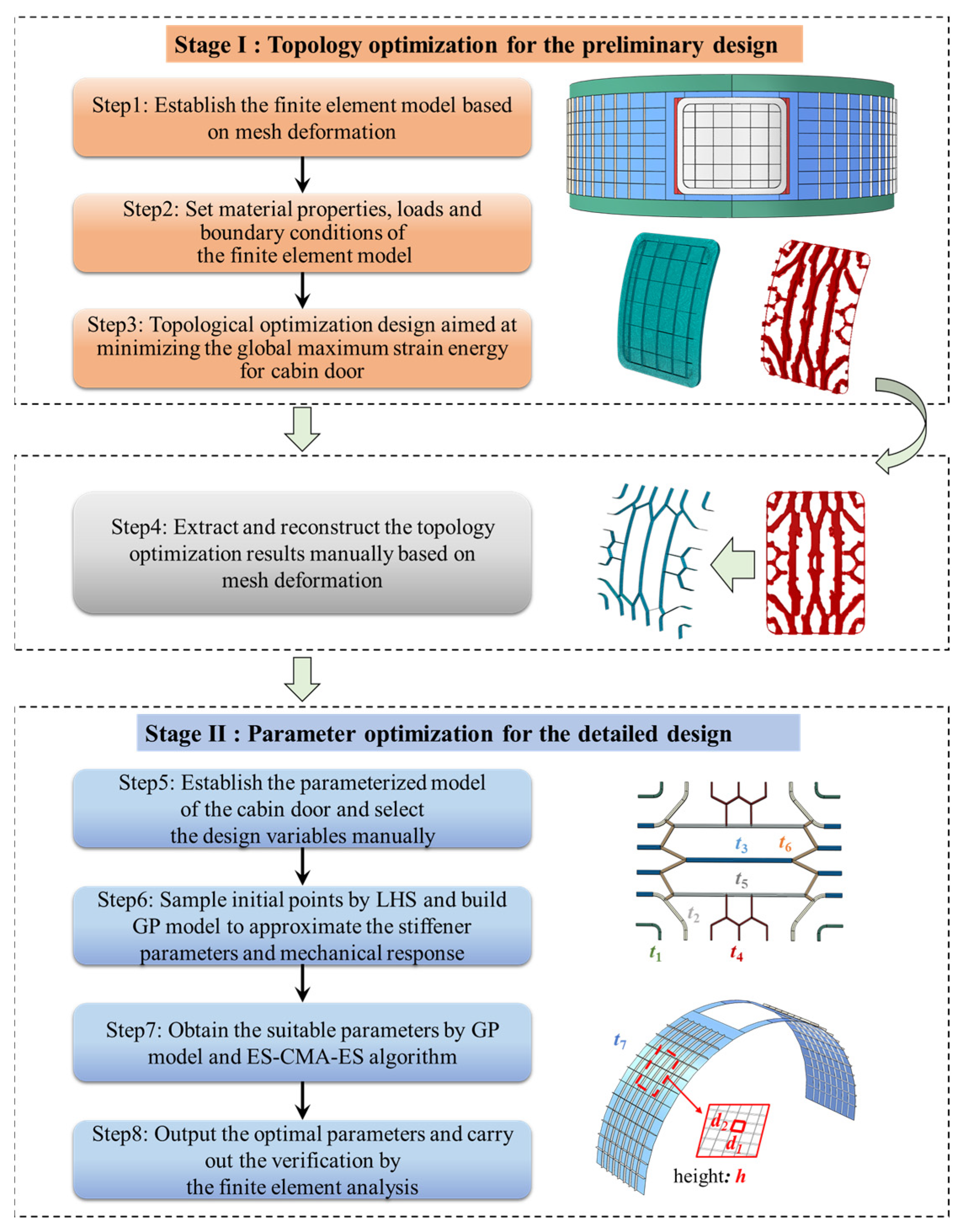
Figure 4.
Schematic diagram of the initial design of the cabin door and thin-wall structure.
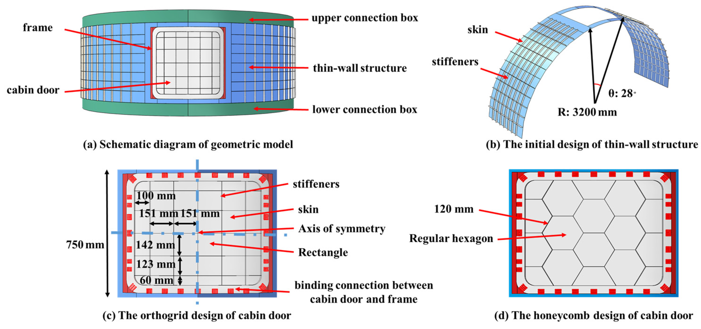
Figure 5.
Schematic diagram for modeling of stiffeners and curved cabin door by mesh deformation method.
Figure 5.
Schematic diagram for modeling of stiffeners and curved cabin door by mesh deformation method.
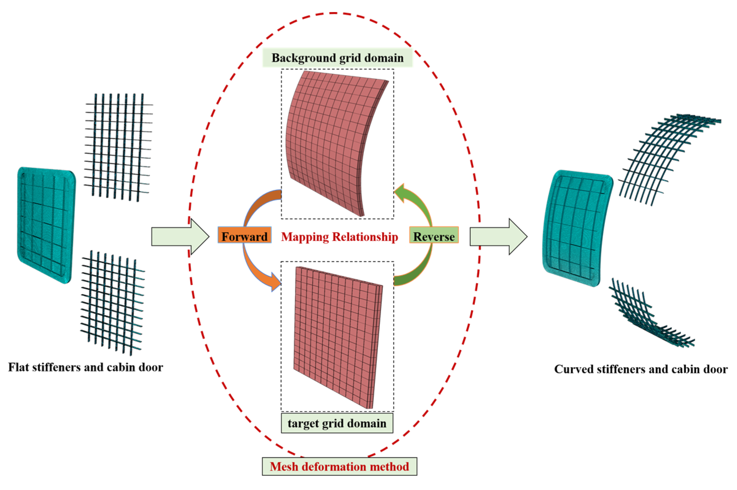
Figure 6.
Schematic Diagram of Stamping Constraint.
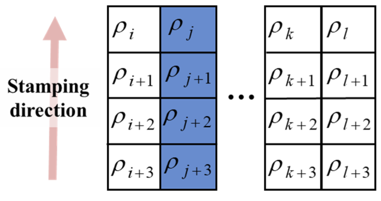
Figure 7.
Iteration histories of TO for cabin door.
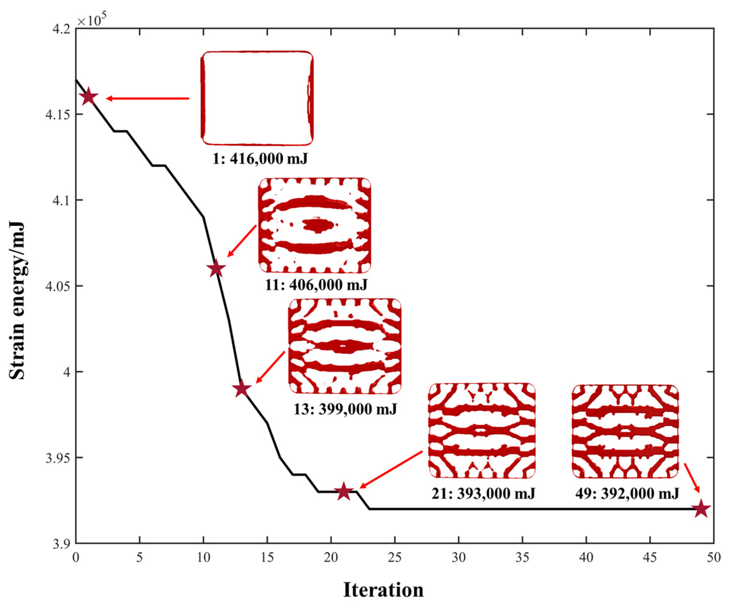
Figure 8.
Schematic diagram of feature extraction and geometric reconstruction process.
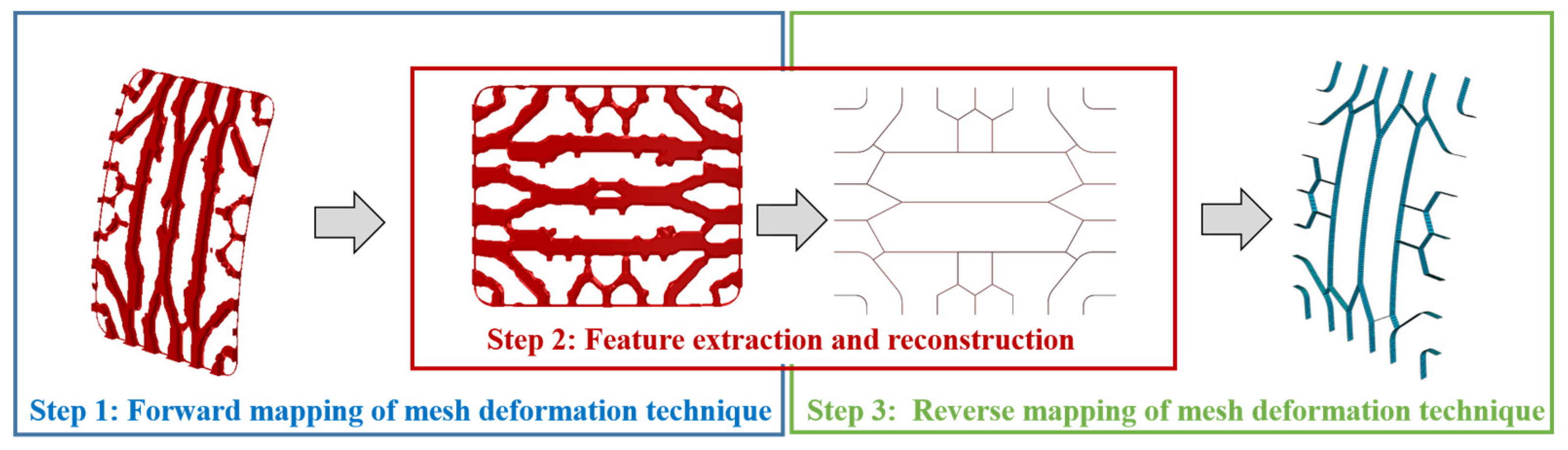
Figure 9.
Iteration histories of parameter optimization based on ES-CMA-ES.
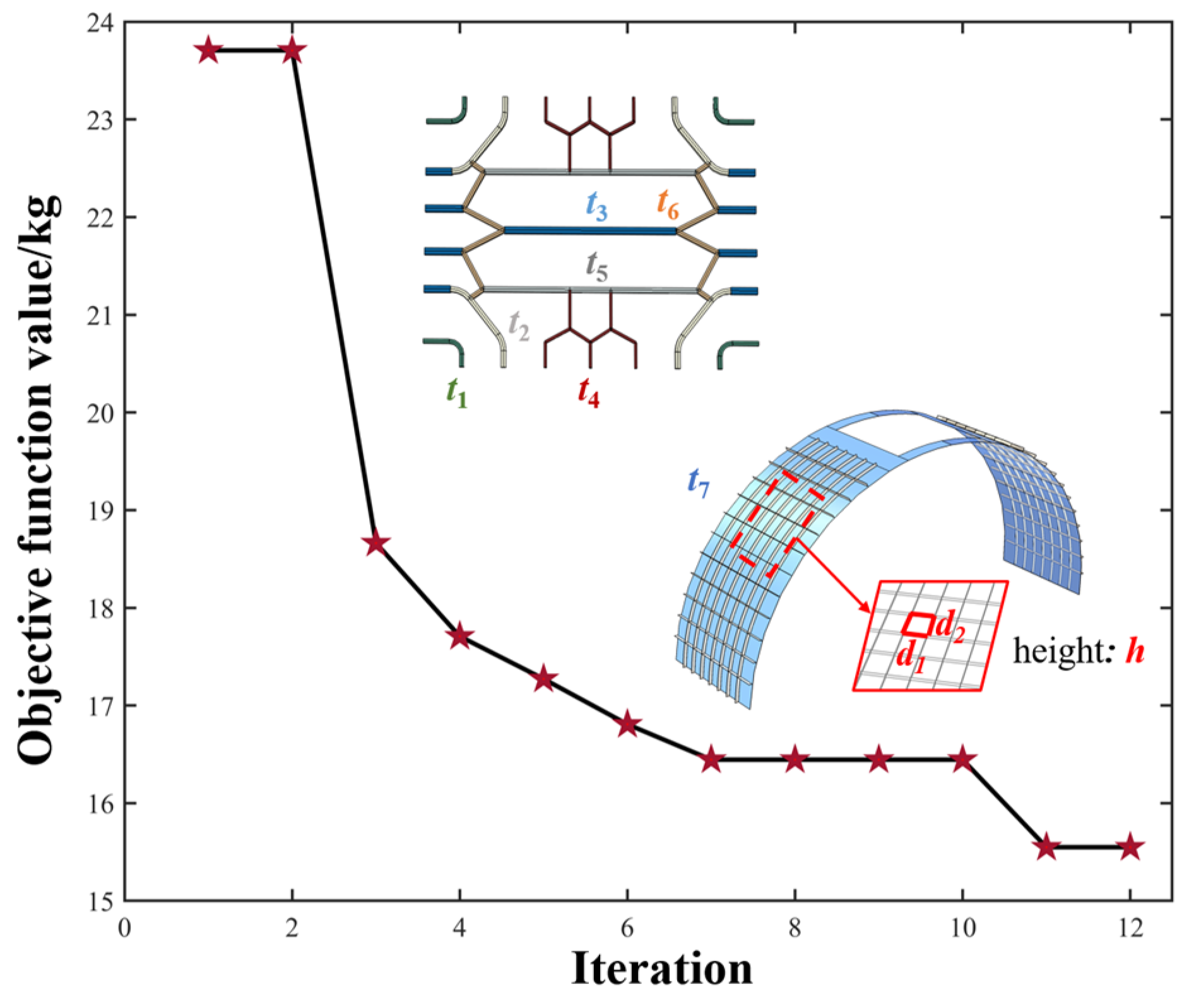
Figure 10.
Comparison of the finite element analysis results between initial and optimal design of the overall model. (a) Mises stress field of the overall model in orthogrid design. (b) Displacement field of the overall model in orthogrid design. (c) First order modal shape of the overall model in orthogrid design. (d) Mises stress field of the overall model in honeycomb design. (e) Displacement field of the overall model in honeycomb design. (f) First order modal shape of the overall model in honeycomb design. (g) Mises stress field of the overall model in optimal design. (h) Displacement field of the overall model in optimal design. (i) First order modal shape of the coverall model in optimal design.
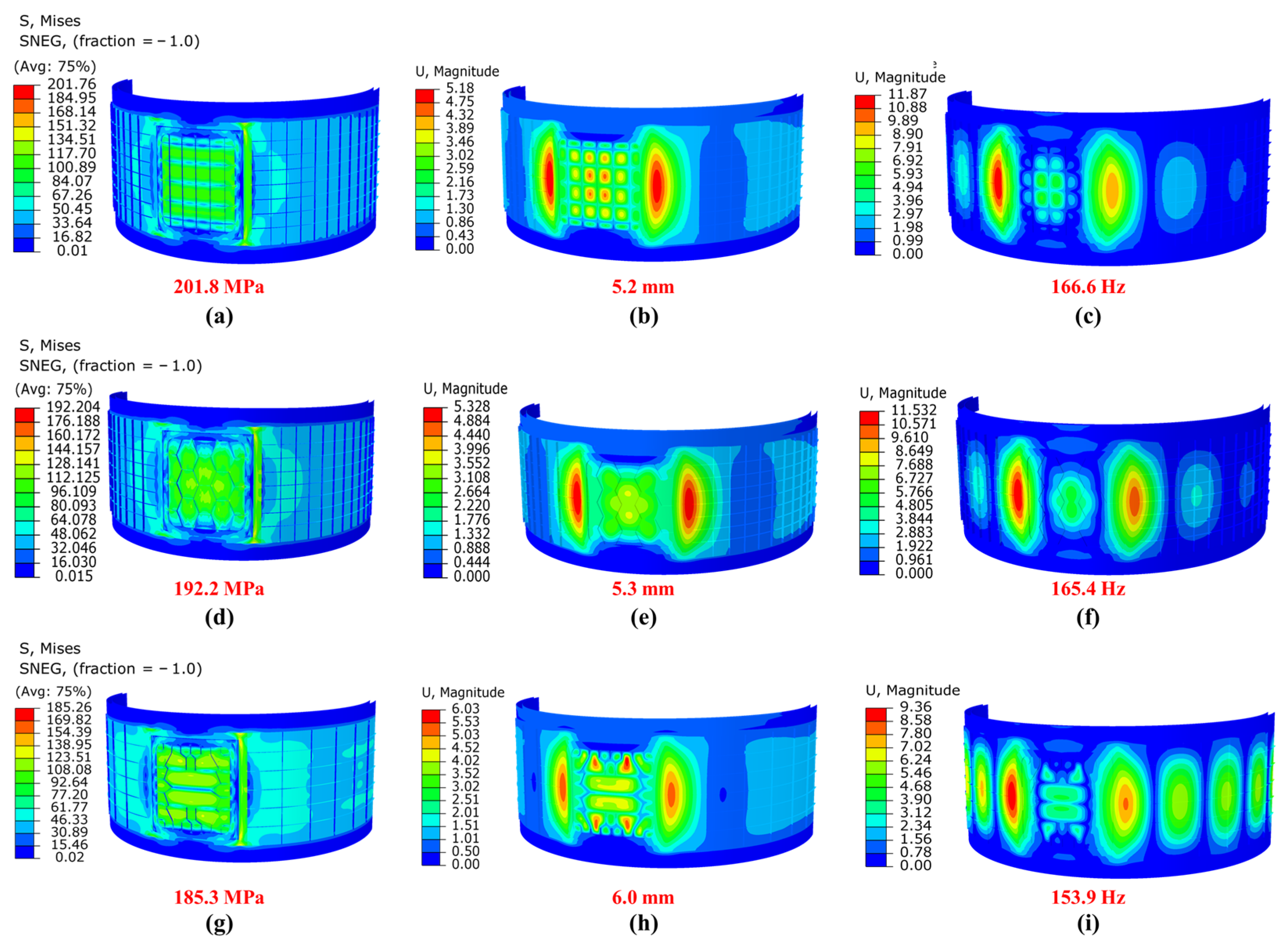
Figure 11.
Comparison of the finite element analysis results between initial and optimal design of the cabin door. (a) Mises stress field of the cabin door in orthogrid design. (b) Displacement field of the cabin door in orthogrid design. (c) First order modal shape of the cabin door in orthogrid design. (d) Mises stress field of the cabin door in honeycomb design. (e) Displacement field of the cabin door in honeycomb design. (f) First order modal shape of the cabin door in honeycomb design. (g) Mises stress field of the cabin door in optimal design. (h) Displacement field of the cabin door in optimal design. (i) First order modal shape of the cabin door in optimal design.

Table 1.
The main parameters of cabin door and its surrounding thin-wall structure.
| E [GPa] | v | ρ [g/cm3] | R [mm] | θ [°] | H1 [mm] | H2 [mm] | T1 [mm] | h1 [mm] | T2 [mm] |
|---|---|---|---|---|---|---|---|---|---|
| 67 | 0.3 | 2.700 | 3200 | 28 | 850 | 750 | 2 | 18 | 5 |
Table 2.
The upper and lower bounds of parameters and their optimal result.
| Design Variable | Lower Bound | Upper Bound | Orthogrid Design | Honeycomb Design | Optimal Design |
|---|---|---|---|---|---|
| d1 [mm] | 70.0 | 140.0 | 100.0 | 100.0 | 140.0 |
| d2 [mm] | 50.0 | 200.0 | 100.0 | 100.0 | 200.0 |
| h [mm] | 5.0 | 35.0 | 25.0 | 25.0 | 19.1 |
| t1 [mm] | 2.0 | 10.0 | 6.0 | 6.0 | 2.0 |
| t2 [mm] | 2.0 | 10.0 | — | — | 2.0 |
| t3 [mm] | 2.0 | 10.0 | — | — | 9.8 |
| t4 [mm] | 2.0 | 10.0 | — | — | 6.0 |
| t5 [mm] | 2.0 | 10.0 | — | — | 2.1 |
| t6 [mm] | 2.0 | 10.0 | — | — | 3.8 |
| t7 [mm] | 2.0 | 10.0 | 6.0 | 6.0 | 2.0 |
| mass [kg] | — | — | 31.9 | 31.2 | 15.2 |
| Mises stress [MPa] | — | — | 201.8 | 192.2 | 185.3 |
| displacement [mm] | — | — | 5.2 | 5.3 | 6.0 |
| frequency [Hz] | — | — | 166.6 | 165.4 | 153.9 |
Disclaimer/Publisher’s Note: The statements, opinions and data contained in all publications are solely those of the individual author(s) and contributor(s) and not of MDPI and/or the editor(s). MDPI and/or the editor(s) disclaim responsibility for any injury to people or property resulting from any ideas, methods, instructions or products referred to in the content. |
© 2023 by the authors. Licensee MDPI, Basel, Switzerland. This article is an open access article distributed under the terms and conditions of the Creative Commons Attribution (CC BY) license (https://creativecommons.org/licenses/by/4.0/).
Share and Cite
MDPI and ACS Style
Gao, T.; Xu, Z.; Li, Z.; Liu, P.; Tian, K. Two-Stage Intelligent Layout Design of Curved Cabin Door. Aerospace 2023, 10, 89. https://doi.org/10.3390/aerospace10010089
AMA Style
Gao T, Xu Z, Li Z, Liu P, Tian K. Two-Stage Intelligent Layout Design of Curved Cabin Door. Aerospace. 2023; 10(1):89. https://doi.org/10.3390/aerospace10010089
Chicago/Turabian StyleGao, Tianhe, Ziyu Xu, Zengcong Li, Pei Liu, and Kuo Tian. 2023. "Two-Stage Intelligent Layout Design of Curved Cabin Door" Aerospace 10, no. 1: 89. https://doi.org/10.3390/aerospace10010089
Note that from the first issue of 2016, this journal uses article numbers instead of page numbers. See further details here.