
Preliminary Analysis of the Stability and Controllability of a Box-Wing Aircraft Configuration


Department of Civil and Industrial Engineering, University of Pisa, Via G. Caruso 8, 56122 Pisa, Italy
*
Author to whom correspondence should be addressed.
Aerospace 2023, 10(10), 874; https://doi.org/10.3390/aerospace10100874
Submission received: 5 September 2023
/
Revised: 29 September 2023
/
Accepted: 6 October 2023
/
Published: 8 October 2023
(This article belongs to the Special Issue Aircraft Modeling, Simulation and Control II)
Abstract
:This paper presents a study on the aeromechanical characteristics of a box-wing aircraft configuration with a focus on stability, controllability, and the impact of aeromechanical constraints on the lifting system conceptual design. In the last decade, the box-wing concept has been the subject of several investigations in the aeronautical scientific community, as it has the potential to improve classic aerodynamic performance, aiming at reducing fuel consumption per unit of payload transported, and thus contributing to a reduction in aviation greenhouse emissions. This study characterises the aeromechanical features of a box-wing aircraft, with a specific focus on the correlations between the aeromechanical constraints and the (main) aircraft design parameters. The proposed approach provides specific insights into the aeromechanical characteristics of the box-wing concept, both in the longitudinal and lateral plane, which are useful to define some overall design criteria generally applicable when dealing with the conceptual design of such an unconventional aircraft configuration.
1. Introduction
The study of advanced configurations for transport aircraft is of great interest in the aeronautical scientific community and, among these, the box-wing concept has been the subject of several investigations for a long time [1,2,3]; this lifting architecture is characterised by two horizontal wings connected by vertical tip-wings. Such a particular lifting architecture appears as a potential improvement in the state-of-the-art in terms of both aerodynamic performance and aircraft loading capability [4,5,6,7,8,9]. In general, a box-wing aircraft could introduce substantial benefits in terms of reductions in fuel consumption per unit of payload mass transported [8], thus making a beneficial contribution to a reduction in aviation greenhouse emissions [10]. This aspect is of fundamental interest within today’s scientific community [11,12,13,14], so, the study and development of this specific advanced configuration are always in progress to increase its degree of knowledge and level of technological integration.
To date, there are several published studies that compose the framework of knowledge around this lifting architecture, as now briefly summarised. The concept of the box-wing as a lifting system with minimum induced drag was introduced, from a theoretical point of view, by Ludwig Prandtl about one century ago in his fundamental study on multiplanes [15], in which it is supposed that the lifting system with minimum induced drag (the lift and span being the same) is a box-wing in frontal view, named the Best Wing System (BWS), with an optimal lift distribution. This specific hypothesis was later confirmed analytically in [16], where the optimal lift distribution was determined using classical variational mathematical techniques, which was identified as a typical elliptical lift distribution summed with a constant contribution on each horizontal lifting surface and a butterfly distribution on the vertical wings; see the left part of Figure 1. In support of these theoretical studies, insights into the minimum induced drag of multiplanes, biplanes, and box-wing aircraft are proposed in [17,18,19,20], where the non-uniqueness theorem of the optimal solution, in terms of the lift distribution of a closed lifting system, is analysed and discussed in depth. In this context, the scientific literature [17,18,19,20] indicates that there are infinite equivalent optimal solutions to the problem of the minimum induced drag of a box-wing configuration, which can be obtained by adding an arbitrary constant to the optimal circulation of each horizontal lifting surface. This point is highlighted in Figure 1, in which are reported box-wings with different lift distributions but with the same optimal aerodynamic efficiency ratio ε defined, according to [17], as the ratio between the aerodynamic efficiency of a generic lifting system and the corresponding efficiency of a reference cantilevered wing with same span and lift, both evaluated in their optimal conditions.
This result has a key impact on the design of such lifting systems, as it enables the sizing of box-wing configurations with different loading on the two horizontal wings without deviating from the classical optimal solution theorised by Prandtl [15]. A further fundamental result on the optimal design of the BWS is provided by Munk’s theorem [21], which states that the induced drag of the optimal lift distribution remains the same even if the two horizontal wings are distanced horizontally or are swept. The non-uniqueness theorem of the optimal solution, together with Munk’s theorem, opens the field to the study of the longitudinal stability of a box-wing aircraft, offering a wide range of design space and multiple viable solutions.
The study proposed in this paper is placed specifically in this context, aiming to characterise in a general way (as possible) the aeromechanical characteristics of a box-wing aircraft, with a specific focus on stability, controllability, and the relation that the aeromechanical constraints have with the main design parameters of the lifting system, starting from the conceptual stages of design. In fact, the study and characterisation of aeromechanical features is a fundamental topic in aircraft development. For example, significant studies related to more conventional aircraft configurations are proposed in [22,23], regarding aspects of flight mechanics assessment in the overall design process, and in [24,25], where the focus is posed on directional stability. In general, the correlations that aeromechanical constraints introduce into the design development of conventional aircraft are well-established [26,27,28]. On the other hand, for aircraft with non-conventional lifting architecture, such as box-wing configurations, such correlations may need generalisations that differ from the established findings known for classical tube-and-wing aircraft, and this study aims to offer such results at a conceptual level. The stability and control investigation of advanced and unconventional aircraft configuration is hence a generally relevant topic, see [29,30,31,32]. For example, for blended wing body configurations [33,34,35], a comprehensive study on the stability characteristics is reported in [36]. In the recent literature, preliminary studies that have addressed the aeromechanical conceptual study of a box-wing aircraft generally refer to multidisciplinary frameworks that integrate stability and controllability aspects into a broader performance assessment context [37,38,39,40,41,42]. Studies that focus more specifically on the effects of the introduction of aeromechanical constraints on the design of the box-wing lifting system, on the other hand, are few, and a critical analysis of these is briefly proposed in the following.
A very interesting initial study of the effects of stability and controllability constraints on box-wing performance is offered in [43], where the possibility of a conflict between aerodynamic efficiency and longitudinal static stability is first postulated. The approach used in [43] is based on very simplified analytical models to describe aeromechanical constraints, and the aerodynamics is addressed with the simplified models related to the optimal lift of biplanes [15]. The results obtained by [43] show that, in order to obtain stable box-wing aircraft in the longitudinal plane, it is necessary for the front wing to have a sufficiently higher lift coefficient than the rear one. Based on this specific result, since there is no longer equivalence between the lift distribution on the front and rear wings, ref. [43] states that the configuration deviates from the optimal lift distribution so that penalties in terms of induced drag are introduced. These important results indicate a first hint of the effect of stability constraints on the aerodynamic efficiency of a box-wing configuration. However, the use of an oversimplified aerodynamic approach leads to an inaccurate formalisation of the aerodynamic design problem. In fact, the assumption is made that the optimal lift of a box-wing configuration has only one solution, namely, that of the BWS proposed by Prandtl in [15], while the theorems stated in [17,18,19,20] demonstrate the non-uniqueness of the optimal solution. This important limitation is also pointed out in [43], leaving the more general characterisation of the problem to future developments. In addition, a further limitation to the generalisation of the results proposed in [43] lies in the stringent assumption of sizing the two box-wing horizontal lifting surfaces of equal reference area, an assumption also introduced in the subsequent multidisciplinary study detailed in [38]. Such a particular condition is, in fact, not necessary for the proper design development of box-wing aircraft, and actually, the difference in the reference surfaces of the two wings can serve as a very important lever in the design towards stability, as discussed later in this paper.
Other works that focused on the analysis of the stability of box-wing aircraft are [44,45], where an attempt to characterise the correlations between stability and performance is proposed using a multidisciplinary design approach, relying on simplified analytical handling of the aerodynamic design problem. However, the use of overly stringent simplifications and assumptions does not provide a generalisation of the obtained outcomes but allows only for results specific to the considered case studies. In this context, a (significantly) stringent constraint on the coincidence of the longitudinal position of the front and rear wingtips links two parameters that are crucial regarding stability, namely, the wing sweep angles and their relative longitudinal position, thus providing outcomes purely specific to this (rather unusual) geometric arrangement. Accordingly, the most important result provided in [44] is that increasing the distance between the two wings leads to the best aerodynamic performance, as larger horizontal wings stagger results in a larger sweep angle, thereby reducing the wave drag. This specific conclusion can in no way lead to the general deduction that it is necessary to have as much horizontal spacing as possible between the two horizontal wings of the boxed configuration, which does not turn out to be generally true. Moreover, this outcome is only related to the relationship between the wing sweep angle and the wave drag, and so only applicable to aircraft operating in a transonic regime. In addition, no general trends can be extracted regarding the front and rear wing reference surface ratio, as in [44], it is stated that the optimal configuration is one with equal surfaces, while it is pointed out that this specific condition leads to unstable configurations, and that reductions in the front wing surface are necessary to satisfy classical aeromechanical constraints. What can be inferred from a general point of view, is that penalties in aerodynamic efficiency are to be considered when stability and controllability constraints are introduced in the aircraft preliminary design. In general, therefore, such research provides interesting simplified analytical models for introducing downwash effects on the stability of a box-wing configuration. However, the application of this approach does not lead to generalisable studies that correlate stability constraints to major (aircraft) design parameters. The other studies in the recent literature, involving the analysis of stability and controllability in the longitudinal plane of box-wing aircraft, place these aspects in multidisciplinary design and performance analysis contexts and thus do not provide direct insights into the interdependence between aeromechanical constraints and design parameters (or aircraft performance). Such interesting works are, however, of relevance in the context of this study, as they provide useful insights into the overall aeromechanical performance characteristics of box-wing configurations, including medium-range [8,46], regional [47,48], or small-scale [49] aircraft.
Regarding controllability and manoeuvrability, some studies have paved the way for the definition of movable surfaces layouts that, in a box-wing configuration, differ from the classical solutions used in a conventional aircraft. These models are mainly discussed in [50,51] and point out that the placement of control surfaces on both wings can result in performance benefits or new control options. For example, pairs of elevators placed at the root of both wings and activated in counter-phase can minimise the negative lift variation associated with the pitch-up moment typical of wing-tail aircraft, thus increasing safety for manoeuvres close to the ground (e.g., in the case of missed approach). As well, the proper design, the control strategy, and the placement on the two wings of multiple movable surfaces may enable new control techniques, such as pure-pitch or direct-lift [52]. Finally, regarding aspects related to stability and controllability in low speed, that is, for aircraft with high-lift systems deployed, or those related to directional stability, limited information is found in the literature, and no studies have been focused on the influence of considering these important aspects in the overall design of a box-wing aircraft.
Within the previously outlined context, this work aims to provide both a conceptual investigation of the aeromechanical features of aircraft with box-wing lifting architecture and to identify the correlations and interdependencies that may exist between stability and controllability constraints and the main design variables and/or performance parameters. To achieve this goal, the design space of box-wing aircraft is extensively explored by evaluating the aeromechanical properties using potential Vortex Lattice Method (VLM) solvers, while verifications with higher fidelity techniques, such as CFD simulations, are also considered in some cases. In particular, the aeromechanical analysis presented in this paper, aiming to be as general as possible, is intended to: (i) introduce longitudinal stability and controllability constraints into the conceptual design of the lifting system and evaluate their overall effects on design and performance; (ii) evaluate the potential for minimising trim drag throughout the operating mission; (iii) introduce constraints related to the aircraft stable stall; (iv) asses low-speed performance (i.e., speed and attitude with high-lift systems deployed, as for the approach flight condition) and evaluate the effect of high-lift systems on the trim in the longitudinal plane; and (v) characterise directional stability and identify any critical issues in this regard. From the synthesis of the previous points, therefore, it is possible to finally derive a set of general criteria for the conceptual design of box-wing lifting systems, which consider stability and control constraints from the earliest design phases, correlating architectural parameters with classical aeromechanical properties.
The paper is structured as follows: in Section 2, the methodology used to perform the aeromechanical analysis is outlined, while Section 3 provides a general description of the lifting system design criteria for a box-wing architecture. In Section 4, the focus is given to the trim in low-speed conditions, considering flapped lifting surfaces, and in Section 5, a general description of the lateral stability design parameters is provided. Finally, Section 6 summarises the aeromechanical-related design criteria, and in Section 7, the conclusions are given.
2. Methodology Description
The study of the aeromechanical features of a commercial aircraft can be approached on different levels with the use of tools and methods of different fidelity [53,54,55,56]. Depending on the study to be carried out, and on the maturity of the design process, there are appropriate choices that allow for optimising the trade-off between the reliability of the numerical results and the computational cost/time [57,58,59,60,61]. In this context, Table 1 briefly summarises the characteristics of a set of different fidelity methods that can be used to characterise the aerodynamic derivatives of typical commercial aircraft.
In Table 1, a column called ‘Reliability of results’ has not been included because this aspect cannot be generally defined, and it depends on the specific case study, the reference operating conditions, the quality of the modelling, the expertise of the modeller/operator, and other specific aspects. In general, what can be said is whether a specific model is reliable if validations related to a case study on the object have been previously carried out. In the specific case of a box-wing aircraft aeromechanical analysis, we refer to previous validation studies reassumed in [78], from which it can be deduced that: (i) potential VLM models are adequate for assessing aeromechanical trends in the longitudinal plane if aerodynamic derivatives with respect to α are taken into account; (ii) the results obtained using VLM may not at all times be accurate in absolute terms, but generalisable considerations are nonetheless permitted at the conceptual exploration stage; and (iii) VLM models may be completely unreliable for the estimation of lateral-directional derivatives, so that higher fidelity models are suitable for an appropriate characterisation of these aspects.
For these reasons, in this work, an exploration of the box-wing aircraft longitudinal aeromechanical characteristics is conducted using VLM-based code called AVL, which is integrated into the multidisciplinary design, analysis, and optimization (MDAO) tool described in [79,80]; see Section 3. In particular, MDAO-based methodologies are widely used in aircraft design research [81,82,83,84], as they can be powerful frameworks for the conceptual investigation of novel advanced configurations [85,86,87].
In this study, the AVL code was used as an aerodynamic solver within a constrained optimisation procedure, specifically developed in MATLAB and properly described in Section 3.1, with the purpose of steering the design process of the box-wing planform, allowing evaluation of its aeromechanical derivatives and aerodynamic performance in the longitudinal plane; the AVL model of a generic box-wing lifting configuration is proposed in the left figure of Figure 2. The automatic design process implemented with numerical optimisation, together with the efficiency of the AVL solver in terms of computational time, has enabled the design and performance analysis of thousands of box-wing configurations. This has, therefore, allowed a wide-ranging analysis of the correlations between aeromechanical constraints and design parameters at the conceptual stage of the design process.
On the other hand, due to the known limitations of lower fidelity models for a preliminary investigation of directional stability, CFD simulations have been adopted to assess the lateral aerodynamic derivatives. Specifically, steady RANS models have been performed using ANSYS Fluent commercial code [88]; the turbulence model adopted is the k-ε realizable, and compressibility effects have not been taken into account, as a stability assessment is performed at low speed. An example of the output of a generic RANS simulation of a box-wing aircraft is represented in the right part of Figure 2, where the map of the distribution on the aircraft surface is depicted.
In this context, Table 2 shows some of the main characteristics of the two different aerodynamic models. In particular, the comparison shows that RANS simulations require much more detailed pre-processing involving 3D modelling of the aircraft by means of CAD software, more advanced hardware, as well as considerably more computational time, thus providing the capability of evaluating far fewer configurations per unit of time than the corresponding VLM.
3. Lifting System Planform Design
This section discusses in detail the general aeromechanical analysis of a box-wing configuration in the longitudinal plane. The aim of this section is to investigate the relationship that architectural properties of the box-wing aircraft have with aeromechanical constraints, both in terms of stability and controllability and safety and aerodynamic performance. In particular, Section 3.1 examines the influence of aeromechanical constraints on the design of the box-wing lifting system, Section 3.2 introduces additional constraints related to the stability of the stall, and finally, Section 3.3 describes the problem of trim drag minimisation.
3.1. Longitudinal Stability and Pitch Trim
The design of a transport aircraft lifting system must fulfil several interdisciplinary requirements, involving overall aerodynamic and aeromechanical performance, as well as geometric and functional requirements associated with the wing system. Specifically, a good design of a lifting system should lead to an aircraft with excellent aerodynamic efficiency (in terms of the value of the lift-to-drag ratio), which is stable and controllable, while complying with geometric and size constraints imposed by the airport infrastructure. An aircraft with a conventional lifting architecture allocates the lifting functions to the main wing, while the stability and controllability requirements are met with the proper design of the wing–tail configuration. For a box-wing aircraft, on the other hand, the lifting and aeromechanical functions in the longitudinal plane are simultaneously provided by both the lifting surfaces, without a distinct separation between the different roles. Bearing in mind the sketch in Figure 3, the main geometrical parameters of box-wing lifting systems, which have a direct impact on the static stability and trim in the longitudinal plane, are those affecting the longitudinal position of the neutral point , the centre of gravity , and the centre of pressures , which, for a trimmed configuration, must coincide with . The design and arrangement of the lifting surfaces have a direct implication on the longitudinal position of the centre of gravity .
As the aerodynamic performance cannot be considered independent of aeromechanical requirements, both must be considered from the earliest stages of conceptual design. To do this, a multidisciplinary design procedure based on constrained optimisation techniques has been developed to size the geometry of the box-wing lifting system to obtain the maximum lift-to-drag ratio while complying with feasibility conditions, including those related to static stability and trim constraints in the longitudinal plane. The design and optimisation procedure is implemented within the software AEROSTATE (AERodynamic Optimisation with STAtic stability and Trim Evaluator) [80,89,90], specifically developed to deal with the design of aircraft with box-wing lifting architecture. In particular, the solver used to evaluate the aerodynamic derivatives is AVL, that is, a VLM code, which offers the advantage of low computational time for each aerodynamic evaluation, making it suitable for early-stage design processes that involve analysing many possible configurations. Accordingly, such an approach enables the identification of significant trends between design variables and performance metrics. The general constrained optimisation problem is posed as follows:
over:
subject to:
where the objective function obj(x) to be minimised is set equal to –(L/D), a condition to which corresponds the maximisation of the lift-to-drag ratio. The induced drag coefficient is computed with AVL, whereas the parasitic drag is computed by assessing the contribution of the different aircraft components; specifically, the lifting system parasitic drag coefficient is assessed by integrating on the wings’ surface the airfoil , evaluated using XFOIL, whereas fuselage and nacelle contributions are calculated using the model reported in [91]. To search for this condition, the optimiser handles all the geometric variables that define the lifting system, see the sketch in Figure 3, being able to vary them within the design space defined by the lower boundaries and upper boundaries . Specifically, x includes the longitudinal position of the leading edge x, the chord c, the twist angle θ of the wings sections at the root, kink and tip, and the sweep angle Λ and the dihedral angle Γ of the related wing bays. The optimisation problem is subjected to a set of inequality constraints , which may be of a geometric, aerodynamic, structural, and aeromechanical nature. In this context, the steady static aeromechanical behaviour in the longitudinal plane of the box-wing lifting system has been characterised, specifically acting on the aeromechanical constraints. Accordingly, the following constraints have been considered:
The constraint rules the vertical trim, enforcing the equality between the lift L and the weight in the design condition, here selected as the horizontal flight at a quarter of the cruise stage. Constraint imposes requirements on static longitudinal stability, allowing the stability margin to vary between a minimum value necessary to guarantee stability, and a maximum value to limit pitch stiffness. The constraint defines the pitch trim, that is, the pitching moment coefficient must be zero at the design point with no elevator deflections considered. Since this study is preliminary and aims to generally characterise the aeromechanical behaviour of the box-wing architecture, small violation tolerances are accepted in both the and trim constraints. The optimisation procedure allows for the update of the and W at each design iteration, as pitch trim and static longitudinal stability depend on both aerodynamic features and aircraft weight and balance. To consider the weights of all aircraft components, including wings, the tailplane, engines, fuselage, landing gear, etc., the weight estimation method from [92] has been used.
The AEROSTATE code proves to be very effective for conceptual exploratory studies of this nature, as its structure allows for the sizing, optimisation, and analysis of a variety of configurations for each optimisation run carried out. In fact, the optimiser structure, as discussed extensively in [80,89], combines local and global minimum search algorithms so that each optimisation run generates a set of multiple different configurations that have been a local minimum at least once during the procedure until the global minimum is found. In this context, the design space has been extensively explored using the AEROSTATE tool to generalise the longitudinal aeromechanical characteristics of aircraft with a box-wing configuration, taking as reference a generic set of design requirements related to the short–medium range sector, namely, a design range of 5000 km, a number of passengers equal to 300, and a maximum wingspan fixed to 36 m. To assess the influence of trim and longitudinal stability constraints on the design of the box-wing lifting system, three families of configurations were generated sequentially, varying the optimisation problem by acting on the constraints reassumed in Table 3.
For each family, several runs of the optimisation process have been performed to obtain different groups of configurations. These groups have been identified by acting on the constraints related to the wing loading of each wing defined as:
where the subscripts fw and rw indicate forward wing and rear wing, respectively. Note that for a box-wing lifting system, the definition of wing loading differs from that of a conventional aircraft. In fact, the wing loading of a box-wing configuration must be defined for each lifting surface, by evaluating the lift generated by each wing and the corresponding reference area. In this context, as it will be discussed in the following, the front wing loading and the rear wing loading have a key role in the preliminary design of the box-wing lifting system towards the trim and stability requirements. The canonical denotation of overall wing loading, defined as the ratio between the aircraft design weight and the total reference area can be used as a performance indicator in order to evaluate the effects of variations in the overall reference surface among different box-wing configurations in a reference flight condition, while the front/rear wing loading ratio has implications on the aeromechanic features.
In the following, the main outputs of the optimisation process for the three families of configurations (VT, VT/SM, and VT/SM/PT) are reported and discussed. The results are shown as side-by-side graphs for each performance and aeromechanical parameter considered for the three families of configurations. In particular, the axes of the plots are limited to the overall minimum and maximum values obtained among the three families, to enable an easier graphical interpretation of the comparisons. In this context, Figure 4 reports the lift-to-drag ratio L/D with respect to the overall wing loading Wd/S for the three families of configurations. In these graphs, each marker represents a single (local) optimized box-wing geometry, and each marker type is relevant to solutions with the same maximum wing loading constraints.
The main indications provided by Figure 4 are: (i) for each of the three families considered, the ratio L/D increases as the Wd/S increases, and this aspect is related to the reduction in wetted surface with the consequent increase in the trim lift coefficient, as shown in Figure 5; (ii) there are no substantial differences between the performance trends of the VT and the VT/SM families, and the only introduction of the constraint on longitudinal stability does not lead to performance penalties, differently from what stated in [43]; (iii) the VT/SM/PM family, for which also the constraint on pitch trim is introduced, shows on average lower L/D, and its configurations exhibit lower Wd/S than the corresponding of the VT and VT/SM families, see the right part of Figure 4. Figure 5 shows that the configurations of the VT/SM/PM family generally have larger reference surfaces and, consequently, lower trim lift coefficients.
Figure 6 shows the results in terms of static stability margin . By analysing these results, it emerges that the VT family does not show any trend regarding the , as expected, due to the absence of a static stability constraint, so that the related configurations are far from the feasibility field. Instead, the stability-constrained families VT/SM and VT/SM/PM satisfy on average the constraint limits and, in particular, configurations of VT/SM/PM tend to reach the lower limit.
The numerical results in terms of , reported in Figure 7, are widely scattered for the VT family, as predictable, since no pitch equilibrium constraints are imposed, so that the related configurations are far from acceptable values. The VT/SM family tends to have a less dispersive response, even though the values are still not satisfactory, while the configurations of the VT/SM/PM family generally satisfy the constraint.
From these numerical results, it is possible to extract some significant information about the conceptual design of the box-wing lifting system planform. In fact, even for box-wing lifting systems, it emerges that designing configurations within the feasible space, hence introducing the stability and trim constraints, leads to penalisations in aerodynamic performance. To better highlight the general trends, in the following, the previous data are shown as averaged results for each group of configurations. Specifically, in the following graphs, each marker represents the average result of the output of each optimisation run performed by varying wing loading constraints, and the curves are given by fitting these average values. In this context, Figure 8 shows the average trends of L/D and S as the Wd/S varies for the three families: it is clear the contrast between the trend in aerodynamic performance and the feasibility requirements (i.e., the stability and trim).
The value of the ratio L/D improves as the Wd/S increases for two distinct reasons: from one side, the reduction in the wetted surface leads to a reduction in friction drag, and from the other side, since the wingspan is fixed and is equal for each configuration of this study case, as S decreases, increase consequently, providing an improvement in the span efficiency.
The introduction of pitch trim and stability constraints implies a general reduction in overall wing loading, hence, of L/D, for the VT/SM/PM family; it is worth analysing the results in terms of wing loading of each horizontal lifting surface. As a general result, indeed, the highest box-wing L/D values are reached for = = , as this condition leads to configuration with minimum reference surface. The optimiser can find solutions near to this condition for the VT and VT/SM families; contrarily, the VT/SM/PM family shows on average a rear wing loading that is a fraction of the front one, as reported in Figure 9.
These results highlight that the ratio between the rear and front wing loading is a key parameter for the proper design of a box-wing lifting system compliant with the longitudinal aeromechanical constraints, having a key role in managing the contrast between static stability and pitch trim. In fact, if only static stability is considered, the solutions found with the optimiser would still be close to the optimum, hence exhibiting the maximum achievable L/D, and with the wing loading of the two horizontal lifting surfaces of similar magnitude, close to the maximum allowed by the constraint. Longitudinal stability would not be critical (see the middle part of Figure 6), but the lifting configurations thus sized would result in having a centre of pressure in a very backward longitudinal position, leading to unacceptable magnitudes of pitch moment (see the middle part of Figure 7). In this case, also introducing the constraint on the , the optimiser therefore tends to shift the position of the forward by reducing the loading of the rear wing. Looking at it from the other perspective, the optimiser cannot find stable and trimmed solutions with the close to the middle of the distance of the two wings, but to satisfy both constraints, the is more offset towards the front wing; see Figure 10. In this specific condition, to satisfy the pitch trim, a larger lift is needed on the front wing, whereas the stability constraint forces the rear surface to be appropriate to ensure the necessary margin of stability: these two conditions together steer the design of a rear wing with a lower loading compared with the front one.
With respect to the current literature on the topic, some general discrepancies have been identified that improve the understanding of the initial sizing of the box-wing lifting system. In principle, the conflict between aerodynamic performance, longitudinal stability, and pitch trim, as initially supposed by [43], is not related to a degradation in the optimal lift distribution, as the theorems of non-uniqueness of the optimal solution allow for infinite best distributions. Accordingly, the drag penalty derives from the need for increases in wetted surfaces with respect to the optimum values. This is related to the need to have a rear wing loading that is a fraction of the front one, to satisfy both stability and trim. This conduces to the other conclusion that imposing a constraint to have the same reference surface for the front and rear wing, as suggested in [38], is not necessary to properly design a box-wing lifting system. These variables need to be free, as they have a relevant influence on the position, and hence are controllers of the static stability: imposing too strict and useless constraints may prejudice the generalisation of the result. This is the same for the longitudinal positioning of the wings and their sweep angles; constraining to some fixed solutions, as in [44], limits the actual space of the design problem, leading to only specific conclusions. Instead, as these parameters are involved in different performance metrics, such as wave drag, wing weight, and static stability when the sweep angles of both wings are considered, the design space needs to be as wide as possible, to identify the best trade-off solutions. Furthermore, as the design problem is multidisciplinary and may have different figures of merit when dealing with different classes of aircraft, it is not possible to generalise in a single criterion, or in a predefined set of constraints, the aeromechanical design problem (i.e., considering different requirements on sweep angle between a transonic liner and a regional turboprop), but each case needs to be specifically assessed.
Accordingly, the information attainable using AEROSTATE, even if the software is built on a low-fidelity aerodynamic solver, has been proven very suitable to initialise the aircraft design process by giving relevant design guidelines and identifying important relationships between design variables and performance metrics. As an example of the previous statements, Table 4 reports the general results obtained in the overall design process for different box-wing aircraft available in the literature. As a general conclusion, it is always needed to provide a less loaded rear wing to ensure stability and trim, but other geometrical variables are free to be handled to satisfy multiple requirements in the multidisciplinary design process.
3.2. Stable Stall Constraint
Problems related to admissible/non-admissible situations for an aircraft, such as the assessment of the stall condition, need to be addressed from the very beginning of the design process. The lifting system must ensure that, near the stall condition (i.e., the incidence angle α reaching ) it can generate a negative pitching moment to recover the aircraft from the stall. In fact, the adverse condition of with , would lead to stall instability, compromising the recovery of the aircraft from it. For a box-wing, to prevent the occurrence of this condition, it is necessary to design a lifting system for which the front wing is the most critical to the stall. Therefore, when α ≈, the front wing should be near the stall condition, while the rear wing is still in the linear zone of its α curve. This should introduce an ‘anti-stall’ behaviour typical for the box-wing configuration, as shown by numerical and experimental tests [49]: reaching the stall condition, the front wing is the first exhibiting flow separation and so loss in lift, while the rear wing is generating lift. Consequently, increasing α produces an increase in pitch down moment opposing the stall; see Figure 11.
A simplified approach, based on textbook methods, has been used in the conceptual design phase to assess the stall stability of box-wing planforms designed with the procedure described in Section 3.1. For each box-wing configuration considered, the of each horizontal wing is evaluated with the method proposed in [91], viz.
where is the value of the maximum lift coefficient for each wing, is the maximum lift coefficient of the section airfoil, and Λ25 is the wing sweep angle at 25% of the chord. Classical textbook methods are here used to provide a quick solution to the proposed problem, hence considering each horizontal wing as non-influential on the of the other. In more advanced stages of design development, however, it is necessary to switch to more refined models that, for reasons of computational speed, cannot be used in a conceptual design phase, when the number of configurations to be studied is enormous. This simplification, nevertheless, can provide a fast interpretation of the problem. Once a reference trim condition is defined, the value of the for each lifting surface is evaluated with the AVL code, and the for each wing is then identified as
In this conceptual design phase, if, for the sake of simplicity in this general discussion, we consider the of each wing to be equal, the stable stall condition is defined as
where is a proper tolerance. Focusing on Equations (9)–(12) it can be noted that: (i) the longitudinal stability and trim constraints previously discussed do not contrast with the stable stall requirement; indeed, since the front wing must exhibit higher loading, the must be higher than the ; (ii-a) for box-wing flying in the transonic regime, such as medium range liner, since the front wing shows higher loading, it needs a larger sweep angle to reduce wave drag; assuming the same airfoil on both wings, this implies that < according to Equation (9); (ii-b) for box-wing flying in the subsonic regime, such as regional aircraft, it is suitable to avoid designing the swept wing, so only condition (i) should differentiate the stall behaviour of the two wings.
Nevertheless, these observations lead to the conclusion that, if a box-wing is designed according to the longitudinal stability and trim requirements, it is inherently stable towards the stall, so that the relationship in Equation (12) is easily satisfied without the need to introduce significant modifications to the initial design of the lifting system. To highlight these considerations, two different families of configurations designed with AEROSTATE have been considered as examples: a family in which the > condition has been forced, thus violating the stability and trim requirements, and the VT/SM/PM family described in Section 3.1; condition (12) has been used as a filter to discard configurations that do not meet the stable stall requirement. In Figure 12, the results of the stable stall filter application are shown; in particular, configurations that do not meet relationship (12) have been represented with a red marker, while configurations that meet the requirement are shown with a black marker. Note that the configurations are compared using the values for e as a comparison metric. The left part of Figure 12 shows the results for the configurations for which the > constraint has been forced: it can be observed that almost all the configurations do not satisfy the stable stall check; conversely, all the configurations of the VT/SM/PM family (see the right part of Figure 12), which satisfy the stability and trim constraints, verify also the stable stall requirement.
3.3. Trim Drag Assessment
The trim drag is the component of drag related to the deflection of the elevators to trim the aircraft in pitch. This depends on the unbalance between the longitudinal position of the centre of gravity , which is variable during the flight and depends on initial mass distribution and fuel consumption throughout the mission, and the position of the centre of pressure , which depends on attitude and Mach number. In this case, it is possible to exploit the architecture of the box-wing to control this unbalance during the mission to minimise the trim drag using specific strategies of fuel consumption, since it is possible to load fuel both in the front and rear wing, see Figure 13, thus in front and behind the centre of gravity. This aspect, theoretically, may allow control of the position. A framework based on point mass equations of motion has been developed to simulate the mission of a generic aircraft in the longitudinal plane and to evaluate the position at each time instant, according to the initial fuel allocation in the tanks and the selected consumption strategy; in particular, details on the mission simulation framework are reported in [8].
A simplified practical example of strategies to minimise the trim drag contribution for box-wing aircraft is provided in the following. First, the front and rear tanks can be subdivided into a number i of sub-tanks, so that different consumption sequences can be identified. A mass of fuel is assigned to each i-th sub-tank, so that it is possible to load different amounts of initial fuel between the front wing and rear wing (complying with the constraint of the available sub-tank volume). The i-th mass of fuel is assumed to be positioned at point , the position of the centre of gravity of each tank. In this context, Figure 13 shows an example of a box-wing configuration with tanks divided into four volumes for each lifting surface. In particular, the fuel storage and consumption are assumed symmetric with respect to the aircraft longitudinal plane.
To simulate different strategies of fuel consumption during a reference mission, different fuel distributions between the front and rear wing tanks are set as input and, for each of these, all possible tank emptying sequences are considered. The problem addressed in this task directly involves the tracking of with to reduce trim drag, meanwhile verifying the constraint on static stability (position of the centre of gravity with respect to the neutral point ) at each time instant of the mission. Different figures of merit can be selected to evaluate the best tank-emptying strategies to minimise the trim drag, such as the quantity , that is, the summation on the whole flight time of the elevator deflections needed for the trim during the mission, or the quantity , that is, the summation of the drag increase due to the elevator deflections in each instant of the mission.
The best emptying sequences are those that minimise these quantities, namely, those that need less use of the elevator to obtain in each timestep of the mission while respecting the longitudinal stability constraint. A reference configuration of a box-wing, for which the aerodynamic performances in terms of and curves (see Figure 14) and the geometrical properties are known in detail [79,99], is used as a test case in this context. Note that, if properly sized, the couple of elevators can minimise the lift contribution to generate pitch, hence working near the condition of pure pitch, as highlighted by the non-variation in the elevator-induced pitch moment when the pole ( ) moves; see the right part of Figure 14.
In this example, a cruise range of 4000 km is considered, the tanks have been split as in Figure 13, and 12 different initial fuel distributions between the front and rear tanks have been considered. In particular, for each front/rear fuel distribution, as in this example, the tanks are subdivided into four sub-tanks (Figure 13), 24 different permutations of emptying sequences are possible, and thus 288 different cases of fuel consumption patterns have been simulated. In this general test case, the optimal initial front/rear fuel distribution is equal to 60/40; for this initial distribution, the left part of Figure 15 reports the longitudinal position of , , and throughout the mission for the 24 emptying sequences, and the right part of Figure 15 reports the related deflections needed for pitch trim. In each case, the constraint related to the overall available tank volume necessary to load the amount of fuel needed to accomplish the mission is checked and satisfied.
In Figure 15, a black frame highlights the optimum emptying pattern that minimises trim drag and satisfies the stability constraint: in this example, the tank fuel consumption strategy is (in order of tanks emptying): rear inboard, front inboard, rear outboard, front outboard. As a result, the percentage difference between the average mission lift-to-drag ratio in the untrimmed and trimmed case is −0.08%.
At the end of this Section, a few general comments are offered regarding the trim drag minimisation: (i) the proposed example is intended to generally describe the possible control for box-wing configuration with proper fuel consumption strategies, while more refined solutions can be obtained by subdividing the main tanks into a larger number of sub-tanks; (ii) the feasibility in terms of systems, reliability, and related weight increase must be carefully evaluated in more advanced design phases; (iii) strategies to control the centre of gravity position during the flight to enforce stability or to minimise the trim drag are also used in some conventional aircraft [100]; however, in such cases, it is necessary to provide the design of specific tail tanks to fulfil this function (trim tanks [101]), while the box-wing architecture easily enables providing this this tank arrangement; (iv) such trim drag minimisation strategies can have very considerable effects on performance, especially on ultra-long range aircraft, where the mass of fuel consumption is very large and trim drag, if not controlled, could have a significant impact on overall performance.
4. Low-Speed Performance Assessment
In this Section, a general conceptual analysis regarding the aeromechanical characteristics of box-wing aircraft in low-speed flight conditions is presented, considering the deployment of high-lift systems. Even though different arrangements for the movable surfaces and flaps for a box-wing are possible, the most general layout scheme is the one depicted in Figure 16: the elevators are placed at the root of both wings, two pairs of ailerons are placed at the wingtips, and in the remaining span length the trailing edge flaps can be installed. The movables layout arrangement for a box-wing is widely discussed in [51]. Having pairs of trailing-edge flaps on both wings allows them to be deflected by different angles, and this condition introduces an additional parameter, named flap gain and defined as
where is the rear flap and is the front flap deflection. The parameter is of key relevance in evaluating the low-speed aeromechanical behaviour of box-wing configurations.
In the following, the aeromechanical analysis is discussed by considering a reference box-wing configuration (developed in [79], see Figure 16) with a fowler flap on both wings, for which all geometrical and aeromechanical characteristics are known. However, the discussion of the results can be extended in general to any box-wing configuration, whose lifting system is designed according to the criteria discussed in Section 3.
Again, the AVL solver is used to evaluate the aerodynamic derivatives and to search for the solution of the low-speed trim problem defined in Equation (14):
Namely, given the equilibrium and flap setting , which in AVL can be modelled by providing the values of the and , the aerodynamic solver is able to find the angle of attack and the elevator deflection that guarantee equilibrium in the longitudinal plane. The high-lift trailing edge systems and movable surfaces are modelled as plain flaps in AVL. The approach trim lift coefficient depends on the performance of the flapped lifting system, according to Equations (15)–(17):
where is the landing stall speed, is the aircraft approach weight, and is the approach speed. The main performance of a box-wing aircraft configuration in the low-speed condition, namely, the aircraft , is evaluated using the simplified procedure discussed in [102]. In particular, the of each flapped horizontal wing is calculated separately, and the one most critical to stall is identified, i.e., the one that will reach its in correspondence with the smallest variation in with respect to the trim condition (such that condition identifies . The value of evaluated at is assumed to be the of the assigned configuration. In this context, Figure 17 reports the trends of relating to and , where it emerges that the is dependent on the deflection of the front flap and less sensitive to that of the rear flap.
An increment of the value of leads to an increment of and, consequently, of the value of , as Equations (10) and (11) are still valid for flapped wings. Such that specific condition increases the safety margin towards stalling for the rear wing, which, however, is not the critical one against the stall condition for a properly designed box-wing, as discussed in Section 3.2, so that this improvement does not affect the value of . This aspect can be inferred from Figure 18, which shows the value of , that is, the variation in the aircraft angle of attack necessary to reach the stall condition for each wing. In particular, the front wing reaches the stall condition for lower increments of the (aircraft) angle of attack in all the design space considered. As for the analysis of the stall of clean wings (see Section 3.2), also in this case the assumption of equal for the front and rear wing is used, which could be assumed valid for lifting surfaces with similar geometric features and with high-lift systems of equivalent technology level.
Accordingly, since the rear wing is never critical to stall, the slight beneficial effect of increasing on total is related to other aeromechanical features; see Figure 17. Specifically, the deflection of the rear flap provides an increase in the of the aircraft, and therefore allows the trim to be reached with a lower angle of attack α, as shown in Figure 19. This aspect relieves the lifting load on the front wing, hence in the approach trim condition is lower, and, therefore, the value of is larger, thus favouring the increase in the of the aircraft.
Accordingly, it can be supposed that properly designed box-wing configurations may not require high-lift systems of the same technological complexity on both wings, as the rear wing is not a critical item from the stall viewpoint. To better analyse this aspect, a sensitivity study has been carried out by varying the rear flap technology, by considering the same box-wing configuration as in the previous example. In particular, low-speed performance has been evaluated for four different types of rear wing high-lift devices, that is, fowler flap, single slotted flap, plain flap, and clean wing, as sketched in Figure 20. Note that the front wing is always provided with a fowler flap.
Figure 21 identifies the critical wing with respect to the stall, by reporting the comparison of as a function of and . Note that varying for a rear clean wing is meaningless, and it is only provided for the graphical comparison. In particular, the numerical results are reported as the difference of between the front and rear wing, so that a negative value indicates that the rear wing has a safety margin (equal to towards the stall with respect to the front wing.
These interesting results show that the rear wing is not critical with respect to the stall for all the high-lift system technology considered. Moreover, the differences between fowler, slotted, and plain flaps lie only in the value of the safety margin with respect to the stall, but as the front wing is the critical item from the stall viewpoint, the magnitude of the safety margin for the rear wing is practically irrelevant on the overall low-speed performance of the aircraft (i.e., on the value of ). The rear wing, instead, becomes the (stall) critical item if no rear high-lift systems are considered, see the left part of Figure 21. In particular, only in this specific case, the stall performance of the rear wing has a direct impact on the aircraft , as shown in Figure 22.
Nevertheless, in general, the clean rear wing configuration must be avoided, not only because it deteriorates the performance at low speed, but also because of non-admissible conditions regarding some relevant flight mechanics features. In fact, a clean rear wing design will result in an unstable stall configuration, which is an unacceptable condition, while high-lift systems on the rear wing (even of simplified technology) are of key relevance towards the aircraft low-speed trim because they can introduce non-negligible pitching moments. For example, Figure 23 shows that, by fixing deg and thus considering the aircraft unbalanced in pitch, the rear flap activation can be used as a pitch controller, generally without loss of performance in terms of ; see also Figure 17. This specific aspect (theoretically) allows the elevators to be not deflected in the ideal case of , as shown in the graph in Figure 24, and so to leave all the available elevators deflection-free for aircraft manoeuvring. On the other hand, excluding the possibility of trimming the aircraft with the use of a rear flap may lead to excessively unbalanced flight conditions, causing elevator saturation or inadmissible flight conditions.
To summarise, the conceptual design guidelines related to the sizing of high-lift systems for a box-wing configuration are the following: (i) if the box-wing configuration is designed to meet the objective of maximising the lift-to-drag ratio, as well as constraints related to longitudinal static stability, pitch trim, and stable stall, the front wing is the critical one in terms of low-speed stall and also in the condition of high-lift device deployment; (ii) the low-speed performance of the aircraft, as indicated by the value, is primarily governed by the performance of the flapped front wing, whereas the impact of high-lift devices on the rear wing is minimal; (iii) the rear wing flaps are, however, necessary to properly provide the aircraft pitch trim, and the rear wing high-lift devices must also ensure that the rear wing does not reach a critical stall condition, thereby preventing issues related to unstable stalling; and (iv) as the overall performance is unaffected by that of the flapped rear wing, simpler technologies can be used to size the high-lift devices of the rear wing compared with those of the front wing, so that it is possible to obtain significant simplifications from the manufacturing point of view, as well as beneficial reductions in weight and cost.
5. Directional Static Stability
The Vertical Tail Plane (VTP) is the main aircraft component to which the directional stability functions are allocated. For small- and medium-sized box-wing aircraft, the design of this component is similar to that of conventional aircraft, and the same models and results, both simplified [28] or more advanced [24,103], can be adopted. For medium- and large-sized box-wing aircraft, on the other hand, it has been observed that for structural support issues of the rear wing and to suppress its flutter problems [104,105,106], it is necessary to envisage the use of a double VTP, typically with a V-tail shape [107]. The aerodynamic integration of the VTP has been faced by focusing on the main V-tail design parameters sketched in Figure 25, where ΓV is the angle between the fin and the vertical plane, h/b is the height/span ratio, and SV is the reference surface of each vertical tail.
These parameters have an influence on both the lateral-directional aeromechanical features and the overall aircraft performance. In particular, the h/b ratio directly constrains the span of each vertical tailplane and affects the lift-to-drag ratio of the BWS [16]. On the other hand, increasing ΓV while keeping SV constant introduces reductions in the fins directional effectiveness but also enhances the static longitudinal stability. Moreover, if ΓV > 0, the rudders can be used for both directional and longitudinal control. Finally, ΓV has an impact on the connection of the rear wing to the fuselage, having a direct effect on its stiffness and structural mass. Note that ΓV has a role in the “bracing” effect on the rear wing [104], and it is a design variable useful to enhance the aeroelastic stability of the system. In this context, increasing SV yields favourable effects on directional stability, but it also leads to an increase in friction drag.
In this section, the design of VTP for a box-wing configuration is qualitatively addressed by considering again the reference configuration proposed in Section 4. As mentioned in Section 2 and demonstrated in [78], the VLM model is unreliable in the prediction of directional aeromechanical characteristics; therefore, the characterisation proposed in this work is based on higher fidelity models, such as CFD-based tools. For transonic aerodynamic assessment of the VTP effect on overall aircraft performance, detailed CFD simulations have been carried out considering steady compressible flow, as discussed in [108]; for static stability assessment, on the other hand, a less computationally expensive CFD framework has been set. More specifically, the design space has been explored utilizing steady CFD simulations using incompressible Reynolds-averaged Navier–Stokes (RANS) models. The reference flight condition corresponds to an altitude of 3000 m and a velocity of 131 m/s, which aligns with the assumption of incompressible flow used in the computational model (in fact, the corresponding Mach number would be equal to 0.4). A total of nine different geometries have been analysed, combining three values of h/b (i.e., h/b1 = 0.222, h/b2 = 0.208, h/b3 = 0.194) and three values of fin inclination angle ΓV (i.e., 0°, 15°, 30°), as shown in Figure 26.
The figures of merit concerning the directional performance are the aircraft , that is, the lateral force Y that the fins are able to generate given a lateral incidence β, and the aircraft (yaw stiffness), directly related to and to the longitudinal position of the centre of gravity. In this case, Figure 27 shows the values for the reference configuration, varying h/b and ΓV.
As expected, increasing the fin inclination angle ΓV maintaining the same fin surface SV reduces the lateral forces response, so that moving from 0° to 30°, the reduces by up to 15%. Reducing h/b affects the fin surface SV and, as the SV decreases, the reduces. The yaw stiffness is a key performance for the static directional stability of the aircraft. The minimum constraint to be respected is > 0: typical values are in the range of 0.09 to 0.20, depending on the architecture and geometry of the aircraft, as well as the flight condition. For example, Figure 28 reports the trends of the with respect to the position of the centre of gravity and fin inclination angle for the three values of h/b considered.
For a box-wing with swept horizontal wings, the loss of of the aircraft as ΓV increases does not only occur due to a decrease in the capability of the fins to generate lateral force Y, as increasing ΓV also introduces a decrease in the effective lateral force arm. Since the fins must be connected to the forward swept rear wing, as ΓV increases, it is necessary to move the fin forward to allow the structural connection, as schematically shown in Figure 29. The loss of performance as ΓV increases, therefore, occurs both in terms of and , supposing all the other parameters as fixed.
It is worth highlighting a substantial difference between box-wing and tube-and-wing configurations. In fact, vertical tip-wings can have a relevant effect on the lateral stability of the aircraft. To properly design a box-wing, the lateral aerodynamic centre of the vertical tip-wings must be located behind the aircraft centre of gravity to avoid instabilising effects. In particular, tip-wings have twisted curved airfoils and, thus, perturbations in β introduce variations in Y force (see Figure 30) that may be non-negligible.
Note that V-tails with ΓV > 0 deg provide aircraft stabilizing effects in the longitudinal plane, and Figure 31 shows the variation in longitudinal static stability margin for the reference configuration varying ΓV and h/b.
Two different aspects involving static longitudinal stability are highlighted: (i) as h/b decreases, SM decreases, and this is due to the fact that lower h/b values imply lower values of rear wing , with a consequent effect on the position of the neutral point and (ii) as ΓV increases, the tail surface projected on the horizontal plane increases as well: the neutral point moves backwards and SM increases.
6. Summary of the Conceptual Design Criteria for a Box-Wing Configuration
This section summarises the qualitative design criteria derived from the application of the conceptual workflow developed to analyse a box-wing lifting system aeromechanical design. The indications obtained are guidelines intended to provide a box-wing-specific design perspective, from the very early stages of the project. Clearly, when a design activity proceeds towards more advanced and detailed developments, methods and tools of analysis of increasing fidelity should be used to refine the assumptions here presented.
Lift-to-drag ratio in incompressible flow: the lift-to-drag ratio increases with the increase in the box-wing overall wing loading; in particular, the optimal solution presents an equal repartition of the wing loading between the front and rear lifting surfaces. Increasing the wing loading improves the span efficiency of the box-wing and reduces the wetted surface.
Longitudinal static stability and pitch trim: these constraints affect the wing loading repartition between the two lifting surfaces of the box-wing configuration. In general, the front wing requires a larger wing loading with respect to the rear wing to fulfil stability and trim constraints. Considering the very initial design stages, the rear–front wing loading ratio should assume values in the range of 0.5–0.75. This wing loading repartition introduces aerodynamic performance penalties in terms of the lift-to-drag ratio with respect to unconstrained layouts. This is related to the aircraft general wing loading reduction connected to the more unloaded rear lifting surface.
Stable stall requirement: unstable stall is an unacceptable condition for a transport aircraft. Therefore, for box-wing configurations, the front wing must be designed to stall before the rear one. This ensures that the rear wing can generate a pitch moment necessary for the stall recovery. If the opposite happens, the stall would be amplified. To design front wings that are more critical to stall than rear wings, combinations of and sufficiently high must be selected; this is in accordance with the requirements for stability and pitch trim (front wing more loaded) and wave drag reduction in the transonic regime (front wing with larger sweep angle) and therefore does not create contrasts and/or performance penalties in box-wing lifting system sizing.
Fuel consumption strategies to minimise trim drag: the box-wing allows the accommodation of fuel tanks in the front and rear wings. It is possible to manage the initial position of the centre of gravity by properly filling the rear and front tanks. During the flight, it allows for controlling the position of the centre of gravity using specific fuel consumption patterns. Theoretically, this may allow for tracking the longitudinal centre of pressure position with the centre of gravity during the flight. This aspect may prevent the deflection of the elevators to achieve pitch trim in the cruise condition, allowing the minimisation of trim drag.
Front/rear wing flap technology: for a box-wing configuration, the design requirements of high-lift devices differ between the front and rear wings. The front wing is the most critical to the stall, so that the overall performance of the aircraft, in terms of , is directly linked to the performance of the flapped front wing. The front wing, therefore, requires adequate high-lift systems to meet the aircraft low-speed performance requirements. The rear wing does not directly impact the box-wing . Therefore, rear-wing high-lift devices can be simplified and manufactured with a lower technological level than those of the front wing. However, it is always necessary to equip the rear wing with high-lift systems: indeed, deflections of the front flaps cause significant pull-up moments and considering the box-wing architecture, with two wings spaced from the centre of gravity, these moments must be compensated by the movables of the rear wing. The rear wing flap therefore has a main function related to pitch trim and is not directly related to the of the aircraft.
Directional stability: previous research showed that medium to large box-wing configurations may require of a double VTP, typically in a V-tail shape, to address structural support and flutter suppression issues of the rear wing. The main design parameters impacting on the VTP effectiveness are the h/b ratio, the angle ΓV between the fin and the vertical plane, and the reference surface SV of each vertical tail. The design of the VTP must consider not only the lateral stability requirements, as the V-tail configuration has an impact also on the longitudinal stability and lift-to-drag ratio so that the vertical tail sizing should be integrated into a multidisciplinary design process. Furthermore, the vertical tip wings of the box-wing may have an influence on directional stability, hence instabilising contribution must be avoided when sizing the lifting system.
7. Conclusions
The box-wing configuration is a promising solution in terms of reducing induced drag and has therefore been the subject of several studies primarily focused on its conceptual development and performance analysis. The aim of this study is to introduce an additional step in the engineering knowledge of this unconventional lifting architecture, by means of a conceptual characterisation of its general aeromechanical properties. The main result, in fact, is to identify the impact and design implications of the constraints relating to the static stability and controllability of the box-wing aircraft, and thus to define design criteria of a general purpose capable of properly steering the design of such configurations from the initial stages of its development. The investigation proposed in this work begins with the application of constrained numerical optimisation techniques to the planform design of box-wing aircraft, in which the stability and pitch trim constraints in the longitudinal plane in cruise flight conditions are considered. From an extensive analysis of the design space, it emerges that the simultaneous fulfilment of both the requirements of longitudinal static stability and pitch trim implicate for box-wing configurations the need to design a front wing more loaded than the rear one; this causes increments of wetted surfaces with respect to the optimal non-constrained case and hence introduces overall lift-to-drag penalties. Nevertheless, these constraints do not impose strict geometric limitations on the design of the lifting system planform and allow the designer wide room to act on the design variables, such as the surfaces of both horizontal wings, their sweep angle, or their separation in the horizontal plane; this allows for broad flexibility in design choices with respect to performance aspects related to other aircraft design disciplines. The proposed investigation has then shown how the conceptual design of a box-wing lifting system compliant with stability and trim constraints does not entail any critical issue with regard to safety in stall conditions, which results always stable; the rear wing, which has a safety margin with respect to the stall of the front wing, introduces pitching moments that enhance the stall recovery mechanism.
The design of the box-wing lifting system in compliance with the above constraints also has a direct impact on low-speed performance and on the design of the high-lift systems. In fact, since the front wing is the one with the largest load, it is the one that needs more efficient flaps with a higher technological level, while the rear wing, which is never critical to stall, requires simplified flaps that are only needed to manage the trim.
Finally, an overview of the main design parameters that impact the lateral-directional stability of box-wing configurations is provided, giving attention to the proper design of the V-shaped vertical tail assembly.
At the end of these investigations, a set of general design criteria are stated for the conceptual study and aeromechanical development of box-wing transport aircraft.
This work establishes the initial groundwork for a more detailed investigation of the aeromechanical characteristics of box-wing configurations. In fact, in a multi-level, multi-fidelity path, this investigation can be expanded in the future, both by increasing the fidelity of the calculation and prediction tools used and by integrating new areas of investigation, such as dynamic stability and that of flexible aircraft.
Author Contributions
Conceptualisation, K.A.S. and G.P.; methodology, K.A.S. and G.P.; software, K.A.S. and G.P.; formal analysis, K.A.S., G.P., A.A.Q. and M.R.C.; investigation, K.A.S. and G.P.; data curation, K.A.S. and G.P.; writing—original draft preparation, K.A.S. and G.P.; writing—review and editing, A.A.Q. and M.R.C.; supervision, A.A.Q. All authors have read and agreed to the published version of the manuscript.
Funding
This research received no external funding.
Data Availability Statement
The data presented in this study are available on request from the authors.
Conflicts of Interest
The authors declare no conflict of interest.
Glossary
| Symbol | Description | Unit |
| b | wingspan | m |
| maximum lift coefficient of the section airfoil | ||
| lift coefficient | ||
| approach lift coefficient | ||
| lift coefficient identifying stall condition | ||
| maximum lift coefficient | ||
| trim lift coefficient | ||
| lift coefficient derivative w.r.t. α | ||
| pitching moment coefficient | ||
| pitching moment coefficient at α = 0 | ||
| pitching moment coefficient derivative w.r.t. α | ||
| yaw moment coefficient derivative w.r.t. β | ||
| pressure coefficient | ||
| lateral force coefficient derivative w.r.t. β | ||
| D | drag | N |
| fw | superscript for forward wing | |
| h | vertical distance between wings | m |
| L | lift | N |
| L/D | lift-to-drag ratio | |
| L/S | wing loading | kgf/m2 |
| vector of lower boundaries | ||
| R | front–rear wing loading ratio | |
| rw | superscript for rear wing | |
| S | wing reference area | m2 |
| static margin | ||
| vertical tail reference surface | m2 | |
| final time | s | |
| initial time | s | |
| vector of upper boundaries | ||
| aircraft approach speed | m/s | |
| aircraft stall speed | m/s | |
| aircraft approach weight | N | |
| aircraft design weight | N | |
| longitudinal position of centre of gravity | m | |
| longitudinal position of centre of pressure | m | |
| longitudinal position of neutral point | m | |
| longitudinal position of i-th tank centre of gravity | m | |
| α | aircraft angle of attack | deg |
| aircraft stall angle of attack | deg | |
| β | aircraft sideslip angle | deg |
| angle between fin and vertical plane | deg | |
| elevator deflection | deg | |
| flap deflection | deg | |
| ε | optimal aerodynamic efficiency ratio | |
| tolerance for trim lift constraint | ||
| tolerance for trim pitching moment constraint | ||
| sweep angle at 25% of the chord | deg | |
| ρ | air density | kg/m3 |
| ψ | flap gain | |
| Acronym | Description | |
| AVL | Athena Vortex Lattice | |
| BWS | Best Wing System | |
| CFD | Computation Fluid Dynamics | |
| DES | Direct Eddy Simulation | |
| F | Freighter | |
| GA | General Aviation | |
| LES | Large Eddy Simulation | |
| LR | long range | |
| MDAO | Multidisciplinary Design Analysis and Optimisation | |
| MTOW | Maximum take-off weight | |
| RANS | Reynolds-averaged Navier–Stokes | |
| REG | regional | |
| SMR | short–medium range | |
| UAM | Urban Air Mobility | |
| VLM | Vortex Lattice Method | |
| VTP | Vertical Tail Plane | |
References
- Lange, R.H.; Cahill, J.F.; Bradley, E.S.; Eudaily, R.R.; Jenness, C.M.; Macwilkinson, D.G.; Feasibility Study of the Transonic Biplane Concept for Transport Aircraft Application. Technical Report, NASA-CR-132462. 1974. Available online: https://ntrs.nasa.gov/citations/19740026364 (accessed on 4 September 2023).
- Wolkovitch, J. The joined wing—An overview. J. Aircr. 1986, 23, 161–178. [Google Scholar] [CrossRef]
- Frediani, A. Large Dimension Aircraft. U.S. Patent No. 5,899,409, 05 April 1999. [Google Scholar]
- Frediani, A.; Cipolla, V.; Rizzo, E. The PrandtlPlane Configuration: Overview on Possible Applications to Civil Aviation. In Variational Analysis and Aerospace Engineering: Mathematical Challenges for Aerospace Design; Springer Optimization and Its Applications; Springer: Boston, MA, USA, 2012; Volume 66. [Google Scholar] [CrossRef]
- Cavallaro, R.; Demasi, L. Challenges, Ideas, and Innovations of Joined-Wing Configurations: A Concept from the Past, an Opportunity for the Future. Prog. Aerosp. Sci. 2016, 87, 1–93. [Google Scholar] [CrossRef]
- Frediani, A.; The Prandtl Wing. VKI, Lecture Series: Innovative Configurations and Advanced Concepts for Future Civil Transport Aircraft. 2005. Available online: https://perma.cc/XU6F-8YLG (accessed on 4 September 2023).
- Bravo-Mosquera, P.; Catalano, F.; Zingg, D.W. Unconventional aircraft for civil aviation: A review of concepts and design methodologies. Prog. Aerosp. Sci. 2022, 131, 100813. [Google Scholar] [CrossRef]
- Abu Salem, K.; Cipolla, V.; Palaia, G.; Binante, V.; Zanetti, D. A physics-based multidisciplinary approach for the preliminary design and performance analysis of a medium range aircraft with box-wing architecture. Aerospace 2021, 8, 292. [Google Scholar] [CrossRef]
- Bravo-Mosquera, P.D.; Cerón-Muñoz, H.D.; Catalano, F.M. Design, aerodynamic analysis and optimization of a next-671 generation commercial airliner. J. Braz. Soc. Mech. Sci. Eng. 2022, 44, 609. [Google Scholar] [CrossRef]
- Tasca, A.L.; Cipolla, V.; Abu Salem, K.; Puccini, M. Innovative Box-Wing Aircraft: Emissions and Climate Change. Sustainability 2021, 13, 3282. [Google Scholar] [CrossRef]
- McNutt, M. Climate Change Impacts. Science 2013, 341, 435. [Google Scholar] [CrossRef]
- Ryley, T.; Baumeister, S.; Coulter, L. Climate change influences on aviation: A literature review. Transp. Policy 2020, 92, 55–64. [Google Scholar] [CrossRef]
- Gössling, S.; Humpe, A. The global scale, distribution and growth of aviation: Implications for climate change. Glob. Environ. Chang. 2020, 65, 102194. [Google Scholar] [CrossRef]
- Hasan, M.A.; Mamun, A.A.; Rahman, S.M.; Malik, K.; Al Amran, M.I.U.; Khondaker, A.N.; Reshi, O.; Tiwari, S.P.; Alismail, F.S. Climate Change Mitigation Pathways for the Aviation Sector. Sustainability 2021, 13, 3656. [Google Scholar] [CrossRef]
- Prandtl, L.; Induced Drag of Multiplanes. Technical Note, NACA TN-182. 1924. Available online: https://ntrs.nasa.gov/citations/19930080964 (accessed on 4 September 2023).
- Frediani, A.; Montanari, G. Best wing system: An exact solution of the Prandtl’s problem. In Variational Analysis and Aerospace Engineering; Springer Optimization and Its Applications; Springer: New York, NY, USA, 2009; Volume 33. [Google Scholar] [CrossRef]
- Demasi, L.; Dipace, A.; Monegato, G.; Cavallaro, R. Invariant formulation for the minimum induced drag conditions of nonplanar wing systems. AIAA J. 2014, 52, 2223–2240. [Google Scholar] [CrossRef]
- Demasi, L.; Monegato, G.; Dipace, A.; Cavallaro, R. Minimum Induced Drag Theorems for Joined Wings, Closed Systems, and Generic Biwings: Theory. J. Optim. Theory Appl. 2016, 169, 200–235. [Google Scholar] [CrossRef]
- Demasi, L.; Monegato, G.; Rizzo, E.; Cavallaro, R.; Dipace, A. Minimum Induced Drag Theorems for Joined Wings, Closed Systems, and Generic Biwings: Applications. J. Optim. Theory Appl. 2016, 169, 236–261. [Google Scholar] [CrossRef]
- Demasi, L.; Monegato, G.; Cavallaro, R. Minimum induced drag theorems for multiwing systems. AIAA J. 2017, 55, 3266–3287. [Google Scholar] [CrossRef]
- Munk, M.M.; General Biplane Theory. Technical Report, NACA-TR-151. 1923. Available online: https://ntrs.nasa.gov/citations/19930091216 (accessed on 4 September 2023).
- Rizzi, A. Modeling and simulating aircraft stability and control-The SimSAC project. Prog. Aerosp. Sci. 2011, 47, 573–588. [Google Scholar] [CrossRef]
- Pfeiffer, T.; Nagel, B.; Böhnke, D.; Rizzi, A.; Voskuijl, M. Implementation of a heterogeneous, variable-fidelity framework for flight mechanics analysis in preliminary aircraft design. In Proceedings of the 60th German Aerospace Congress (DLRK), Bremen, Germany, 27 September 2011; Available online: https://elib.dlr.de/81424/ (accessed on 4 September 2023).
- Nicolosi, F.; Della Vecchia, P.; Ciliberti, D. An investigation on vertical tailplane contribution to aircraft sideforce. Aerosp. Sci. Technol. 2013, 28, 401–416. [Google Scholar] [CrossRef]
- Ciliberti, D.; Della Vecchia, P.; Nicolosi, F.; De Marco, A. Aircraft directional stability and vertical tail design: A review of semi-empirical methods. Prog. Aerosp. Sci. 2017, 95, 140–172. [Google Scholar] [CrossRef]
- Sforza, P.M. Commercial Airplane Design Principles, 1st ed.; Butterworth–Heinemann: Oxford, UK, 2014; Available online: https://www.sciencedirect.com/book/9780124199538/commercial-airplane-design-principles (accessed on 4 September 2023)ISBN 978-0-12-419953-8.
- Filippone, A. Advanced Aircraft Flight Performance; Cambridge University Press: Cambridge, UK, 2012. [Google Scholar] [CrossRef]
- Casarosa, C. Meccanica del Volo; Pisa University Press: Pisa, Italy, 2013; ISBN 978-8867410163. [Google Scholar]
- Lyu, D.; Zhang, S.; Zhao, L.; Zhao, J.; Su, H. Collaborative design method of aerodynamic stability and control for modern advanced symmetrical tailless high-speed aircraft. Aerosp. Sci. Technol. 2023, 139, 108384. [Google Scholar] [CrossRef]
- Hasan, Y.J.; Flink, J.; Freund, S.; Klimmek, T.; Kuchar, R.; Liersch, C.M.; Looye, G.; Moerland, E.; Pfeiffer, T.; Zenkner, S.; et al. Stability and control investigations in early stages of aircraft design. In Proceedings of the Applied Aerodynamics Conference, Atlanta, GA, USA, 25–29 June 2018. [Google Scholar] [CrossRef]
- Ammar, S.; Legros, C.; Trépanier, J.Y. Conceptual design, performance and stability analysis of a 200 passengers Blended Wing Body aircraft. Aerosp. Sci. Technol. 2017, 71, 325–336. [Google Scholar] [CrossRef]
- Song, L.; Yang, H.; Zhang, Y.; Zhang, H.; Huang, J. Dihedral influence on lateral–directional dynamic stability on large aspect ratio tailless flying wing aircraft. Chin. J. Aeronaut. 2014, 27, 1149–1155. [Google Scholar] [CrossRef]
- Zhenli, C.H.; Zhang, M.; Yingchun, C.H.; Weimin, S.A.; Zhaoguang, T.A.; Dong, L.I.; Zhang, B. Assessment on critical technologies for conceptual design of blended-wing-body civil aircraft. Chin. J. Aeronaut. 2019, 32, 1797–1827. [Google Scholar] [CrossRef]
- Zhu, W.; Fan, Z.; Yu, X. Structural mass prediction in conceptual design of blended-wing-body aircraft. Chin. J. Aeronaut. 2019, 32, 2455–2465. [Google Scholar] [CrossRef]
- Li, P.; Zhang, B.; Chen, Y.; Yuan, C.; Lin, Y. Aerodynamic design methodology for blended wing body transport. Chin. J. Aeronaut. 2012, 25, 508–516. [Google Scholar] [CrossRef]
- Wang, L.; Zhang, N.; Liu, H.; Yue, T. Stability characteristics and airworthiness requirements of blended wing body aircraft with podded engines. Chin. J. Aeronaut. 2022, 35, 77–86. [Google Scholar] [CrossRef]
- Rizzo, E.; Frediani, A. Application of Optimisation Algorithms to Aircraft Aerodynamics. Variational Analysis and Aerospace Engineering; Springer Optimization and Its Applications; Springer: New York, NY, USA, 2009; Volume 33. [Google Scholar] [CrossRef]
- Schiktanz, D.; Scholz, D. Box Wing Fundamentals—An Aircraft Design Perspective; DocumentID: 241353; DGLR: Deutscher Luft- und Raumfahrtkongress, DLRK: Bremen, Germany, 2011; Available online: http://Airport2030.ProfScholz.de (accessed on 4 September 2023)ISBN 978-3-932182-74-X.
- Jemitola, P.O.; Fielding, J.P. Box wing aircraft conceptual design. In Proceedings of the 28th ICAS Congress, Brisbane, Australia, 23–28 September 2012; Available online: https://icas.org/ICAS_ARCHIVE/ICAS2012/PAPERS/213.PDF (accessed on 4 September 2023).
- Roy Salam, I.; Bil, C. A methodology for multi-disciplinary analysis of the box wing concept. In Proceedings of the 15th AIAA Aviation Technology, Integration and Operations Conference, Dallas, TX, USA, 22–26 June 2015. [Google Scholar] [CrossRef]
- Roy Salam, I.; Bil, C. Multi-disciplinary analysis and optimisation methodology for conceptual design of a box-wing aircraft. Aeronaut. J. 2016, 120, 1315–1333. [Google Scholar] [CrossRef]
- Frediani, A.; Cipolla, V.; Abu Salem, K.; Binante, V.; Picchi Scardaoni, M. Conceptual design of PrandtlPlane civil transport aircraft. Proc. Inst. Mech. Eng. Part G J. Aerosp. Eng. 2019, 234, 10. [Google Scholar] [CrossRef]
- Schiktanz, D.; Scholz, D. The conflict of aerodynamic efficiency and static longitudinal stability of box wing aircraft. In Proceedings of the 3rd CEAS Air & Space Conference—21st AIDAA Congress, Venice, Italy, 24–28 October 2011; pp. 910–921. Available online: https://www.fzt.haw-hamburg.de/pers/Scholz/Airport2030/Airport2030_PUB_CEAS_11-10-24.pdf (accessed on 4 September 2023).
- Andrews, S.A.; Perez, R.E. Stability and control effects on the design optimization of a box-wing aircraft. In Proceedings of the 14th AIAA Aviation Technology, Integration, and Operations Conference, Atlanta, GA, USA, 16–20 June 2014; p. 2592. [Google Scholar] [CrossRef]
- Andrews, S.; Perez, R. Analytic study of the conditions required for longitudinal stability of dual-wing aircraft. Proc. Inst. Mech. Eng. Part G J. Aerosp. Eng. 2018, 232, 958–972. [Google Scholar] [CrossRef]
- Cipolla, V.; Frediani, A.; Abu Salem, K.; Picchi Scardaoni, M.; Nuti, A.; Binante, V. Conceptual design of a box-wing aircraft for the air transport of the future. In Proceedings of the AIAA Aviation Forum, Aviation Technology, Integration, and Operations Conference, Atlanta, GA, USA, 25–29 June 2018. [Google Scholar] [CrossRef]
- Andrews, S.A.; Perez, R.E. Comparison of box-wing and conventional aircraft mission performance using multidisciplinary analysis and optimization. Aerosp. Sci. Technol. 2018, 79, 336–351. [Google Scholar] [CrossRef]
- Gagnon, H.; Zingg, D.W. Aerodynamic optimization trade study of a box-wing aircraft configuration. J. Aircr. 2016, 53, 971–981. [Google Scholar] [CrossRef]
- Frediani, A.; Cipolla, V.; Oliviero, F. IDINTOS: The first prototype of an amphibious PrandtlPlane-shaped aircraft. Aerotec. Missili Spaz. 2015, 94, 195–209. [Google Scholar] [CrossRef]
- van Ginneken, D.; Voskuijl, M.; van Tooren, M.; Frediani, A. Automated control surface design and sizing for the prandtl plane. In Proceedings of the 51st AIAA Structures, Structural Dynamics, and Materials Conference, Orlando, FL, USA, 12–15 April 2010. [Google Scholar] [CrossRef]
- Voskuijl, M.; de Klerk, J.; van Ginneken, D. Flight Mechanics Modeling of the PrandtlPlane for Conceptual and Preliminary Design. In Variational Analysis and Aerospace Engineering: Mathematical Challenges for Aerospace Design; Springer Optimization and Its Applications; Springer: Boston, MA, USA, 2012; Volume 66. [Google Scholar] [CrossRef]
- de Wringer, S.; Varriale, C.; Oliviero, F. A Generalized Approach to Operational, Globally Optimal Aircraft Mission Performance Evaluation, with Application to Direct Lift Control. Aerospace 2020, 7, 134. [Google Scholar] [CrossRef]
- La Rocca, G.; Van Tooren, M.J. Knowledge-based engineering approach to support aircraft multidisciplinary design and optimization. J. Aircr. 2009, 46, 1875–1885. [Google Scholar] [CrossRef]
- Haocheng, F.E.; Mingqiang, L.U.; Hu, L.I.; Zhe, W.U. A knowledge-based and extensible aircraft conceptual design environment. Chin. J. Aeronaut. 2011, 24, 709–719. [Google Scholar] [CrossRef]
- Lefebvre, T.; Schmollgruber, P.; Blondeau, C.; Carrier, G. Aircraft conceptual design in a multi-level, multi-fidelity, multi-disciplinary optimization process. In Proceedings of the 28th ICAS Congress, Brisbane, Australia, 23–28 September 2012; Available online: https://www.icas.org/ICAS_ARCHIVE/ICAS2012/PAPERS/042.PDF (accessed on 4 September 2023).
- Ciampa, P.D.; Nagel, B.; La Rocca, G. Preliminary design for flexible aircraft in a collaborative environment. In Proceedings of the The International Conference of the European Aerospace Societies (CEAS), Linköping, Sweden, 16–19 September 2013; Available online: https://elib.dlr.de/95187/ (accessed on 4 September 2023).
- Gu, X.; Ciampa, P.D.; Nagel, B. An automated CFD analysis workflow in overall aircraft design applications. CEAS Aeronaut. J. 2018, 9, 3–13. [Google Scholar] [CrossRef]
- Elham, A.; La Rocca, G.; van Tooren, M.J. Development and implementation of an advanced, design-sensitive method for wing weight estimation. Aerosp. Sci. Technol. 2013, 29, 100–113. [Google Scholar] [CrossRef]
- Cipolla, V.; Abu Salem, K.; Palaia, G.; Binante, V.; Zanetti, D. A DoE-based approach for the implementation of structural surrogate models in the early stage design of box-wing aircraft. Aerosp. Sci. Technol. 2021, 117, 106968. [Google Scholar] [CrossRef]
- Karpuk, S.; Liu, Y.; Elham, A. Multi-Fidelity Design Optimization of a Long-Range Blended Wing Body Aircraft with New Airframe Technologies. Aerospace 2020, 7, 87. [Google Scholar] [CrossRef]
- Karpuk, S.; Mosca, V.; Liu, C.; Elham, A. Development of a Multi-fidelity Design, Analysis, and Optimization Environment for Future Transport Aircraft. In Proceedings of the AIAA Scitech Forum, San Diego, CA, USA, 3–7 January 2022. [Google Scholar] [CrossRef]
- Roskam, J.; Lan, C.T.E. Airplane Aerodynamics and Performance; DARcorporation: Lawrence, KS, USA, 1997; ISBN 978-1884885440. [Google Scholar]
- Takahashi, T.T. Revisiting Roskam’s Empirical Predictions for Landing Distance. In Proceedings of the AIAA Aviation Forum, Virtual Event, 2–6 August 2021. [Google Scholar] [CrossRef]
- Fink, R.D. USAF Stability and Control DATCOM; McDonnell Aircraft Co.: St. Louis, MO, USA, 1978. [Google Scholar]
- Risse, K.; Anton, E.; Henke, R. Methodology for flying qualities prediction and assessment in preliminary aircraft design. In Proceedings of the 10th AIAA Aviation Technology, Integration, and Operations Conference, Fort Worth, TX, USA, 13–15 September 2010; p. 9261. [Google Scholar] [CrossRef]
- Drela, M.; Youngren, H.; AVL 3.36 User Primer. Online Software Manual. 2017. Available online: https://perma.cc/R35R-W29F (accessed on 4 September 2023).
- Murua, J.; Palacios, R.; Graham, J.M.R. Applications of the unsteady vortex-lattice method in aircraft aeroelasticity and flight dynamics. Prog. Aerosp. Sci. 2012, 55, 46–72. [Google Scholar] [CrossRef]
- VSAERO. Available online: https://www.tu-braunschweig.de/en/ifl/simulation-tools/numerical-fluid-analysis/vsaero (accessed on 4 September 2023).
- Conlan-Smith, C.; Ramos-García, N.; Sigmund, O.; Andreasen, C.S. Aerodynamic shape optimization of aircraft wings using panel methods. AIAA J. 2020, 58, 3765–3776. [Google Scholar] [CrossRef]
- Cipolla, V.; Frediani, A.; Abu Salem, K.; Binante, V.; Rizzo, E.; Maganzi, M. Preliminary transonic CFD analyses of a PrandtlPlane transport aircraft. Transp. Res. Procedia 2018, 29, 82–91. [Google Scholar] [CrossRef]
- Carini, M.; Méheut, M.; Kanellopoulos, S.; Cipolla, V.; Abu Salem, K. Aerodynamic analysis and optimization of a boxwing architecture for commercial airplanes. In Proceedings of the AIAA SciTech Forum, Orlando, FL, USA, 6–10 January 2020. [Google Scholar] [CrossRef]
- Probst, A.; Melber-Wilkending, S. Hybrid RANS/LES of a generic high-lift aircraft configuration near maximum lift. Int. J. Numer. Methods Heat Fluid Flow 2022, 32, 1204–1221. [Google Scholar] [CrossRef]
- Chalot, F.; Levasseur, V.; Mallet, M.; Petit, G.; Reau, N. LES and -DES simulations for aircraft design. In Proceedings of the 45th AIAA Aerospace Sciences Meeting and Exhibit, Reno, NV, USA, 8–11 January 2007. [Google Scholar] [CrossRef]
- Nicolosi, F.; Corcione, S.; Della Vecchia, P. Commuter aircraft aerodynamic characteristics through wind tunnel tests. Aircr. Eng. Aerosp. Technol. 2016, 88, 523–534. [Google Scholar] [CrossRef]
- Cusati, V.; Corcione, S.; Ciliberti, D.; Nicolosi, F. Design Evolution and Wind Tunnel Tests of a Three-Lifting Surface Regional Transport Aircraft. Aerospace 2022, 9, 133. [Google Scholar] [CrossRef]
- Mieloszyk, J.; Tarnowski, A.; Tomaszewski, A.; Goetzendorf-Grabowski, T. Validation of flight dynamic stability optimization constraints with flight tests. Aerosp. Sci. Technol. 2020, 106, 106193. [Google Scholar] [CrossRef]
- Nicolosi, F.; De Marco, A.; Della Vecchia, P. Stability, flying qualities and longitudinal parameter estimation of a twin-engine CS-23 certified light aircraft. Aerosp. Sci. Technol. 2013, 24, 226–240. [Google Scholar] [CrossRef]
- Cipolla, V.; Abu Salem, K.; Bachi, F. Preliminary stability analysis methods for PrandtlPlane aircraft in subsonic conditions. Aircr. Eng. Aerosp. Technol. 2018, 91, 525–537. [Google Scholar] [CrossRef]
- Abu Salem, K. Development of Design Tools and Methods for Box-Wing Airplanes and Application of the PrandtlPlane Concept to a Short-Medium Range Aircraft. Ph.D. Thesis, University of Pisa, Pisa, Italy, 2021. Available online: https://etd.adm.unipi.it/theses/available/etd-05312021-171241/ (accessed on 4 September 2023).
- Abu Salem, K.; Palaia, G.; Cipolla, V.; Binante, V.; Zanetti, D.; Chiarelli, M. Tools and methodologies for box-wing aircraft conceptual aerodynamic design and aeromechanic analysis. Mech. Ind. 2021, 22, 39. [Google Scholar] [CrossRef]
- Babaei, A.R.; Setayandeh, M.R.; Farrokhfal, H. Aircraft robust multidisciplinary design optimization methodology based on fuzzy preference function. Chin. J. Aeronaut. 2018, 31, 2248–2259. [Google Scholar] [CrossRef]
- Mastroddi, F.; Gemma, S. Analysis of Pareto frontiers for multidisciplinary design optimization of aircraft. Aerosp. Sci. Technol. 2013, 28, 40–55. [Google Scholar] [CrossRef]
- Fioriti, M.; Boggero, L.; Prakasha, P.S.; Mirzoyan, A.; Aigner, B.; Anisimov, K. Multidisciplinary aircraft integration within a collaborative and distributed design framework using the AGILE paradigm. Prog. Aerosp. Sci. 2020, 119, 100648. [Google Scholar] [CrossRef]
- Benaouali, A.; Kachel, S. Multidisciplinary design optimization of aircraft wing using commercial software integration. Aerosp. Sci. Technol. 2019, 92, 766–776. [Google Scholar] [CrossRef]
- Leifsson, L.; Ko, A.; Mason, W.H.; Schetz, J.A.; Grossman, B.; Haftka, R.T. Multidisciplinary design optimization of blended-wing-body transport aircraft with distributed propulsion. Aerosp. Sci. Technol. 2013, 25, 16–28. [Google Scholar] [CrossRef]
- Ciampa, P.D.; Nagel, B. AGILE Paradigm: The next generation collaborative MDO for the development of aeronautical systems. Prog. Aerosp. Sci. 2020, 119, 100643. [Google Scholar] [CrossRef]
- Palladino, V.; Bartoli, N.; Pommier-Budinger, V.; Benard, E.; Schmollgruber, P.; Jordan, A. Optimization of a hy-drogen-based hybrid propulsion system under aircraft performance constraints. Chin. J. Aeronaut. 2023, 36, 41–56. [Google Scholar] [CrossRef]
- ANSYS. Ansys Fluent—Fluid Simulation Software. Available online: https://www.ansys.com/it-it/products/fluids/ansys-fluent (accessed on 4 September 2023).
- Rizzo, E. Optimization Methods Applied to the Preliminary Design of Innovative Non Conventional Aircraft Configurations. Ph.D. Thesis, University of Pisa, Pisa, Italy, 2009. Available online: https://etd.adm.unipi.it/theses/available/etd-05122010-103814/ (accessed on 4 September 2023).
- Cappelli, L.; Costa, G.; Cipolla, V.; Frediani, A.; Oliviero, F.; Rizzo, E. Aerodynamic optimization of a large PrandtlPlane configuration. Aerotec. Missili Spaz. 2016, 95, 163–175. [Google Scholar] [CrossRef]
- Raymer, D.P. Aircraft Design: A Conceptual Approach. AIAA Education Series; American Institute of Aeronautics and Astronautics, Inc.: Washington, DC, USA, 1992. [Google Scholar] [CrossRef]
- Beltramo, M.; Trapp, D.; Kimoto, B.; Marsh, D. Parametric Study of Transport Aircraft Systems Cost and Weight, Report NASA CR151970; Science Appbications Incorporated: Reston, VA, USA, 1977.
- Abu Salem, K.; Palaia, G.; Chiarelli, M.R.; Bianchi, M. A Simulation Framework for Aircraft Take-Off Considering Ground Effect Aerodynamics in Conceptual Design. Aerospace 2023, 10, 459. [Google Scholar] [CrossRef]
- Abu Salem, K.; Palaia, G.; Quarta, A.A. Review of hybrid-electric aircraft technologies and designs: Critical analysis and novel solutions. Prog. Aerosp. Sci. 2023, 141, 100924. [Google Scholar] [CrossRef]
- Palaia, G.; Abu Salem, K.; Cipolla, V.; Binante, V.; Zanetti, D. A conceptual design methodology for e-VTOL aircraft for urban air mobility. Appl. Sci. 2021, 11, 10815. [Google Scholar] [CrossRef]
- Abu Salem, K. Studio Sulla Configurazione Aerodinamica di Velivoli Civili di Tipo PrandtlPlane di Piccole e Medie Dimensioni. Master’s Thesis, University of Pisa, Pisa, Italy, 2016. Available online: https://etd.adm.unipi.it/theses/available/etd-06222016-110207/ (accessed on 4 September 2023).
- Ghiringhelli, G.L.; Frediani, A.; Terraneo, M. Weight Prediction of the Lifting System for an Unconventional Aircraft Configuration. Aerotec. Missili Spaz. 2015, 94, 39–57. [Google Scholar] [CrossRef]
- Oliviero, F. Preliminary Design of a Very Large PrandtlPlane Freighter and Airport Network Analysis. Ph.D. Thesis, University of Pisa, Pisa, Italy, 2015. Available online: https://etd.adm.unipi.it/theses/available/etd-12152015-103232/ (accessed on 4 September 2023).
- Cipolla, V.; Abu Salem, K.; Picchi Scardaoni, M.; Binante, V. Preliminary design and performance analysis of a box-wing transport aircraft. In Proceedings of the AIAA SciTech Forum, Orlando, FL, USA, 6–10 January 2020. [Google Scholar] [CrossRef]
- Jimenez, J.F.; Giron-Sierra, J.M.; Insaurralde, C.; Seminario, M. A simulation of aircraft fuel management system. Simul. Model. Pract. Theory 2007, 15, 544–564. [Google Scholar] [CrossRef]
- Wildschek, A.; Stroscher, F.; Haniš, T.; Belschner, T. Fuel management system for cruise performance optimization on a large blended wing body airliner. Prog. Flight Dyn. Guid. Navig. Control. Fault Detect. Avion. 2013, 6, 651–670. [Google Scholar] [CrossRef]
- Torenbeek, E. Synthesis of Subsonic Airplane Design; Springer: Dordrecht, The Netherlands, 1982. [Google Scholar] [CrossRef]
- Nicolosi, F.; Ciliberti, D.; Della Vecchia, P.; Corcione, S.; Cusati, V. A comprehensive review of vertical tail design. Aircr. Eng. Aerosp. Technol. 2017, 89, 547–557. [Google Scholar] [CrossRef]
- Bombardieri, R.; Cavallaro, R.; Demasi, L. A historical perspective on the aeroelasticity of box Wings and PrandtlPlane with new findings. In Proceedings of the AIAA SciTech Forum, San Diego, CA, USA, 4–8 January 2016. [Google Scholar] [CrossRef]
- Divoux, N.; Frediani, A. The Lifting System of a PrandtlPlane, Part 2: Preliminary Study on Flutter Characteristics. In Variational Analysis and Aerospace Engineering: Mathematical Challenges for Aerospace Design; Springer Optimization and Its Applications; Springer: Boston, MA, USA, 2012; Volume 66. [Google Scholar] [CrossRef]
- Cavallaro, R.; Bombardieri, R.; Silvani, S.; Demasi, L.; Bernardini, G. Aeroelasticity of the PrandtlPlane: Body Freedom Flutter, Freeplay, and Limit Cycle Oscillation. Variational Analysis and Aerospace Engineering, Springer Optimization and Its Applications; Springer: Cham, Switzerland, 2016; Volume 116. [Google Scholar] [CrossRef]
- Sanchez-Carmona, A.; Cuerno-Rejado, C. Vee-tail conceptual design criteria for commercial transport aeroplanes. Chin. J. Aeronaut. 2019, 32, 595–610. [Google Scholar] [CrossRef]
- Abu Salem, K.; Palaia, G.; Carini, M.; Meheut, M.; Maganzi, M.; Falcone, C. A CFD-based collaborative approach for box-wing aircraft aerodynamic assessment: The PARSIFAL study case. Aerotec. Missili Spaz. 2023, in press. [Google Scholar] [CrossRef]
Figure 1.
BWS lift distribution (left) and other possible optimal configurations (right) with the same optimal aerodynamic efficiency ratio ε. Image adapted from [5].
Figure 1.
BWS lift distribution (left) and other possible optimal configurations (right) with the same optimal aerodynamic efficiency ratio ε. Image adapted from [5].

Figure 2.
Example of VLM-based (left) and RANS-based (right) models of a box-wing configuration.
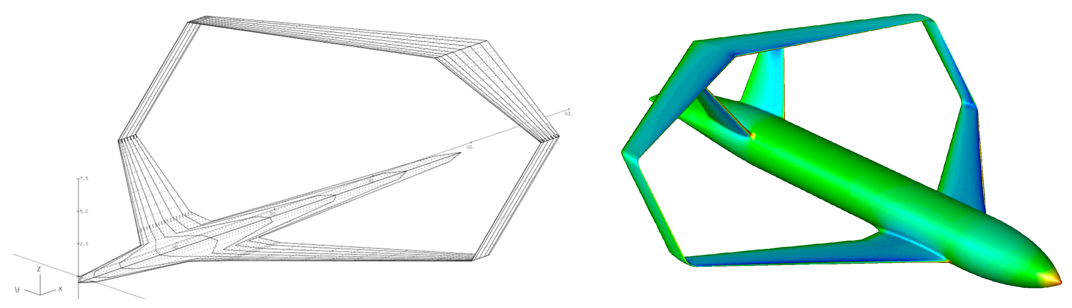
Figure 3.
Geometric design variables defining a box-wing lifting system.
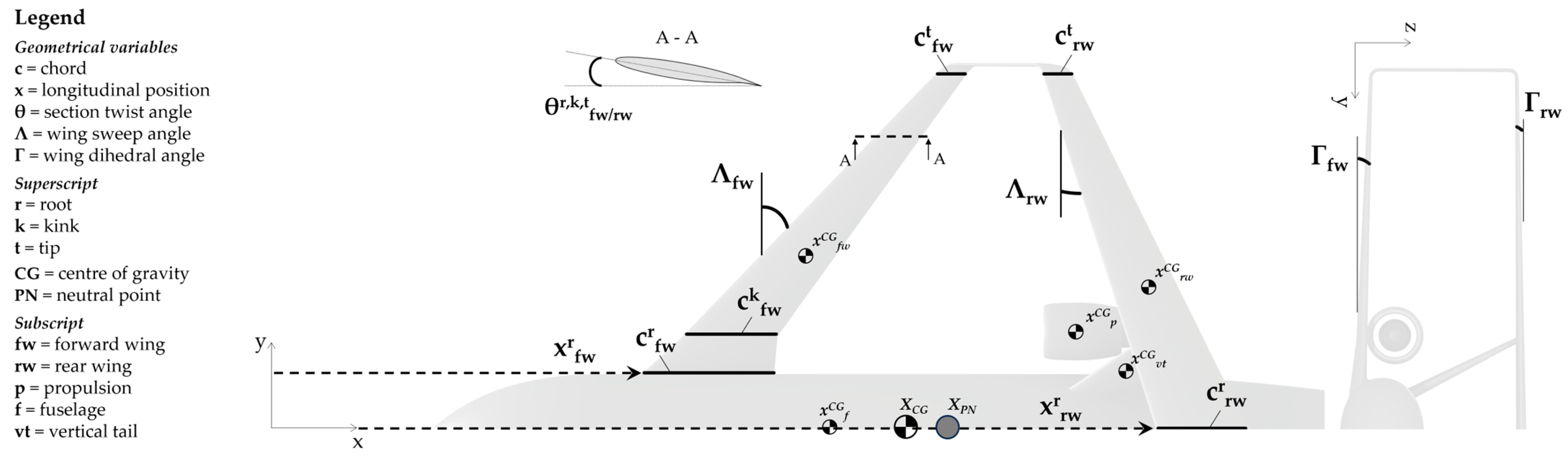
Figure 4.
Value of the ratio L/D for the optimal configurations of the three families; each marker type represents group of solutions with the same maximum wing loading constraint.
Figure 4.
Value of the ratio L/D for the optimal configurations of the three families; each marker type represents group of solutions with the same maximum wing loading constraint.

Figure 5.
Reference area S vs. CL for the optimal configurations of the three families; each marker type represents group of solutions with the same maximum wing loading constraint.
Figure 5.
Reference area S vs. CL for the optimal configurations of the three families; each marker type represents group of solutions with the same maximum wing loading constraint.
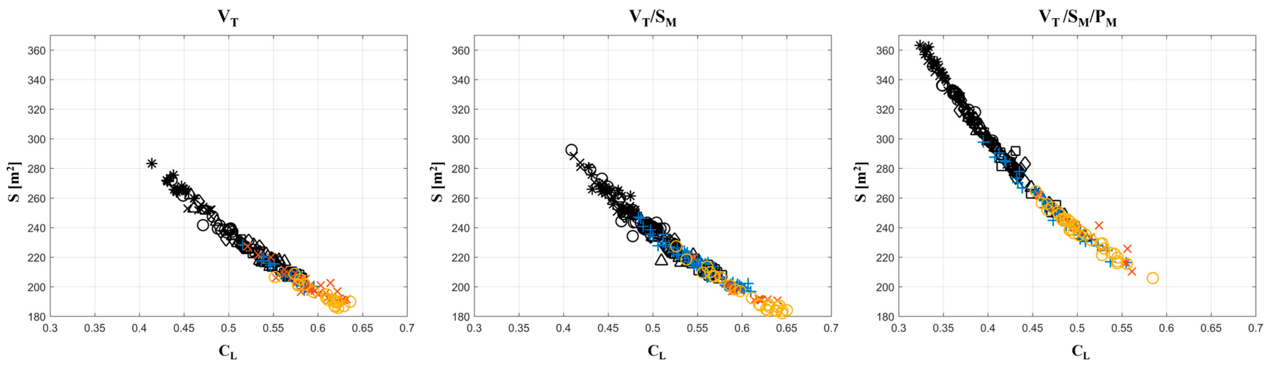
Figure 6.
Value of for the optimal configurations of the three families; each marker type represents group of solutions with the same maximum wing loading constraint.
Figure 6.
Value of for the optimal configurations of the three families; each marker type represents group of solutions with the same maximum wing loading constraint.
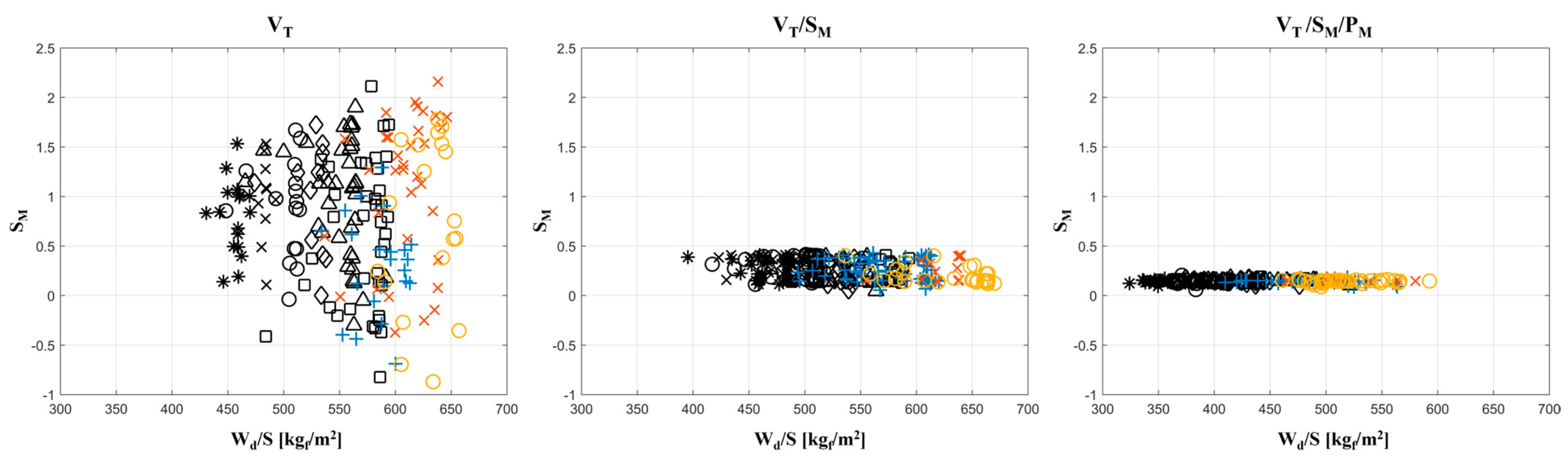
Figure 7.
Value of CM for the optimal configurations of the three families; each marker type represents group of solutions with the same maximum wing loading constraint.
Figure 7.
Value of CM for the optimal configurations of the three families; each marker type represents group of solutions with the same maximum wing loading constraint.
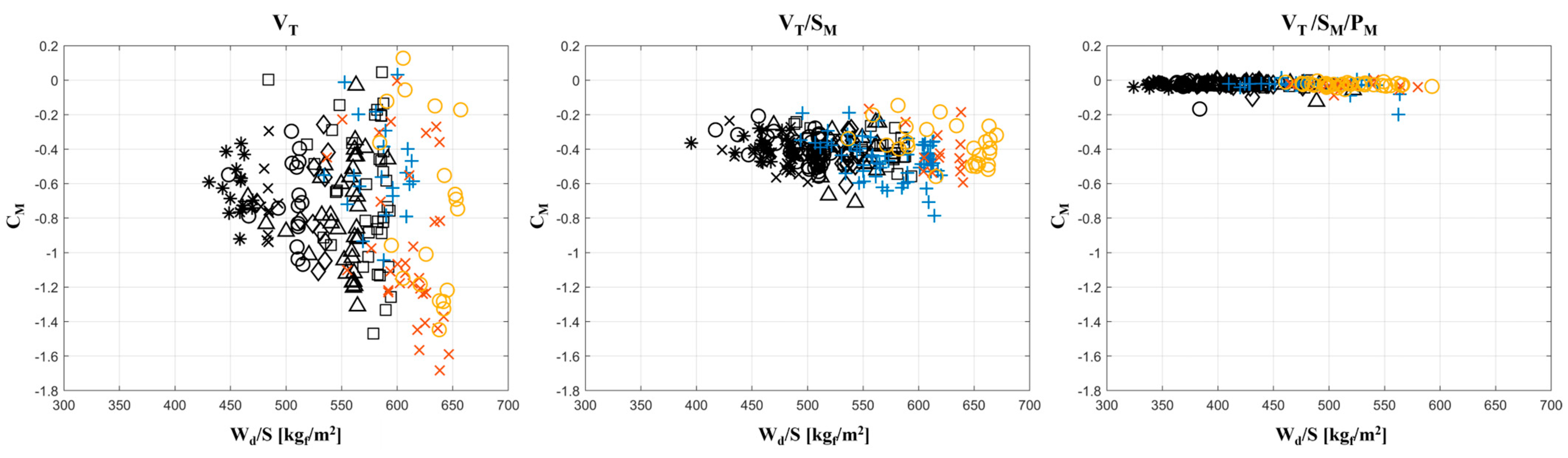
Figure 8.
Average values of the ratio L/D (left) and of S (right) varying Wd/S for the three families.
Figure 8.
Average values of the ratio L/D (left) and of S (right) varying Wd/S for the three families.

Figure 9.
Average values of individual wing loading for the three families.

Figure 10.
Conceptual sketch of the trim condition of a box-wing configuration.

Figure 11.
Conceptual sketch of a box-wing ‘anti-stall’ behaviour.

Figure 12.
Stable stall filter output; stable configurations are represented with a black marker.
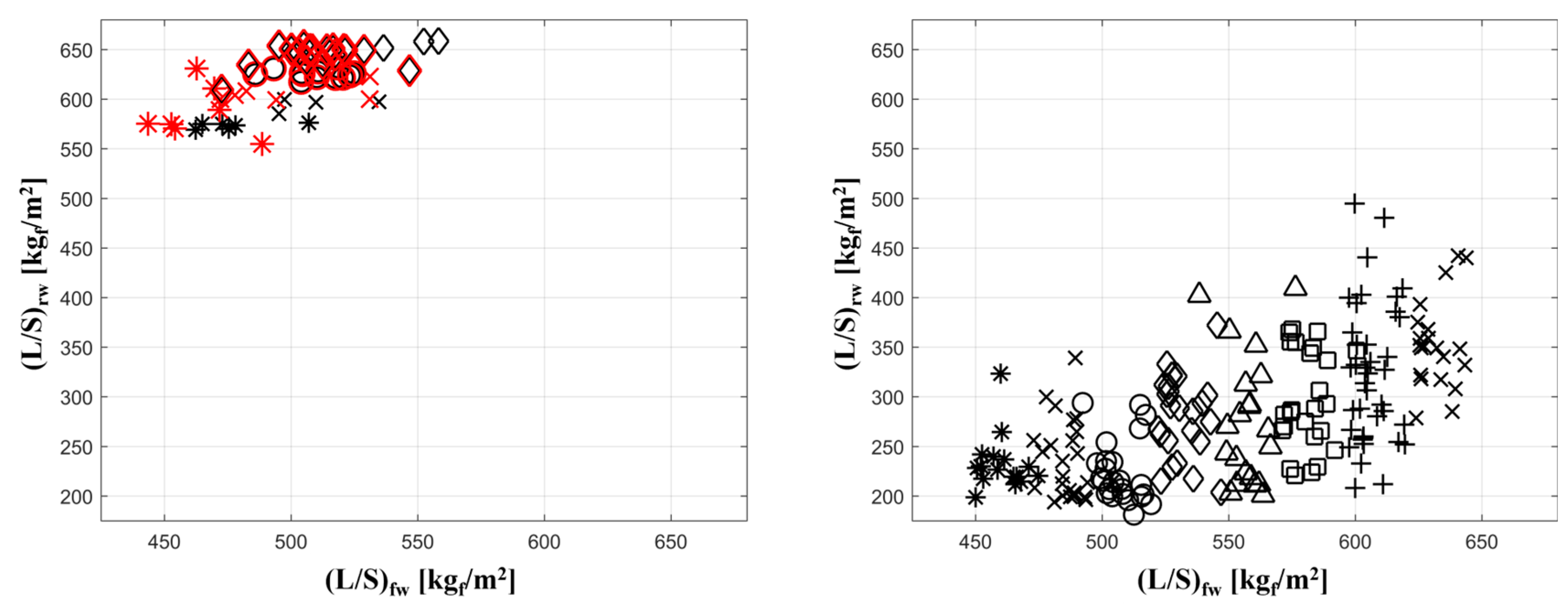
Figure 13.
Example of wings fuel tank arrangement (left), subdivision (centre) and related position (right).
Figure 13.
Example of wings fuel tank arrangement (left), subdivision (centre) and related position (right).

Figure 14.
Curves of CD-δe and CM-δe for the reference box-wing configuration.

Figure 15.
Variation in XCG, XCP, XNP, and δe trim for the case 60–40 front/rear fuel initial repartition.
Figure 15.
Variation in XCG, XCP, XNP, and δe trim for the case 60–40 front/rear fuel initial repartition.

Figure 16.
Movable layout for a reference box-wing configuration.
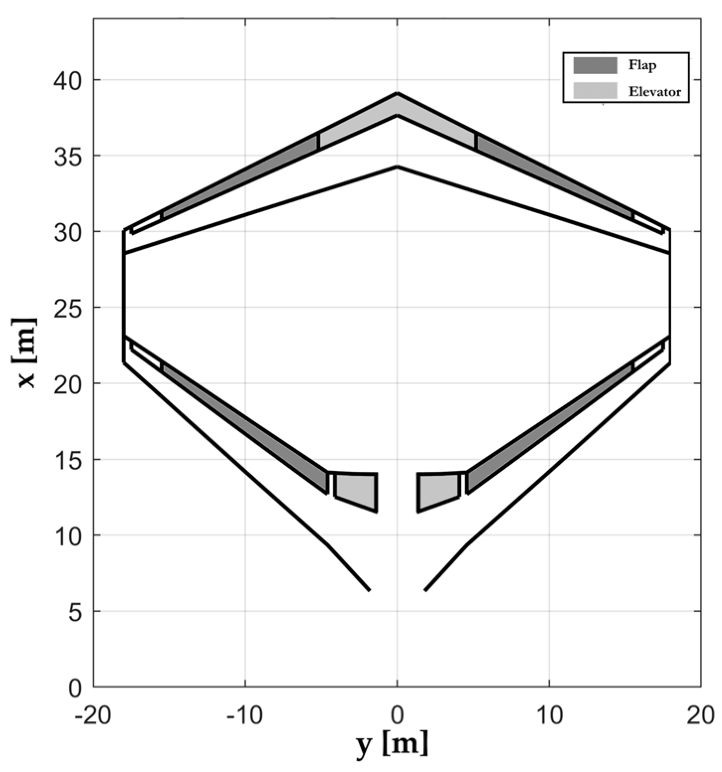
Figure 17.
Value of in the approach condition as a function of and .

Figure 18.
for front wing (left) and rear wing (right).

Figure 19.
Value of (approach) as a function of and .

Figure 20.
Rear wing flap technologies usually considered in box-wing aircraft design. Image adapted from [102].
Figure 20.
Rear wing flap technologies usually considered in box-wing aircraft design. Image adapted from [102].

Figure 21.
difference front/rear for the four rear flap technologies considered.

Figure 22.
Curve levels of the for the typical (four) rear flap technologies considered.

Figure 23.
Approach trim parameters: CL (left) and CM (right).

Figure 24.
Elevator deflection to reach the approach pitch trim.

Figure 25.
VTP typical design parameters.
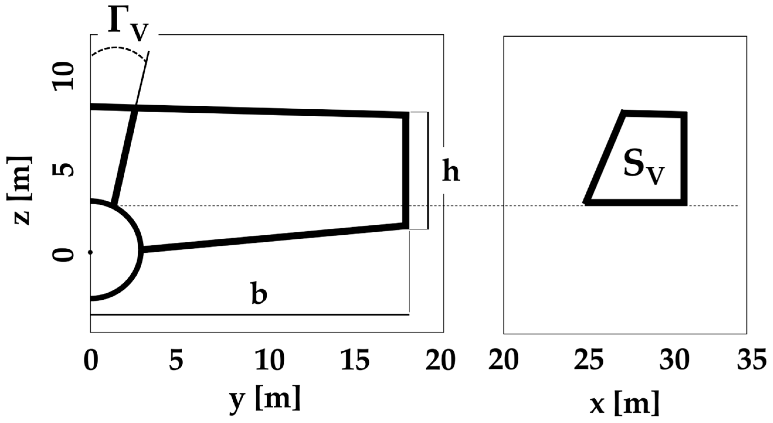
Figure 26.
Configurations selected to assess preliminary directional performance.

Figure 27.
Contour map of varying h/b and ΓV.
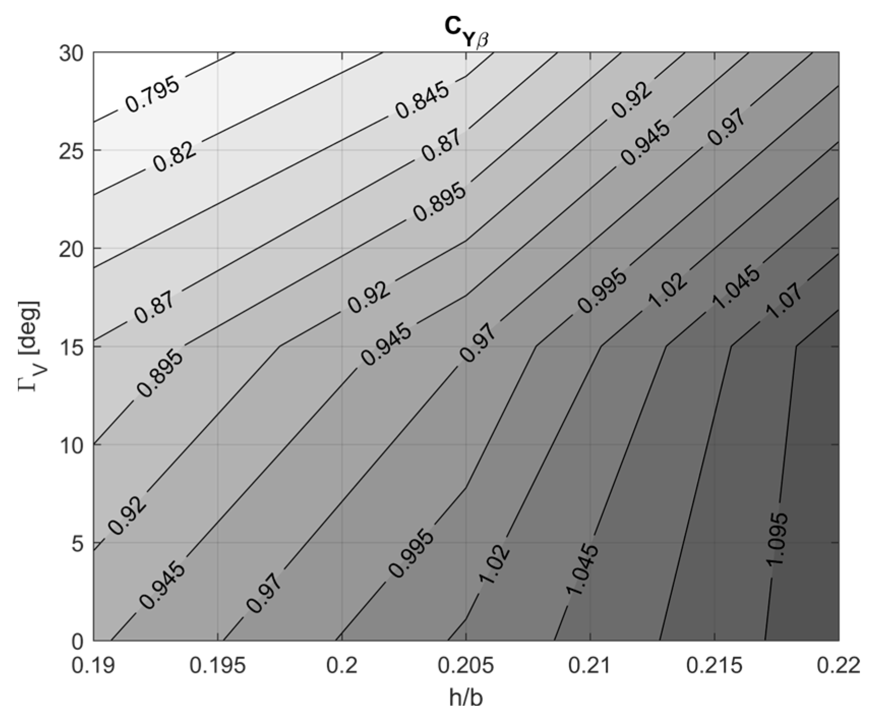
Figure 28.
Contour map of CNβ varying XCG and ΓV, for three values of h/b.

Figure 29.
VTP installation varying inclination angle ΓV.
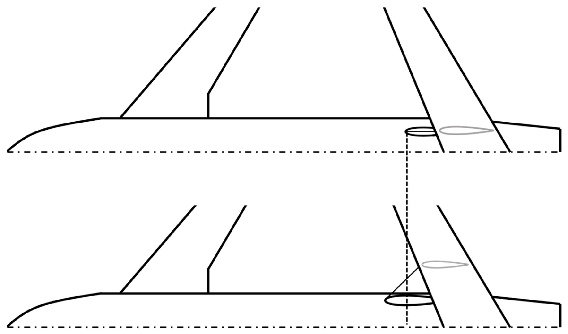
Figure 30.
Example of pressure distribution on a box-wing vertical tip-wing.

Figure 31.
Longitudinal static margin of stability contour map varying h/b and ΓV.
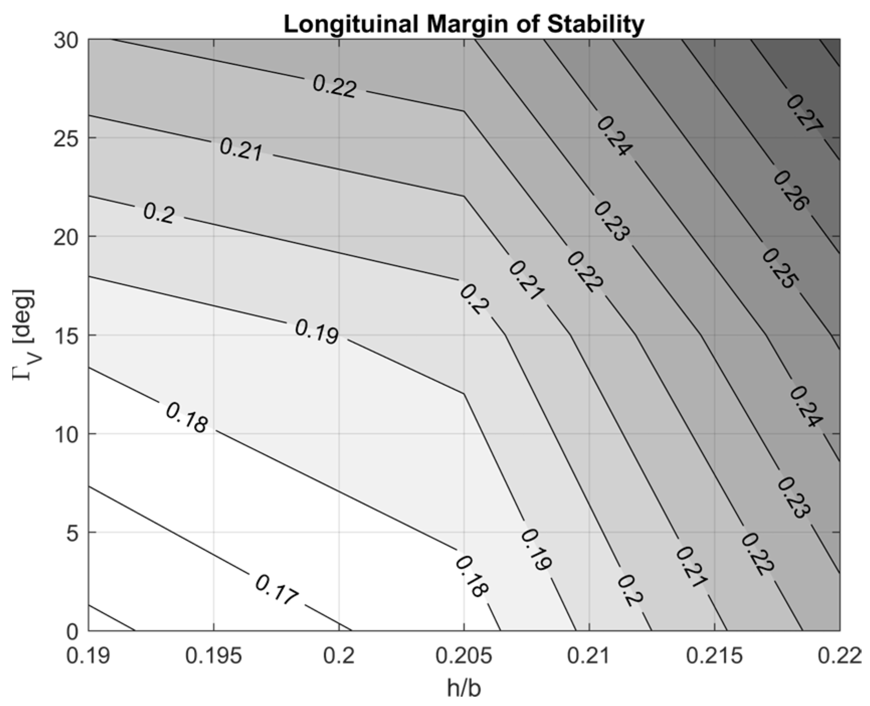

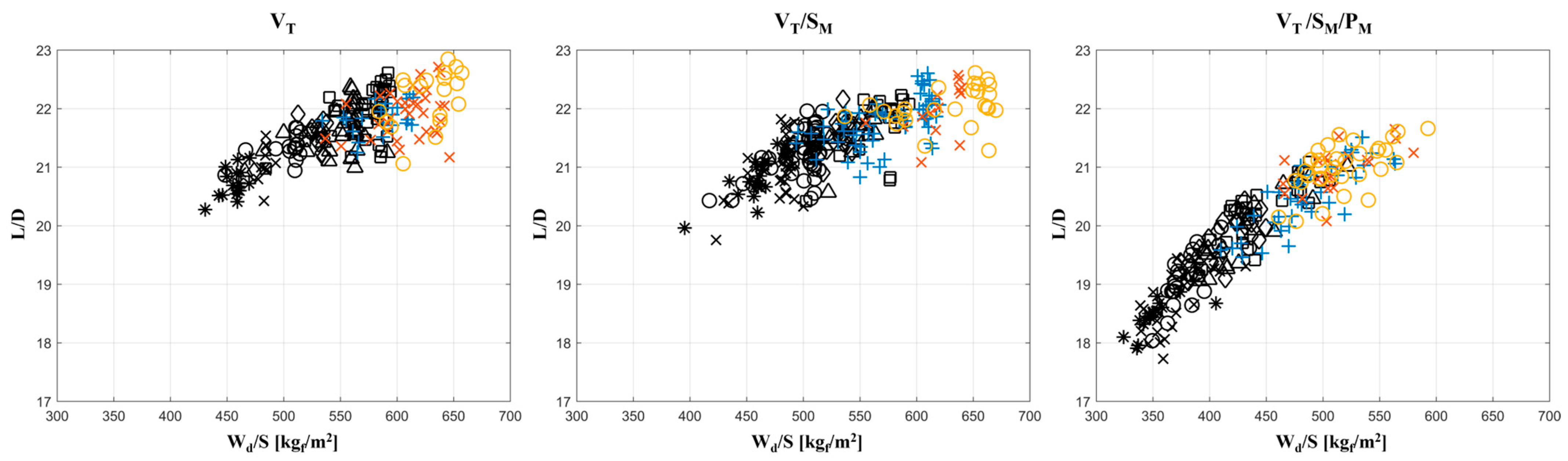
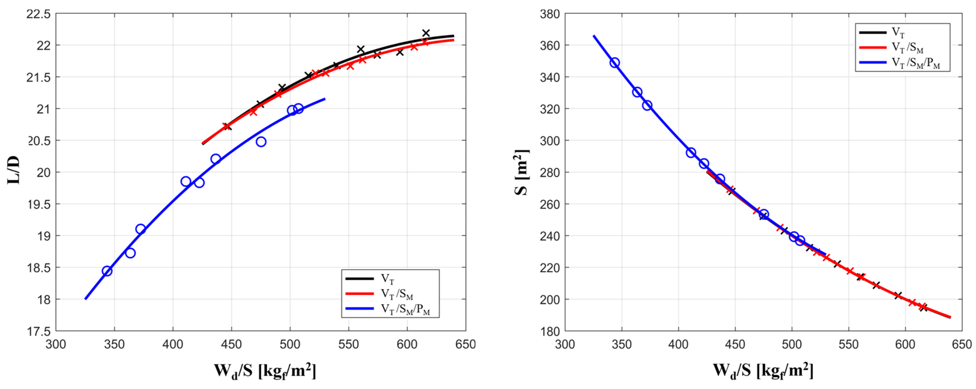
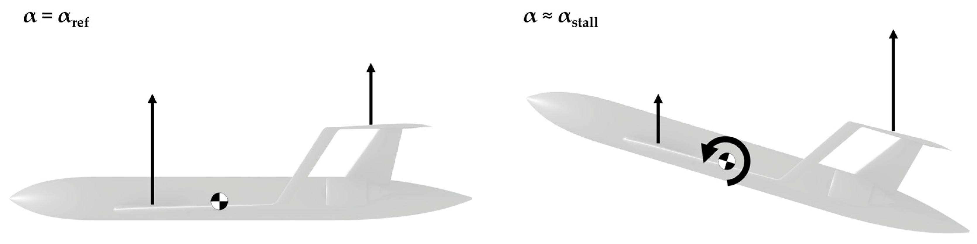
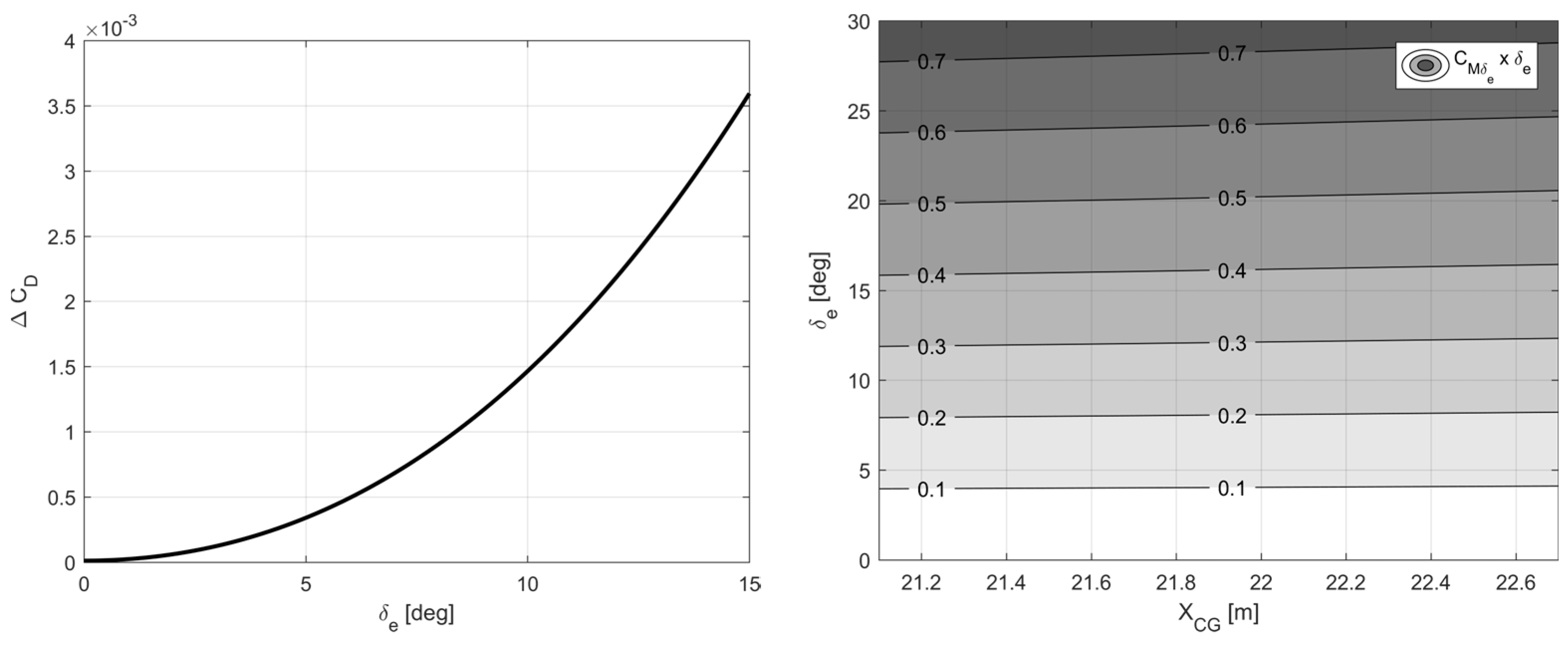
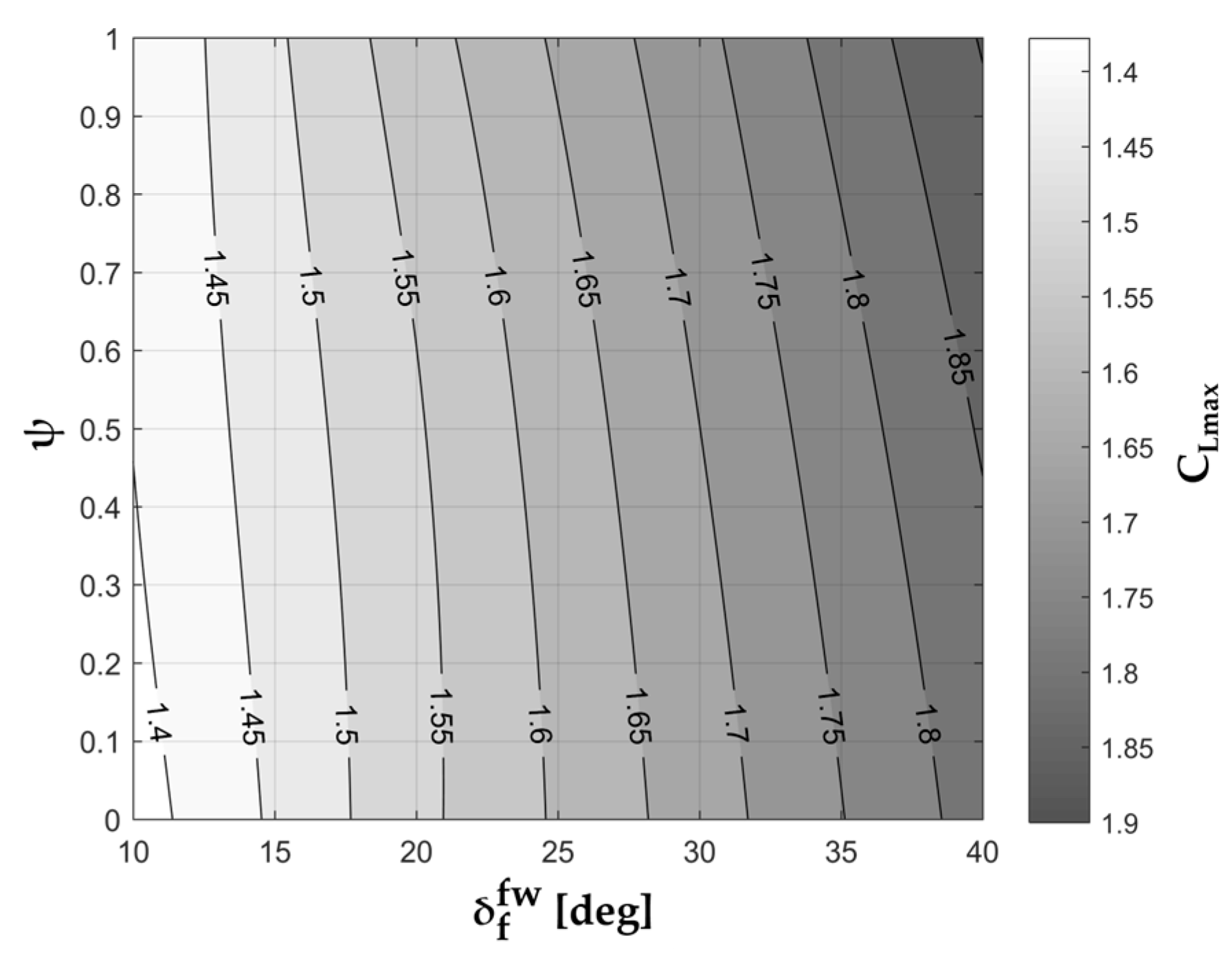
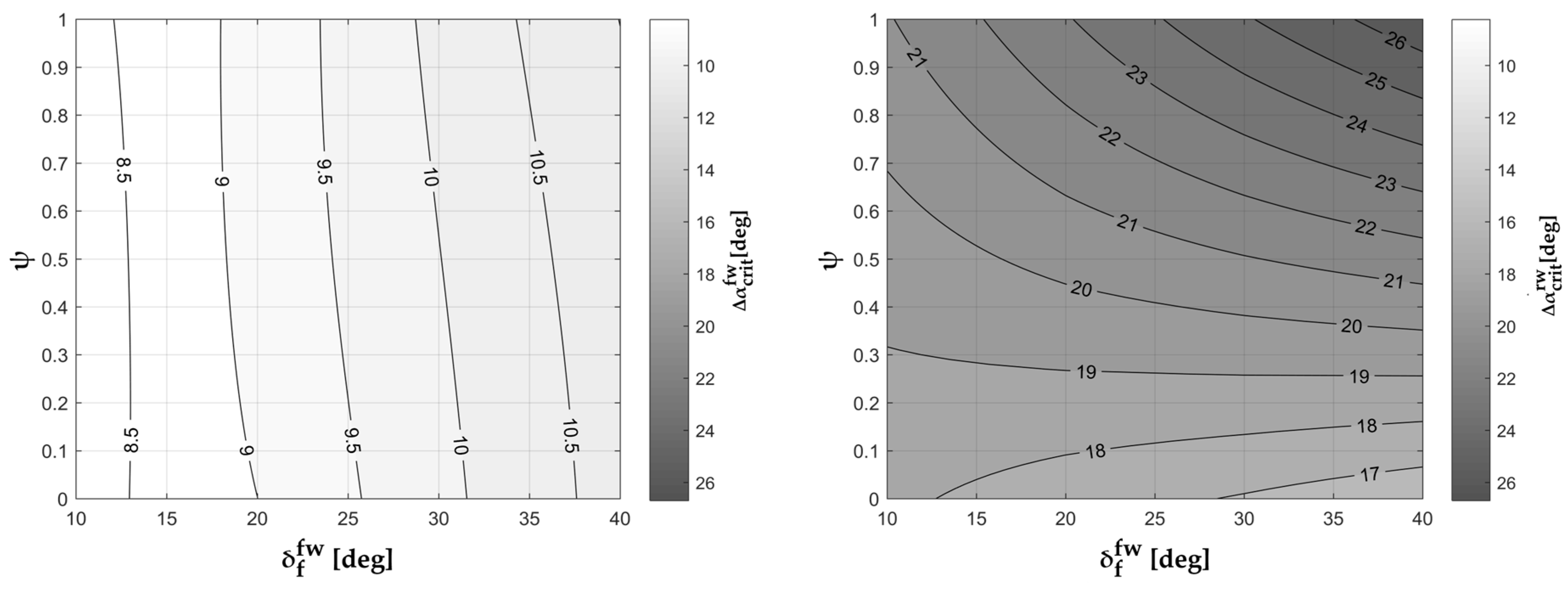
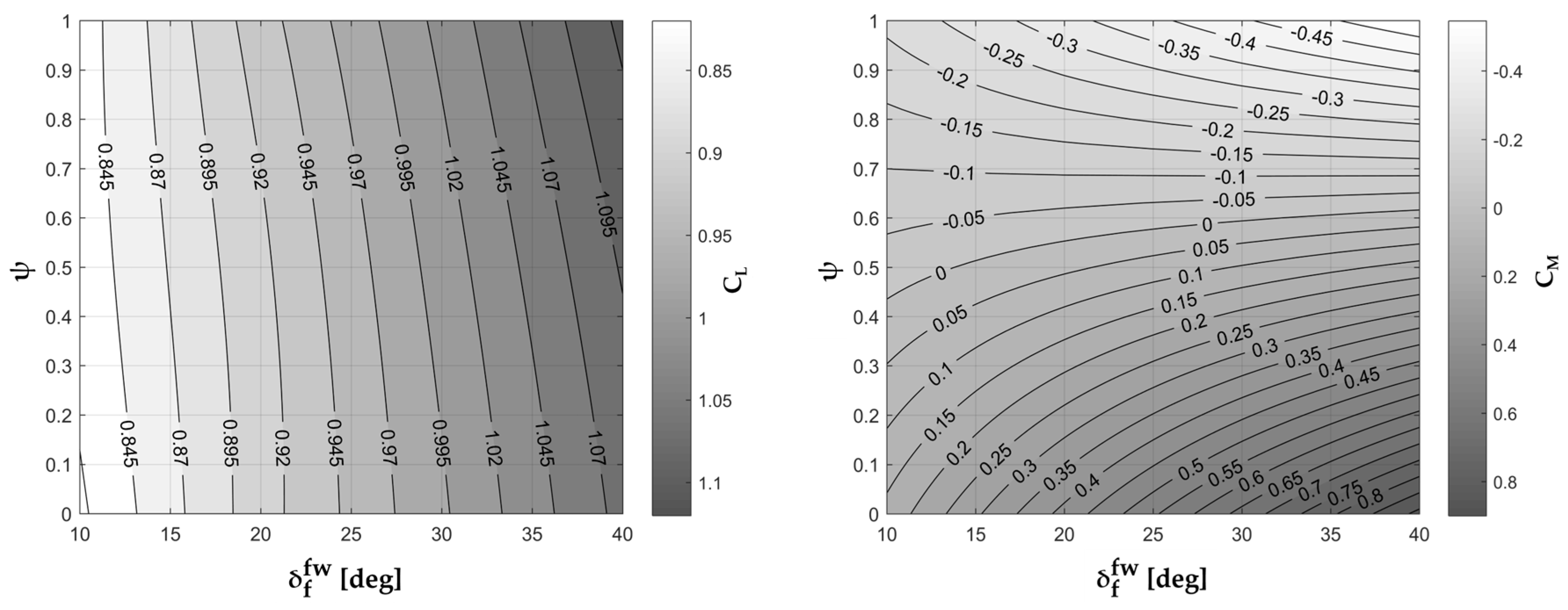
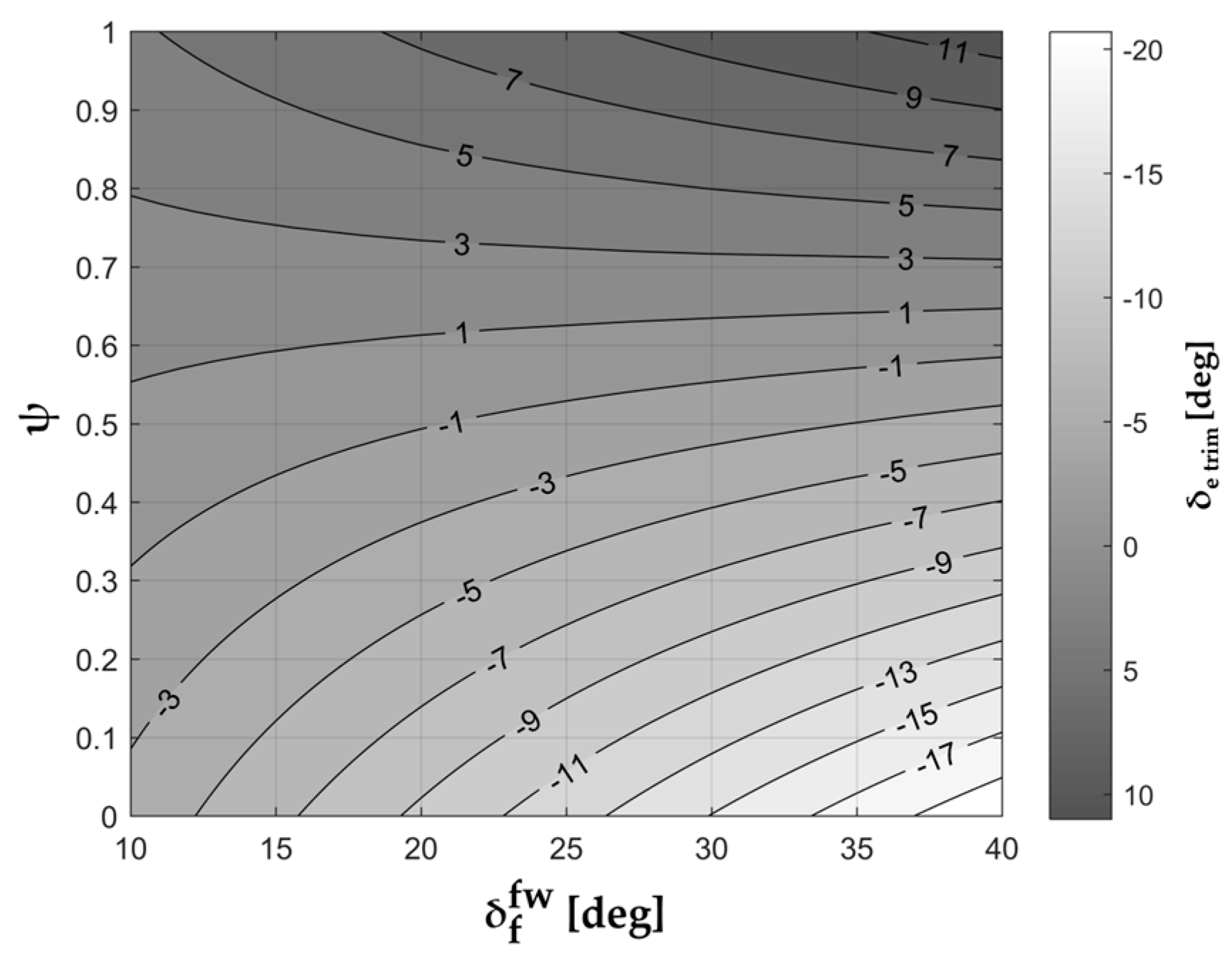
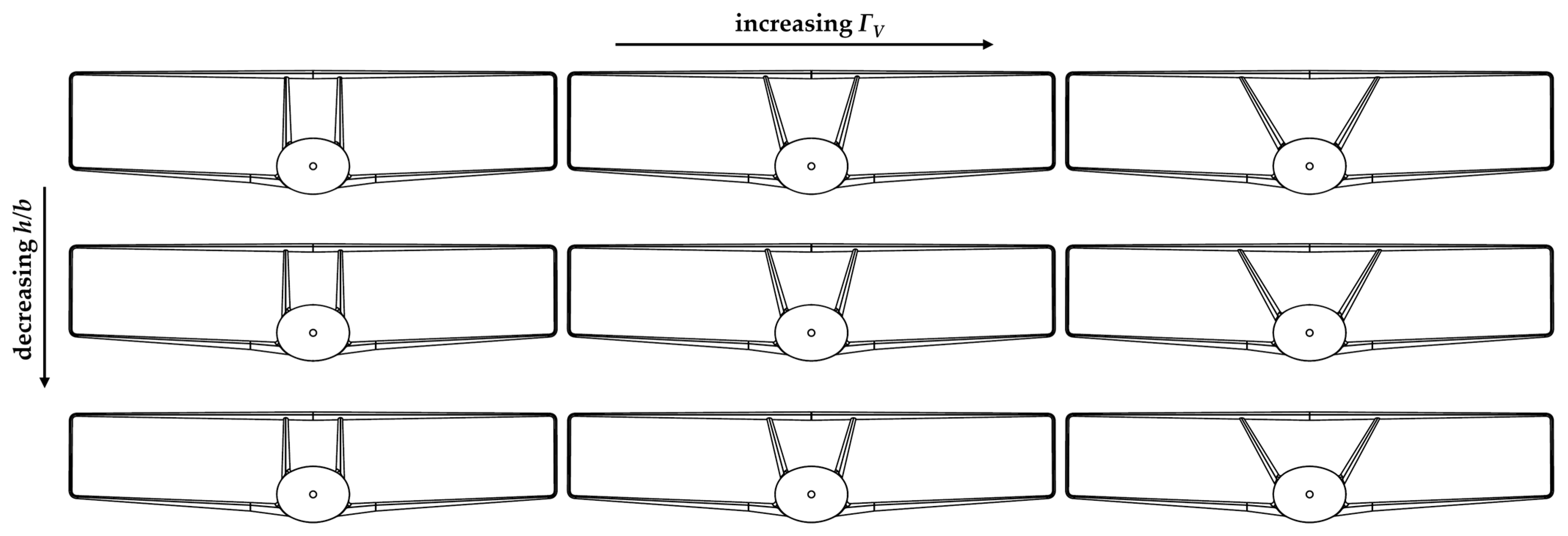
Table 1.
Classification of common models for aircraft aeromechanic assessment.
| Level | Type | Implementation | Time/Cost | Application |
|---|---|---|---|---|
| 0 | textbook | Roskam [62,63] | very low | initial sizing |
| 0 | database | DATCOM [64,65] | very low | initial sizing |
| 1 | potential | VLM [66,67] | low | conceptual |
| 1.5 | potential | 3D Panel Method [68,69] | medium | conceptual |
| 2 | CFD | RANS [70,71] | high | preliminary |
| 2.5 | CFD | LES/DES [72,73] | very high | advanced |
| 3 | experimental | wind tunnel [74,75] | extremely high | project specific |
| 4 | experimental | flight test [76,77] | extremely high | project specific |
Table 2.
VLM and RANS main technical specifications.
| Type of Simulation | Code | Geometry | Input Required | Hardware (Minimum) | Average Simulation Time |
|---|---|---|---|---|---|
| VLM | AVL | 2D panels | Plain text file | Any current laptop | 1–5 s |
| RANS | ANSYS | 3D assembly | CAD model + surface-volume meshing | Parallel computing, eight cores, 32 GB RAM | 18–24 h |
Table 3.
Constraints for the different families of configurations: VT = vertical trim, SM = stability margin, and PT = pitch trim.
Table 3.
Constraints for the different families of configurations: VT = vertical trim, SM = stability margin, and PT = pitch trim.
| Name | Constraints | Notes |
|---|---|---|
| VT | Only vertical trim | |
| VT/SM | Vertical trim and longitudinal static stability | |
| VT/SM/PT | Vertical trim, longitudinal static stability, and pitch trim |
Table 4.
Main features of box-wing configurations available in the literature.
| Name [Refs.] | Class | MTOW [kgf] | Sfw [m2] | Srw [m2] | Λfw [deg] | Λrw [deg] | (L/S)fw [kgf/m2] | (L/S)rw [kgf/m2] | R |
|---|---|---|---|---|---|---|---|---|---|
| MSx [8] | SMR | 125,100 | 118 | 109 | 42 | −20 | 639 | 487 | 0.76 |
| MS1.2 [79] | SMR | 126,400 | 135 | 131 | 37 | −24 | 574 | 338 | 0.58 |
| PrP-186 [79] | SMR | 78,100 | 73 | 69 | 34 | −20 | 625 | 365 | 0.58 |
| Prosib HE [93] | REG | 22,900 | 40 | 38 | 24 | −15 | 385 | 195 | 0.51 |
| Prosib HE [94] | REG | 50,200 | 88 | 84 | 2 | −5 | 350 | 185 | 0.53 |
| TiltOne [95] | UAM | 2512 | 12 | 12 | 0 | 0 | 116 | 78 | 0.67 |
| BW P180 [96] | GA | 6240 | 12 | 13 | 11 | −10 | 322 | 149 | 0.46 |
| PrP250 [97] | LR | 230,000 | 192 | 160 | 37 | −24 | 770 | 414 | 0.54 |
| Freighter [98] | F | 625,000 | 571 | 500 | 40 | −29 | 626 | 400 | 0.63 |
Disclaimer/Publisher’s Note: The statements, opinions and data contained in all publications are solely those of the individual author(s) and contributor(s) and not of MDPI and/or the editor(s). MDPI and/or the editor(s) disclaim responsibility for any injury to people or property resulting from any ideas, methods, instructions or products referred to in the content. |
© 2023 by the authors. Licensee MDPI, Basel, Switzerland. This article is an open access article distributed under the terms and conditions of the Creative Commons Attribution (CC BY) license (https://creativecommons.org/licenses/by/4.0/).
Share and Cite
MDPI and ACS Style
Abu Salem, K.; Palaia, G.; Quarta, A.A.; Chiarelli, M.R. Preliminary Analysis of the Stability and Controllability of a Box-Wing Aircraft Configuration. Aerospace 2023, 10, 874. https://doi.org/10.3390/aerospace10100874
AMA Style
Abu Salem K, Palaia G, Quarta AA, Chiarelli MR. Preliminary Analysis of the Stability and Controllability of a Box-Wing Aircraft Configuration. Aerospace. 2023; 10(10):874. https://doi.org/10.3390/aerospace10100874
Chicago/Turabian StyleAbu Salem, Karim, Giuseppe Palaia, Alessandro A. Quarta, and Mario R. Chiarelli. 2023. "Preliminary Analysis of the Stability and Controllability of a Box-Wing Aircraft Configuration" Aerospace 10, no. 10: 874. https://doi.org/10.3390/aerospace10100874
Note that from the first issue of 2016, this journal uses article numbers instead of page numbers. See further details here.