
Free Vibrations of a New Three-Phase Composite Cylindrical Shell

1
Beijing Key Laboratory of Nonlinear Vibrations and Strength of Mechanical Structures, Faculty of Materials and Manufacturing, Beijing University of Technology, Beijing 100124, China
2
Department of Mathematics, Beijing Institute of Graphic Communication, Beijing 102600, China
*
Author to whom correspondence should be addressed.
Aerospace 2023, 10(12), 1007; https://doi.org/10.3390/aerospace10121007
Submission received: 10 October 2023
/
Revised: 21 November 2023
/
Accepted: 27 November 2023
/
Published: 29 November 2023
(This article belongs to the Special Issue Design and Analysis of Advanced Composites and Structures in Aerospace)
Abstract
:The novel concept of a functionally graded three-phase composite structure is derived from the urgent need to improve the mechanical properties of traditional two-phase composite structures in aviation. In this paper, we study the free vibrations of a new functionally graded three-phase composite cylindrical shell reinforced synergistically with graphene platelets and carbon fibers. We calculate the equivalent elastic properties of the new three-phase composite cylindrical shell using the Halpin-Tsai and Mori-Tanaka models. The governing equations of this three-phase composite cylindrical shell are derived by using first-order shear deformation theory and Hamilton’s principle. We obtain the natural frequencies and mode shapes of the new functionally graded three-phase composite cylindrical shell under artificial boundary conditions. By comparing the results of this paper with the numerical results of finite element software, the calculation method is verified. The effects of the boundary spring stiffness, GPL mass fraction, GPL functionally graded distributions, carbon fiber content, and the carbon fiber layup angle on the free vibrations of the functionally graded three-phase composite cylindrical shell are analyzed in depth. The conclusions provide a certain guiding significance for the future application of this new three-phase composite structure in the aerospace and engineering fields.
1. Introduction
In aviation, commercial aircraft attach great importance to the cost reduction caused by weight reduction and energy conservation. The application of composite materials in commercial aircraft has become a growing trend based on these urgent requirements, which are emerging and ascendant. The proportion of advanced composite materials in the airframe components of aircraft has become a significant indicator to measure the progressiveness of its structure. However, as one of the important components of large aircraft structures, the electric conductivity of carbon fiber-reinforced composite structures is poor. This weakness makes the aircraft unable to divert the current and may lead to severe structural damage after a lightning strike. In order to achieve lightning protection and ensure the operational safety of the aircraft, aviation engineers usually choose to attach copper mesh to the surface of the aircraft structures. Nevertheless, this measure runs counter to the original intention of weight reduction, as it adds to the airframe weight of the aircraft [1]. Is there a solution that can achieve the best of both worlds?
Novel materials will give birth to a new generation of equipment, and scientists are pinning their hopes of solving the above problem on these new materials with distinctive functions. In recent years, materials scientists have tried to add graphene platelets (GPLs) to traditional carbon fiber-reinforced composite materials. When the content of GPLs exceeds the percolation threshold, conductive paths appear, and the conductivity of the composite material is greatly improved. Thus, a new type of three-phase composite structure with electric conductivity is obtained [2,3]. If we apply this structure to aircraft manufacturing, it is possible to obtain the next generation of aircraft lightning protection solutions, which have broad application prospects [4,5,6,7,8]. It is noteworthy that the new three-phase composite structure with electrical conductivity can also have functionally graded (FG) characteristics by adjusting the GPLs distribution form, just like the new FG three-phase composite shell reinforced synergistically with GPLs and carbon fibers (studied in this paper), as shown in Figure 1. The new FG three-phase composite structure reinforced synergistically by GPLs and carbon fibers integrates the advantages of carbon fiber reinforced-composite structures and FG-reinforced composite structures, which is regarded as a multi-scale composite structure with significant practical value regarding engineering in aviation, aerospace, navigation, and other fields [9,10]. Although a large number of scholars have carried out in-depth research on the vibration characteristics of two-phase composite structures, such as carbon fiber-reinforced composite structures [11,12] and FG-reinforced composite structures [13,14,15], there are few studies on the vibrations of the new FG three-phase composite structure reinforced synergistically by GPLs and carbon fibers. Therefore, the free vibrations of the new FG three-phase composite cylindrical shell structure are studied deeply in this paper to make this kind of new structure reinforced synergistically with GPLs and carbon fibers be applicable to related fields earlier and more widely.
Composite laminated cylindrical shell structures have been widely used in the fields of aerospace, automotive, and defense [16,17,18]. Their vibration-based problems have been appreciated, and many related pieces of research have been reported over several decades [19,20]. The artificial boundary spring method is often applied in the free vibration analysis of shell structures. Based on the artificial boundary spring method, Li et al. [21] studied the free vibrations of composite laminated thin-walled cylindrical shells, and Guo et al. [22] analyzed the vibration characteristics of three laminated shell structures. Moreover, different approximation calculation methods are used, such as the reverberation ray matrix method, the wave base method, etc., during the numerical analysis of the free vibration characteristics of composite laminated shells. By using the reverberation ray matrix method, Tang et al. [23] and Wang et al. [24] studied the free vibrations of cylindrical shells based on Flügge thin-shell theory and first-order shear deformation theory (FSDT), respectively. He et al. [25], Shi et al. [26], and He et al. [27] analyzed the problems of the free vibrations of shell structures under arbitrary conditions.
In recent years, scholars have discovered that new advanced nanomaterials have superb electrical, mechanical, and thermal properties, such as carbon nanotubes (CNTs), graphene platelets (GPLs), and other graphene derivatives. These new nanomaterials are incorporated into the polymer matrix in the form of reinforcements to improve the comprehensive performance of conventional composite materials [28]. Then, the nanofiller-reinforced FG composite materials are obtained by introducing the concept of functionally graded materials (FGMs), in which the nanofiller reinforcements show a gradient distribution pattern along the direction of thickness of the polymer matrix, and their material properties also show a continuous and relatively smooth variation along the direction of thickness [29]. The research on vibration characteristics of the nanofiller reinforced FG composite shell and panel structures has aroused wide attention.
Thang et al. [30] performed a free vibration analysis of a thin-walled FG composite cylindrical shell, considering neutral surface effects. By using FSDT, Wang et al. [31] and Qin et al. [32] investigated the free vibrations of CNT-reinforced FG composite rotating spherical shells and cylindrical shells, respectively. Sobhani et al. [33] analyzed the free vibration of nanofiller-reinforced FGM cone-cylinder-cone shells by using the generalized differential product method. Abedini et al. [34] analyzed the free vibration of GPL-reinforced FGM cylindrical shells. Liu et al. [29] used the three-dimensional elasticity theory to analyze the free vibration characteristics and buckling of GPL-reinforced FG composite cylindrical shells. Based on Sanders’ shell theory, Ghamkhar et al. [35] investigated the free vibration of FGM cylindrical shells under circular support conditions. Chai et al. [14] analyzed the vibration of composite-joined conical-cylindrical shells by using the Donnell shell theory. On top of that, Xie et al. [36] investigated the free vibrations of CNT-reinforced FGM cylindrical panels under general elastic support conditions. By using FSDT, Van Do et al. [37] analyzed the free vibrations and bending properties of the GPL-reinforced FGM cylindrical panels. Khoa et al. [38] studied the nonlinear dynamic responses of single-walled CNT-reinforced FGM cylindrical panels using the fourth-order Runge-Kutta algorithm. Twinkle et al. [39] investigated the vibration of GPL-reinforced FGM cylindrical panels.
The nanofiller-reinforced FGMs described in the previous paragraphs can be seen as a hybrid matrix (HM); it is obtained by filling the nanoscale reinforcements into a polymer matrix [40]. Continuing to add the macroscopic reinforcements in HM materials can make a three-phase composite material, where the carbon or glass fibers are usually chosen as the macroscopic-level reinforcements. The FG three-phase composite structures combine the features of the two-phase composite laminated structures and the two-phase FG composite structures, and they also concentrate on the advantages of both of them. Therefore, the FG three-phase composite shell structures have better comprehensive performance and richer mechanical properties with wider applicability, which can further improve the vibration characteristics of the shell.
Two-phase composite shell structures have been studied further by previous researchers, and the vibration characteristics of three-phase composite shell structures have been less studied in comparison. Nevertheless, there are still some published studies that can provide the references for our research in this paper. Ebrahimi et al. [41] used the Halpin-Tsai model to calculate the effective material properties and analyzed the vibration characteristics of the three-phase composite plates. Gholami et al. [42] investigated the nonlinear buckling of the three-phase composite plate. Arani et al. [43] studied the vibration characteristics of a beam under the action of an external magnetic field. Karimiasl et al. [44] analyzed the vibrations of the three-phase composite doubly curved shell composed of polymer/CNTs/fibers and polymer/GPLs/fibers, respectively. Rezaiee-Pajand et al. [40] used two homogenization methods, Han and Chamis, to calculate the equivalent properties of three-phase composite materials composed of polymer/CNTs/carbon fiber, then studied the free vibrations of the conical shell. Yousefi et al. [45] calculated the effective elastic properties of three-phase composites reinforced with carbon nanotubes and carbon fibers based on the Mori-Tanaka-Eshelby method and the Han homogenization method. Then, the free vibration characteristics of truncated conical shells were investigated. Sobhani et al. [46] studied the vibrations of the hemispherical cylindrical shells of the three-phase composites of polystyrene, CNTs, and carbon fibers.
By reviewing and summarizing the relevant literature, we find that there are relatively more studies on the vibration characteristics of three-phase composite beam and plate structures using the nanofillers of CNTs. In contrast, the vibrations of three-phase composite cylindrical shell structures are less reported when the nanofillers are GPLs. When compared with CNTs, GPLs have at least two advantages as the nanofillers. On the one hand, GPLs are considered to be excellent nanoscale reinforcing fillers because of their larger specific surface area, high spreading ratio, and high strength. On the other hand, the cost of GPLs is much lower than that of producing CNTs when using bulk graphite for the large-scale production of graphene, which is superior to CNTs [47]. In addition, we should note that the composite cylindrical shell structure is one of the most common and critical structures, which is widely used in aerospace, civil engineering, transportation, and other fields, and the studies of its vibration characteristics are particularly important. From these perspectives, we should pay more attention to the vibration problems of the FG three-phase composite shell structures with nanofillers using GPLs.
The free vibrations of a new FG three-phase composite cylindrical shell reinforced synergistically with GPLs and carbon fibers are studied in this paper, where epoxy resin is the matrix, and GPLs and carbon fibers are the two types of reinforcements, respectively. Firstly, we used the Halpin-Tsai model and the Mori-Tanaka model to obtain the equivalent mechanical properties of the FG three-phase composite material. Then, the governing equations for the free vibrations of the FG three-phase composite cylindrical shell are derived based on FSDT and Hamilton’s principle. Herein, artificial boundary conditions were introduced, and the equations were discretized using the Galerkin method. The discrete equations were solved to obtain the natural frequencies. Finally, we investigate the effects of boundary spring stiffness, GPL mass fraction, GPL FG distributions, carbon fiber content, and the carbon fiber layup angle on the free vibrations of cylindrical shells. The research in this paper is helpful in elucidating the free vibration characteristics of the three-phase composite cylindrical shell and has important theoretical and engineering significance for the further application of the three-phase composite structure.
2. Mechanical Properties of the Three-Phase Composite Material
Just as its name implies, the FG three-phase composite material is made by combining three substances. In this section, GPL-reinforced epoxy resin is used as the hybrid matrix (HM), and the equivalent mechanical properties of the HM are first calculated mainly by using the Halpin-Tsai model. Then, the Mori-Tanaka model is mainly applied to calculate the equivalent mechanical properties of the macroscopic fiber-reinforced HM.
2.1. Halpin-Tsai Model for the Hybrid Matrix
The HM consists of a mixture of a polymer matrix and nano-reinforcements. In this paper, we chose the epoxy matrix, and we used GPLs as the nano-reinforcements. The GPLs were distributed in the epoxy matrix with different FG distributions. In our research, we consider five forms of GPL FG distributions in the direction of cylindrical shell thickness. Five different GPL FG distributions are shown in Figure 1, where the deeper color indicates the higher GPL content. The volume fractions of the GPLs in each layer at different functional gradients are as follows [38,48]:
where indicates the volume fraction of GPLs uniformly distributed in the epoxy matrix. is the total thickness, and denotes the co-ordinate value along the direction of the thickness.
In Equation (1), can be expressed as follows:
where and denote the mass fraction and the density of GPLs, respectively, and the density of the epoxy matrix is indicated as .
The Halpin-Tsai model is used to calculate the equivalent elastic modulus of the HM; the specific equation is shown as follows:
where indicates the elastic modulus of the matrix.
In Equation (3), , and , there are two auxiliary parameters, which can be expressed by the following equations:
The elastic modulus of the GPLs is denoted as and the parameters , and is determined by the geometric parameters of the reinforcement as follows:
where the length, width, and thickness of the GPLs are denoted by ,, and , respectively.
According to the mixing rules, the Poisson’s ratio and density of the HM at each layer can be calculated. The calculation formula is shown as follows:
where and denote the Poisson’s ratio and density of the layer at the co-ordinate value along the direction of the thickness, respectively; and are the volume fraction of the epoxy matrix and the volume fraction of the GPL reinforcement at the co-ordinate value of along the direction of the thickness, respectively. From the mixing rule, the sum of and is 1. and denote the Poisson’s ratio and density of GPL reinforcement, respectively, and the detailed parameter values are shown in Table 1. and indicate the Poisson’s ratio and density of epoxy matrix, respectively, and the detailed parameter values are shown in Table 2.
2.2. Mori-Tanaka Method for Three-Phase Composites
The FG three-phase composite material reinforced synergistically with GPLs and carbon fibers was obtained by adding the carbon fiber reinforcement to the FG HM. In this case, each layer of the HM is an isotropic material, and the equivalent mechanical properties have been calculated based on the Halpin-Tsai model in the previous subsection. The carbon fiber reinforcements are transversely isotropic materials, with the longitudinal and transverse elastic modulus defined as and . and represent the shear modulus, is Poisson’s ratio. The transversely isotropic materials have the properties of and . The mechanical properties of the carbon fibers are given in Table 3.
The equivalent mechanical properties of the FG three-phase composite material were obtained by using the Mori-Tanaka method [49] as follows:
In Equations (7a)–(7g), and denote the equivalent longitudinal modulus of elasticity and the equivalent transverse modulus of elasticity, respectively. and represent the equivalent in-plane shear modulus and the equivalent out-of-plane shear modulus, respectively. denotes the longitudinal Poisson’s ratio. and are two auxiliary parameters, the expressions of which are shown as follows:
Based on the mixing rule, we obtain the equivalent density of the FG three-phase composite material as follows:
3. Governing Equations of Motion
Cylindrical shell structures have a wide range of applications in the aerospace, marine, and transportation fields. The mechanical properties of cylindrical shell structures can be greatly improved by using new materials. Therefore, the research object of this paper is the FG three-phase composite cylindrical shell reinforced synergistically with GPLs and carbon fibers, as shown in Figure 1. In our research, the axial length of the three-phase composite cylindrical shell is , the radius of the midplane is , and the thickness is . In the following study, the geometrical parameters of the cylindrical shell are kept constant without any special specification. A column co-ordinate system is established at the midplane of the cylindrical shell, as shown in Figure 2, where , , and are the axial co-ordinate direction, the circumferential co-ordinate direction, and the radial co-ordinate direction of the cylindrical shell, respectively. The deformation of the cylindrical shell along the axial, circumferential, and radial directions is represented as , , and , respectively. It should be noted, in particular, that during the modeling of the dynamics of cylindrical shells, we mainly refer to Reddy’s book: Mechanics of Laminated Composite Plates and Shells Theory and Analysis [16].
3.1. Governing Equations for Cylindrical Shells
The displacement fields of a cylindrical shell are given based on FSDT [16]. These equations are shown as follows:
where , , and denote the displacements along the x-axis,-axis, and z-axis of a point on the middle plane: z = 0. In addition, and indicate the angles of rotation around the -axis and x-axis, respectively.
Then, we obtain the strain components according to the von-Karman geometric nonlinear relationship as follows:
where
In Equations (11) and (12), , , , , and denote the strain components. The constitutive relations of the three-phase composite cylindrical shell are shown as follows:
In Equation (13), is the number of layers in which it is located. The stiffness modulus is denoted as . The stiffness modulus is defined as follows:
In Equations (14a)–(14h), denotes the layup angle of each layer of carbon fibers in the FG three-phase composite cylindrical shell, and is expressed as follows:
The extended Hamilton principle is a general expression of dynamic systems. Formally, it can be expressed as follows:
In Equation (16), the virtual strain energy of the system is , the virtual kinetic energy , and the virtual potential energy work carried out by the applied forces is . Since there is no external excitation in the free vibration, the virtual potential energy is 0. , , and are expressed as follows:
By substituting Equations (17)–(19) into Equation (16), we obtain the governing equations.
where the membrane stresses are denoted as , , , and , the membrane moments are indicated as and , and the inertia terms are denoted as . The equations for membrane stress, membrane moment, and the mass moment of inertia are shown as follows:
In the above equations, it is assumed that the shear correction factor is K = 5/6. , , and are shown as follows:
where is the total number of layers, denotes the number of layers, and indicate the stiffness term of the layer .
By substituting Equations (11), (12), (14a)–(14h), (15a), (15b), (21a), (21b), (22), and (23) into Equations (20a)–(20e), the displacement form of the governing equations are given as follows:
3.2. Solution Procedure for Free Vibrations
In this paper, we study the free vibrations of an FG three-phase composite cylindrical shell under general boundary conditions using the artificial boundary spring method. The model of the cylindrical shell under the general boundary conditions is shown in Figure 2. Three linear springs , , and limit the displacement of the cylindrical shell along the x-axis,-axis, and z-axis directions in the column co-ordinate system; the torsion of the cylindrical shell along the -axis and x-axis directions is limited by two rotational springs: and .
The membrane stress distribution at both ends of the cylindrical shell model is shown in Figure 3. The mathematical expression of the general boundary conditions for an FG three-phase composite cylindrical shell are shown below.
At x = 0:
At x = L:
In Equations (25a) and (25b), , , , , and are the three linear springs and the two rotational springs, which restrain the displacement of the cylindrical shell at . Similarly, the three linear springs, , , , and two rotational springs, and , restrain the displacement and torsion of the cylindrical shell at , respectively.
The artificial boundary spring method has the advantage of having arbitrary boundary conditions that can be obtained by simply adjusting the spring stiffness value. Table 4 shows the spring stiffness values of the three classical boundary conditions.
The displacement functions of the FG three-phase composite cylindrical shell are assumed to be in the form of a superposition of Fourier cosine series and additive functions, as follows:
where , , , , and are Fourier cosine series coefficients. Among them, , in which and denote the number of axial waves and circumferential waves, is the natural frequency. represents the supplementary functions. The third-order polynomials of the supplementary functions are shown as follows:
In Equations (26a)–(26e), , , , , and are the coefficients of the supplementary functions. The elastic boundary equations are obtained by substituting Equations (12), (21a), (21b), (23), (26a)–(26e), and (27) into the elastic boundary relations (25a) and (25b) in order to solve the function coefficients. The obtained elastic boundary equations are shown as follows:
The coefficients of the supplementary functions are and are equal to the number of boundary equations. The one-dimensional coefficients of the supplementary functions , , , , and can be represented by the two-dimensional generalized co-ordinates , , , , and . The relationship between the above two can be written in matrix form as follows:
In which
is the coefficient matrix.
where
By substituting Equations (26a)–(26e) and (27) into Equations (24a)–(24e), five motion control equations are obtained. The Fourier cosine coefficients have a total of . Therefore, the control equations are truncated to using the Galerkin method. The truncated algebraic equation in matrix form for is shown as follows:
In Equation (33), , , , and are coefficient matrices. Substituting Equation (29) into Equation (33) yields the results as follows:
In which
By solving the eigenvalues and eigenvectors of the standard characteristic Equation (34), the relevant numerical solutions for the natural frequencies and the mode shapes of the FG three-phase composite cylindrical shell can be obtained. The specific steps are described in detail in the previous literature [50] of our group and will not be repeated herein.
4. Validation of the Calculation Results
In order to ensure the accuracy of the results and the reliability of the conclusions in the subsequent analysis, it is necessary to verify the convergence and accuracy of the solution procedure proposed in Section 3 for the free vibrations of the FG three-phase composite cylindrical shell. The solution procedure is verified from two aspects: convergence analysis and mode comparison, respectively.
4.1. Convergence Analysis
In this paper, we first study the convergence law of the natural frequencies of the cylindrical shell with the increase in the truncation numbers M and N. We chose the boundary conditions to be clamped at both ends, and the geometric parameters of the cylindrical shell are , , and . The mechanical properties of the cylindrical shell are , , and . The calculation results of the natural frequencies are shown in Table 5. It can be seen that the natural frequencies of the cylindrical shell gradually decrease and have good convergence as the number of truncations M and N increases. When taking and , the natural frequencies of this paper are not only very close to those of the reference [51] but are also close to the finite element simulation results. Thus, the good accuracy of the solution method in this paper is confirmed.
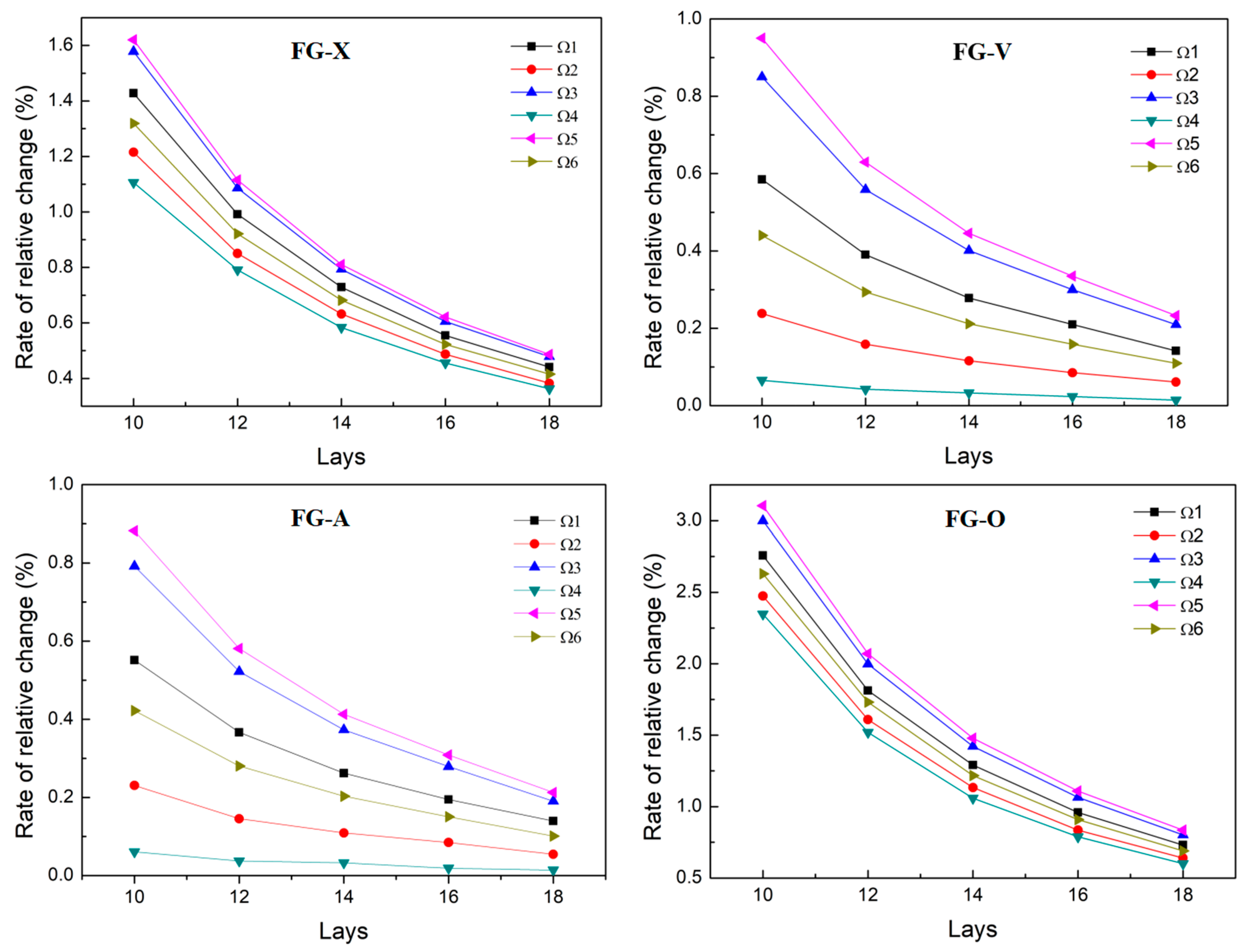
Then, we also investigated the convergence property of the natural frequencies of the cylindrical shell with the increase in the number of layers. The FG cylindrical shell clamped at both ends is taken as an example. The mechanical properties of the epoxy resin and GPLs are shown in Table 1. The GPL reinforcements are distributed in the epoxy matrix in the forms of FG-X, FG-V, FG-A, and FG-O, respectively. The mass fraction of GPL reinforcement is 1%. With the number of layers as the independent variable, the natural frequencies of the FG cylindrical shell were calculated for different layers. For four forms of FG GPL distributions, the corresponding relationships between the natural frequencies and the number of layers are depicted in Figure 4. We find that the variation rates of natural frequencies in the first six orders decrease gradually with the increase in the number of layers. When the number of layers is 16, both rates of change for the natural frequencies of the FG-V and FG-A composite cylindrical shells are less than 0.4%, whereas the rate of change for the natural frequencies of the FG-X and FG-O composite cylindrical shells are less than 0.7% and 1.25%, respectively. It can be seen that the natural frequencies of the FG cylindrical shell with 16 layers can be considered to have converged, which can meet the substitution of continuous FGMs. Therefore, all FG cylindrical shells are set to the form of 16 layers in the following sections.
4.2. Mode Comparison
In order to ensure the convergence and accuracy of the solution procedure proposed in this paper, we need to further compare the accuracy of the theoretical calculation with the finite element results of the FG three-phase composite cylindrical shells under different boundary conditions.
First, the theoretical results of the natural frequencies and mode shapes of the FG two-phase composite cylindrical shells are compared with the finite element results. The GPL reinforcement is distributed in the epoxy matrix in the form of FG-X, with a mass fraction of 1%. These results are shown in Table 6, Table 7 and Table 8. By analyzing and comparing the above three tables, we find that, overall, the theoretical values of the first six orders of natural frequencies of the FG cylindrical shell are very close to the finite element results. The difference between the theoretical and finite element results of the natural frequencies of the FG cylindrical shell with solidly supported boundary conditions at both ends is minimal. The errors of the first three orders of natural frequencies are 0.43%, 0.75%, and 0.32%, respectively. In addition, the first six orders of the modal shapes of the FG cylindrical shell are consistent with the finite element results.
Then, we calculated the natural vibration characteristics of carbon fiber-reinforced composite laminated cylindrical shells. The theoretical results are compared with the finite element results, and the results are organized in Table 9, Table 10 and Table 11. The geometrical parameters and three boundary conditions of the cylindrical shell were kept the same as above. The volume fraction of carbon fibers (Vf) was 10%, and the layup angle was [16]. From Table 9, Table 10 and Table 11, we find that the errors of the theoretical values of the first-order natural frequency of the composite laminated cylindrical shells compared with the finite element results under the three boundary conditions are kept below 0.1%. In addition, for the three boundary conditions, the theoretical results of axial wave number and circumferential wave number of the first six orders of vibrations of the composite laminated cylindrical shell are completely consistent with the finite element results.
Finally, the theoretical and finite element results for the natural frequency and mode shapes of the FG three-phase composite cylindrical shell are compared. The mechanical properties of the GPLs and the carbon fibers are shown in Table 1 and Table 3, respectively. The GPL reinforcements are distributed in the matrix in the form of FG-X to form the HM, and the carbon fiber reinforcements are distributed in the form of lamination laying in the HM. The GPLs mass fraction (WGpl) is 1%, and the content of carbon fibers (Vf) is 10%, and the carbon fibers layup angle is . The results are shown in Table 12, Table 13 and Table 14. It can be seen that the theoretical values of the first six orders of the natural frequencies are much closer to the finite element results. Among them, except for the second-order natural frequency under the free boundary conditions at both ends, the errors of the first three orders of the natural frequencies of both do not exceed 0.36%. In addition, the theoretical results of the first six orders of the mode shapes of the three-phase composite cylindrical shell are in complete agreement with the finite element results. Thus, it is verified that the calculation method of this paper applies to the FG three-phase composite cylindrical shell and has good accuracy.
The advantage of the calculation method in this paper is that it is possible to calculate the natural frequencies and mode shapes of not only the FG three-phase composite cylindrical shell but also two-phase composite and homogeneous cylindrical shells because the two-phase composite and homogeneous forms are special cases of the three-phase materials, and we only need to change the parameter settings.
5. Free Vibrations of a Three-Phase Composite Cylindrical Shell
In this section, we first study the natural frequencies of the FG three-phase composite cylindrical shell corresponding to different boundary conditions to analyze the effect of spring stiffness. Then, we further investigate the effects of GPL reinforcement and carbon fiber reinforcement on the natural frequencies of the FG three-phase composite cylindrical shell in depth. The mechanical properties of the epoxy matrix, GPL reinforcement, and carbon fibers are shown in Table 1, Table 2 and Table 3, respectively.
5.1. Effects of Boundary Spring Stiffness on the Natural Frequencies
At the beginning of this section, we first investigate the effects of artificial boundary spring stiffness on the natural frequencies of the FG three-phase composite cylindrical shell. For this, the GPLs were distributed in the form of FG-X, the WGpl was 1%, the Vf was 10%, and the carbon fiber layup angle was . The artificial boundary spring stiffness was chosen as the independent variable to calculate the natural frequencies of the cylindrical shell for the spring stiffness values, k, at both ends of 0, , , , , and , respectively, as shown in Figure 5. We find that the first six orders of the natural frequencies of the cylindrical shell increase with the increase in the spring stiffness at both ends and then converge to a fixed value. The first six orders of the natural frequencies of the cylindrical shell are approximately the same for a spring stiffness of 0: , and , respectively. When the spring stiffness increases from to , the first six orders of the natural frequencies increase significantly at the same time. When the spring stiffness is increased to , the relative difference between the first three orders of the natural frequencies of the cylindrical shell with a spring stiffness of are only 0.03%, 0.02%, and 0.03%, respectively. Since the relative difference between the two natural frequencies is small enough, the natural frequencies can be considered to have converged. The spring stiffness can be taken as the clamped boundary condition at both ends.
Then, we studied the natural frequencies of the FG three-phase composite cylindrical shell under three types of traditional boundary conditions by setting the corresponding artificial boundary spring stiffness value. The three-phase composite material is the same as above. The results are shown in Figure 6.
The first six orders of the natural frequencies of the FG three-phase composite cylindrical shell are highest under the clamped boundary conditions at both ends. Under the simply supported boundary conditions at both ends, the first six orders of the natural frequencies of the cylindrical shell are slightly lower than those under the clamped boundary conditions at both ends, and the maximum relative difference between the two is only 6.8%. In the free boundary condition at both ends, the first six orders of the natural frequencies of the cylindrical shell are much lower than those of the other two boundary conditions, and the relative difference between the natural frequencies of the cylindrical shell under the clamped boundary condition at both ends and the simply supported boundary condition at both ends is 52.5% and 49.6%, respectively.
5.2. Effects of Reinforcements on the Natural Frequencies
We first chose GPL content as the independent variable. The natural frequencies of the FG three-phase composite cylindrical shell were calculated to analyze the effects of GPL content on the natural frequencies of the cylindrical shell. The results are shown in Figure 7. For this, the GPLs were uniformly distributed, the boundary conditions were clamped at both ends, the content of carbon fiber was 10%, and the carbon fiber layup angle was .
In Figure 7, we find that the increase in GPL content significantly improves the first six orders of the natural frequencies of the FG three-phase composite cylindrical shell. During the gradual increase in WGpl from 0 to 1.5%, the first-order natural frequency increased by 104.092 Hz, with a total increase of 85.75% and a gradually decreasing gradient. In general, the increase in GPL content has a greater effect on the third-order natural frequency than the first two orders of the natural frequencies of the FG three-phase composite cylindrical shell, and this has the greatest effect on the fifth-order natural frequencies of this cylindrical shell. In Figure 7, the second and fifth orders of the natural frequencies show an interesting and important pattern. When the WGpl is 0.25%, the turning point of the relationship curve appears, and the second and third orders of the natural frequencies are very close to each other, with a difference of only 1.65%. When the WGpl is 0.75%, the relationship curve also has a turning point, and the fifth and sixth orders of the natural frequencies are very close, with a difference of only 0.22%.
Next, the influences of the GPL FG distributions on the natural frequencies of the FG three-phase composite cylindrical shell were studied when WGpl was 1%. The GPL FG distribution was set as the independent variable, where the GPLs were distributed in four forms: X, V, A, and O, respectively. The natural frequencies of the cylindrical shell are calculated for the four GPL FG distributions.
Figure 8 shows the effect of the GPL functional gradient form on the natural frequency of the FG three-phase composite cylindrical shell. It can be observed that the first six orders of the natural frequencies of this cylindrical shell with the X-type GPL FG distributions (FG-X) are the highest. In contrast, the first six orders of the natural frequencies of the cylindrical shell with the O-type GPL FG distributions (FG-O) are the lowest. Specifically, for the first three orders of natural frequencies of the cylindrical shell, the natural frequencies of the FG-X type increased by 16.38%, 24.51%, and 10.84% compared to the FG-O type. Moreover, the first six orders of the natural frequencies of the cylindrical shell with the FG-A and FG-V types are in between the FG-X and FG-O types. The reason may be that the distribution of GPLs is concentrated on the upper and lower surfaces of the FG three-phase composite cylindrical shell, resulting in a higher natural frequency, whereas the distribution of GPLs is concentrated in the middle plane of the cylindrical shell structure, resulting in a lower natural frequency.
Then, we investigated the effects of carbon fiber volume fraction (Vf) on the natural frequencies of the FG three-phase composite cylindrical shell under the clamped-clamped boundary condition. The WGpl was 1%. The carbon fiber layup angle was . With the volume fraction of carbon fiber as the independent variable, the natural frequencies of the cylindrical shell are calculated, and the results are shown in Figure 9. For this, the GPLs were distributed in the epoxy matrix in the form of FG-X, FG-V, FG-A, and FG-O, respectively.
In Figure 9a, when the GPLs are distributed in the epoxy matrix in the form of FG-X, the first six orders of the natural frequencies all increase significantly with the increase in carbon fiber content. Among them, the first-order natural frequency increases from 212 Hz to 277 Hz, corresponding to an increase of 30.66%. The second and third orders of the natural frequencies are very close to each other. When the carbon fiber volume fractions are 0.3 and 0.4, the differences between the second and third orders of the natural frequencies of the cylindrical shell are only 2.08% and 1.57%, respectively.
By using Figure 9b,c, we can study the influences of different carbon fiber volume fractions on the natural frequencies of the cylindrical shell when the GPLs are distributed in the epoxy matrix in the form of FG-V and FG-A, respectively. The natural frequencies of the cylindrical shell with FG-A are slightly higher than those with FG-V for any given carbon fiber volume fraction. However, the distribution patterns of the first four orders of the natural frequencies are similar in both FG distributions, and the first-order natural frequency increases gradually and almost linearly. The second-order natural frequency gradually approaches the third-order natural frequency with the increase in the carbon fiber volume fraction. When the carbon fiber volume fractions are 0.3, 0.4, and 0.5, the differences between the second and third orders of the natural frequencies of the cylindrical shell with the FG-A type are only 2.07%, 0.90%, and 0.71%, respectively. In the FG-A HM, the second and third orders of the natural frequencies are very close when the carbon fiber volume fractions are 0.4 and 0.5, with differences of only 0.91% and 0.71%, respectively.
Figure 9d shows the effects of carbon fiber volume fraction on the natural frequencies of the cylindrical shell when the HM is an FG-O form. During the process of increasing the carbon fiber volume fraction from 0.1 to 0.2, the natural frequency increases significantly. When the carbon fiber volume fraction is 0.5, the second and third orders of the natural frequencies are very close to each other, with a difference of only 3.19%. The fifth and sixth orders of the natural frequencies are also very close to each other when the carbon fiber volume fraction is 0.3 and 0.4, differing by 6.50% and 6.59%, respectively.
Finally, Figure 10 represents the relationship between the carbon fiber layup angle and the natural frequency of the cylindrical shell reinforced. The boundary conditions are the same as above. The Vf was 0.1. In this paper, the direction of carbon fibers along the axial direction of the cylindrical shell is noted as the 0° direction of the carbon fibers. The carbon fiber layup angle was taken as the independent variable, where the carbon fiber layup angles are , , , , , and .
In Figure 10, it can be seen that the highest value is found in the first six orders of the natural frequencies of the three-phase composite cylindrical shell reinforced with as the carbon fiber layup angle. The lowest values are found in the first six orders of the three-phase composite cylindrical shell reinforced with as the carbon fiber layup angle. The different carbon fiber layup angles have little effect on the first, third, fifth, and sixth orders of the natural frequencies. The second and fourth orders of the natural frequencies change significantly with the change in carbon fiber layup angles. Moreover, some interesting and important results can be found; for the FG three-phase composite cylindrical shell, carbon fibers laid at symmetrical angles—90° at the top and bottom surfaces of the shell and 0° at the middle surface—result in the highest second and fourth orders of the natural frequencies. On the contrary, laying 0° carbon fibers at the top and bottom surfaces of the cylindrical shell and 90° carbon fibers at the middle surface results in the lowest second and fourth orders of the natural frequencies.
6. Conclusions
This paper focuses on the free vibrations of a new FG three-phase composite cylindrical shell reinforced synergistically with GPLs and carbon fibers. This new FG three-phase composite cylindrical shell integrates the advantages of a carbon fiber-reinforced composite structure and an FG-reinforced composite structure. In this paper, the equivalent mechanical properties of the FG three-phase composite material are calculated. We derive the governing equations for the free vibrations of the FG three-phase composite cylindrical shell, and the analytical solutions of the natural frequencies of this three-phase composite cylindrical shell are obtained. On this basis, we deeply analyzed the influences of different factors on the free vibrations of FG three-phase composite cylindrical shells reinforced synergistically with GPLs and carbon fibers, including the boundary spring stiffness, GPL mass fraction, GPL FG distributions, carbon fiber content, and the carbon fiber layup angle. The following conclusions are obtained:
- (1)
- Boundary spring stiffness has a significant impact on the natural frequencies of the three-phase composite cylindrical shell. The natural frequencies of the three-phase composite cylindrical shell reach a maximum under the sufficiently large spring stiffness corresponding to the boundary condition when clamped at both ends. When the boundary spring stiffness is 0, that is, the corresponding free boundary condition is at both ends, then the natural frequencies of the FG three-phase composite cylindrical shell is minimum, which is far lower than the natural frequency of the three-phase composite cylindrical shell under the other two boundary conditions of clamped and simple-support.
- (2)
- The synergistic enhancement of GPLs and carbon fibers can greatly increase the natural frequencies of the composite cylindrical shell. Among these, GPLs can play a more obvious strengthening role than carbon fibers. We know that too many GPLs may increase the possibility of aggregation, but only a small amount of GPLs can significantly enhance the composite cylindrical shell.
- (3)
- The four FG GPL distributions have different effects on the natural frequencies of the FG three-phase composite cylindrical shell. When GPLs are distributed in the X-type FG form, each order of the natural frequency of the three-phase composite cylindrical shell is higher than those of the other three FG distributions, whereas each order of the natural frequency of the three-phase composite cylindrical shell is lower when GPLs are distributed in the O-type FG form.
- (4)
- Carbon fiber is another important reinforcement material in the three-phase composite cylindrical shell, and its laying angle can also significantly affect the natural frequencies of the three-phase composite cylindrical shell. If carbon fibers are distributed along the axis of this cylindrical shell, each order of the natural frequency of the three-phase composite cylindrical shell is higher, whereas each order of the natural frequency of the three-phase composite cylindrical shell is lower when the carbon fibers are distributed along the circumferential direction.
Author Contributions
The contributions of all authors are given below. Conceptualization, T.L. and Y.Z.; methodology, T.L. and J.D.; software, T.L. and J.D.; validation, J.D.; formal analysis, J.D.; investigation, T.L.; resources, Y.Z.; data curation, J.D.; writing—original draft preparation, J.D.; writing—review and editing, T.L.; visualization, Y.Z.; supervision, Y.Z. and Y.Q.; project administration, T.L. and Y.Q.; funding acquisition, T.L. and Y.Q. All authors have read and agreed to the published version of the manuscript.
Funding
The authors gratefully acknowledge the support of the National Natural Science Foundation of China (NNSFC) through Grant No.s 12202018, 12332001, and 12322202, the Funding Projects of the Beijing Institute of Graphic Communication through Grant No.s 20190123083 and 27170123038, the support of the China Postdoctoral Science Foundation through Grant No.s 2021TQ0021 and 2022M710280, and the Funding Project for Postdoctoral Research from Beijing City and Chaoyang District.
Data Availability Statement
The data presented in this study are available on request from the corresponding author.
Conflicts of Interest
The authors declare that there is no conflict of interests regarding the publication of this paper.
References
- Gagné, M.; Therriault, D. Lightning strike protection of composites. Prog. Aerosp. Sci. 2014, 64, 1–16. [Google Scholar] [CrossRef]
- Katunin, A.; Krukiewicz, K.; Herega, A.; Catalanotti, G. Concept of a conducting composite material for lightning strike protection. Adv. Mater. Sci. 2016, 16, 32–46. [Google Scholar] [CrossRef]
- Aluko, O.; Gowtham, S.; Odegard, G.M. Multiscale modeling and analysis of graphene nanoplatelet/carbon fiber/epoxy hybrid composite. Compos. Part B Eng. 2017, 131, 82–90. [Google Scholar] [CrossRef]
- Kumar, A.; Sharma, K.; Dixit, A.R. Carbon nanotube- and graphene-reinforced multiphase polymeric composites: Review on their properties and applications. J. Mater. Sci. 2020, 55, 2682–2724. [Google Scholar] [CrossRef]
- Alemour, B.; Badran, O.; Hassan, M.R. A review of using conductive composite materials in solving lightening strike and ice accumulation problems in aviation. J. Aerosp. Technol. Manag. 2019, 11, e1919. [Google Scholar] [CrossRef]
- Yadav, R.; Tirumali, M.; Wang, X.; Naebe, M.; Kandasubramanian, B. Polymer composite for antistatic application in aerospace. Def. Technol. 2020, 16, 107–118. [Google Scholar] [CrossRef]
- Zhang, B.; Patlolla, V.R.; Chiao, D.; Kalla, D.K.; Misak, H.; Asmatulu, R. Galvanic corrosion of Al/Cu meshes with carbon fibers and graphene and ITO-based nanocomposite coatings as alternative approaches for lightning strikes. Int. J. Adv. Manuf. Technol. 2013, 67, 1317–1323. [Google Scholar] [CrossRef]
- Karch, C.; Metzner, C. Lightning protection of carbon fibre reinforced plastics—An overview. In Proceedings of the 2016 33rd International Conference on Lightning Protection (ICLP), Estoril, Portugal, 25–30 September 2016; pp. 1–8. [Google Scholar]
- Wang, X.J. Prospects for the future development of China’s space transportation system. Space Sci. Technol. 2021, 2021, 9769856. [Google Scholar] [CrossRef]
- Cai, M.H.; Yang, T.; Li, H.W.; Yang, H.X.; Han, J.W. Experimental and simulation study on shielding performance of developed hydrogenous composites. Space Sci. Technol. 2022, 2022, 9754387. [Google Scholar] [CrossRef]
- Liu, T.; Zhang, W.; Mao, J.J.; Zheng, Y. Nonlinear breathing vibrations of eccentric rotating composite laminated circular cylindrical shell subjected to temperature, rotating speed and external excitations. Mech. Syst. Signal Process. 2019, 127, 463–498. [Google Scholar] [CrossRef]
- Liu, T.; Zhang, W.; Zheng, Y.; Zhang, Y.F.; Zhao, W. Potential well evolution and metastable dynamics of bistable asymmetric laminated composite square shallow shell under external and parametric excitations. Compos. Struct. 2022, 280, 114936. [Google Scholar] [CrossRef]
- Wang, Y.Q.; Ye, C.; Zu, J.W. Nonlinear vibration of metal foam cylindrical shells reinforced with graphene platelets. Aerosp. Sci. Technol. 2019, 85, 359–370. [Google Scholar] [CrossRef]
- Chai, Q.; Wang, Y.Q. Traveling wave vibration of graphene platelet reinforced porous joined conical-cylindrical shells in a spinning motion. Eng. Struct. 2022, 252, 113718. [Google Scholar] [CrossRef]
- Zhao, S.Y.; Zhao, Z.; Yang, Z.C.; Ke, L.L.; Kitipornchai, S.; Yang, J. Functionally graded graphene reinforced composite structures: A review. Eng. Struct. 2020, 210, 110399. [Google Scholar] [CrossRef]
- Reddy, J.N. Mechanics of Laminated Composite Plates and Shells: Theory and Analysis; CRC Press: Boca Raton, FL, USA, 2004. [Google Scholar]
- Amabili, M.; Fletcher, N.H. Nonlinear Vibrations and Stability of Shells and Plates; Cambridge University Press: Cambridge, UK, 2009. [Google Scholar]
- Alijani, F.; Amabili, M. Non-linear vibrations of shells: A literature review from 2003 to 2013. Int. J. Non-Linear Mech. 2014, 58, 233–257. [Google Scholar] [CrossRef]
- Zhang, W.; Yang, S.W.; Mao, J.J. Nonlinear radial breathing vibrations of CFRP laminated cylindrical shell with non-normal boundary conditions subjected to axial pressure and radial line load at two ends. Compos. Struct. 2018, 190, 52–78. [Google Scholar] [CrossRef]
- Zhang, W.; Liu, T.; Xi, A.; Wang, Y.N. Resonant responses and chaotic dynamics of composite laminated circular cylindrical shell with membranes. J. Sound Vib. 2018, 423, 65–99. [Google Scholar] [CrossRef]
- Li, C.; Li, P.; Zhong, B.; Miao, X. Large-amplitude vibrations of thin-walled rotating laminated composite cylindrical shell with arbitrary boundary conditions. Thin-Walled Struct. 2020, 156, 106966. [Google Scholar] [CrossRef]
- Guo, C.C.; Liu, T.; Bin, Q.; Wang, Q.S.; Wang, A.L. Free vibration analysis of coupled structures of laminated composite conical, cylindrical and spherical shells based on the spectral-Tchebychev technique. Compos. Struct. 2022, 281, 114965. [Google Scholar] [CrossRef]
- Tang, D.; Yao, X.L.; Wu, G.X.; Peng, Y. Free and forced vibration analysis of multi-stepped circular cylindrical shells with arbitrary boundary conditions by the method of reverberation-ray matrix. Thin-Walled Struct. 2017, 116, 154–168. [Google Scholar] [CrossRef]
- Wang, Q.S.; Shao, D.; Qin, B. A simple first-order shear deformation shell theory for vibration analysis of composite laminated open cylindrical shells with general boundary conditions. Compos. Struct. 2018, 184, 211–232. [Google Scholar] [CrossRef]
- He, D.; Shi, D.Y.; Wang, Q.S.; Shuai, C.J. Wave based method (WBM) for free vibration analysis of cross-ply composite laminated cylindrical shells with arbitrary boundaries. Compos. Struct. 2019, 213, 284–298. [Google Scholar] [CrossRef]
- Shi, D.Y.; He, D.Z.; Wang, Q.S.; Ma, C.L.; Shu, H.S. Wave Based Method for Free Vibration Analysis of Cross-Ply Composite Laminated Shallow Shells with General Boundary Conditions. Materials 2019, 12, 3808. [Google Scholar] [CrossRef] [PubMed]
- He, D.Z.; Shi, D.Y.; Wang, Q.S.; Ma, C.L. A unified power series method for vibration analysis of composite laminate conical, cylindrical shell and annular plate. Structures 2021, 29, 305–327. [Google Scholar] [CrossRef]
- Wang, A.W.; Chen, H.Y.; Hao, Y.X.; Zhang, W. Vibration and bending behavior of functionally graded nanocomposite doubly-curved shallow shells reinforced by graphene nanoplatelets. Results Phys. 2018, 9, 550–559. [Google Scholar] [CrossRef]
- Liu, D.Y.; Kitipornchai, S.; Chen, W.Q.; Yang, J. Three-dimensional buckling and free vibration analyses of initially stressed functionally graded graphene reinforced composite cylindrical shell. Compos. Struct. 2018, 189, 560–569. [Google Scholar] [CrossRef]
- Thang, P.T.; Do, D.T.T.; Nguyen, T.T.; Lee, J.; Nguyen-Thoi, T. Free vibration characteristic analysis of functionally graded shells with porosity and neutral surface effects. Adv. Mech. 2022, 255, 111377. [Google Scholar] [CrossRef]
- Wang, Q.S.; Pang, F.Z.; Qin, B.; Liang, Q. A unified formulation for free vibration of functionally graded carbon nanotube reinforced composite spherical panels and shells of revolution with general elastic restraints by means of the Rayleigh-Ritz method. Polym. Compos. 2018, 39, E924–E944. [Google Scholar] [CrossRef]
- Qin, Z.Y.; Pang, X.J.; Safaei, B.; Chu, F.L. Free vibration analysis of rotating functionally graded CNT reinforced composite cylindrical shells with arbitrary boundary conditions. Compos. Struct. 2019, 220, 847–860. [Google Scholar] [CrossRef]
- Sobhani, E.; Masoodi, A.R.; Ahmadi-Pari, A.R. Vibration of FG-CNT and FG-GNP sandwich composite coupled Conical-Cylindrical-Conical shell. Compos. Struct. 2021, 273, 114281. [Google Scholar] [CrossRef]
- Abedini Baghbadorani, A.; Kiani, Y. Free vibration analysis of functionally graded cylindrical shells reinforced with graphene platelets. Compos. Struct. 2021, 276, 114546. [Google Scholar] [CrossRef]
- Ghamkhar, M.; Naeem, M.N.; Imran, M.; Soutis, C. Vibration Analysis of a Three-Layered FGM Cylindrical Shell Including the Effect of Ring Support. Open Phys. 2019, 17, 587–600. [Google Scholar] [CrossRef]
- Xie, F.; Tang, J.Y.; Wang, A.L.; Shuai, C.J.; Wang, Q.S. Free vibration of functionally graded carbon nanotube reinforced composite cylindrical panels with general elastic supports. Curved Layer. Struct. 2018, 5, 95–115. [Google Scholar] [CrossRef]
- Van Do, V.N.; Lee, C.H. Bézier extraction based isogeometric analysis for bending and free vibration behavior of multilayered functionally graded composite cylindrical panels reinforced with graphene platelets. Int. J. Mech. Sci. 2020, 183, 105744. [Google Scholar] [CrossRef]
- Khoa, N.D.; Anh, V.M.; Duc, N.D. Nonlinear dynamic response and vibration of functionally graded nanocomposite cylindrical panel reinforced by carbon nanotubes in thermal environment. J. Sandw. Struct. Mater. 2019, 23, 852–883. [Google Scholar] [CrossRef]
- Twinkle, C.M.; Pitchaimani, J. Free vibration and stability of graphene platelet reinforced porous nano-composite cylindrical panel: Influence of grading, porosity and non-uniform edge loads. Eng. Struct. 2021, 230, 111670. [Google Scholar]
- Rezaiee-Pajand, M.; Sobhani, E.; Masoodi, A.R. Free vibration analysis of functionally graded hybrid matrix/fiber nanocomposite conical shells using multiscale method. Aerosp. Sci. Technol. 2020, 105, 105998. [Google Scholar] [CrossRef]
- Ebrahimi, F.; Habibi, S. Nonlinear eccentric low-velocity impact response of a polymer-carbon nanotube-fiber multiscale nanocomposite plate resting on elastic foundations in hygrothermal environments. Mech. Adv. Mater. Struct. 2018, 25, 425–438. [Google Scholar] [CrossRef]
- Gholami, R.; Ansari, R. Nonlinear bending of third-order shear deformable carbon nanotube/fiber/polymer multiscale laminated composite rectangular plates with different edge supports. Eur. Phys. J. Plus 2018, 133, 282. [Google Scholar] [CrossRef]
- Arani, A.G.; Zarei, H.B.; Eskandari, M.; Pourmousa, P. Vibration behavior of visco-elastically coupled sandwich beams with magnetorheological core and three-phase carbon nanotubes/fiber/polymer composite facesheets subjected to external magnetic field. J. Sandw. Struct. Mater. 2019, 21, 2194–2218. [Google Scholar] [CrossRef]
- Karimiasl, M.; Ebrahimi, F.; Mahesh, V. Nonlinear free and forced vibration analysis of multiscale composite doubly curved shell embedded in shape-memory alloy fiber under hygrothermal environment. J. Vib. Control 2019, 25, 1945–1957. [Google Scholar] [CrossRef]
- Yousefi, A.H.; Memarzadeh, P.; Afshari, H.; Hosseini, S.J. Agglomeration effects on free vibration characteristics of three-phase CNT/polymer/fiber laminated truncated conical shells. Thin-Walled Struct. 2020, 157, 107077. [Google Scholar] [CrossRef]
- Sobhani, E.; Moradi-Dastjerdi, R.; Behdinan, K.; Masoodi, A.R.; Ahmadi-Pari, A.R. Multifunctional trace of various reinforcements on vibrations of three-phase nanocomposite combined hemispherical-cylindrical shells. Compos. Struct. 2022, 279, 114798. [Google Scholar] [CrossRef]
- Amabili, M. Nonlinear vibrations of laminated circular cylindrical shells: Comparison of different shell theories. Compos. Struct. 2011, 94, 207–220. [Google Scholar] [CrossRef]
- Sobhani, E.; Masoodi, A.R. Natural frequency responses of hybrid polymer/carbon fiber/FG-GNP nanocomposites paraboloidal and hyperboloidal shells based on multiscale approaches. Aerosp. Sci. Technol. 2021, 119, 107111. [Google Scholar] [CrossRef]
- Abaimov, S.G.; Khudyakova, A.A.; Lomov, S.V. On the closed form expression of the Mori–Tanaka theory prediction for the engineering constants of a unidirectional fiber-reinforced ply. Compos. Struct. 2016, 142, 1–6. [Google Scholar] [CrossRef]
- Zhang, W.; Fang, Z.; Yang, X.D.; Liang, F. A series solution for free vibration of moderately thick cylindrical shell with general boundary conditions. Eng. Struct. 2018, 165, 422–440. [Google Scholar] [CrossRef]
- Dai, L.; Yang, T.; Du, J.; Li, W.L.; Brennan, M.J. An exact series solution for the vibration analysis of cylindrical shells with arbitrary boundary conditions. Appl. Acoust. 2013, 74, 440–449. [Google Scholar] [CrossRef]
Figure 1.
The FG three-phase composite cylindrical shell model reinforced synergistically with GPLs and carbon fibers.
Figure 1.
The FG three-phase composite cylindrical shell model reinforced synergistically with GPLs and carbon fibers.

Figure 2.
The model of the three-phase composite cylindrical shell under arbitrary boundary conditions in a column co-ordinate system.
Figure 2.
The model of the three-phase composite cylindrical shell under arbitrary boundary conditions in a column co-ordinate system.

Figure 3.
The distribution of membrane stress and bending moment in the boundary.

Figure 4.
The relationships between the number of layers and the rate of change for the natural frequencies of the FGM cylindrical shell.
Figure 4.
The relationships between the number of layers and the rate of change for the natural frequencies of the FGM cylindrical shell.

Figure 5.
The natural frequencies of the three-phase composite cylindrical shells corresponding to different boundary spring stiffness.
Figure 5.
The natural frequencies of the three-phase composite cylindrical shells corresponding to different boundary spring stiffness.

Figure 6.
The natural frequencies of the three-phase composite cylindrical shells under three types of boundary conditions.
Figure 6.
The natural frequencies of the three-phase composite cylindrical shells under three types of boundary conditions.

Figure 7.
The changes for natural frequencies of the three-phase composite cylindrical shells with the increase in GPL mass fraction.
Figure 7.
The changes for natural frequencies of the three-phase composite cylindrical shells with the increase in GPL mass fraction.

Figure 8.
The natural frequencies of the three-phase composite cylindrical shells corresponding to four forms of GPL FG distributions.
Figure 8.
The natural frequencies of the three-phase composite cylindrical shells corresponding to four forms of GPL FG distributions.

Figure 9.
The changes of the natural frequencies of the three-phase composite cylindrical shells with the increase in carbon fiber content. (a) FG-X three-phase composite cylindrical shell. (b) FG-V three-phase composite cylindrical shell. (c) FG-A three-phase composite cylindrical shell. (d) FG-O three-phase composite cylindrical shell.

Figure 10.
The natural frequencies of the three-phase composite cylindrical shells corresponding to six types of carbon fiber layup angles.
Figure 10.
The natural frequencies of the three-phase composite cylindrical shells corresponding to six types of carbon fiber layup angles.


Table 1.
The mechanical properties of the epoxy polymer; the GPLs are given.
| Material | |||
|---|---|---|---|
| 8551-7 epoxy polymer (matrix) | 4.08 | 0.38 | 1272 |
| Graphene platelets | 1010 | 0.186 | 1062.5 |
Table 2.
The geometrical properties of the GPLs are given.
| Material | |||
|---|---|---|---|
| Graphene platelets (GPLs) | 2.5 | 1.5 | 1.5 |
Table 3.
The mechanical properties of IM-7 carbon fiber are given.
| Material | |||||||
|---|---|---|---|---|---|---|---|
| Carbon fiber | 276.0 | 19.0 | 0.2 | 0.2 | 27.0 | 7.0 | 1780 |
Table 4.
The corresponding spring stiffness values of the arbitrary boundary conditions are listed.
| BC | Spring Stiffness | ||||
|---|---|---|---|---|---|
| F | 0 | 0 | 0 | 0 | 0 |
| S | 0 | ||||
| C | |||||
Table 5.
Comparisons of the theoretical results of the natural frequency of cylindrical shells under C-C boundary conditions with finite elements and the existing literature results. (L = 0.502 m; R = 0.0635 m; h = 0.00163 m; ρ = 7800 kg/m3; ν = 0.28; E = 2.1E + 11N/m2).
Table 5.
Comparisons of the theoretical results of the natural frequency of cylindrical shells under C-C boundary conditions with finite elements and the existing literature results. (L = 0.502 m; R = 0.0635 m; h = 0.00163 m; ρ = 7800 kg/m3; ν = 0.28; E = 2.1E + 11N/m2).
| n | Present | Dai et al. [51] | Abaqus | ||||
|---|---|---|---|---|---|---|---|
| M = 6 N = 6 | M = 8 N = 8 | M = 10 N = 10 | M = 12 N = 12 | M = 14 N = 14 | |||
| 1 | 905.1 | 901.9 | 900.6 | 899.8 | 899.2 | 896.6 | 900.5 |
| 2 | 922.91 | 915.8 | 911.9 | 909.4 | 907.5 | 898.2 | 900.9 |
| 3 | 1425.6 | 1414.0 | 1408.4 | 1404.9 | 1402.5 | 1388.9 | 1395.8 |
| 4 | 1502.3 | 1501.1 | 1500.6 | 1500.3 | 1501.6 | 1501.6 | 1516.3 |
| 5 | 1692.1 | 1685.1 | 1682.6 | 1681.1 | 1680.3 | 1676.0 | 1690.7 |
| 6 | 1911.3 | 1904.5 | 1899.8 | 1896.2 | 1893.4 | 1880.9 | 1883.2 |
| 7 | 2083.5 | 2060.7 | 2048.7 | 2041.4 | 2036.6 | 2014.1 | 2020.8 |
| 8 | 2144.4 | 2097.7 | 2080.4 | 2071.6 | 2064.9 | 2389.0 | 2064.7 |
| 9 | 2343.8 | 2269.0 | 2239.4 | 2223.3 | 2213.1 | 2472.6 | 2189.4 |
Table 6.
Modal comparisons of the X-type FG cylindrical shell under C-C boundary conditions are given.
Table 6.
Modal comparisons of the X-type FG cylindrical shell under C-C boundary conditions are given.
| C-C | Mode No. | |||||
|---|---|---|---|---|---|---|
| 1 | 2 | 3 | 4 | 5 | 6 | |
| Present |  |  |  |  |  |  |
| Abaqus |  |  |  |  |  |  |
| Present | 187.46 | 204.85 | 229.20 | 268.78 | 338.52 | 343.53 |
| Abaqus | 188.27 | 206.40 | 229.94 | 273.04 | 339.18 | 346.36 |
| Error | 0.43% | 0.75% | 0.32% | 1.56% | 0.19% | 0.81% |
Table 7.
Modal comparisons of the X-type FG cylindrical shell under S-S boundary conditions are given.
Table 7.
Modal comparisons of the X-type FG cylindrical shell under S-S boundary conditions are given.
| S-S | Mode No. | |||||
|---|---|---|---|---|---|---|
| 1 | 2 | 3 | 4 | 5 | 6 | |
| Present |  |  |  |  |  |  |
| Abaqus |  |  |  |  |  |  |
| Present | 175.92 | 194.93 | 219.61 | 261.31 | 317.10 | 327.30 |
| Abaqus | 176.93 | 196.88 | 220.36 | 266.12 | 319.96 | 329.99 |
| Error | 0.57% | 0.99% | 0.34% | 1.81% | 0.89% | 0.81% |
Table 8.
Modal comparisons of the X-type FG cylindrical shell under F-F boundary conditions are given.
Table 8.
Modal comparisons of the X-type FG cylindrical shell under F-F boundary conditions are given.
| F-F | Mode No. | |||||
|---|---|---|---|---|---|---|
| 1 | 2 | 3 | 4 | 5 | 6 | |
| Present |  |  |  |  |  |  |
| Abaqus |  |  |  |  |  |  |
| Present | 25.80 | 36.83 | 72.72 | 87.11 | 138.76 | 154.43 |
| Abaqus | 25.91 | 33.90 | 73.40 | 86.03 | 141.09 | 155.56 |
| Error | 0.42% | 7.95% | 0.92% | 1.25% | 1.65% | 0.72% |
Table 9.
Modal comparisons of the composite laminated cylindrical shell under C-C boundary conditions are given.
Table 9.
Modal comparisons of the composite laminated cylindrical shell under C-C boundary conditions are given.
| C-C | Mode No. | |||||
|---|---|---|---|---|---|---|
| 1 | 2 | 3 | 4 | 5 | 6 | |
| Present |  |  |  |  |  |  |
| Abaqus |  |  |  |  |  |  |
| Present | 121.39 | 137.84 | 147.07 | 202.43 | 203.95 | 226.69 |
| Abaqus | 121.34 | 137.82 | 147.14 | 202.54 | 204.37 | 226.61 |
| Error | 0.04% | 0.01% | 0.05% | 0.05% | 0.21% | 0.04% |
Table 10.
Modal comparisons of the composite laminated cylindrical shell under S-S boundary conditions are given.
Table 10.
Modal comparisons of the composite laminated cylindrical shell under S-S boundary conditions are given.
| S-S | Mode No. | |||||
|---|---|---|---|---|---|---|
| 1 | 2 | 3 | 4 | 5 | 6 | |
| Present |  |  |  |  |  |  |
| Abaqus |  |  |  |  |  |  |
| Present | 113.54 | 130.46 | 141.21 | 198.41 | 199.96 | 203.82 |
| Abaqus | 113.56 | 130.47 | 141.37 | 198.50 | 200.50 | 203.81 |
| Error | 0.02% | 0.01% | 0.11% | 0.04% | 0.27% | 0.01% |
Table 11.
Modal comparisons of the composite laminated cylindrical shell under F-F boundary condition are given.
Table 11.
Modal comparisons of the composite laminated cylindrical shell under F-F boundary condition are given.
| F-F | Mode No. | |||||
|---|---|---|---|---|---|---|
| 1 | 2 | 3 | 4 | 5 | 6 | |
| Present |  |  |  |  |  |  |
| Abaqus |  |  |  |  |  |  |
| Present | 21.70 | 24.12 | 60.94 | 64.29 | 115.77 | 119.55 |
| Abaqus | 21.72 | 23.11 | 61.02 | 63.85 | 116.05 | 119.51 |
| Error | 0.09% | 4.37% | 0.13% | 0.69% | 0.24% | 0.03% |
Table 12.
Modal comparisons of the FG three-phase composite cylindrical shell under C-C boundary condition are given.
Table 12.
Modal comparisons of the FG three-phase composite cylindrical shell under C-C boundary condition are given.
| C-C | Mode No. | |||||
|---|---|---|---|---|---|---|
| 1 | 2 | 3 | 4 | 5 | 6 | |
| Present |  |  |  |  |  |  |
| Abaqus |  |  |  |  |  |  |
| Present | 212.30 | 239.63 | 253.98 | 320.21 | 377.26 | 390.48 |
| Abaqus | 211.71 | 238.76 | 253.71 | 319.13 | 377.33 | 388.34 |
| Error | 0.28% | 0.36% | 0.11% | 0.34% | 0.02% | 0.55% |
Table 13.
Modal comparisons of the FG three-phase composite cylindrical shell under S-S boundary condition are given.
Table 13.
Modal comparisons of the FG three-phase composite cylindrical shell under S-S boundary condition are given.
| S-S | Mode No. | |||||
|---|---|---|---|---|---|---|
| 1 | 2 | 3 | 4 | 5 | 6 | |
| Present |  |  |  |  |  |  |
| Abaqus |  |  |  |  |  |  |
| Present | 200.48 | 229.86 | 243.67 | 313.04 | 359.15 | 367.91 |
| Abaqus | 200.22 | 229.37 | 243.59 | 312.35 | 357.71 | 367.27 |
| Error | 0.13% | 0.21% | 0.03% | 0.22% | 0.40% | 0.17% |
Table 14.
Modal comparisons of the FG three-phase composite cylindrical shell under F-F boundary condition are given.
Table 14.
Modal comparisons of the FG three-phase composite cylindrical shell under F-F boundary condition are given.
| F-F | Mode No. | |||||
|---|---|---|---|---|---|---|
| 1 | 2 | 3 | 4 | 5 | 6 | |
| Present |  |  |  |  |  |  |
| Abaqus |  |  |  |  |  |  |
| Present | 32.00 | 41.84 | 90.11 | 102.85 | 171.76 | 185.56 |
| Abaqus | 32.01 | 38.88 | 90.17 | 101.3 | 172.07 | 184.95 |
| Error | 0.03% | 7.07% | 0.07% | 1.51% | 0.18% | 0.33% |
Disclaimer/Publisher’s Note: The statements, opinions and data contained in all publications are solely those of the individual author(s) and contributor(s) and not of MDPI and/or the editor(s). MDPI and/or the editor(s) disclaim responsibility for any injury to people or property resulting from any ideas, methods, instructions or products referred to in the content. |
© 2023 by the authors. Licensee MDPI, Basel, Switzerland. This article is an open access article distributed under the terms and conditions of the Creative Commons Attribution (CC BY) license (https://creativecommons.org/licenses/by/4.0/).
Share and Cite
MDPI and ACS Style
Liu, T.; Duan, J.; Zheng, Y.; Qian, Y. Free Vibrations of a New Three-Phase Composite Cylindrical Shell. Aerospace 2023, 10, 1007. https://doi.org/10.3390/aerospace10121007
AMA Style
Liu T, Duan J, Zheng Y, Qian Y. Free Vibrations of a New Three-Phase Composite Cylindrical Shell. Aerospace. 2023; 10(12):1007. https://doi.org/10.3390/aerospace10121007
Chicago/Turabian StyleLiu, Tao, Jinqiu Duan, Yan Zheng, and Yingjing Qian. 2023. "Free Vibrations of a New Three-Phase Composite Cylindrical Shell" Aerospace 10, no. 12: 1007. https://doi.org/10.3390/aerospace10121007
Note that from the first issue of 2016, this journal uses article numbers instead of page numbers. See further details here.