
A Study on a Vitiated Air Heater for a Direct-Connect Scramjet Combustor and Preliminary Test on the Scramjet Combustor Ignition

Abstract
:1. Introduction
2. Experimental Apparatus
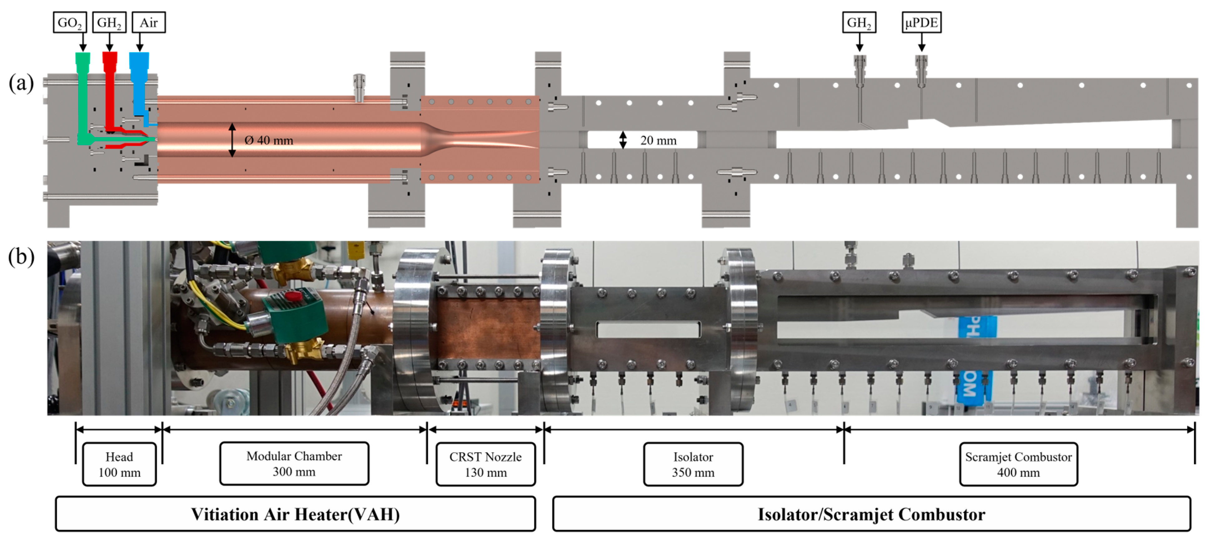
2.1. Vitiation-Air-Heater Experimental Model
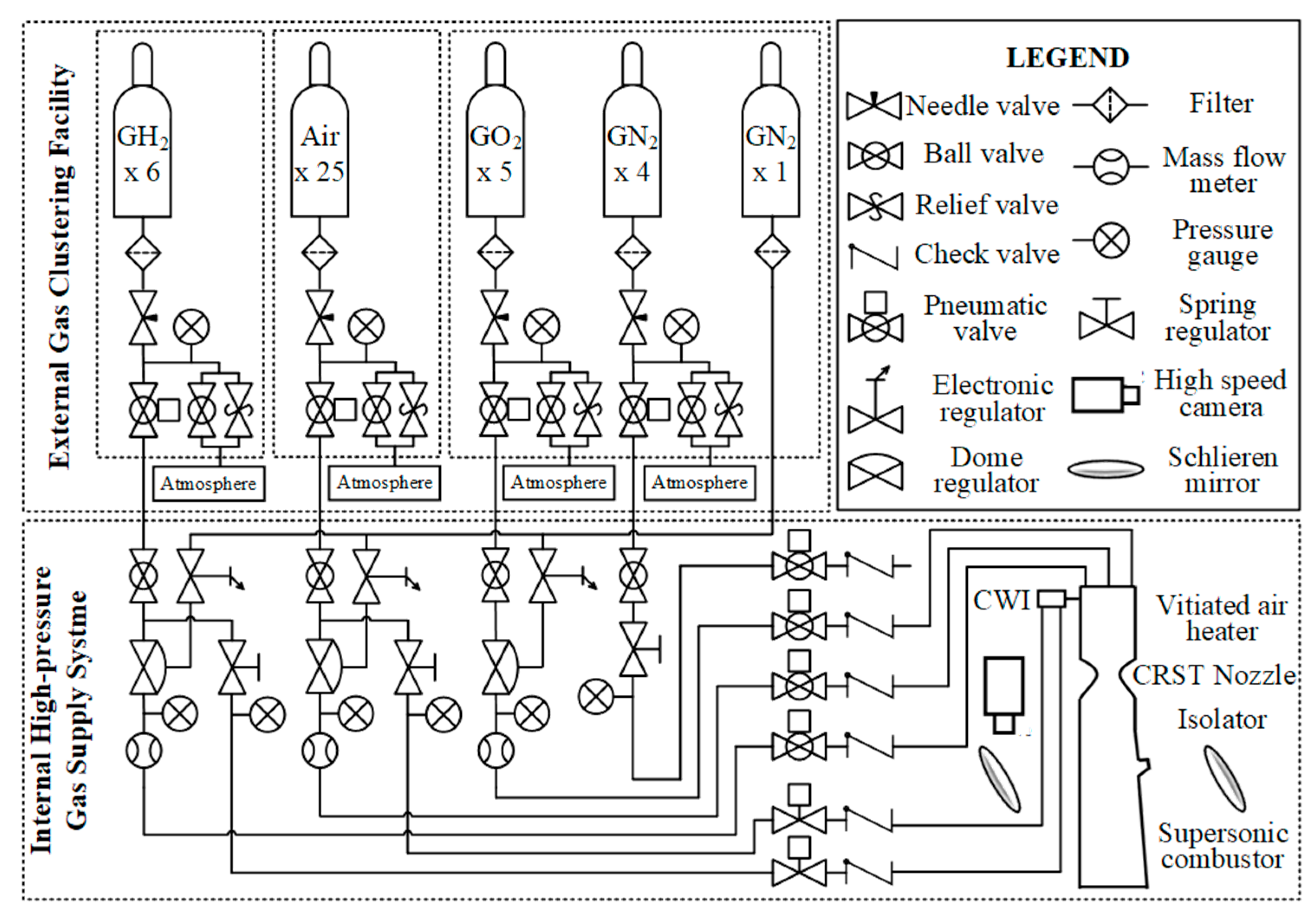
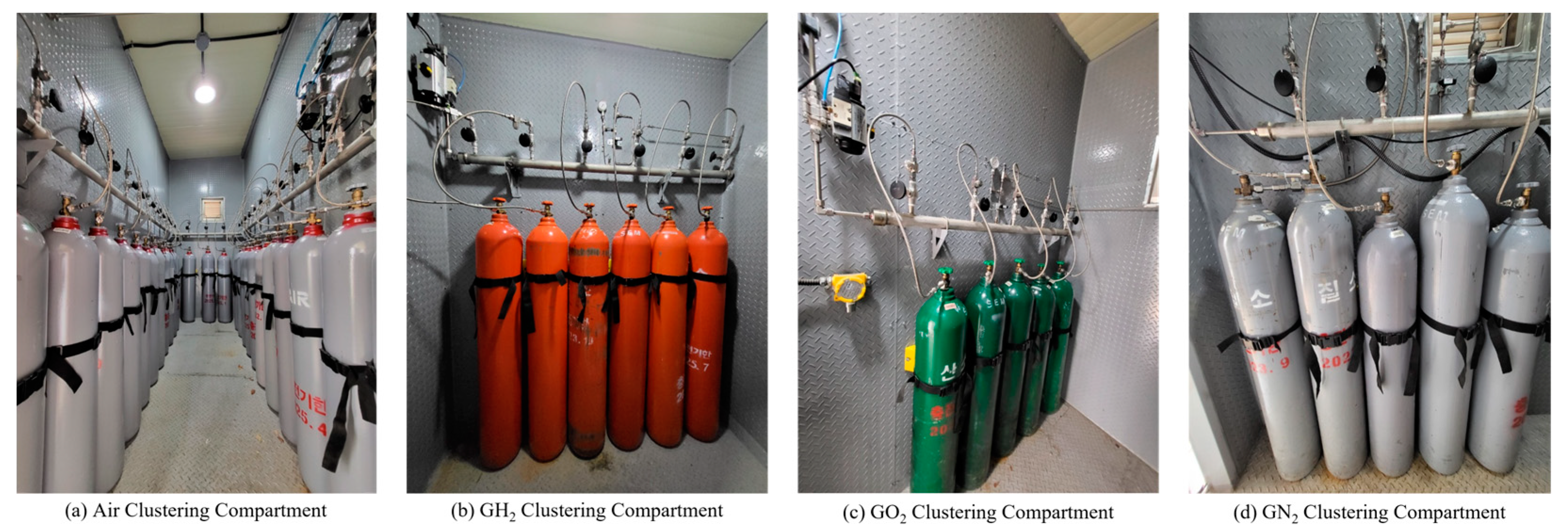
2.2. Gas Supply System
2.3. Remote Control and Monitoring System
3. Results and Discussion
3.1. Preliminary Test
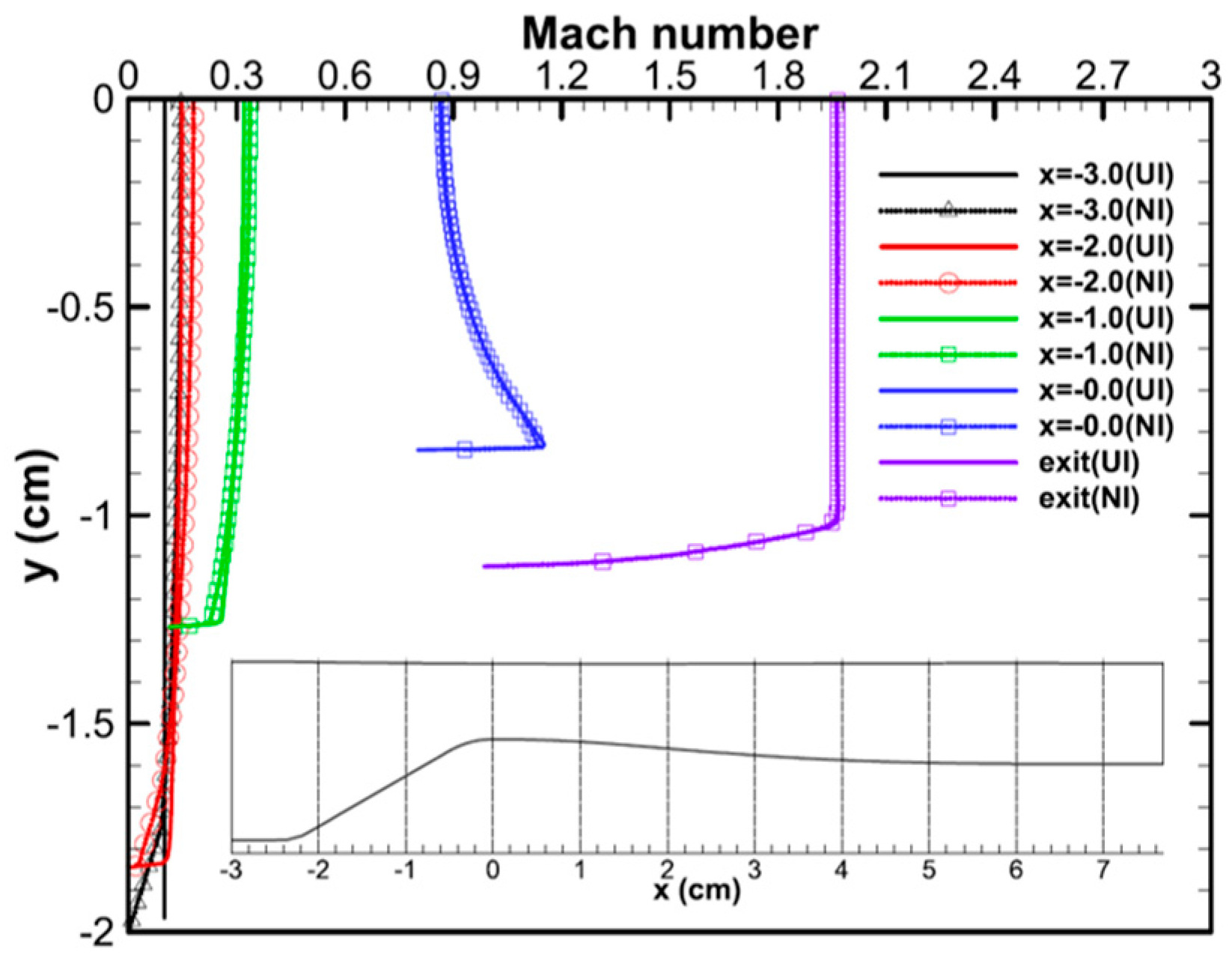
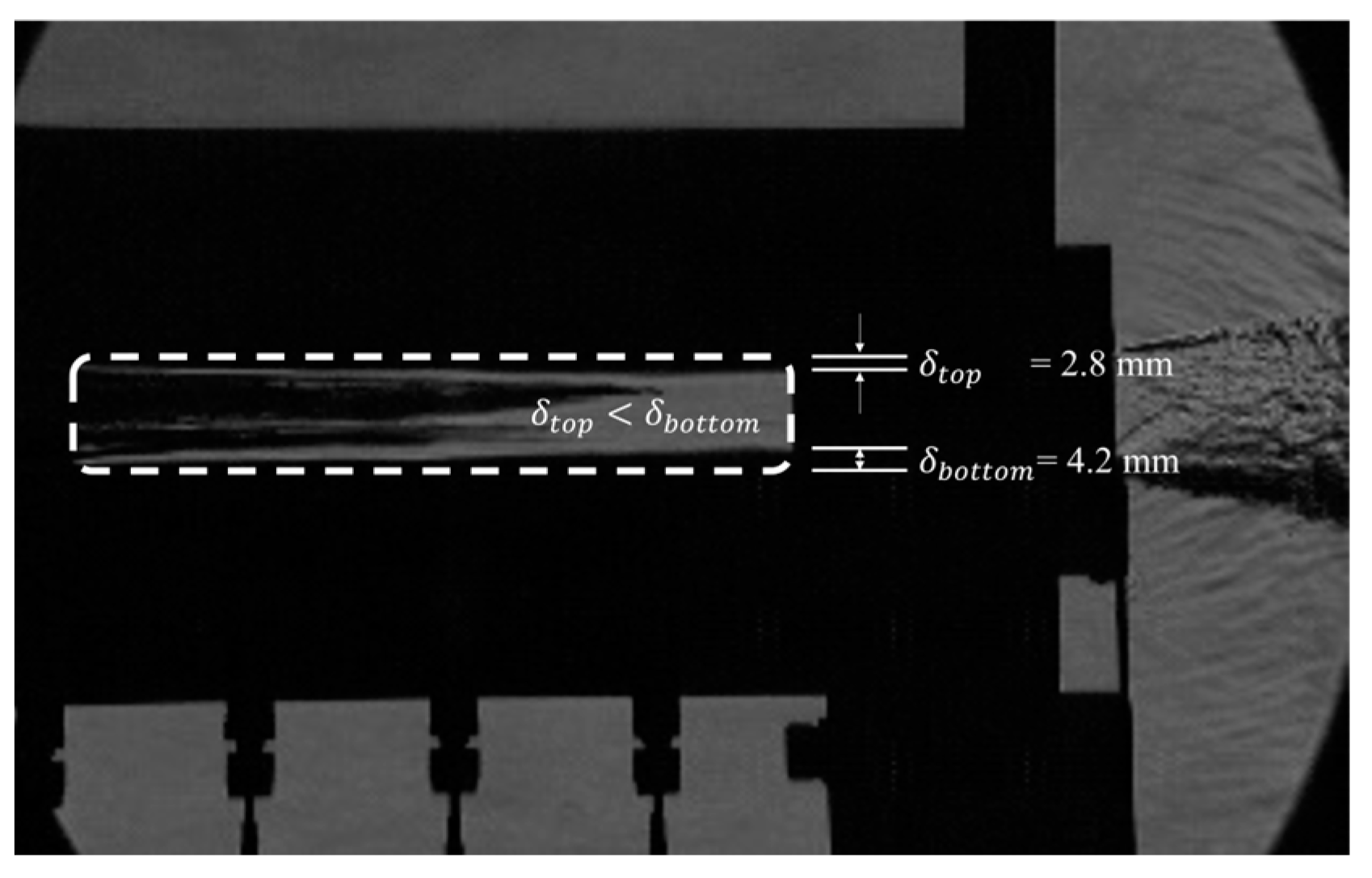
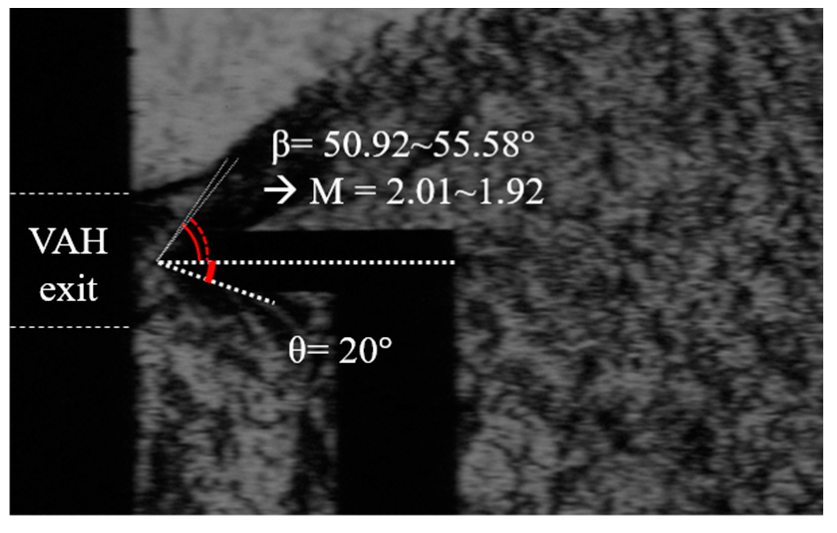
3.2. Exit Mach Number Measurement: Pc = 0.789 MPa
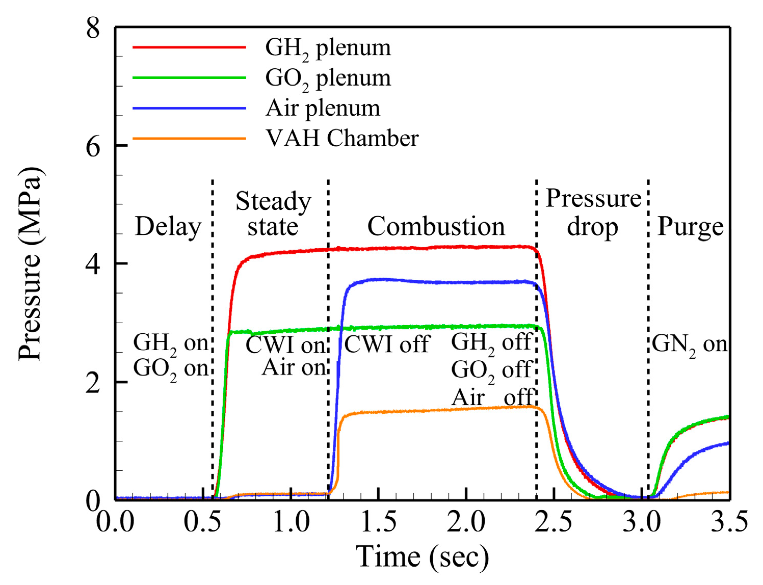
3.3. Design Verification Test Result
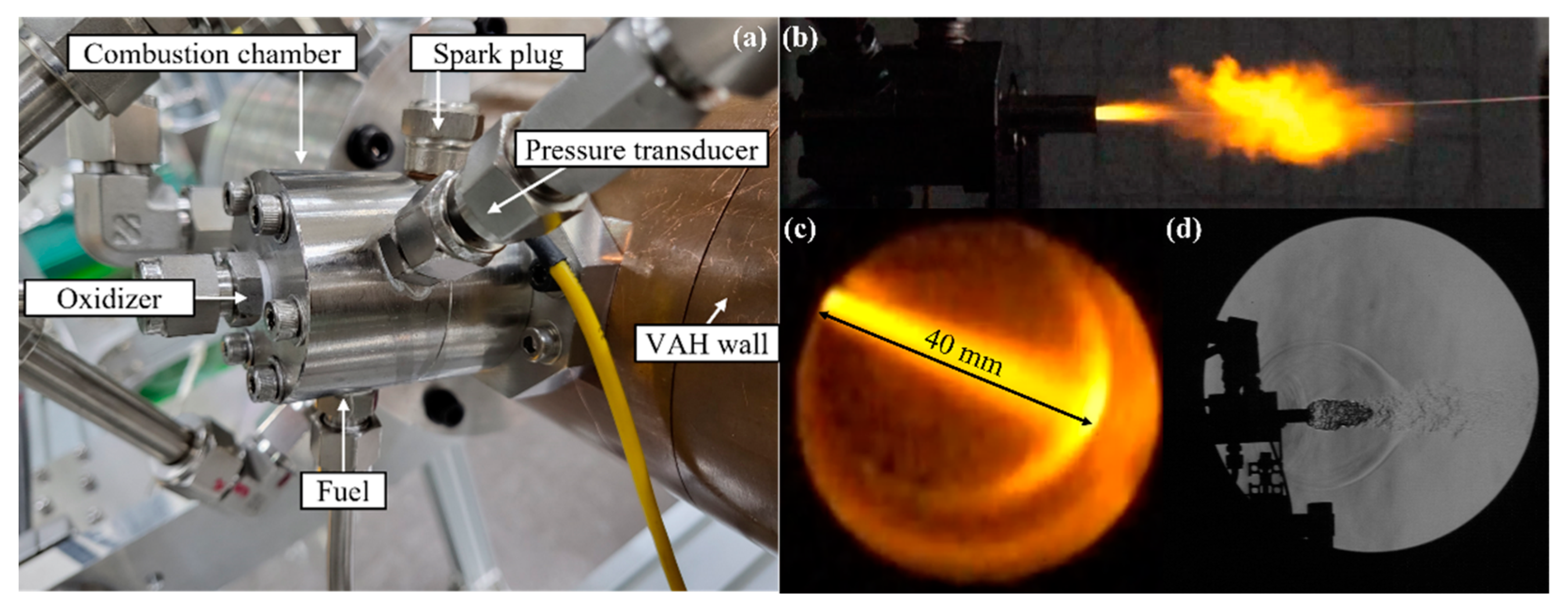
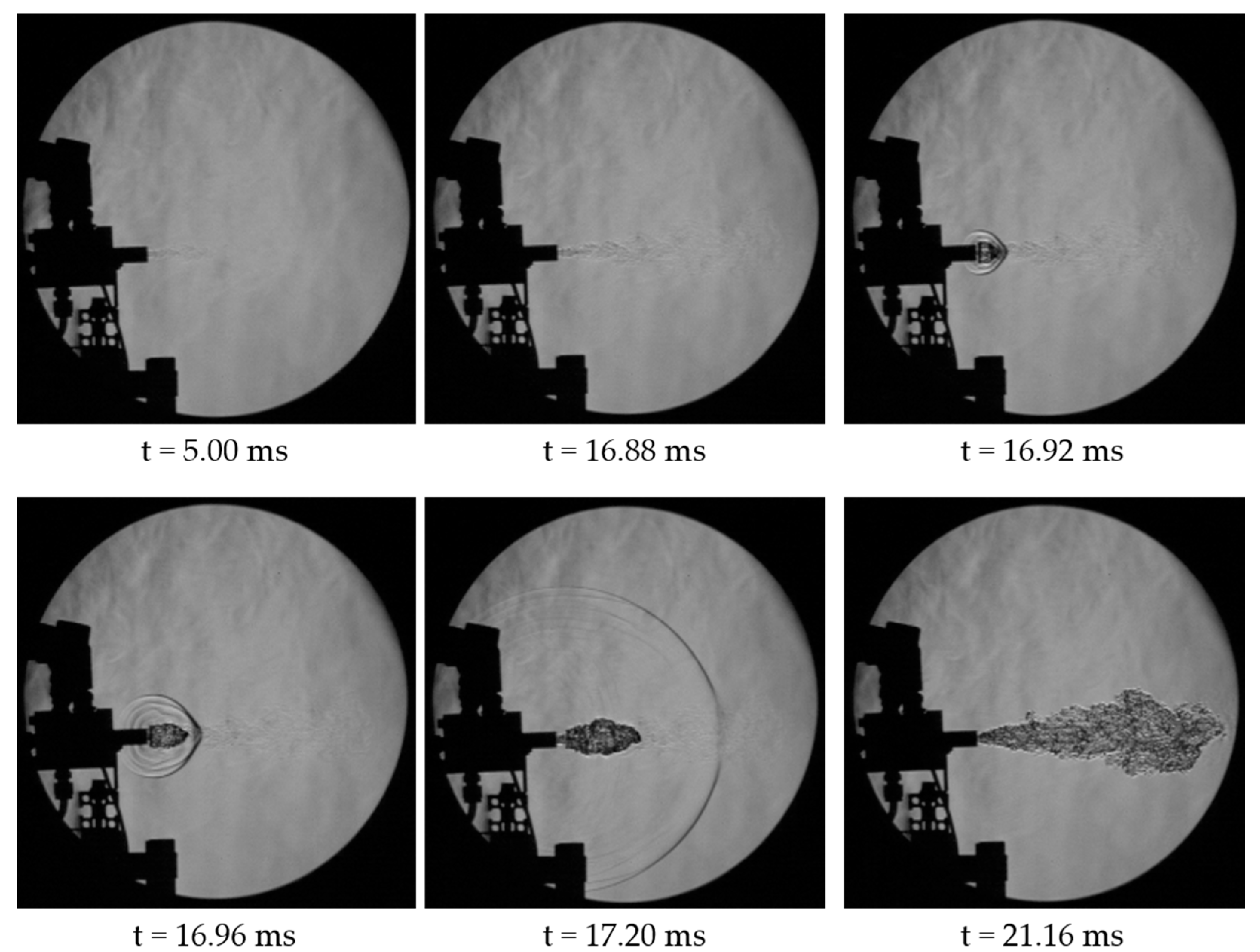
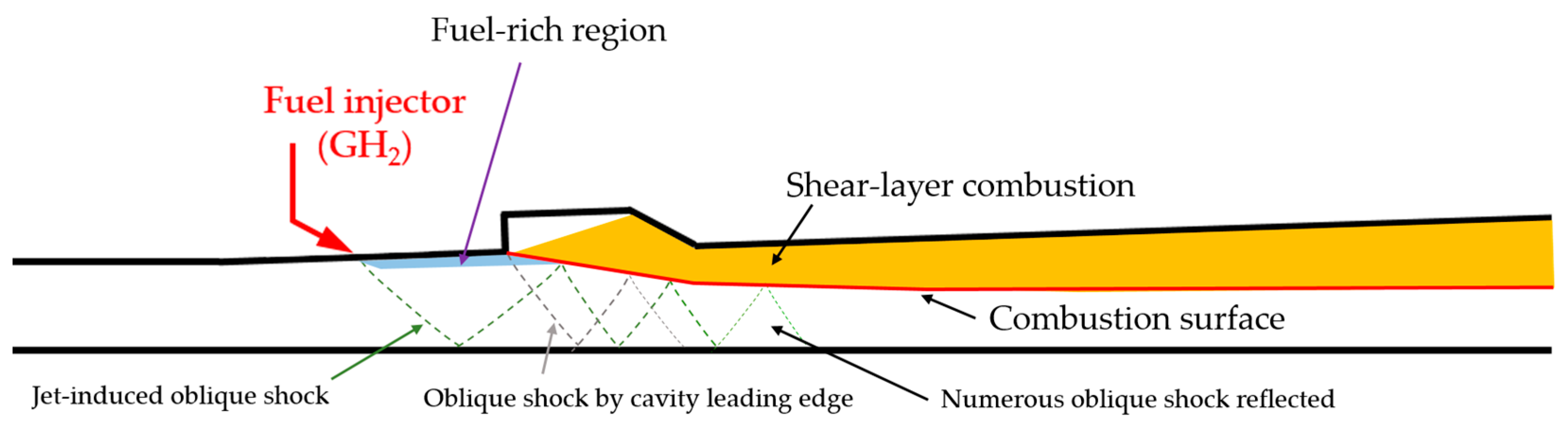
3.4. Scramjet Combustor Preliminary Test: Forced Ignition
4. Conclusions
Author Contributions
Funding
Institutional Review Board Statement
Informed Consent Statement
Data Availability Statement
Conflicts of Interest
References
- Liu, Q.; Baccarella, D.; Landsberg, W.; Veeraragavan, A.; Lee, T. Cavity Flameholding in an Optical Axisymmetric Scramjet in Mach 4.5 Flows. Proc. Combust. Inst. 2019, 37, 3733–3740. [Google Scholar] [CrossRef]
- Baccarella, D.; Lui, Q.; Lee, T.; Hammack, S.D.; Do, H. The supersonic combustion facility ACT-2. In Proceedings of the 55th AIAA Aerospace Sciences Meeting, Grapevine, TX, USA, 9–13 January 2017. [Google Scholar] [CrossRef]
- Vanyai, T.; Grieve, S.; Street, O.; Denman, Z.; Mclntyre, T.; Veeraragavan, A.; Smart, M. Fundamental scramjet combustiono experiments using hydrocarbon fuel. J. Propuls. Power 2019, 35, 953–963. [Google Scholar] [CrossRef]
- Jeong, E.; O’Byrne, S.; Jeung, I.-S.; Houwing, A.F.P. The Effect of Fuel Injection Location on Supersonic Hydrogen Combustion in a Cavity-Based Model Scramjet Combustor. Energies 2020, 13, 193. [Google Scholar] [CrossRef]
- Garrard, D.; Bates, B.; Rigney, S. Progress Report on the APTU Upgrade Activities. In Proceedings of the 24th AIAA Aerodynamic Measurement Technology and Ground Testing Conference, Portland, OR, USA, 28 June–1 July 2004; American Institute of Aeronautics and Astronautics: Reston, VA, USA, 2004. [Google Scholar]
- Meng, Y.; Gu, H.; Zhuang, J.; Sun, W.; Gao, Z.; Lian, H.; Yue, L.; Chang, X. Experimental Study of Mode Transition Characteristics of a Cavity-Based Scramjet Combustor during Acceleration. Aerosp. Sci. Technol. 2019, 93, 105316. [Google Scholar] [CrossRef]
- Zhang, J.; Chang, J.; Wang, Z.; Gao, L.; Bao, W. Flame Propagation and Flashback Characteristics in a Kerosene Fueled Supersonic Combustor Equipped with Strut/Wall Combined Fuel Injectors. Aerosp. Sci. Technol. 2019, 93, 105303. [Google Scholar] [CrossRef]
- Peng, J.; Cao, Z.; Yu, X.; Yang, S.; Yu, Y.; Ren, H.; Ma, Y.; Zhang, S.; Chen, S.; Zhao, Y. Analysis of Combustion Instability of Hydrogen Fueled Scramjet Combustor on High-Speed OH-PLIF Measurements and Dynamic Mode Decomposition. Int. J. Hydrogen Energy 2020, 45, 13108–13118. [Google Scholar] [CrossRef]
- Tian, Y.; Yang, S.; Le, J.; Su, T.; Yue, M.; Zhong, F.; Tian, X. Investigation of Combustion and Flame Stabilization Modes in a Hydrogen Fueled Scramjet Combustor. Int. J. Hydrogen Energy 2016, 41, 19218–19230. [Google Scholar] [CrossRef]
- Nishimoto, S.; Nakaya, S.; Lee, J.; Tsue, M. Effects of the Penetration Height of Ethylene Transverse Jets on Flame Stabilization Behavior in a Mach 2 Supersonic Crossflow. Proc. Combust. Inst. 2022, in press. [Google Scholar] [CrossRef]
- Wang, Z.; Sun, M.; Wang, H.; Yu, J.; Liang, J.; Zhuang, F. Mixing-Related Low Frequency Oscillation of Combustion in an Ethylene-Fueled Supersonic Combustor. Proc. Combust. Inst. 2015, 35, 2137–2144. [Google Scholar] [CrossRef]
- Yuan, Y.; Zhang, T.; Yao, W.; Fan, X.; Zhang, P. Characterization of Flame Stabilization Modes in an Ethylene-Fueled Supersonic Combustor Using Time-Resolved CH* Chemiluminescence. Proc. Combust. Inst. 2017, 36, 2919–2925. [Google Scholar] [CrossRef]
- Zhang, J.; Chang, J.; Ma, J.; Wang, Y.; Bao, W. Investigations on Flame Liftoff Characteristics in Liquid-Kerosene Fueled Supersonic Combustor Equipped with Thin Strut. Aerosp. Sci. Technol. 2019, 84, 686–697. [Google Scholar] [CrossRef]
- Li, F.; Sun, M.; Cai, Z.; Sun, Y.; Li, F.; Zhang, J.; Zhu, J. Experimental Study of Flame Stabilization in a Single-Side Expansion Scramjet Combustor with Different Cavity Length-to-Depth Ratios. Acta Astronaut. 2020, 173, 1–8. [Google Scholar] [CrossRef]
- An, B.; Sun, M.; Wang, Z.; Chen, J. Flame Stabilization Enhancement in a Strut-Based Supersonic Combustor by Shock Wave Generators. Aerosp. Sci. Technol. 2020, 104, 105942. [Google Scholar] [CrossRef]
- Nakaya, S.; Yamana, H.; Tsue, M. Experimental Investigation of Ethylene/Air Combustion Instability in a Model Scramjet Combustor Using Image-Based Methods. Proc. Combust. Inst. 2021, 38, 3869–3880. [Google Scholar] [CrossRef]
- Yang, P.; Xia, Z.; Ma, L.; Chen, B.; Feng, Y.; Zhang, J. Experimental Study on the Influence of the Injection Structure on Solid Scramjet Performance. Acta Astronaut. 2021, 188, 229–238. [Google Scholar] [CrossRef]
- Yu, K.; Su, P.; Chen, Y.; Xu, J. Inverse Design of flow Distortion Dominated by Shock Wave Interaction with Experimental Verification. Int. J. Aeronaut. Space Sci. 2021, 22, 866–873. [Google Scholar] [CrossRef]
- Gordon, S.; McBride, B.J. Computer Program for Calculation of Complex Chemical Equilibrium Compositions and Applications. Part 1: Analysis; No. NAS 1.61: 1311; NASA: Cleveland, OH, USA, 1994. [Google Scholar]
- Marshall, W.; Pal, S.; Woodward, R.; Santoro, R. Benchmark wall heat flux data for a GO2/GH2 single element combustor. In Proceedings of the 41st AIAA/ASME/SAE/ASEE Joint Propulsion Conference & Exhibit, Tuscon, AZ, USA, 10–13 July 2005. [Google Scholar] [CrossRef]
- Sung, B.-K.; Choi, J.-Y. Design of a Mach 2 Shape Transition Nozzle for Lab-Scale Direct-Connect Supersonic Combustor. Aerosp. Sci. Technol. 2021, 117, 106906. [Google Scholar] [CrossRef]
- Sung, B.-K.; Jeong, S.-M.; Choi, J.-Y. Direct-Connect Supersonic Nozzle Design Considering the Effect of Combustion. Aerosp. Sci. Technol. 2023, 133, 108094. [Google Scholar] [CrossRef]
- Han, H.-S.; Kim, J.-M.; Oh, S.; Choi, J.-Y. An Experimental Study on Characteristics of Small-scale PDE under Low-frequency Operating Conditions. J. Korean Soc. Propuls. Eng. 2018, 22, 81–89. [Google Scholar] [CrossRef]


| Facility Type | Continuous | Pulse | Blowdown | |
|---|---|---|---|---|
| Heat generation | Compressor | Pressure/ temperature rise via shock compression | Air vitiation | Combustion (combustion product) |
| Electric heating (air dissociation) | ||||
| Heat accumulation (particulates) | ||||
| Operation-time | Continuous | Order of 10 ms | Order of seconds | |
| Cost | Very high | Low | Low | |
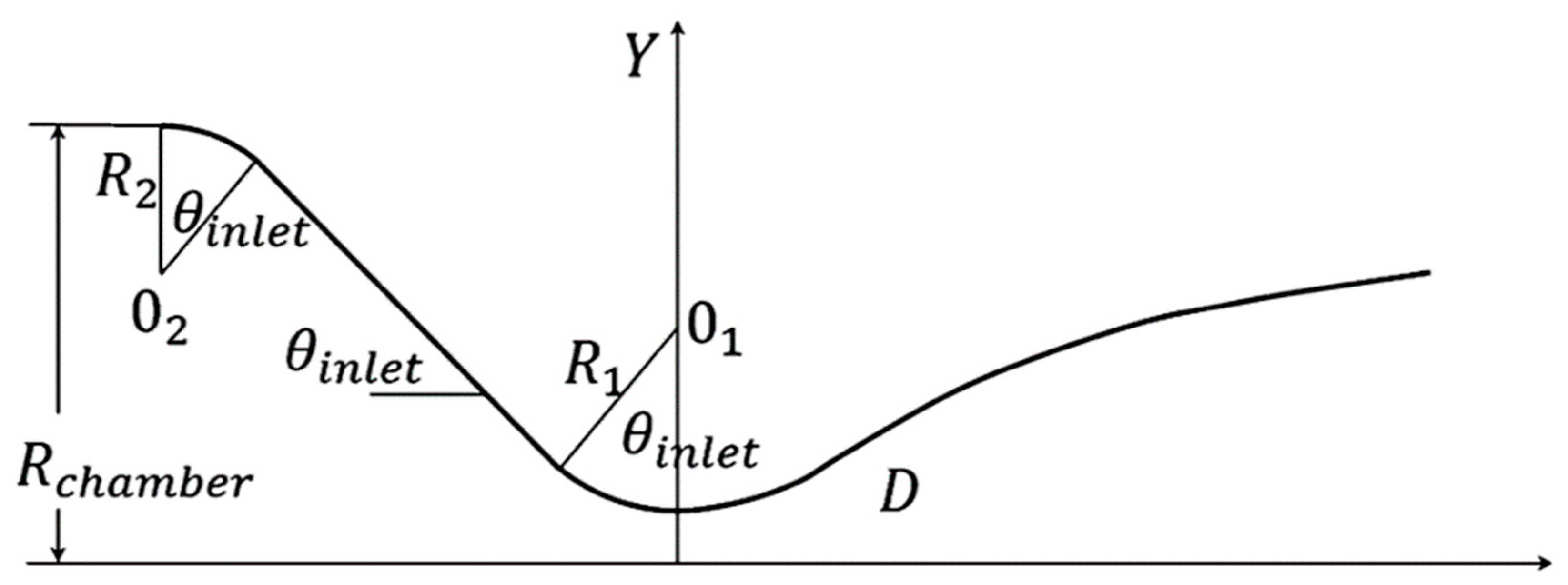
| Rchamber | R1 | R2 | Θinlet |
|---|---|---|---|
| 20.0 | 10.0 | 5.0 | 30° |
| Module | Signal Type | Control |
|---|---|---|
| NI9871 | RS485 | Mass flow meter |
| NI9205 | Voltage input | Pressure transmitter |
| NI9263 | Voltage output | Electronic regulator |
| NI9375 | Digital input/output | Solenoid valve |
| NI9212 | Thermocouple input | Thermocouple |
| NI9401 | TTL | High-speed camera, Scanivalve |
| Experiment | Theory | ||
|---|---|---|---|
| Mass Flow Rate (g/s) | GH2 | 1.72 0.61 | 2.52 |
| GO2 | 29.74 0.74 | 30.58 | |
| Air | 124.92 7.27 | 129.99 | |
| Pc (MPa) | 0.789 0.06 | 0.765 | |
| Mach | Top | 2.02 0.03 | 2 |
| Middle | 2.00 0.01 | ||
| Bottom | 2.02 0.01 | ||
| Experiment | Theory | ||
|---|---|---|---|
| Mass Flow Rate (g/s) | GH2 | 4.88 0.53 | 5.68 |
| GO2 | 68.84 0.25 | 69.04 | |
| Air | 288.39 11.38 | 293.52 | |
| Pc (MPa) | 1.685 0.07 | 1.727 | |
| Mach | Middle | 2.04 0.04 | 2 |
| Pc (MPa) | Experimental Max. Thrust (N) | Theoretical Thrust (N) |
|---|---|---|
| 1.661 | 518.30 | 515.38 |
| 1.654 | 513.31 | |
| 1.646 | 510.25 |
Disclaimer/Publisher’s Note: The statements, opinions and data contained in all publications are solely those of the individual author(s) and contributor(s) and not of MDPI and/or the editor(s). MDPI and/or the editor(s) disclaim responsibility for any injury to people or property resulting from any ideas, methods, instructions or products referred to in the content. |
© 2023 by the authors. Licensee MDPI, Basel, Switzerland. This article is an open access article distributed under the terms and conditions of the Creative Commons Attribution (CC BY) license (https://creativecommons.org/licenses/by/4.0/).
Share and Cite
Lee, J.-H.; Lee, E.-S.; Han, H.-S.; Kim, M.-S.; Choi, J.-Y. A Study on a Vitiated Air Heater for a Direct-Connect Scramjet Combustor and Preliminary Test on the Scramjet Combustor Ignition. Aerospace 2023, 10, 415. https://doi.org/10.3390/aerospace10050415
Lee J-H, Lee E-S, Han H-S, Kim M-S, Choi J-Y. A Study on a Vitiated Air Heater for a Direct-Connect Scramjet Combustor and Preliminary Test on the Scramjet Combustor Ignition. Aerospace. 2023; 10(5):415. https://doi.org/10.3390/aerospace10050415
Chicago/Turabian StyleLee, Jae-Hyuk, Eun-Sung Lee, Hyung-Seok Han, Min-Su Kim, and Jeong-Yeol Choi. 2023. "A Study on a Vitiated Air Heater for a Direct-Connect Scramjet Combustor and Preliminary Test on the Scramjet Combustor Ignition" Aerospace 10, no. 5: 415. https://doi.org/10.3390/aerospace10050415