
Review of Launch Vehicle Engine PHM Technology and Analysis Methods Research


1
Beijing Aerospace Wanyuan Science & Technology Co., Ltd., Beijing 100176, China
2
School of Integrated Circuits and Electronics, Beijing Institute of Technology, Beijing 100081, China
*
Author to whom correspondence should be addressed.
Aerospace 2023, 10(6), 517; https://doi.org/10.3390/aerospace10060517
Submission received: 29 March 2023
/
Revised: 19 May 2023
/
Accepted: 26 May 2023
/
Published: 30 May 2023
(This article belongs to the Topic Perspectives in Fault Diagnosis and Fault Tolerant Control)
Abstract
:The reliability and safety of launch vehicle launch missions might be effectively increased thanks to the fault prediction and health management (PHM) technology of engines, which could also improve with problem diagnostics and decrease the cost of operation and maintenance overhaul. This paper combines the equipment characteristics and the current state of safeguarding for large, complex space systems, introduces the intelligent launch vehicle engine PHM technology methods that are being gradually implemented in space systems, and discusses and compares fault detection and health assessment techniques. Subsequently, analysis of the measurement signals from a rocket engine was performed using an example, and it was shown that the established comprehensive health assessment structure, which is based on the fault prediction algorithm method and the fuzzy comprehensive assessment method, could successfully realize the effectiveness of the rocket engine system health assessment, which had an outstanding application value.
1. Introduction
Launch vehicle high-density launches have been commonplace in recent years, although flight mishaps, even complete flight failures, have also occasionally happened. The technical crew discovered that the flight outcomes could be greatly enhanced and the mission would be more trustworthy if the arrow had the capability to diagnose flaws and fly autonomously, that is, make the launch vehicle intelligent and smarter and make autonomous changes when faults emerge. As the brains behind clever launch vehicle propulsion, launch vehicle engines must operate with great reliability in order for space launch operations to go off without a hitch. There is no assurance that the hardware operating margin in the design and production of the engine will be sufficient as it is a highly coupled nonlinear complex system with operating circumstances that are close to the physical limits of materials [1]. The launch vehicle’s engine, however, is an incredibly sensitive and prone component of the launch vehicle system failure due to its high technical complexity and difficulty in balancing the requirements of large thrust, high specific impulse, high thrust-to-weight ratio, long operation in the harsh environment of space, and the ability to withstand significant vibration and shock loads. In order to increase the dependability and safety of next space launch missions, research into Prognostics and Health Management (PHM) technologies for the new generation of intelligent launch vehicle engine systems has become necessary [2,3,4,5,6].
In an effort to minimize the impact of engine failures, the U.S. has been trying to put engine PHM systems on launch vehicles and test stands for launch vehicle engines since the 1970s. The engine PHM system [7], which consists of hardware including sensors and operators and has a fault diagnosis algorithm at its core, could identify engine abnormalities, diagnose faults, and predict an engine’s health state. With considerable improvements in sensors [8] and their fault diagnoses [9,10], fault diagnostic algorithms, operators [4,5], and health management over the years, PHM technology for launch vehicle engines has reached its complete development, enabling quicker, more precise, and more thorough diagnosis of engine issues [11]. The health management system promptly identified engine failure in numerous Space Shuttle and Falcon-9 launch vehicle operations, allowing fault-tolerant control to successfully continue the launch mission. Hence, the likelihood of launch failure due to engine failure would be somewhat reduced by the application of defect identification algorithms for engine health management [12].
The maintenance strategy and research idea have advanced significantly in recent years due to the rapid advancement of technology. PHM technology is evolving from a conventional sensor-based diagnosis to an intelligent system-based prediction, from passive after-the-fact maintenance to precise condition-based maintenance, and from straightforward in-flight monitoring and condition monitoring of avionics equipment to thorough diagnosis and condition management encompassing all important parts of the entire aircraft system. The management system for launch vehicle engines is attempting to develop and moving toward automation, intelligence, and integration.
We contribute in the following two ways. Prior to categorizing and summarizing the PHM strategies developed for intelligent launch vehicle engines, we list each technique’s benefits and drawbacks. On the basis of examples, we also examine the research gaps in signal analysis and signal processing-based techniques for launch vehicle engine health management systems, and we provide sound ideas and recommendations for future research directions which could serve as a guide for engineering practice in this area.
2. Intelligent Launch Vehicle Engine Fault Detection
2.1. Launch Vehicle Engine Failure Analysis
There are few examples of launch vehicle failures due to the high complexity of launch vehicles and the harsh operating environment. According to past historical data, launch vehicle engines were once sensitive and prone to failures in launch vehicles, and the occurrence and development of failures were rapid and destructive [13]. It has been reported that liquid launch vehicle engine failures in the United States account for more than 60% of launch vehicle failures. European “Ariane” launch vehicles have been launched a total of 36 times, of which five launch failures were caused by engine failures. China has had 10 launch failures since 2009, 8 of which were caused by engine failures. In addition to this, engine failure will also seriously affect the safety of the engine test [14].
The main causes of liquid launch vehicle engine failures, such as propellant leakage, propulsion system component failure, excess material, and unstable combustion, are inadequate thrust and early shutdown. The Space Shuttle Main Engine (SSME), which served as a representative of liquid launch vehicle engines in the United States’ study of the failure mechanism in the late 1980s, served as the basis for a number of subsequent studies on the health monitoring of launch vehicle power systems. In order to identify the most significant failures, the U.S. collected and processed the SSME failure history data, created a failure mode and impact analysis table, and classified the failure levels in accordance with expert experience recommendations in 1987 [3]. As shown in Table 1, with a high percentage of faults occurring in high-pressure oxidant turbines and fuel turbopumps, 17 fault modes of engines like the SSME were discovered in 1990 and used as the foundation for creating a database of SSME fault modes [5,15].
2.2. Fault Detection Methods
While the measurable parameters are consistently evaluated and verified, measurable parameters relating to failure causes and failure processes need to be determined. The ultimate objective is to maximize the sensing of system operational health, to reduce unnecessary corrective maintenance, to warn of and predict approaching failures, and to foresee aberrant situations.
2.2.1. Mathematical Modeling
The fault prediction technology method based on a mathematical model is the most mature and widespread technology with the development of PHM technology, and its applications are the most extensive. The basic principle of the mathematical model for engine fault diagnosis is to consider the output of the engine mathematical model as a standard state and then determine the deviation of the actual engine operating condition from the standard state by various indicators. If the deviation is too large, the engine operating conditions in this state will be considered abnormal. This method can reflect the system’s operating condition and fault situation. At present, the application is more mature based on the static modeling of the system structure and dynamic modeling based on the object state estimation, physical parameter estimation, and time series and other signals.
The classical mathematical models are filter theory, diagnostic observer, parity equation, and parameter estimation [4]. For example, Cha J used the extended Kalman filter and the traceless Kalman filter to consider the model of launch vehicle engine [16], which combined with the redline method successfully predicted the fault at the moment of engine start, but the real-time performance was not enough. Furthermore, the ARMA model is the most classical model in the field of aerospace fault detection. In Figure 1 below [17], Xue has achieved real-time detection of launch vehicle engines based on the ARMA model, which is extremely effective for the detection of launch vehicles at steady state. The benefits of model-based engine fault detection are the ability to gain insight into the mechanics of the engine system and the ability to predict faults in real time. The higher the accuracy of modeling, the higher the accuracy of fault diagnosis. Nevertheless, the disadvantage is that it depends on modeling accuracy and hardware redundancy, and is suitable for small systems with clear input and output. For systems with unclear inputs and outputs, large changes in operating conditions and strong randomness, it is extremely difficult to establish their mathematical models and is not suitable for mathematical model-based methods. For complex systems such as launch vehicle engines, it has been challenging to establish an accurate model.
2.2.2. Signal Processing
The signal processing-based approach is to provide fault diagnosis using a certain measurement signal of the launch vehicle. When the signal processing-based method is employed for fault diagnosis, the features of the measurement signal are extracted and combined with prior knowledge to make a prediction decision based on symptom analysis. Typical signals consist of vibration, velocity, current, and magnetic flux. Certain features of the signal, such as correlation functions, higher-order statistics, spectra and autoregressive sliding average processes may be directly used for analysis, effectively avoiding the difficulty of establishing a mathematical model of the research object.
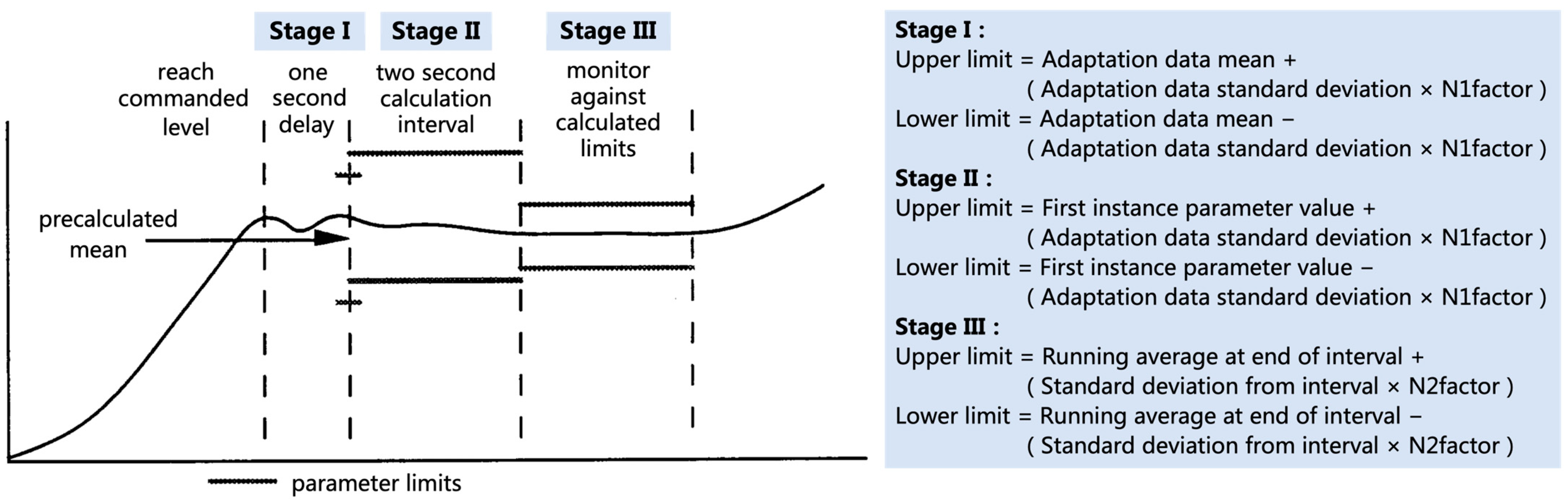
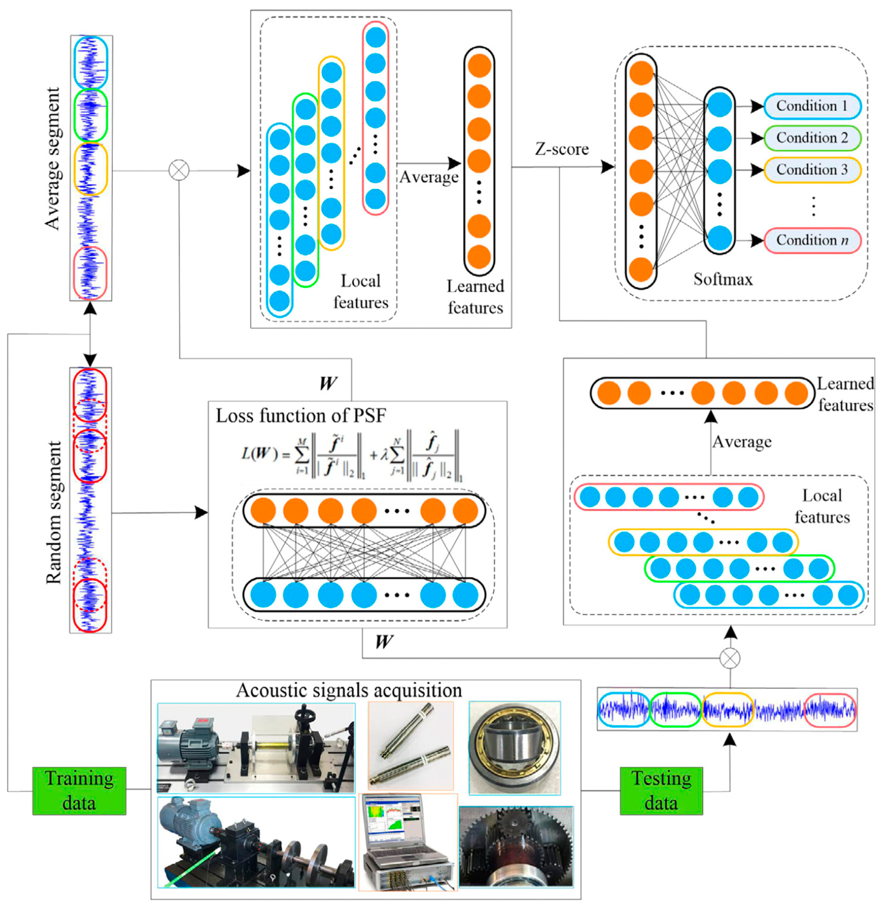
The time domain could be used as the object of signal analysis, including mean, standard deviation, phase, slope, amplitude, peak, and root mean square, or the frequency domain and spectrum. The redline system is one of the simplest and most basic signal-based fault detection methods [18]. The system for anomaly and failure detection (SAFD) proposed in the 1980s, the accelerometer safety shutdown system (FASCOS) developed in the late 20th century [19], and the turbopump vibration monitoring system [20] are all based on the redline method. The System for Anomaly and Failure Detection (SAFD) in Figure 1 is an advanced redline system developed by Rock Dain for SSME real-time anomaly detection, which could provide real-time monitoring of 22 engine measurement parameters in the steady-state segment of SSME. The algorithm uses a statistical approach for generating limits for the parameters based on mean and standard deviation. It calculates a running average of the last five samples for each parameter and compares this running average to the limits. If three of these parameters exceed the threshold at the same time, the engine is determined to be operating abnormally [18]. The adaptation data refer to the result of the adjustment calculation, which needs to be prepared before the test run, and is used for the generation of the initial detection threshold in the steady state period. Running Average refers to the average value of sensor measurement values at five moments before the current moment. On the basis of the SAFD algorithm, the researchers added the training of N1factor and N2factor to realize the abnormal detection of the engine steady state [21]. Nevertheless, since the shortcomings of the redline system with high misdiagnosis and leakage rate, more methods have been gradually developed, including the Adaptive Threshold Algorithm (ATA) for measuring steady-state processes, Adaptive Correlation Algorithm (ACA), Adaptive Weighted Sum Square Algorithm (AWSSA), Envelop Algorithm (EA) for measuring transient processes, and Adaptive Correlative Safety Band (ACSB). In this regard, the Short Time Fourier Transform (STFT), Wavelet Transform (WT) [22], Hilbert–Huang Transform (HHT) and Wigner–Ville Distribution (WVD) are the most popular time–frequency methods. In recent years, new data processing methods have emerged, which typically include Principal Component Analysis (PCA) [23], Independent Component Analysis (ICA), and so on [24]. Ji investigates the feature normalization process in sparse filtering and introduces an intelligent fault diagnosis method for acoustic signal processing based on parallel sparse filtering [25], which effectively achieves high diagnostic accuracy for mechanical fault classification. The flow chart of the proposed method is displayed in Figure 2. The signal processing-based method is independent of any model and is much faster, but the detection accuracy of the method is highly dependent on the statistical accuracy of the data and is not suitable for handling smooth signals, which can easily lead to false alarms.
Figure 1.
System for Anomaly and Failure Detection [21].
Figure 1.
System for Anomaly and Failure Detection [21].

2.2.3. Knowledge Learning
For a launch vehicle engine, which is an extremely complex system with no apparent system model or signal symptoms, a progressive learning mechanism is necessary to automate the fault detection. When analysis is performed based on knowledge, the input and output are compared and classified in a consistent manner, while machine learning (ML) is used for training and learning to convert large amounts of data into knowledge for making fault diagnosis and decisions. The characteristic that can be learned intelligently from a large amount of data is what distinguishes knowledge-based fault detection from signal-based and model-based [26], and for this reason, knowledge-based methods are also referred to as data-driven fault diagnosis and prediction. Generally, knowledge-based fault detection can be divided into qualitative and quantitative methods.
Qualitative methods involve Fault Trees (FT), Signed Directed Graph (SDG), and Expert Systems (ES) [27]. One of the most typical approaches is the ES-based approach. An expert system is a rule-based system that embodies human expertise and was initially developed in the 1980s [28]. Because of its ability to reason under uncertainty, expert system-based fault detection received a lot of attention in the 1990s. Nevertheless, it also has weaknesses such as a more restrictive system nature and poor generality. In addition, by combining production rules and minimal reduction of fault trees, the failure modes of the system could be effectively extracted, and an optimized inference engine is constructed based on the failure modes for logical reasoning using forward inference patterns [29].
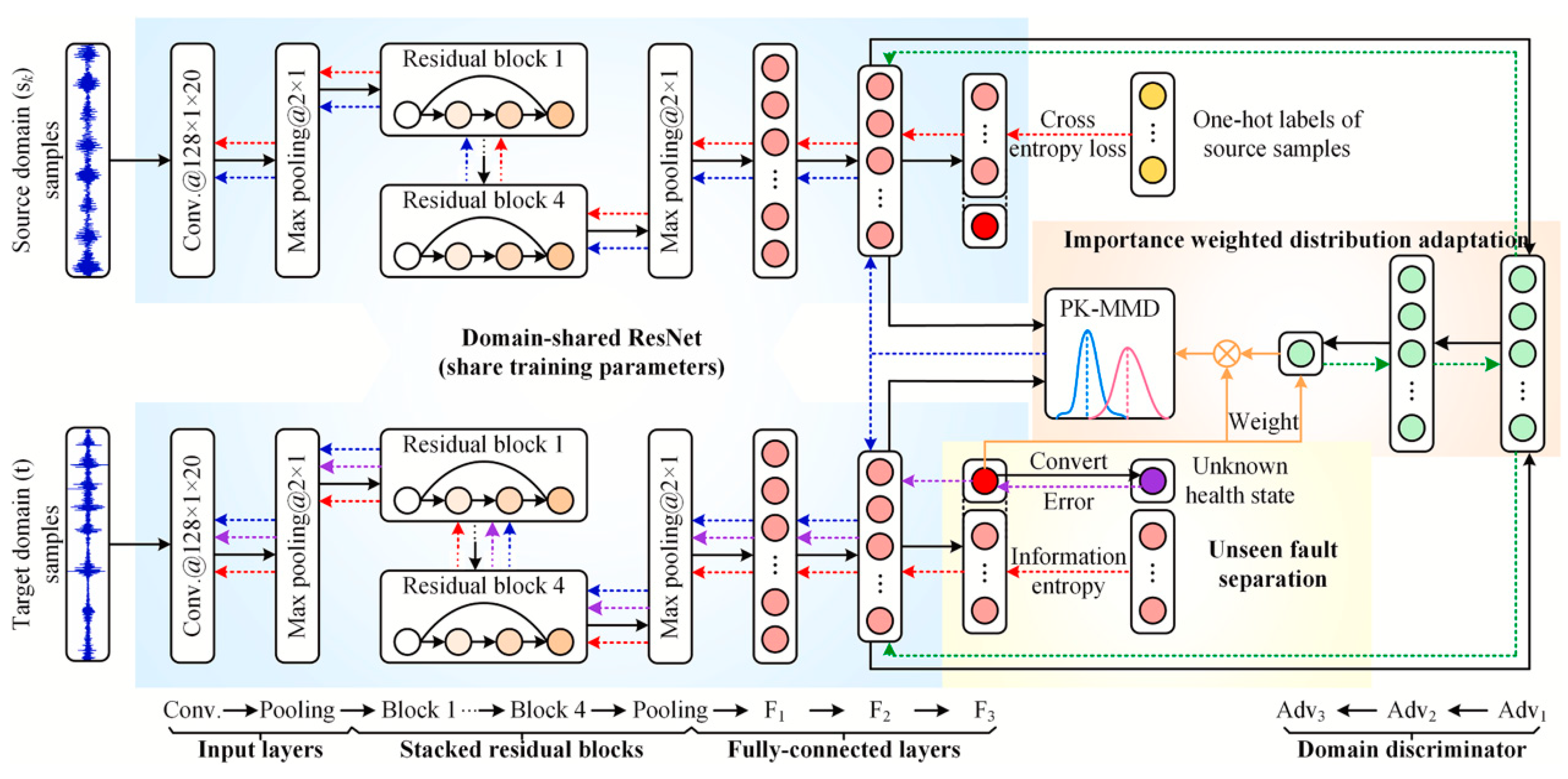
Quantitative knowledge-based fault detection methods include statistical prediction techniques such as the Principal Component Analysis (PCA), Partial Least Squares (PLS), Bayesian Classifier and the currently popular Support Vector Machine (SVM) analysis method [30]. In this regard, SVM applied to fault detection has the superiority of being able to overcome the situation of small samples and limited features and provide maximum analysis and prediction of the data [31]. Non-statistical analysis methods such as Neural Networks (NN) and Fuzzy Logic (FL) are also included in quantitative knowledge fault detection. With the powerful ability in nonlinearity and adaptive learning capability, Neural Networks-based fault detection is widely used and has turned out to be one of the most mature non-statistical fault diagnosis tools [32,33]. The Neural Network-based fault prediction method is trained to learn based on the historical data provided, and then the constructed network structure is constructed to achieve the required accuracy for prediction, which is appropriate for the intelligent prediction of complex systems. As the launch vehicle engine system has nonlinear and complex features, it will become an essential tool for its diagnosis. Zhao introduced a new semi-supervised GNN approach that utilizes a combination of tagged and untagged information for device fault diagnosis [34]. Additionally, this paper proposed two cross-domain aero engine fault diagnosis methods, one-stage-transfer-learning ELM (OSTL-ELM) and two-stage-transfer-learning ELM (TSTL-ELM) [35], which had a fast training speed and a good real-time diagnosis. As shown in Figure 3, Yang [36] proposed a framework called multi-source transfer learning network (MSTLN) to aggregate and transfer diagnostic knowledge from multiple source machines by combining multiple distributed adaptive subnetworks and multi-source diagnostic knowledge fusion modules. This approach could reduce the misdiagnosis rate and obtain improved transfer performance for unbalanced target samples. Additionally, to diagnose multiple fault types at the same time, an ensemble model based on multiple machine learning methods was established [37].
In addition, Neural Network-based fault detection also suffers from “black box” characteristics that are not reasonably interpretable, long machine learning time, large computational power requirements, and the need for a larger number of labeled sample data. Fuzzy Logic (FL) is a method of dividing feature spaces into fuzzy sets and reasoning by using fuzzy rules that essentially provide approximate human reasoning. Zheng [38] and Lyu [39] thoroughly investigate the robust stability as well as the reliable control problems of several types of fuzzy systems for T–S fuzzy systems. Simultaneously, fuzzy clustering contributes to fuzzy modeling. Huang [40] investigated a new fault diagnosis method based on fuzzy clustering for fast knowledge modeling. Palade [41] combined fuzzy clustering with fault diagnosis models for coarse data modeling. Fuzzy prediction possesses advantages in dealing with complex systems such as uncertainty, nonlinearity, and having linguistic features to describe human knowledge, but it also has fault detection which is devoid of temporal parameters and lacks time control.
2.2.4. Digital Twin
Recently, the development of digital twin has shown an explosive trend, which has been widely used in satellite communication, smart city construction, aircrafts, vehicles, ships, and other fields [42]. Undoubtedly, there is also a very broad development prospect in the field of aerospace. NASA proposed as early as 2010 that it would successfully apply digital twin to simulation-based systems engineering in 2027 as one of NASA’s top technologies for the next three decades [43].
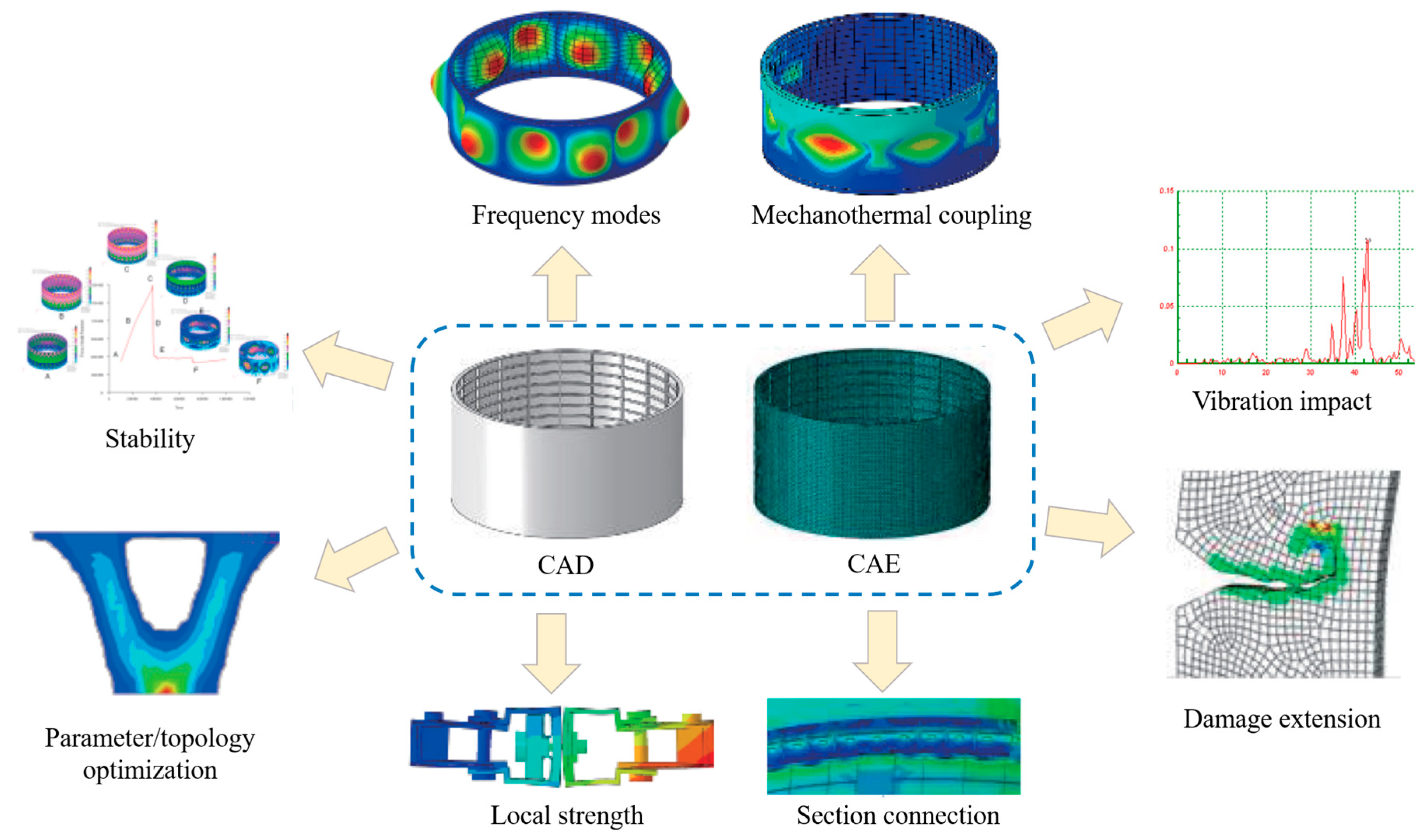
The digital twin-based PHM approach refers to the combination of the original PHM technology with digital twin technology [44]. On the basis of building a digital twin, physical and virtual devices are interactively fused using the twin data to drive the fusion of physical and virtual devices, giving full play to the role of simulation data and virtual models, in order to achieve early prediction and accurate positioning of faults. To begin with, the physical information system achieves data acquisition and transmission to the virtual model through sensors and communication networks. The virtual model, driven by twin data, achieves synchronous simulation operation with the physical entity and simulates possible faults to achieve fault location. Meanwhile, a repair solution is obtained with the aid of a historical fault library. Eventually, the solution is run on the virtual model and the physical entity successively to verify the feasibility of the solution. Currently, there are a few case studies for launch vehicle engines, but with the progress of sensing technology, digital twin-based fault detection has been gradually applied to launch vehicle structure manufacturing [45], test launch [46], and other fields, which provide theoretical reference for intelligent fault diagnosis of engines based on digital twin. The following Figure 4 shows the schematic diagram of a digital twin-based structure design technology. Tao Fei established a five-dimensional digital twin model of complex equipment, and proposed that PHM supported by digital twin will bring a dynamic physical and virtual equipment real-time interaction of fault observation mode, a fault analysis mode, a maintenance decision mode and an autonomous precise service of PHM function execution mode [47].
2.2.5. Hybrid Fault Detection
Mathematical model-based, signal processing-based, and knowledge-learning-based fault detection methods each have their own advantages and limitations of applicability. Mathematical model-based approaches could use a small amount of data but require a clearly visible model that can represent the inputs and outputs. Signal processing-based is without a model, but it requires a certain feature for fault diagnosis, and its diagnostic performance decreases when the input is unknown. Knowledge-based fault diagnosis has the advantage for complex and huge system analysis, but it relies on a high amount of historical data and a lot of learning training, and it requires high computational power. On the one hand, in order to give full play to the advantages of each diagnostic method, they are often mixed together, which is called a hybrid fault diagnosis method. On the other hand, in the design of complex PHM systems for intelligent launch vehicle engines, fault diagnosis algorithms are often determined based on system design objectives, such as time sensitivity, detection accuracy, coverage of faults, coverage of operating conditions, etc. If there are too many system design objectives, a single algorithm is often difficult to meet the requirements, and it is also necessary to integrate multiple methods to complete the diagnosis and prediction of faults in parallel [48,49,50]. For instance, Brotherton T has developed techniques that couple neural nets with automated rule extractors to form systems that have good statistical performance, easy system explanation and validation, potential new data insights and new rule discovery, novelty detection, and real-time performance [51]. Additionally, they apply these techniques to data sets collected from operating engines. Sergei Nikolaev proposed a methodology for building hybrid models of gas turbine power plants for solving the task of prescriptive and predictive plant health analytics [52].
3. Intelligent Launch Vehicle Engine Health Management
3.1. Health Assessment
Health assessment is considered as one of the crucial PHM techniques to evaluate the current health of the system or the health of its critical components [53]. The health assessment of launch vehicle engines is to evaluate the health degradation of the engine based on the monitoring information, providing fault diagnosis conclusions with confidence levels. By combining the health history, operating status, and operational load characteristics of the system, an evaluation model reflecting the current performance is established to accurately grasp the operating status of the launch vehicle engine, so that various performance degradation processes of the system or its key components may be discovered in a timely manner [54,55]. Furthermore, the health assessment of the launch vehicle motor helps to provide a reference for the maintenance personnel to make maintenance decisions, improve maintenance efficiency, and increase the efficiency of mobilizing components or maintenance resources.
The foundation of the launch vehicle engine health assessment is condition monitoring data, so the primary issue of health assessment is how to effectively select the characteristic parameters that could indicate the engine operation for condition monitoring [56]. Theoretically, more information provides a more comprehensive and accurate reflection of the system’s operating status, and can effectively carry out the subsequent fault isolation and fault location work. However, too many measurement points can easily introduce sensor measurement errors, while a cascading system will gradually superimpose the errors of each node, affecting the final assessment accuracy. Therefore, in order to fully reflect the operating status of launch vehicle engines, it is necessary to select parameter sets that are suitable for measurement and recording to maximize the information of the measured data and reduce the redundant information of the characteristic parameter sets. To follow the above principles, the selection of feature parameters includes the following two ideas. The first one is to convert the selection of test points into an objective optimization problem with constraints from the testability point of view [57,58,59], using algorithms such as greedy algorithms, or heuristic search algorithms, such as particle swarm algorithms and ant colony algorithms to find the best. Afterwards, the information collected from the optimized test points is used to form the final set of feature parameters. The second type is to select some of the main features from the existing feature parameter set from the feature selection perspective [60,61,62], which usually uses algorithms, such as Principal Component Analysis, popular learning algorithms, or compressed self-coding to determine the final set of feature parameters. After the feature parameter set is determined, a health index could be constructed based on the feature parameter set to visually represent the performance state of the system. The health index is generally normalized to the interval 0–1, which could be analyzed qualitatively or quantitatively to determine the health status of the system.
3.1.1. Quantitative Methods
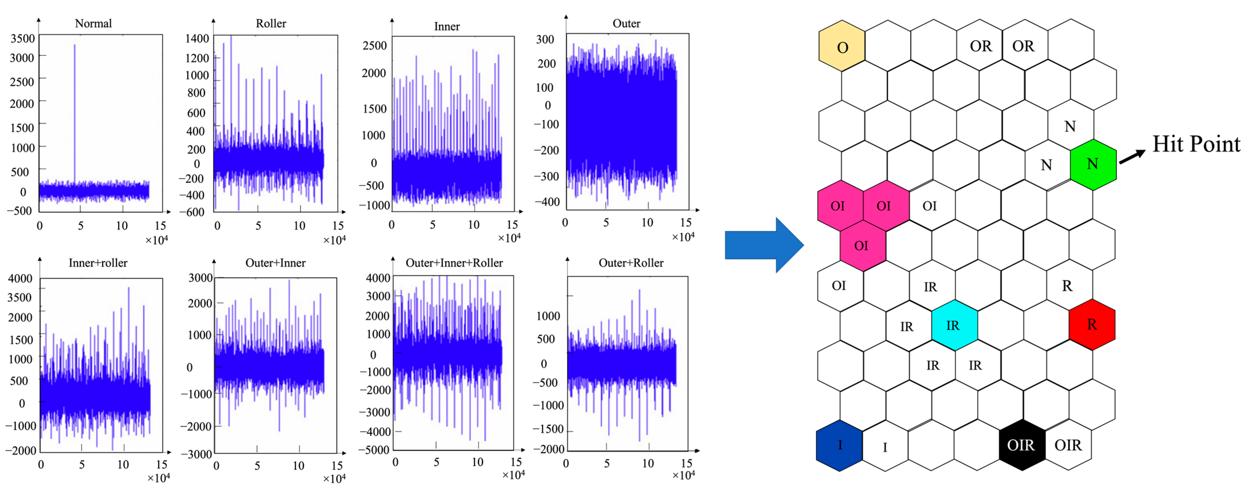
From the quantitative point of view, the change process of the health index reflects the performance degradation course of the launch vehicle engine. Therefore, the performance change trend could be predicted by algorithms or models. For instance, Liao introduced a method [63] for the bearing health assessment by applying the fast Fourier transform (FFT) to extract the vibration signal as a feature vector representing the health status of the bearing. The feature vectors are then transformed using a Neural Network technique, self-organizing mapping (SOM), to derive health maps for different bearing failure modes, and the evaluation model is shown in Figure 5. The left image shows a plot of the vibration data acquired while the machine is operating in a normal condition, as well as plots of seven different combinations of the failure modes identified. The right map shows eight areas which are labeled by ‘N’, ‘RF’, ‘IF’, ‘OF’, ‘OR’, ‘OI’, ‘IR’, and ‘OIR’, indicating the normal status, roller defect, inner-race defect, outer-race defect, outer-race and roller defect, outer-race and inner-race defect, inner-race and roller-defect, and outer-race and inner-race and roller defect, respectively. The input vector of a specific bearing defect was represented by the Best Matching Unit (BMU) on the map indicated by a “Hit Point”. By looking at the area pointed by the “Hit Point”, the failure mode of the bearing was determined [64]. Yang Feng [65] introduced a dynamic smoothing algorithm to predict the health state of a system by using a health index. Hamed Zeinoddini Meyman [66] proposed a strategy of using technology class parameters together as feature parameters, and then, using an artificial Neural Network algorithm to construct a health index to monitor the health state of the system throughout its life cycle by solving the health index. Professor Michael Pecht [67] of the University of Maryland selected the set of feature parameters to construct the circuit health index from a fault diagnosis perspective, and used the features extracted from the circuit response to reflect the performance state of the key components of the circuit, and analyzed the circuit health state with improved particle filtering algorithm to evaluate and predict the circuit health state in an adaptive manner. Liu Kaibo [68] from Georgia Institute of Technology proposed a method to integrate feature parameters collected by multiple sensors to construct a health index to characterize system performance. Furthermore, the process from feature parameter selection, feature preprocessing, feature fusion to health index construction was discussed in detail. Taking an engine system as an example, it was verified that the health index model based on multi-sensor data fusion could more accurately characterize the system performance degradation history. Liang Zhou combined simulation techniques with deep learning methods to construct a deep digital twin model which could intuitively reflect the engine health condition in real-time [69].
3.1.2. Qualitative Methods
From the qualitative point of view, the health index could be divided into different health levels, each of which represents a performance state of the system. Maintenance personnel are able to make maintenance decisions corresponding to the different health levels. Professor Michael Pecht [70] proposes to construct a health index for each key sub-circuit utilizing the system circuit characteristics to address the performance degradation of electronic systems. The multiple subhealth indices then synthesized into an overall health index. Through classifying the health index into different levels to evaluate the current performance state of the system circuit, it could be possible to evaluate the current performance state of the electronic system through the constructed health index by monitoring only a few key nodes in the circuit. Maryam Khoddam et al. [71] used scoring and weighting to construct a health index of the system and classified the health index into three levels of health, performance degradation, and risk to characterize the performance status of high-voltage circuit breakers. Prasanna Tamilselvan [72] addressed the problem of multi-sensor data fusion and feature extraction using deep belief networks, starting from the trouble-shooting problem of complex systems, such as engine systems and power transformers. They used BP Neural Network to fuse the extracted features into health indices, and then classified the health indices into different health classes to further investigate the fault states of the systems. Lu Chen [73] worked on the health status problem of engine rolling bearings, and the method flow is shown in Figure 6. In the first place, the collected rolling bearing data from intact to faulty are distributed into different health classes, and then the convolutional Neural Network is used to extract features from the bearing data. The extracted features are classified into the corresponding health classes according to the classifier, which could complete the fault state diagnosis of rolling bearings in engines.
As a summary, for intelligent launch vehicle engine systems with high complexity and integration, monitoring all components or functions of the system one by one leads to serious waste of resources and the burden of cost. Comparatively, building an overall system health state model with the method based on feature parameter fusion provides an effective description of the performance degradation history of the engine, and such an approach has a high assessment accuracy, which can improve the safety and maintenance efficiency of the system [72,74,75].
3.2. Health Management
The health management system [76] is to collect data through sensor integration, obtain relevant characteristic quantity information with the support of data mining methods such as the Fourier transform and classification clustering, constantly monitor the internal state and external environment, and perform timely fault diagnosis and prediction to guarantee system reliability and safety and maximize economic benefits. The Open Systems Architecture for Condition-Based Maintenance (OSA-CBM) [77], which was led by Boeing and developed through multiple organizations from industry, military, commercial manufacturing, sensor technology, and other fields, was a typical hierarchical converged PHM architecture. Its framework architecture diagram is shown in Figure 7. Presently numerous equipment health management systems were designed and implemented with this model as their architecture. The OSA-CBM-based equipment health management system not only focused on equipment condition monitoring and maintenance, but also emphasized intelligent and information-based equipment management, which is a strong guideline for the design of an engine system health management system for intelligent launch vehicles.
3.2.1. Design Requirements
The principal purpose of the health management system on launch vehicle engines [1] are as follows. On the one hand, it could improve engine safety by providing early real-time monitoring of operating conditions which might develop into critical system failures. On the other hand, it may minimize failure isolation time for failed components to become linearly replaceable units through the automatic reasoning of the data to assist in reducing maintenance assurance costs and termination tasks. The autonomous logistics approach introduced in the Joint Strike Fighter is an example of the application of airborne diagnostics and predictive health management capabilities [78]. The aim is to abandon timed engine inspections and instead rely on situational health assessments.
The function of the health management system on a launch vehicle engine is to acquire data, monitor and evaluate the current engine condition, and to forecast the in-future condition of the engine. Subtle changes in a few combinations of measured parameters may predict the early symptoms of a failure process. These changes in parameter characteristics are often hard to detect by simply observing whether the parameter values are out of bounds, since the parameter values usually remain within the normal range. The analysis of trends in parameter values over time under a particular operating condition has the capability to help detect shifts in data, anomalies in the rate of change of data, and anomalous distributions of data. The operation of the fuel and lubrication systems, as well as the rotational functions, can all be measured in order to examine these trends.
3.2.2. Operation Process
The health management system of intelligent launch vehicle engines includes a large number of different devices and components. Health status management of such a complex system requires the completion of multi-level health information collection of components, equipment, subsystems, and systems. Additionally, the collected information is used to realize health management applications such as system-wide condition monitoring, fault diagnosis, health status assessment, and maintenance-assisted decision-making. The business process of an intelligent launch vehicle engine health management system is shown in Figure 8 [79], which mainly covers system health information collection, a health management database, and health management application. The data and knowledge support for health management business, such as fault diagnosis and health status assessment are based on the system’s multi-level health information collection and health business knowledge, which in turn provides operation and maintenance guarantee services for launch vehicle motor system equipment.
4. A Multilayered and Multifactorial Health Assessment Method for Launch Vehicle Engine under Vibration Conditions
4.1. Instance Overview
During launch vehicle flight, vibration signals cover low, medium, and high frequencies, which seriously affect the normal operation of equipment structures and electrical systems of several launch vehicle systems, resulting in a decrease in the reliability and safety of the rocket. Mechanical vibrations could provide high information content and are very sensitive to mechanical hardware failures and the external environment. Traditional launch vehicle health management is stratified and analyzed from the hardware perspective, but it could hardly monitor all internal components and there are missed alarms. This part performed an example analysis of launch vehicle engine measurement signals based on vibration signals and establishes a comprehensive health assessment structure based on a fault prediction algorithm and a fuzzy integrated assessment method. In this way, the engine health level could be evaluated and the internal health of the engine could be analyzed more comprehensively. The work and conclusions of this chapter were obtained by the authors through experiments.
4.2. Instance Scheme
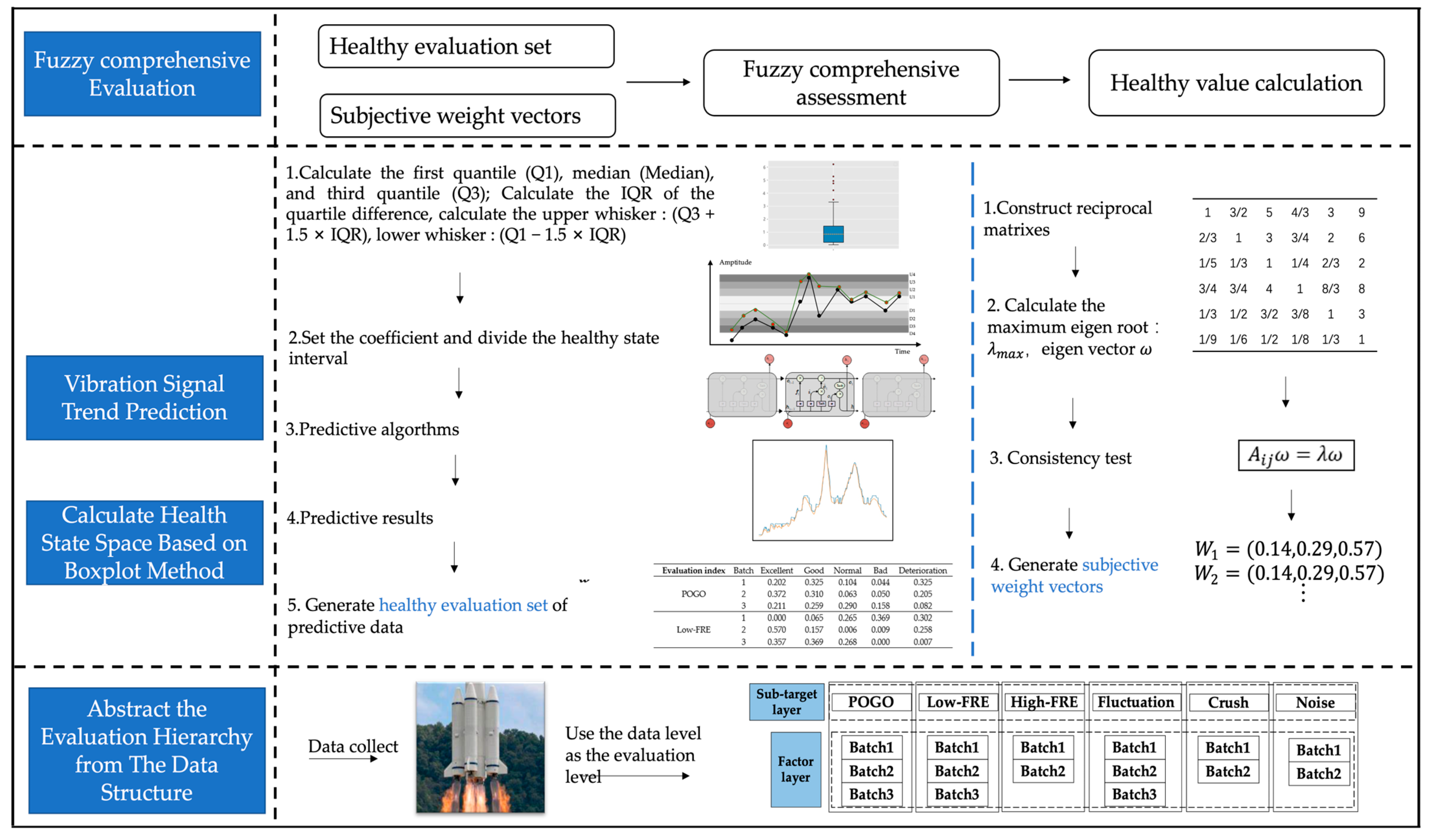
The instance scheme of the vibration signal-based evaluation method is shown in Figure 9.
Firstly, through the state space partitioning method based on the box-line diagram, we are able to obtain the upper and lower limit values of the state waveform. Secondly, the predicted waveform is obtained by the prediction algorithm LSTM and compared with the state space of health values to determine the probability of evaluation distribution, which is set as the evaluation set. After that, the weight relationship between each layer of data on health effects is calculated by the hierarchical analysis method (AHP) and set as the weight set. Finally, the evaluation set and the weight set are used as the input of the fuzzy comprehensive evaluation method (FCE) to calculate the overall system health values.
4.3. Instance Steps
- LSTM prediction error indicators (RMSE) was shown in Table 2.
- 2.
- The results of the limit value calculation based on the box-line diagram method were shown in Table 3.
- 3.
- The evaluation index is thus set to = {excellent, good, normal, bad, deterioration}. The coefficient of the specified IQR is divided into five intervals, and the score of each category is . The probabilities of statistical prediction data in the intervals of health states are presented in the following Table 4.
- 4.
- The set of weights is shown below:
Effect of weighting of six types of vibration data:
Batch weight of POGO vibration: ;
Batch weight of low frequency vibration: ;
Batch weight of high frequency vibration: ;
Batch weight of fluctuation vibration: ;
Batch weight of shock vibration: ;
Batch weight of noise vibration: .
- 5.
- The fuzzy integrated assessment result is: .
After normalization, the health of the data predicted by LSTM is assessed as 95.939. Similarly, the error in the evaluation of the forecast and actual data is 0.0043%.
5. Discussion
With an emphasis on the PHM technology used in intelligent launch vehicle engines, this article analyzes the typical failure types, failure detection approaches, health assessment and management systems of launch vehicle engines. By studying instances of launch vehicle engines, it also evaluates the technical foundation of the subject and suggests present flaws and prospective future development directions in the field of intelligent launch vehicle engine PHM.
It is vitally necessary to carry out in-depth research on cutting-edge technologies including engine multi-source information fusion, multi-algorithm parallel decision making, and full-arrow measurement information fusion in the hopes of improving the efficacy of defect diagnosis. On the same hand, the PHM area for intelligent launch vehicle engines currently has a number of shortcomings. On the other hand, in addition to the pertinent theories and methods that still need to be investigated, it is urgent to clarify the objectives and focus on the implementation of engineering research on the currently available, relatively mature fault detection and diagnosis methods and technologies in order to apply them to the development test and actual operation of liquid launch vehicle engines.
The three primary directions of future research in the field of PHM for intelligent launch vehicle engines are synthesis, intelligence, and practicality. Intelligent launch vehicle engine fault detection combines advanced artificial intelligence techniques such as knowledge engineering, pattern recognition, expert systems, Neural Networks, and qualitative reasoning in order to solve issues. A real-time online automated intelligent launch vehicle engine health monitoring system will be able to be created and achieved in order to enable intelligent launch vehicle flying successfully.
Author Contributions
Conceptualization, R.L., J.Y. and Z.Z.; methodology, R.L., J.Y. and L.H.; software, L.H.; validation, R.L., J.Y. and L.H.; formal analysis, R.L. and J.Y.; investigation, R.L. and J.Y.; resources, R.L., J.Y., L.H., Z.L., X.Z. and Z.Z.; data curation, R.L. and J.Y.; writing—original draft preparation, R.L. and J.Y.; writing—review and editing, R.L., J.Y., L.H., Z.L., X.Z. and Z.Z.; visualization, R.L., J.Y. and L.H.; supervision, R.L., Z.L., X.Z. and Z.Z.; project administration, R.L.; funding acquisition, Z.Z. and R.L. All authors have read and agreed to the published version of the manuscript.
Funding
This research received no external funding.
Institutional Review Board Statement
Not applicable.
Informed Consent Statement
Not applicable.
Data Availability Statement
Not applicable.
Conflicts of Interest
The authors declare no conflict of interest.
References
- Johnson, S.B.; Gormley, T.; Kessler, S.; Mott, C.; Patterson-Hine, A.; Reichard, K.; Scandura, P., Jr. (Eds.) System Health Management: With Aerospace Applications; John Wiley & Sons: Hoboken, NJ, USA, 2011. [Google Scholar]
- Kolcio, K.; Helmicki, A.; Jaweed, S. Propulsion system modelling for condition monitoring and control. In Proceedings of the II-Applicationto the SSME//30th AIAA/ASME/SAE/ASEE Joint Propulsion Conference, Indianapolis, IN, USA, 27–29 June 1994. [Google Scholar]
- Hawman, M.W. Health monitoring system for the SSME-Program overview. In Proceedings of the 26th Joint Propulsion Conference, Orlando, FL, USA, 16–18 July 1990. [Google Scholar]
- Hawman, M.W. Framework for a Space Shuttle Main Engine Health Monitoring System; NASA Contractor Report; NASA: Washington, DC, USA, 1990; p. 185224. [Google Scholar]
- Hawman, M.W. Health Management System for Rocket Engines; NASA Contractor Report; NASA: Washington, DC, USA, 1990; p. 185223. [Google Scholar]
- Tulpule, S.; Galinaitis, W.S. Health monitoring system for the SSME-fault detection algorithms. In Proceedings of the AIAA 26th Joint Propulsion Conference, Orlando, FL, USA, 16–18 July 1990. [Google Scholar]
- Figueroa, F.; Walker, M.; Underwood, L.W. NASA Platform for Autonomous Systems (NPAS). In Proceedings of the AIAA Scitech 2019 Forum, San Diego, CA, USA, 7–11 January 2019. [Google Scholar]
- Srivastava, A.N.; Buntine, W. Predicting Engine Parameters Using the Optic Spectrum of the Space Shuttle Main Engine Exhaust Plume. In Proceedings of the 10th Computing in Aerospace Conference, San Antonio, TX, USA, 28–30 March 1995. [Google Scholar]
- Jana, D.; Patil, J.; Herkal, S.; Nagarajaiah, S.; Duenas-Osorio, L. CNN and Convolutional Autoencoder (CAE) based real-time sensor fault detection, localization, and correction. Mech. Syst. Signal Process. 2022, 169, 108723. [Google Scholar] [CrossRef]
- Jana, D.; Nagarajaiah, S. Data-driven full-field vibration response estimation from limited measurements in real-time using dictionary learning and compressive sensing. Eng. Struct. 2023, 275, 115280. [Google Scholar] [CrossRef]
- Wu, J. Liquid-Propellant Rocket Engines Health-Monitoring—A Survey. Acta Astronaut. 2005, 56, 347–356. [Google Scholar] [CrossRef]
- Davidson, M.; Stephens, J. Advanced Health Management System for the Space Shuttle Main Engine. In Proceedings of the Fort Lauderdale: 40th AIAA/ASME/SAE/ASEE Joint Propulsion Conference and Exhibit, Lauderdale, FL, USA, 11–14 July 2004. [Google Scholar]
- Chiba, K.; Kanazaki, M.; Nakamiya, M.; Kitagawa, K.; Shimada, T. Diversity of design knowledge for launch vehicle in view of fuels on hybrid rocket engine. J. Adv. Mech. Des. Syst. Manuf. 2014, 8, 1–14. [Google Scholar] [CrossRef]
- Chen, H.; Li, B.; Zhang, E.Z.; Tan, Y.H. Rotating Cavitation of the High-Speed Rotational Inducer of LPRE. J. Propuls. Technol. 2009, 30, 390–395. [Google Scholar]
- Nemeth, E.D.; Anderson, R.; Maram, J.; Norman, A.; Merrill, W. An advanced intelligent control system framework. In Proceedings of the 28th Joint Propulsion Conference and Exhibit, Nashville, TN, USA, 6–8 July 1992. [Google Scholar]
- Cha, J.; Ko, S.; Park, S.Y.; Jeong, E. Fault detection and diagnosis algorithms for transient state of an open-cycle liquid rocket engine using nonlinear Kalman filter methods. Acta Astronaut. 2018, 163, 147–156. [Google Scholar] [CrossRef]
- Xue, W.; Zhang, Q.; Wu, X.P. Based on the ARMA Model for the Liquid Rocket Propulsion Fault Detection. Comput. Meas. Control. 2019, 27, 4–7. [Google Scholar]
- Reilly, D.O. System for Anomaly and Failure Detection (SAFD) System Development (Final Report); NASA: Washington, DC, USA, 1993; p. 193907. [Google Scholar]
- Biggs, R. A Probabilistic Risk Assessment for the Space Shuttle Main Engine with a Turbomachinery Vibration Monitor Cutoff System. In Proceedings of the 26th Joint Propulsion Conference, Orlando, FL, USA, 16–18 July 1990; p. 2712. [Google Scholar]
- Fiorucci, T.R.; Lakin, D.R.; Reynolds, T.D. Advanced Engine Health Management Applications of the SSME Real-time Vibration Monitoring System. In Proceedings of the 36th AIAA/ASME/SAE/ASEE Joint Propulsion Conference and Exhibit, Las Vegas, NV, USA, 24–28 July 2000; p. 3622. [Google Scholar]
- Zhang, Z.; Chen, H.; Gao, Y.; Zhang, H. Review on Fault Diagnosis Technology of Liquid Rocket Engine. J. Propuls. Technol. 2022, 6, 43. [Google Scholar]
- Wan, F.; Xu, Q.; Li, S. Vibration analysis of cracked rotor sliding bearing system with rotor–stator rubbing by harmonic wavelet transform. J. Sound Vib. 2004, 271, 507–518. [Google Scholar] [CrossRef]
- Li, N.; Zhang, Y.Y.; Li, Y.J. A diagnosis algorithm for abnormal data of spin-stabilized satellite attitude sensors. J. Astronaut. 2011, 32, 1327–1332. [Google Scholar]
- Kim, S.; Jung, I.; Kim, Y.; Park, C. Hybrid fault detection and isolation techniques for aircraft inertial measurement sensors. In Proceedings of the AlAA Guidance, Navigation, and Control Conference and Exhibit, Providence, GSA, Reno, Nevada, 5–8 January 2004; Volume 8, pp. 16–19. [Google Scholar]
- Ji, S.; Han, B.; Zhang, Z.; Wang, J.; Lu, B.; Yang, J.; Jiang, X. Parallel sparse filtering for intelligent fault diagnosis using acoustic signal processing. Neurocomputing 2021, 462, 466–477. [Google Scholar] [CrossRef]
- Dai, X.; Gao, Z. From Model, Signal to Knowledge: A Data-Driven Perspective of Fault Detection and Diagnosis. IEEE Trans. Ind. Inform. 2013, 9, 2226–2238. [Google Scholar] [CrossRef]
- Palowitch, B.L.; Kramer, M.A. The Application of a Knowledge-Based Expert System to Chemical Plant Fault Diagnosis. In Proceedings of the 1985 American Control Conference, Boston, MA, USA, 19–21 June 1985; pp. 646–651. [Google Scholar]
- Wescourt, K.; Powell, C.; Pickering, C.; Whitehead, D. Generic Expert Systems for Equipment Fault Diagnosis. IEEE Nineteeth Asilomar Conf. Circuits Syst. Comput. 1985, 12, 489–493. [Google Scholar]
- Qi, Y.; Jian, W.; Zhang, G. A Fault Diagnosis Expert System Based on Aircraft Parameters. In Proceedings of the Web Information System & Application Conference, Rome, Italy, 23–25 April 2016. [Google Scholar]
- Li, B.; Zhao, Y.P. Simultaneous fault diagnosis for aircraft engine using multi-label learning. Proc. Inst. Mech. Eng. Part I J. Syst. Control. Eng. 2022, 236, 1355–1371. [Google Scholar] [CrossRef]
- Zhang, P.Y.; Shu, S.; Zhou, M.C. An online fault detection model and strategies based on SVM-grid in clouds. IEEE/CAA J. Autom. Sin. 2018, 5, 445–456. [Google Scholar] [CrossRef]
- Choi, D.J.; Han, J.H.; Park, S.U.; Hong, S.K. Comparative Study of CNN and RNN for Motor fault Diagnosis Using Deep Learning. In Proceedings of the 2020 IEEE 7th International Conference on Industrial Engineering and Applications (ICIEA), Bangkok, Thailand, 16–18 April 2020. [Google Scholar]
- Zhou, J.; Tian, S.; Yang, C.; Ren, X. Test Generation Algorithm for Fault Detection of Analog Circuits Based on Extreme Learning Machine. Comput. Intell. Neurosci. 2014, 2014, 55. [Google Scholar] [CrossRef]
- Zhao, X.; Jia, M.; Liu, Z. Semisupervised graph convolution deep belief network for fault diagnosis of electormechanical system with limited labeled data. IEEE Trans. Ind. Inform. 2020, 17, 5450–5460. [Google Scholar] [CrossRef]
- Zhao, Y.P.; Chen, Y.B. Extreme learning machine based transfer learning for aero engine fault diagnosis. Aerosp. Sci. Technol. 2022, 121, 107311. [Google Scholar] [CrossRef]
- Yang, B.; Xu, S.; Lei, Y.; Lee, C.G.; Stewart, E.; Roberts, C. Multisource transfer learning network to complement knowledge for intelligent diagnosis of machines with unseen faults. Mech. Syst. Signal Process. 2022, 162, 108095. [Google Scholar] [CrossRef]
- Li, X.; Wang, N.; Lyu, Y.; Duan, Y.; Zhao, J. Data-Driven Fault Early Warning Model of Automobile Engines Based on Soft Classification. Electronics 2023, 12, 511. [Google Scholar] [CrossRef]
- Zheng, Z.; Yuan, H.; Yang, H.; Yang, Q. Actuator fault diagnosis based fuzzy multiple model structure for moving systems. In Proceedings of the International Conference on Electronic Measurement & Instruments, Beijing, China, 16–19 August 2009; p. 5274734. [Google Scholar]
- Lyu, N.; Yu, X.Y.; Wu, J.F. A fault diagnosis model through G-K fuzzy clustering. In Proceedings of the 2004 IEEE International Conference on Systems, Man and Cybernetics, Hague, The Netherlands, 10–13 October 2004; pp. 5114–5118. [Google Scholar]
- Huang, J.J.; Li, S.Y. A GA-based approach to rough data model. In Proceedings of the 5th World Congress on Intelligent Control and Automation (WCICA’2004), Hangzhou, China, 15–19 June 2004; pp. 1880–1884. [Google Scholar]
- Palade, V.; Patton, R.J.; Uppal, F.J.; Quevedo, J.; Daley, S. Fault Diagnosis of an industrial gas turbine using neurofuzzy methods. In Proceedings of the 15th IFAC World Congress, Barcelona, Spain, 21–26 July 2002; pp. 2477–2482. [Google Scholar]
- Mohammadi Moghadam, H.; Foroozan, H.; Gheisarnejad, M.; Khooban, M.H. A survey on new trends of digital twin technology for power systems. J. Intell. Fuzzy Syst. Appl. Eng. Technol. 2021, 2, 41. [Google Scholar] [CrossRef]
- Shafto, M.; Conroy, M.; Doyle, R.; Glaessgen, E.; Kemp, C.; LeMoigne, J.; Wang, L. Modeling, simulation, information technology & processing roadmap. Natl. Aeronaut. Space Adm. 2012, 32, 1–38. [Google Scholar]
- Tao, F.; Zhang, M.; Liu, Y.; Nee, A.Y. Digital twin driven prognostics and health management for complex equipment. Cirp Ann. 2018, 67, 169–172. [Google Scholar] [CrossRef]
- Wu, H.; Yang, F.; Wang, B.; Wu, H.; Wang, Z.; Jiang, L.; Huang, W.; Wang, G.; Le, C. Study of Digital Twin Based Launch Vehicle Structural Design Manufacture and Validation Technology. Astronaut. Syst. Eng. Technol. 2021, 5, 7–13. [Google Scholar]
- Zhang, S.; Yue, M.Y. A Rocket Health Management System for Vehicle Testing and launching Base on Digital Twin. Comput. Meas. Control 2021, 29, 8–14. [Google Scholar]
- Tao, F.; Liu, W.; Liu, J.; Liu, X.; Liu, Q.; Qu, T.; Hu, T.; Zhang, Z.; Xiang, F.; Xu, W.; et al. Digital twin and its Potential Application Exploration. Comput. Integr. Manuf. Syst. 2018, 24, 1–18. [Google Scholar]
- Lindh, T.; Ahola, J.; Spatenka, P.; Rautiainen, A.L. Automatic bearing fault classification combining statistical classification and fuzzy logic. In Proceedings of the 4th Nordic Workshop in Power & Industrial Electronics, Trondheim, Norway, 14–16 June 2004. [Google Scholar]
- Marinai, L.; Singh, R.; Curnock, B.; Probert, D. Detection and Prediction of the Performance Deterioration of a Turbofan Engine. Proc. Int. Gas Turbine Congr. 2023, 12, 2–7. [Google Scholar]
- Dworakowski, Z. Comparison of Novelty Detection Methods for Detection of Various Rotary Machinery Faults. Sensors 2021, 21, 3536. [Google Scholar]
- Brotherton, T.; Jahns, G.; Jacobs, J.; Wroblewski, D. Prognosis of faults in gas turbine engines. In Proceedings of the Aerospace Conference, Big Sky, MT, USA, 25 March 2000. [Google Scholar]
- Nikolaev, S.; Belov, S.; Greenkina, T.; Uglov, T.; Leshchev, V. The Methodology of Hybrid Modelling for Gas Turbine Subsystems Prescriptive Analytics. Cyber-Phys. Syst. Digit. Technol. Appl. 2021, 350, 39–51. [Google Scholar]
- Fsthun, O.S. Integrated Vehicle Health Management for Aerospace Platforms. IEEE Instrum. Meas. Mag. 2002, 5, 21–24. [Google Scholar] [CrossRef]
- Kumar, A.; Chinnam, R.B.; Tseng, F. An HMM and Polynomial Regression Based Approach for Remaining Useful Life and Health State Estimation of Cutting Tools. Comput. Ind. Eng. 2018, 128, 1008–1014. [Google Scholar] [CrossRef]
- Xiong, R.; Li, L.L.; Tian, J.P. Towards a smarter battery management system: A critical review on battery state of health monitoring methods. J. Power Sources 2018, 405, 18–25. [Google Scholar] [CrossRef]
- Tang, X.; Xu, A.; Niu, S. KKCV-GA-Based Method for Optimal Analog Test Point Selection. IEEE Trans. Instrum. Meas. 2017, 66, 24–32. [Google Scholar] [CrossRef]
- Song, P.; He, Y.Z. Test point selection based on binary grey wolf optimization algorithm for analog circuit. In Proceedings of the IEEE 3rd Advanced Information Technology, Electronic and Automation Control Conference, Chongqing China, 12–14 October 2018; pp. 2253–2256. [Google Scholar]
- Hou, W.; Zhang, Z. A method of test points optimization selection based on improved bacterial foraging algorithm. In Proceedings of the Prognostics and System Health Management Conference, Chengdu, China, 19–21 October 2016; pp. 1–5. [Google Scholar]
- Ma, Q.F.; He, Y.Z.; Zhou, F.Q. Multi-objective fruit fly optimization algorithm for test point selection. In Proceedings of the IEEE Advanced Information Management, Communicates, Electronic and Automation Control Conference, Xi’an, China, 3–5 October 2016; pp. 272–276. [Google Scholar]
- Li, W.; Peng, M.J.; Wang, Q.Z. Comparison of Different Fault Detection Statistics Detectability in PCA. In Proceedings of the 2nd International Conference on Computer Application and System Modeling, Taiyuan, China, 27–29 July 2012; pp. 462–465. [Google Scholar]
- Olson, C.C.; Judd, K.P.; Nichols, J.M. Manifold learning techniques for unsupervised anomaly detection. Expert Syst. Appl. 2018, 91, 374–385. [Google Scholar] [CrossRef]
- Liu, Y.N.; Feng, X.Q.; Zhou, Z.G. Multimodal video classification with stacked contractive autoencoders. Signal Process. 2016, 120, 761–766. [Google Scholar] [CrossRef]
- Liao, L.; Wang, H.; Lee, J. Bearing Health Assessment and Fault Diagnosis Using the Methods of Self-Organizing Map. In Proceedings of the 61st Meeting of the Society for Machinery Failure Prevention Technology, University of Cincinnati; 2007. Available online: https://www.researchgate.net/publication/236893076_Bearing_Health_Assessment_and_Fault_Diagnosis_Using_the_Method_of_Self-Organizing_Map (accessed on 28 March 2023).
- Lee, J.; Wu, F.; Zhao, W.; Ghaffari, M.; Liao, L.; Siegel, D. Prognostics and health management design for rotary machinery systems—Reviews, methodology and applications. Mech. Syst. Signal Process. 2014, 42, 314–334. [Google Scholar] [CrossRef]
- Yang, F.; Habibullah, M.S.; Zhang, T.; Xu, Z.; Lim, P.; Nadarajan, S. Health Index-based Prognostics for Remaining Useful Life Predictions in Electrical Machines. IEEE Trans. Ind. Electron. 2016, 63, 2633–2644. [Google Scholar] [CrossRef]
- Vahidi, B.; Zeinoddini, M.H. Health Index Calculation for Power Transformers using Technical and Economical parameters. IET Sci. Meas. Technol. 2016, 10, 823–830. [Google Scholar]
- Vasan, A.S.S.; Long, B.; Pecht, M. Diagnostics and Prognostics Method for Analog Electronic Circuits. IEEE Trans. Ind. Electron. 2013, 11, 5277–5291. [Google Scholar] [CrossRef]
- Liu, K.B.; Gebraeel, N.Z.; Shi, J.J. A Data-Level Fusion Model for Developing Composite Health Indices for Degradation Modeling and Prognostic Analysis. IEEE Trans. Autom. Sci. Eng. 2013, 10, 652–664. [Google Scholar] [CrossRef]
- Zhou, L.; Wang, H.W.; Xu, S.S. Aero-engine gas path system health assessment based on depth digital twin. Eng. Fail. Anal. 2022, 142, 106790. [Google Scholar] [CrossRef]
- Vasan, A.S.S.S.; Pecht, M.; Long, B. Health assessment of electronic systems. In Proceedings of the International Conference on Quality, Reliability, Risk, Maintenance, and Safety Engineering, Chengdu, China, 15–18 July 2013; pp. 1689–1694. [Google Scholar]
- Khoddam, M.; Sadeh, J.; Pourmohamadiyan, P. Performance Evaluation of Circuit Breaker Electrical Contact Based on Dynamic Resistance Signature and Using Health Index. IEEE Trans. Compon. Packag. Manuf. Technol. 2016, 6, 1505–1512. [Google Scholar] [CrossRef]
- Tamilselvan, P.; Wang, P. Failure diagnosis using deep belief learning based health state classification. Reliab. Eng. Syst. Saf. 2013, 115, 124–135. [Google Scholar] [CrossRef]
- Lu, C.; Wang, Z.Y.; Zhou, B. Intelligent fault diagnosis of rolling bearing using hierarchical convolutional network based health state classification. Adv. Eng. Inform. 2017, 32, 139–151. [Google Scholar] [CrossRef]
- Siegel, D.; Al-Atat, H.; Shauche, V.; Liao, L.; Snyder, J.; Lee, J. Novel method for rolling element bearing health assessment-A tachometer-less synchronously averaged envelope feature extraction technique. Mech. Syst. Signal Process. 2012, 29, 362–376. [Google Scholar] [CrossRef]
- Ma, J.; Lu, C.; Zhang, W.; Tang, Y. Health assessment and fault diagnosis for centrifugal pumps using Softmax regression. J. Vibroeng. 2014, 16, 1464–1474. [Google Scholar]
- Lv, Z.; Wang, J.; Zhang, G.; Huang, J. Prognostics health management of condition-based maintenance for aircraft engine systems. In Proceedings of the 2015 IEEE Conference on Prognostics and Health Management (PHM), Beijing, China, 21–23 October 2015. [Google Scholar]
- Dunsdon, J.; Harrington, M. The Application of Open System Architecture for Condition Based Maintenance to Complete IVHM. In Proceedings of the 2008 IEEE Aerospace Conference, Big Sky, MT, USA, 1–8 March 2008. [Google Scholar]
- Line, J.K.; Clements, N.S. A systematic approach for developing prognostic algorithms on large complex systems. In Proceedings of the IEEE Aerospace Conference, Big Sky, MT, USA, 5–12 March 2005. [Google Scholar]
- Yu, T. Health management application in space TT&C ground system. Telecommun. Eng. 2021, 61, 30–35. [Google Scholar]
Figure 2.
Acoustic signal processing defect diagnostic method using parallel sparse filtering. The detailed procedure is presented as follows: input matrix construction, network training, local feature mapping, obtain learning features, and fault classification.
Figure 2.
Acoustic signal processing defect diagnostic method using parallel sparse filtering. The detailed procedure is presented as follows: input matrix construction, network training, local feature mapping, obtain learning features, and fault classification.

Figure 3.
Multi-source domain transfer learning network structure. The architecture of the PDA-Subnet for the source domain sk and the target domain t (the dotted lines represent the error backpropagation).
Figure 3.
Multi-source domain transfer learning network structure. The architecture of the PDA-Subnet for the source domain sk and the target domain t (the dotted lines represent the error backpropagation).

Figure 4.
Schematic diagram of digital twin based structural design technology [45]. The CAD/CAE integrated platform forms a virtual model mapping from CAD to CAE while designing the scheme, retains all data in the CAE model and conducts multidisciplinary simulation analysis, and in turn transmits design improvement information to CAD to form a closed loop.

Figure 5.
Vibration signals for bearing defects and health map for different bearing failure modes.

Figure 6.
Health assessment process for engine rolling bearings.

Figure 7.
OSA-CBM framework architecture diagram.

Figure 8.
The intelligent launch vehicle health management business process.

Figure 9.
The overall scheme of the instance.


Table 1.
Examples of engine failure modes.
| Component | Failure Mode | Possible Causes | Possible Effects |
|---|---|---|---|
| Heat Exchanger (HEX) | Coil fracture/leakage | ① Coil weld or parent material fracture due to fatigue, ② loss of channel/bracket supports, ③ damage due to impact from fragmented liner, turning vanes, or channels, ④ tube wall wear at support points, ⑤ tube damage during HPOTP removal and installation, and ⑥ coil collapse. | Mixing of GOX with fuel-rich hot gas stream could result in ignition, detonation, and burning. Burning would result in coil, HGM liner or HPOTP turbine, or main injector burn-through causing loss of engine. Fuel-rich hot gas could enter the downstream side of the coil and combine with oxygen from the bypass system, causing a fire in the discharge line that supplies the POGO accumulator and the vehicle oxygen pressurization system. |
| High Pressure Fuel Turbopump (HPFTP) | Structural Failure of Turbine Blades | ① Rotor blade cracks, ② loss of blade dampers, ③ excessive tip rubbing, ④ tip seal failure, ⑤ housing pilot lip failure, ⑥ housing retaining lug failure, ⑦ nozzle failure, ⑧ impact from macroscopic contaminant, ⑨ disk fir-tree yielding or fracture, and ⑩ excessive rubbing of platform seals. | Multiple blade failures resulting in immediate loss of turbine power and rotor imbalance. Rotor imbalance results in excessive vibration which would cause more rubbing and additional component failures. Extensive turbine damage could result from impact and overtemperature. Possible burst of pump inlet due to pressure surge. Possible HPFTP seizure could result in LOX-rich shutdown with subsequent main injector or fuel preburner injector post damage/erosion. |
| Loss of support or position control. | ① Bearing failure (ball/cage failure, loss of coolant corrosion, contamination, race, failures, ② fracture/distortion of bearing carrier or excessive loss of bolt preload, ③ excessive loss of bearing retaining nut preload, ④ excessive clearance at pump interstage seals, ⑤failure or excessive wear of bearing preload spring, ⑥ pump slinger pin failure, and ⑦ stud failure or loss of preload. | Reduced speed, flow and pump output pressure, and increased vibration levels. Possible turbine blade failure or disintegration of rotating assembly. | |
| High Pressure Oxidizer Turbopump. (HPOTP) | Turbine Blade structural failure. | ① Blade cracks, ② rotor blade tip rubbing, ③ honeycomb retainer failure, ④ impact, ⑤ inadequate cooling flow, ⑥ loss of damper function, ⑦ operation to resonance, ⑧ fir-tree yielding and fracture, and ⑨ nozzle failure. | Loss of turbine blades, leading to multiple blade failure and rotor unbalance, with subsequent rubbing and ultimate rotating assembly disintegration. |
| Loss of Axial Balancing Force | ① Damage to balance piston orifices from contamination, and ② loss of bolt preload causing rubbing in the balance piston region. | Excessive shaft axial displacement resulting in internal rubbing of rotating components. Disintegration of rotating parts will occur at high speeds. | |
| Failure to Transient Torque | ① Failure of shaft or impeller splines, ② curvic coupling failure, ③ loss of turbine tie-bolt preload, ④ loss of preburner tie-bolt preload, ⑤ main impeller retainer nut/lock failure, ⑥ turbine disc failure, and ⑦ shaft failure. | Turbine unload and overspeed with probable blade failure and/or disk burst, rubbing, and rotor unbalance. Turbine burst may cause shrapnel damage to other parts of the engine, resulting in ultimate rotating assembly disintegration, fire, or explosion. | |
| Low Pressure Fuel Turbopump (LPFTP) | Fuel leakage fast liftoff seal. | ① Contamination, ② damaged scaling surfaces on liftoff seal or shaft, ③ binding within liftoff seal, ④ leakage past static seal at liftoff seal to manifold interface, and ⑤ damage due to failure to liftoff. | Fuel flow into the turbine and through the MCC and nozzle with the possible result of open-air fire/detonation. |
| Low Pressure Oxidizer Turbopump | Loss of Support and Position Control | ① High rotor axial thrust loads; ② pump/turbine end bearing failure due to wear, spalling, pitting, cage wear/failure, corrosion, loss of coolant or contamination. ③ Loss of support bolt preload; ④ loss of pump/turbine end bearing inner and outer race retaining nut preload due to nut failure, lock failure, or vibration. ⑤ turbine end bearing preload spring wear/failure; ⑥ excessive fretting at bearing journals; and ⑦ excessive rotor radial loads. | Potential contact between rotor and stationary components due to excessive rotor movement; rubbing in oxygen environment can cause LPOTP fire or explosion. |
| Nozzle Assembly | External Rupture | ① Structural failure of the steer horn, feedlines, mixer, diffuser, forward and aft manifold, and ② tube failure and jacket fatigue. | Overpressurization due to leakage external to the nozzle and into the aft compartment. Fragmentation may cause damage to adjacent engines. Sudden loss of fuel causes LOX-rich operation. |
| Fuel Valve | Internal Leakage | ① Damage/failure of seal, ball, or bellows, and ② contamination. | ① Fire due to leakage, and ② open-air detonation and overpressure condition. |
| Fuel Preburner | Non-uniformity of Fuel Flow in the Injector Element. | ① Contamination in the fuel annulus, and ② slippage of LOX post support pins. | Local high mixtures and recirculation of gases around the elements’ periphery due to non-uniformity which, in turn, cause local erosion of the injection element tip, the injector faceplate, the combustion zone liner or injector baffle. Erosion through the liner may result in burn-through of the structural wall. |
| Chamber Coolant Valve Actuator | Sequence Valve Leaks Passing Early Control Pressurant Downstream | Damaged sequence valve and valve seals. | The control pressurant closes the purge sequence PAV early with the result of terminating preburner shutdown purges, HPOTP intermediate seal purge, and pogo shutdown charge. Loss of pogo shutdown charge during MECO, at zero 6 condition and minimum NPSP, will result in cavitation/overspeed of HPOTP and/or LPOTP. |
Table 2.
Prediction results using RMSE as an error indicator.
| POGO | Low-FRE | High-FRE | Fluctuation | Shock | Noise | ||||||||||
|---|---|---|---|---|---|---|---|---|---|---|---|---|---|---|---|
| Batch | 1 | 2 | 3 | 1 | 2 | 3 | 1 | 2 | 1 | 2 | 3 | 1 | 2 | 1 | 2 |
| RMSE | 0.002 | 0.003 | 12.061 | 0.005 | 0.0827 | 0.007 | 0.125 | 0.593 | 3.362 | 2.669 | 1.722 | 514.729 | 5.730 | 18.948 | 6.347 |
Table 3.
Boxplot analysis results.
| Evaluation Index | Q1 | Q3 | IQR | Upper Whisker | Lower Whisker |
|---|---|---|---|---|---|
| POGO | 0.00033 | 0.00192 | 0.00159 | 0.004311 | −0.002059 |
| 0.00043 | 0.00197 | 0.00155 | 0.004293 | −0.001894 | |
| 7.23250 | 20.64000 | 13.40750 | 40.75125 | −12.878750 | |
| Low-FRE | 0.34259 | 0.51403 | 0.24975 | 0.888657 | −0.032034 |
| 0.03875 | 0.08733 | 0.04858 | 0.160188 | −0.034113 | |
| 0.01493 | 0.03593 | 0.02100 | 0.06743 | −0.016573 | |
| High-FRE | 0.19508 | 1.46291 | 1.26783 | 3.364663 | −1.706674 |
| 0.41815 | 1.09954 | 0.68138 | 2.121609 | −0.603918 | |
| Fluctuation | 0.89775 | 3.10775 | 2.21000 | 6.42275 | −2.417250 |
| 0.32800 | 0.83250 | 0.50450 | 1.58925 | −0.428750 | |
| 1.65750 | 5.71250 | 4.05500 | 11.795 | −4.425000 | |
| Shock | 1458.52925 | 2113.22075 | 654.69150 | 3095.258 | 476.492000 |
| 2.08061 | 12.68086 | 10.60025 | 28.58124 | −13.819764 | |
| Noise | 103.58910 | 119.63305 | 16.04395 | 143.699 | 79.523175 |
| 120.62943 | 126.47000 | 5.84058 | 135.2309 | 111.868563 |
Table 4.
The valuation probability of waveform predicted by LSTM method.
| Evaluation Index | Batch | Excellent | Good | Normal | Bad | Deterioration |
|---|---|---|---|---|---|---|
| POGO | 1 | 0.937 | 0.012 | 0.003 | 0.013 | 0.035 |
| 2 | 0.849 | 0.05 | 0.038 | 0.028 | 0.035 | |
| 3 | 0.972 | 0.013 | 0.015 | 0.000 | 0.000 | |
| Low-FRE | 1 | 1.000 | 0.000 | 0.000 | 0.000 | 0.000 |
| 2 | 0.975 | 0.003 | 0.003 | 0.006 | 0.013 | |
| 3 | 1.000 | 0.000 | 0.000 | 0.000 | 0.000 | |
| High-FRE | 1 | 1.000 | 0.000 | 0.000 | 0.000 | 0.000 |
| 2 | 0.936 | 0.028 | 0.019 | 0.013 | 0.004 | |
| Fluctuation | 1 | 0.965 | 0.003 | 0.013 | 0.013 | 0.006 |
| 2 | 0.934 | 0.009 | 0.009 | 0.006 | 0.042 | |
| 3 | 0.991 | 0.003 | 0.006 | 0.000 | 0.000 | |
| Shock | 1 | 0.000 | 0.000 | 0.000 | 0.464 | 0.536 |
| 2 | 0.95 | 0.05 | 0.000 | 0.000 | 0.000 | |
| Noise | 1 | 1.000 | 0.000 | 0.000 | 0.000 | 0.000 |
| 2 | 0.982 | 0.018 | 0.000 | 0.000 | 0.000 |
Disclaimer/Publisher’s Note: The statements, opinions and data contained in all publications are solely those of the individual author(s) and contributor(s) and not of MDPI and/or the editor(s). MDPI and/or the editor(s) disclaim responsibility for any injury to people or property resulting from any ideas, methods, instructions or products referred to in the content. |
© 2023 by the authors. Licensee MDPI, Basel, Switzerland. This article is an open access article distributed under the terms and conditions of the Creative Commons Attribution (CC BY) license (https://creativecommons.org/licenses/by/4.0/).
Share and Cite
MDPI and ACS Style
Lin, R.; Yang, J.; Huang, L.; Liu, Z.; Zhou, X.; Zhou, Z. Review of Launch Vehicle Engine PHM Technology and Analysis Methods Research. Aerospace 2023, 10, 517. https://doi.org/10.3390/aerospace10060517
AMA Style
Lin R, Yang J, Huang L, Liu Z, Zhou X, Zhou Z. Review of Launch Vehicle Engine PHM Technology and Analysis Methods Research. Aerospace. 2023; 10(6):517. https://doi.org/10.3390/aerospace10060517
Chicago/Turabian StyleLin, Ruliang, Jialin Yang, Lijing Huang, Zhiwen Liu, Xuehua Zhou, and Zhiguo Zhou. 2023. "Review of Launch Vehicle Engine PHM Technology and Analysis Methods Research" Aerospace 10, no. 6: 517. https://doi.org/10.3390/aerospace10060517
Note that from the first issue of 2016, this journal uses article numbers instead of page numbers. See further details here.