
EVTOL Tilt-Wing Aircraft Design under Uncertainty Using a Multidisciplinary Possibilistic Approach


Department of Aerospace Engineering, Toronto Metropolitan University, Toronto, ON M5B 2K3, Canada
*
Author to whom correspondence should be addressed.
Aerospace 2023, 10(8), 718; https://doi.org/10.3390/aerospace10080718
Submission received: 13 July 2023
/
Revised: 13 August 2023
/
Accepted: 14 August 2023
/
Published: 16 August 2023
(This article belongs to the Special Issue E-VTOL Simulation and Autonomous System Development)
Abstract
:Recent development in Electric Vertical Take-off and Landing (eVTOL) aircraft makes it a popular design approach for urban air mobility (UAM). When designing these configurations, due to the uncertainty present in semi-empirical estimations, often used for aerodynamic characteristics during the conceptual design phase, results can only be trusted to approximately 80% accuracy. Accordingly, an optimized aircraft using semi-empirical estimations and deterministic multi-disciplinary design optimization (MDO) approaches can be at risk of not being certifiable in the detailed design phase of the life cycle. The focus of this study was to implement a robust and efficient possibility-based design optimization (PBDO) method for the MDO of an eVTOL tilt-wing aircraft in the conceptual design phase, using existing conventional designs as an initial configuration. As implemented, the optimization framework utilizes a deterministic gradient-based optimizer, run sequentially with a possibility assessment algorithm, to select an optimal design. To achieve this, the uncertainties which arise from multi-fidelity calculations, such as semi-empirical methods, are considered and used to modify the final design such that its viability is guaranteed in the detailed design phase. With respect to various requirements, including trim, stability, and control behaviors, the optimized eVTOL tilt-wing aircraft design offers the preferred results which ensure that airworthiness criteria are met whilst complying with predefined constraints. The proposed approach may be used to revise currently available light aircraft and develop eVTOL versions from the original light aircraft. The resulting aircraft is not only an optimized layout but one where the stability of the eVTOL tilt-wing aircraft has been guaranteed.
1. Introduction
Generally, two configurations with respect to cruise flight and vertical take-off and landing (VTOL) capabilities are of interest to urban air mobility (UAM) applications: rotary-wing and fixed-wing vehicles. Flying vehicles that primarily generate lift using the rotary-wings concept are naturally limited in cruise speed and tend to have reduced range capabilities. They are, however, superior when considering hover and VTOL capabilities. Comparatively, fixed-wing designs are less effective than rotors in hover flight, but they are more efficient and faster during cruise flight, providing higher attainable ranges. Currently, active research is ongoing to enhance the existing knowledge of fossil fuel-based aircraft, intending to eventually replace them with electric vertical take-off and landing (eVTOL) airplanes [1,2,3].
Currently, light electric aircraft design and development is focused on battery technology, electrical power systems, and electrical system architecture [4]. Battery system modelling in multidisciplinary analysis and optimization is a new field where insufficient research is available for fuel cell sub-system modelling. Research related to electric aircraft often focuses on the performance of the aircraft that is required to achieve the theoretical capabilities of the fuel cell system; essentially, fuel cell systems are scaled regarding the fuel cell output power to avoid considering fuel cell sub-systems [5,6,7,8,9,10]. On this topic, NASA has published a series of early studies on the feasibility of fuel cells in aircraft design [8,9,10]. Furthermore, NASA has provided a scalable high-fidelity solid oxide fuel cell (SOFC) model to design fuel cell powerplants [11]. Unfortunately, this analysis cannot be easily implemented for aircraft design purposes. In addition, some research has been accomplished to provide some early-stage methods for the conceptual design phase of electric aircraft [12,13,14,15,16,17,18]. Overall, the electric aircraft design literature that has been accomplished so far focuses on technological feasibility, sensitivity, or sizing and synthesis [19,20,21,22,23].
Computer-aided engineering CAx techniques such as CAD, CAM, CAE and so on are becoming more popular for the purpose of aircraft design and development. Different methods have been developed over the years [24,25,26,27]. Two classes of optimization algorithms can be considered when investigating aircraft optimization: stochastic algorithms, reliant upon randomization to conduct global exploration, and gradient-based algorithms, which guide the design into a local optimum using the derivatives of the objective function. The former is capable of finding the global optimum but does so at a great computational cost [28], while the latter can be guided only to a local minimum [29,30]. When optimizing the design of an aircraft, which includes very expensive analyses, gradient optimizers are typically used to ensure that an improved design can be found in a reasonable amount of time [31]. Here, Sequential Quadratic Programming (SQP) is employed, which is an approach to nonlinear constrained optimization built upon Lagrange optimization [32,33].
Inherent to any computational modelling approach is some margin of error, an interval that limits the extent to which calculated results can be trusted. This holds true for the estimations of semi-empirical methods which can be trusted to have approximately 80% precision with the initial geometry resulting from the initial airplane layout [34]. Ignoring this deviation brings a failure risk for when the project transitions from theory to reality; a risk that can only be reduced by greater fidelity estimations. Beyond this, even physical modelling is afflicted by random parameters such as the environment and human error. Sources of uncertainty can be modelled using probability theory provided there is sufficient data to determine a probability distribution shape and parameters. Non-probabilistic methods can be implemented to model uncertainty in cases with insufficient data to develop a precise determination of the probability density function (PDF) shape or parameters. Some of the methods are Interval and Fuzzy Modelling, Convex Modelling and Evidence Theory [35,36].
Possibility-Based Design Optimization (PBDO) can be employed to account for the unavoidable uncertainty that appears in design optimization. This can be implemented in cases where inadequate data is present to devise probability density functions but still produces a trusted configuration using membership functions for epistemic uncertainties [37]. Visualized in Figure 1, the PBDO method searches for configurations only in regions where a design can be trusted to be feasible. This is achieved by defining an interval function for each input, where the input is trusted to lie inside, and prohibiting this interface functions from exiting the feasible design space. Some strategies exist for PBDO including the vertex method, which solves full optimizations for all upper and lower boundaries for the uncertain parameters and variables. However, it becomes extremely expensive for cases with numerous uncertainties [38].
2. Methodology
The proposed eVTOL tilt-wing aircraft has a conventional configuration equipped with a rotating wing and horizontal tail, as well as leading-edge open rotors, four passenger seats and one pilot and is capable of reaching a maximum range of 300 km. The transition between horizontal and vertical flight is achieved by the rotation of the horizontal tail and the wing. Certification was accounted for by following the Special Condition for small-category VTOL aircraft by the EASA light aircraft certification requirements (CS-23) and small rotorcrafts (CS-27). The final geometry model of the optimized eVTOL tilt-wing aircraft is shown in Figure 2. The dimension details of the proposed eVTOL tilt-wing aircraft are presented in the Results.
In this case, the main concern was sizing the empennage and wing, where the optimization was completed by altering the defining geometry whilst satisfying the requirements of the design given by the aircraft geometry, electrical propulsion characteristics, and different flight circumstances. The involved disciplines were aerodynamics, weight and balance, propulsion, as well as stability and control. An initial sizing of the electric propulsion system was accomplished to estimate the required number of engines along with the number, mass, and volume of batteries.
2.1. MAPLA
The semi-empirical analysis program MAPLA, devised for the optimization of light, general aviation aircraft, was enhanced for use with electric vertical take-off and landing (eVTOL) vehicles. The original implementation includes five disciplines: aerodynamics, propulsion, performance, weight and balance as well as stability and control, all built with state-of-the-art analytical procedures and design data collections combined into a fully automated method. For this investigation, the electric propulsion submodule was developed including the following considerations: engine/propeller positioning and sizing, off-design analysis of blades, noise analysis, mass calculation, volume determination, and battery specifications.
In a series of previous investigations, this tool was demonstrated to be capable of modelling the characteristics of small aircraft with acceptable precision [39,40,41,42,43]. In these cases, the modelled aircraft were all using conventional configurations, a requirement imposed by the semi-empirical methods which underpin many of MAPLA’s analyses. These limitations are still present in the current version of the tool, and as such only eVTOL aircraft which resemble a conventional aircraft while in cruise can be successfully modelled; atypical or hybrid configurations cannot be analyzed with MAPLA.
For the purpose of this study, initially, a small propeller-driven aircraft was chosen and first analyzed by MAPLA. In the next step, the corresponding aerodynamic characteristics predicted by MAPLA were compared with those of the wind tunnel test results for the small aircraft [44,45] to validate the calculated results. Figure 3a,b shows the geometry of the original aircraft model and the modelled aircraft using MAPLA, respectively. The general characteristics of the airplane and properties of the investigated flight condition are presented in Table 1.
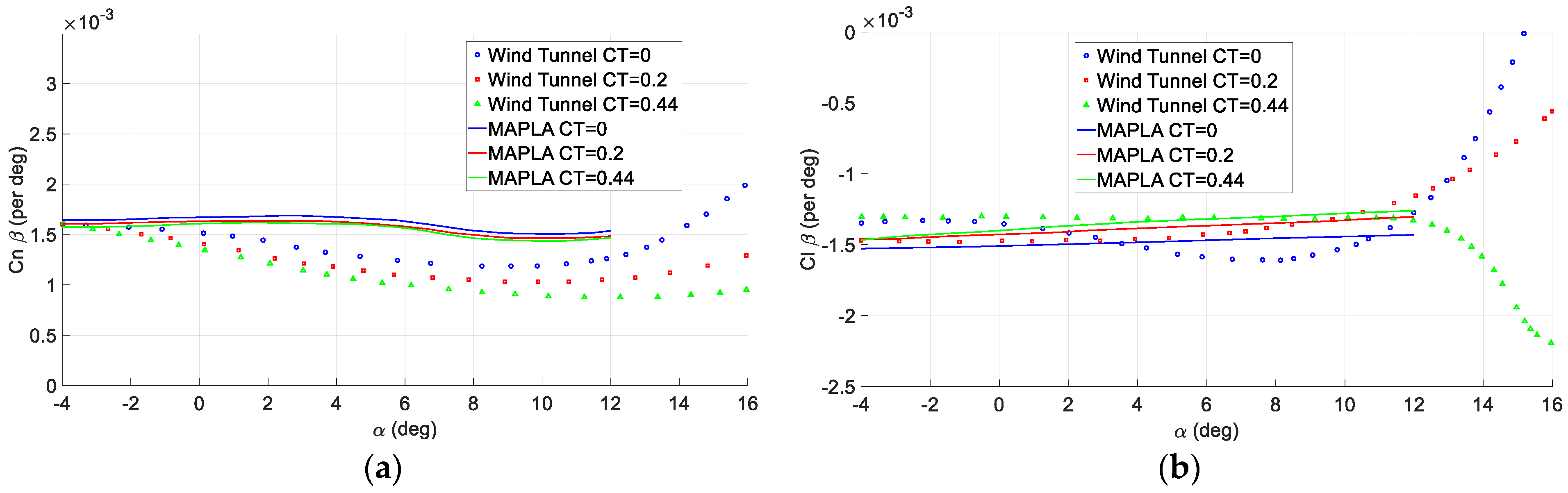
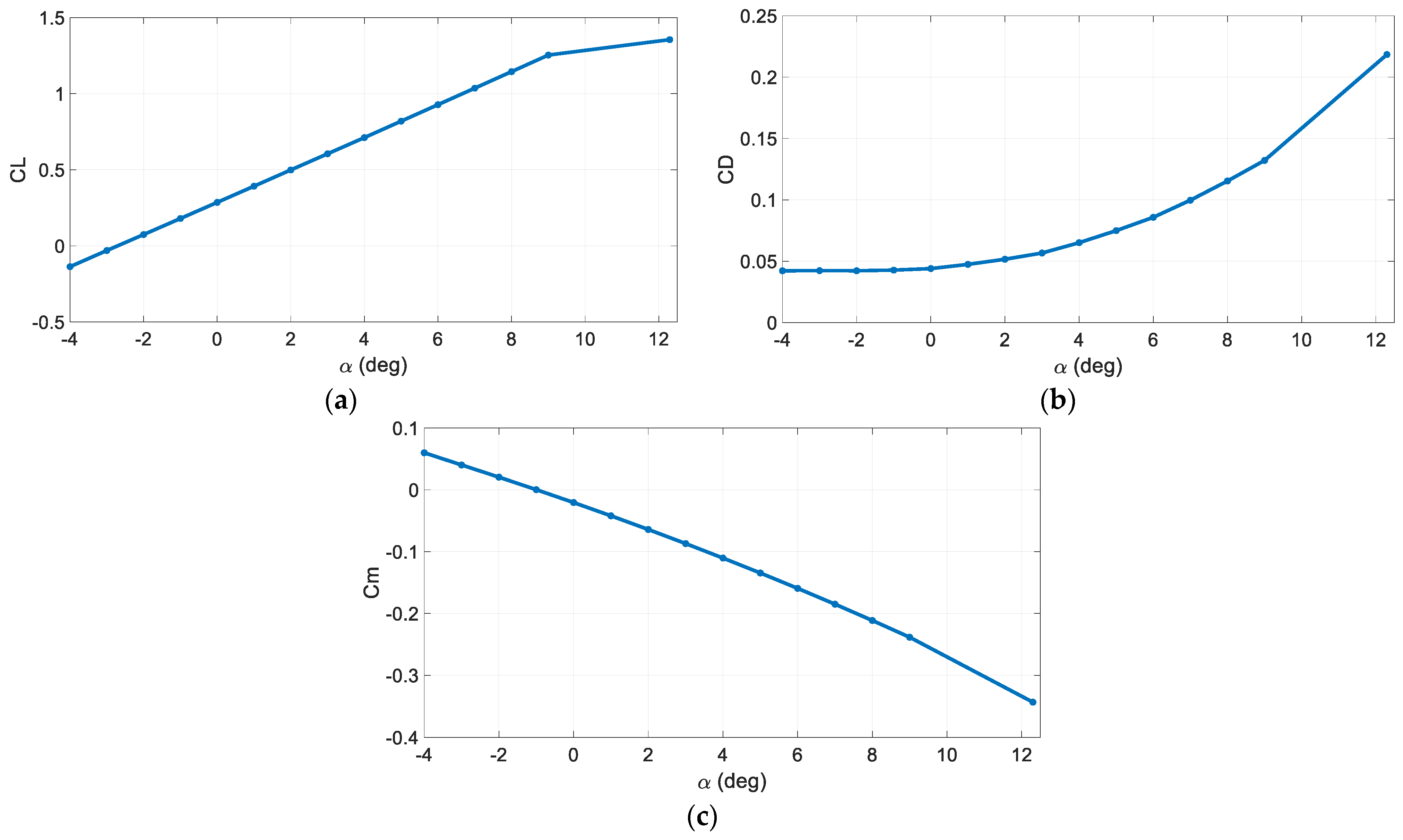
In the following, in Figure 4a–c, the longitudinal aerodynamic characteristics of the investigated airplane are presented for the corresponding flight condition. Figure 5a,b presents the lateral-directional aerodynamic characteristics of the twin-engine propeller-driven small aircraft using MAPLA and the available wind tunnel test results [44,45]. Compared to the longitudinal characteristics, the lateral-directional results show higher deviation from the wind tunnel test results. A probable reason for this deviation could be the propeller effects and power contributions. Particularly, these effects change the flow characteristics over the empennage and change its contribution to aerodynamics.
2.2. Initial Design and Sizing of the Propulsion System
To size the electric propulsion system, the number of engines needs to be selected first. Deciding between having fewer larger engines or several smaller engines requires consideration of the following factors [46]:
- Disk loading: bigger propeller disk is better in hover due to lower disk loading.
- Ground clearances: smaller propellers would result in more ground clearance when the horizontal tail and the wing are in a horizontal position.
- Propeller-wing interaction: larger propellers would have a higher slipstream height, which results in more lift because of the propeller slipstream in the same slipstream speed.
- Propeller-propeller interaction: smaller propellers with lower slipstream heights allow easier placement of the engines such that the horizontal tail propellers do not lose their slipstream. This slipstream loss can lead to a reduction in thrust from the horizontal tail propellers and an increase in noise emissions.
- Blade rotation mechanism: using very small propellers makes it more difficult to alter the pitch of the blades.
- Safety in OEI conditions: using more and smaller engines, a failure of one would result in less effect on controllability in hover and on a loss of thrust.
The aircraft features two sets of electric engines with variable-pitch and variable-speed open rotors with six blades, and it was decided to use the same size to minimize differences in propeller loading and provide cheaper manufacturing. A great proportion of the engines are placed on the wing as it is closer to the CG location and requires higher thrust during hover. After considering the criteria for the number of engines and using MAPLA’s electric propulsion module, the desired number of engines was found to be 12 (8 for the wing and 4 for the horizontal tail) with a radius of 0.5 m and a maximum allowable rpm level of ~4800. For controllability purposes, the maximum thrust-to-weight ratio was found to be approximately 1.5. For an MTOW of 2500 kg and 12 propellers, this results in a required maximum thrust of about 3100 N per propeller with a pitch down of 45 deg. The design point for the flight condition was set to the cruise speed of 70 m/s at a 1 km altitude.
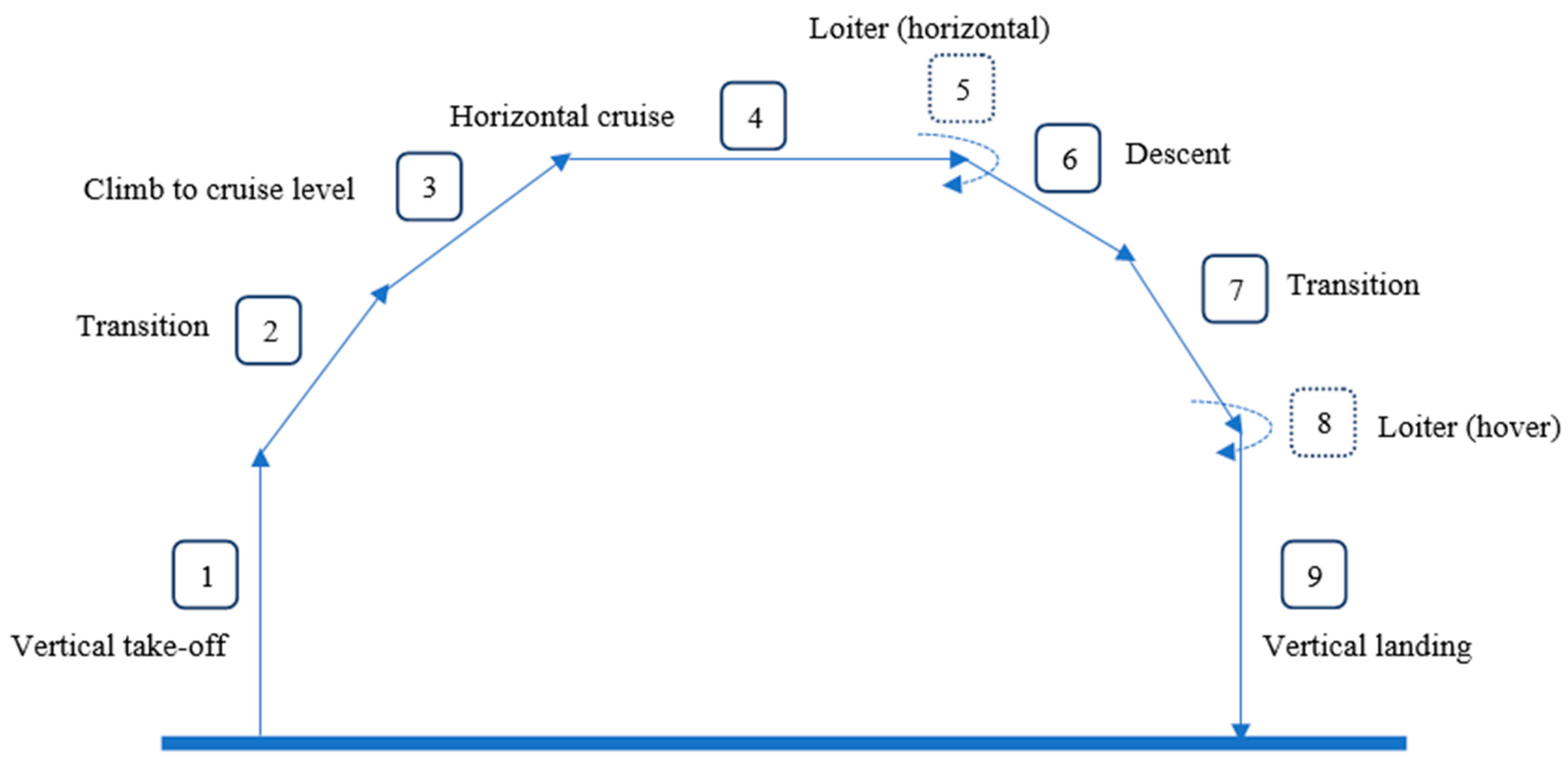
The solid-state lithium battery with a specific energy of 500 Wh/kg, a volumetric energy density of 1000 Wh/L, and a power density of 6500 W/kg was chosen. Each battery cell has an internal capacitance of 5 Ah and a nominal voltage of 3.7 V. Future-oriented battery specifications were chosen for the eVTOL tilt-wing aircraft [46]. The regular mission profile as shown in Figure 6 was defined according to the VTOL aircraft flight requirements including 1. Vertical take-off; 2. The transition from hover to climb; 3. Climb to cruising altitude; 4. Cruise; 5. Loiter in horizontal flight; 6. Descent; 7. Transition to hover; 8. Loiter in hover; and 9. Landing [46].
To calculate the energy used during flight using the method presented in [46], thrust at different flight regimes was calculated and converted to power. Accordingly, for take-off and landing, the following relation was used:
where T accounts for the thrust, V∞ is the speed perpendicular to the propeller disk, factor k corrects for the power losses, equal to 1.2 in this case, and A is the disc area.
To calculate the required thrust during take-off and landing the following equations of motion were used [46].
where represents the rotated wing incidence with respect to the horizontal axis, x-axis, and and are the corresponding accelerations in the x-axis and y-axis, respectively. To find the fuselage drag contribution, it was assumed that the fuselage is at 90 degrees when flying vertically.
For cruise flight conditions, the suggested relation from [46] for power estimation was used
where η is the propulsive efficiency at the given speed for cruise flight conditions. Finally, the required energy to be stored by batteries for the entire mission profile can be calculated by [46,47]
Consequently, the energy required for a 300 km range flight with 15 min loiter (~86 min) using equations 1 through 5 was estimated to be ~1400 MJ with a maximum power requirement during take-off of ~2.1 MW.
To calculate the battery weight, the following equations according to the energy demands and maximum power were used [46]
where DoD is the depth of discharge and EOLC is the end-of-life capacity, and they are both varying between 0 and 1. And the volume of the battery was estimated using [46]:
where is the specific energy in Wh/kg and stands for the volumetric energy density in Wh/m3 [46]. Consequently, using MAPLA’s electric propulsion module with the total energy and maximum power requirements, the total battery mass for energy storage was estimated to be 776 kg with a required volume of 0.4 m3.
In the following, the total voltage of batteries and the total current, assuming they are connected in series are presented [46].
where is the capacity and stands for nominal cell voltage. Also, the required number of battery cells for the electric engines obtained from [46]
where describes the number of battery cells, stands for the energy percentage that goes into the motors and is the energy stored in each individual cell. However, the relation requires additional corrections as a battery package not only needs to provide energy but also requires the correct voltage. Accordingly, the number of batteries required could be calculated using the following relations considering parallel and series connections [46].
The total number of battery cells for the electric propulsion system and other electronic devices was estimated to be 20,763. Based on the required voltage of 500 V for motors taken from Calnetix [46], using MAPLA’s propulsion module, the number of cells in series is 135 and the required number of battery cells in parallel arrangement is 154 which would result in 20,790 cells due to rounding. As for the proposed eVTOL aircraft, 12 propellers were selected and 2 batteries were required for each engine, giving a total of 24 batteries. Hence, the total number of battery cells in parallel should increase to 164 to allow the modular set of 7 cells in parallel for 24 batteries. Consequently, the total number of cells will be 22,140 with a total mass of 827 kg and a volume of about 0.43 m3.
2.3. PBDO Method Outline
A deterministic gradient optimizer was coupled to a possibility-evaluation algorithm to carry out the design optimization under uncertainty. This gives a comparable framework to the Sequential Optimization and Reliability Assessment (SORA) method developed for use with PBDO [48,49]. Here, the Performance Measure Approach (PMA) was used to implement the possibility evaluation on each constraint. This algorithm employs a separate optimization loop to find the worst-case scenario for each individual constraint. Using this, the value of each uncertain variable is determined within its possibilistic interval and adjusted to ensure that even in extreme cases the constraints will not be violated by an implementation of the output design [37,50]. After this step, for each iteration, a deterministic optimization followed to progress the design. This method of interwoven optimization and possibility evaluation, here achieved by applying Sequential Quadratic Programming (SQP) for each, allows the design to be iteratively altered until a final configuration is selected which is guaranteed to adhere to the constraints [37].
The MDF approach is a single-level MDO procedure where the shared design and coupling variables are consistent across all disciplines, achieved by using an MDA loop. The MDA loop starts with the given design variable states, x and z, introduced by the optimizer using an initial estimation of the coupling variable vector, y. Each discipline is then computed sequentially to update its coupling variable using values from the output of the previous discipline. The loop continues until the coupling variable vector converges. The mathematical representation of a deterministic MDF approach for an optimization problem is presented as follows:
where the shared design variables are defined by z and the local design variables are defined by x. The coupling variables, y, are found using an MDA loop each time the system and the local variables are updated.
The mathematical representation of a reliability-based MDF approach that was used in this study is shown as follows:
where P is the probability of feasibility for each constraint and p is the uncertain parameters. The optimizer alters z and x. The coupling variables, y, are estimated internally by the MDA loop and are not in the system optimizer.
The IDF method was used to reduce the iterations of the computationally costly MDA loop by eliminating the feasibility for every design assessed by the optimizer. Design feasibility, or rather the consistency of the coupling and shared variables, is only assured at the end. New auxiliary constraints are defined to reduce the discrepancy between the discipline responses and the estimated quantities at the optimum point. The mathematical representation of a deterministic IDF approach for an optimization case is presented as follows:
where the coupling variables, , are determined by calculating each discipline’s result using the coupling variable states, , defined by the system optimizer. The coupling variables, , are defined for the system optimization variables in the IDF-based PBDO method considering the auxiliary constraints. With respect to the PMA-based reliability analysis,
IDF approaches are also achievable using a revised reliability analysis loop with a double loop or sequential PBDO methods.
Validation of the implemented framework was completed previously [43]. Accordingly, the following nonlinear single-discipline PBDO test example was solved with various methods [51,52]:
Table 2 shows the results of the comparison between various methods including the double-loop PMA approach, the double-loop Reliability Index Approach (RIA), and the sequential PMA method.
Of the tested configurations, the single-loop approach diverged from PMA and RIA methods for large values of and as such, was not selected. Overall, the PMA method was found to require fewer iterations when compared to its RIA counterparts; with the sequential PMA approach requiring fewer iterations than its double-loop implementation. For this reason, it was the approach that was ultimately selected, with the hope that fewer iterations for this problem would translate to a more rapid aircraft optimization process.
The speed and stability of this method were also assessed by running the optimization procedure through 100 starting values. It was found to, on average, have an error below %, and require less time than the double loop methods [43].
For further validation of the MDO methodology, the following multi-discipline problem was solved and compared with different methods [43,53].
where the uncertain variables of and were considered to have a variation coefficient of 0.04 defined as the standard deviation, , to the random variable mean value, . After solving the problem using different methods at a reliability level of and finding the optimum points, the results are presented along with the number of function evaluations, in Table 3.
The results indicated that the IDF method with a sequential PMA strategy for the PBDO method achieved the most efficient results. Although MDF-based methods were also accurate, the effort needed to solve the problem and find the most optimized case with regard to the was considered to be excessive.
3. MDO Framework
3.1. Methods
The optimization framework is similar to the one used for Example 1 and Example 2 and the IDF/Sequential/PMA method with an SQP optimization procedure was implemented. The algorithm consists of a PBDO solver coupled with MAPLA’s different disciplines including aerodynamics, mass and balance, electric propulsion, along with stability and control.
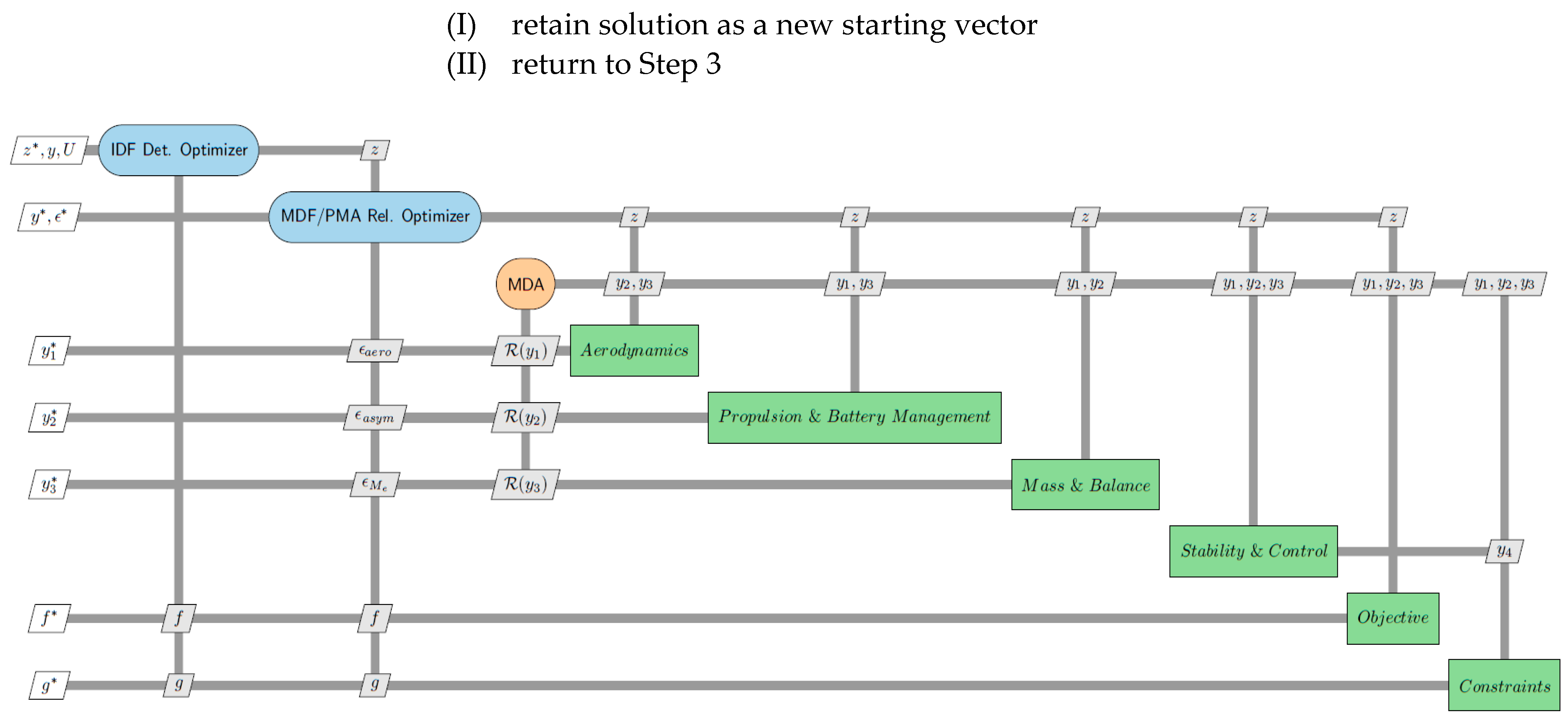
Considering various disciplines of aerodynamics, mass and balance, electric propulsion and battery management, as well as stability and control, the XDSM block diagram in Figure 7 is described for the MDO of the eVTOL tilt-wing aircraft. Accordingly, to run the system-level optimizer, each sublevel was estimated sequentially with the result of one discipline used by another. Accordingly, the empennage and wing surface areas were optimized to achieve minimum drag based on the shape parameters presented and described in section III.B and the corresponding flight environment. The framework is described in the following and the corresponding XDSM flowchart [54] is presented in Figure 8. The steps for the approach are as follows:
- Determine the estimated errors
- (I)
- Model each entry based on the horizontal/vertical tails, wing model and battery management
- (II)
- Calculate the aerodynamics of the eVTOL tilt-wing aircraft
- (III)
- Apply the uncertainty analysis
- (IV)
- Use the best-fit PDF curve for each uncertainty
- Select the initial vector and a set of reliability indices
- Run the IDF-based deterministic optimization
- Run the MDF-based PMA reliability assessment at the current reliability index, and change variables based on the sequential method
- Check for convergence based on the current reliability goal
- (I)
- if yes, update starting vector with the current optimum point, select the next reliability goal and return to Step 3
- (II)
- if no, return to Step 3
- Advance to the next target reliability level
- (I)
- retain solution as a new starting vector
- (II)
- return to Step 3
3.2. Design Variables
Since, in this work, the focus was to optimize the wing and empennage of the eVTOL aircraft, the corresponding variables were chosen based on the semi-empirical analysis’s sensitivities considering the effectiveness of each component with respect to the semi-empirical analysis sensitivity. These variables are presented in Figure 8, Figure 9 and Figure 10. In addition to the horizontal/vertical tail and wing components, battery placement was also parametrized because of its effect on the desired center of gravity location to minimize manufacturing penalties. A list of the design variables considered in this study is supplied in Table 4.
The wing surface area was determined using Equation (17) considering the shape parameters depicted in Figure 8:
where is the extended panel out of the wing tip chord and is achieved in Figure 8 by the trailing edge angle of the wing.
And can be calculated using the
where is the wing trailing edge sweep angle and can be achieved by Equation (19) as follows.
The surface area of the horizontal tail was estimated using Equation (21) considering the shape parameters presented in Figure 9 as follows.
where is the extended panel out of the horizontal tail tip chord and can be seen in Figure 9 by the horizontal tail trailing edge angle as follows.
And can be calculated using the
where is the horizontal tail trailing edge sweep angle and can be achieved by Equation (24) as follows.
Similarly, the surface area of the vertical tail was determined using Equation (25), based on the shape parameters defined in Figure 9:
where is the extended panel out of the vertical tail root chord and could be achieved using the trailing edge sweep angle with the following equation.
3.3. Disciplines
3.3.1. Aerodynamics and Stability
The first discipline in this study was aerodynamics consisting of longitudinal and lateral-directional aerodynamic coefficients and stability derivatives. MAPLA’s aerodynamics module was used and was originally developed based on the work accomplished by NASA [44,45]; however, to generalize the platform and enhance the work, particularly for the purpose of small aircraft design and development, some changes were made to include the following features [39]:
- The maximum lift of a twisted wing
- The zero-lift pitching moment of the twisted wing
- The drag of the twisted wing
- The high-lift surfaces
- Lift of the horizontal tail and elevator surfaces
- The drag of the control and high-lift surfaces
The aerodynamics module results were compared against the wind tunnel test data in section II.A. In addition, the aerodynamics module results were compared with wind tunnel test data of a small aircraft at a scale of 1:3, the estimations provided by the DATCOM, and a VLM-based prediction in our previous work [39]. The results indicated that the aerodynamics module was able to determine the aerodynamic characteristics of the small aircraft with acceptable accuracy from zero-lift to stall conditions in all configurations. For the purpose of this study, aerodynamic characteristics were first estimated for each component of the tailless eVTOL tilt-wing aircraft, while running the optimization system, the horizontal/vertical tail contribution was also added to the calculations to consider the contributions of the fixed part of the empennage and high-lift surfaces. In the next step, the static stability derivatives were determined, and the characteristics were found by integrating the contributions of each component of the eVTOL tilt-wing aircraft. After that, the dynamic stability of the eVTOL tilt-wing aircraft was calculated with static stability characteristics.
3.3.2. Weight and Balance
The next discipline was weight and balance where the weight of each part was estimated using statistical estimations [55,56]. The weights were determined in accordance with the MIL-STD-1374 through a “Summary Group Weight Statement” for light aircraft. Both the mass and center of gravity of each part were estimated using statistical relations to provide the total empty weight of the eVTOL tilt-wing aircraft [57,58]. Finally, the moments of inertia calculations were carried out for , and using the following relations [55]:
where b is the wingspan in m, W is the total weight in kg and is the length of the fuselage in m.
3.3.3. Handling Quality
The next discipline was control where the handling quality of the aircraft was evaluated using MAPLA’s Flying Quality subprogram. It enables the assessment of the trim characteristics of the aircraft in different flight conditions and aircraft configurations, hence presenting the handling quality level for all longitudinal and lateral-directional modes in accordance with the regulations. By altering mass, the moment of inertia, geometry, aerodynamic coefficients, stability derivatives, the centre of mass, and the handling qualities of the eVTOL tilt-wing airplane were assessed. Hence, having the required aerodynamic characteristics, trim conditions were applied to generate the data for the trimmed flight. Accordingly, elevator deflection, aircraft angle of attack and power values were estimated considering the trim flight as follows [42,43]:
The perturbed equations of motion of the eVTOL tilt-wing aircraft were modelled based on the small perturbation equations. Having the transfer function for each case, the corresponding damping ratio and natural frequency were calculated and stored to be used for the handling quality analysis. Then, using airworthiness and aviation regulation requirements for small aircraft, particularly from CS-23, CS-27, CS-29, or CS-25 and available information from military regulations for aircraft dynamic modes, the aircraft handling quality level for different longitudinal and lateral-directional modes were estimated and ranked from 1 to 4. Level 1 denotes the best flying quality, while Level 4 represents poor flying quality for the aircraft mode [42,43].
3.3.4. Battery System
Finally, the battery system sizing and placement were estimated to find the optimum location scenario to keep the aft and forward CG positions in the desired locations for manufacturing purposes. Hence, considering the number of battery cells as 22,140 in total for a range of 300 km with 15 min loiter (~86 min) based on the results from the initial propulsion system sizing presented in section II.B, the arrangement of the battery package optimized. Accordingly, the battery sets were divided into two compartments where an optimization process was conducted to find the number of cells and the distance of each one of the compartments from the nose of the airplane that could compromise the required number of cells in total while maintaining the most aft and forward CG positions (e.g., 27% and 10%, respectively) in the desired manufacturing position of the base aircraft.
3.4. Objective Function
An objective function to guide the design was required for this investigation, selected to achieve the minimum drag force of the components while satisfying the design constraints of the total aircraft. Accordingly, the Stability and Control module of MAPLA was employed while running the optimization algorithm to find the trim condition in the cruise and the corresponding drag force. The contributions of each component to the total drag of the eVTOL tilt-wing aircraft are summarized here:
- Zero-lift drag contribution of the wing, horizontal tail, and vertical tail.
- Zero-lift drag contribution of the fuselage and nacelles.
- Zero-lift interference drag contribution of the components.
- Drag contribution of the wing and empennage package at the angle of attack.
- Drag contribution of the fuselage and nacelle at the angle of attack.
- Wing-fuselage interference drag contribution at the angle of attack.
Accordingly, the main objective was defined to minimize the total drag of the eVTOL tilt-wing aircraft using Equation (33).
Main objective:
3.5. Constraints
A series of constraints were imposed on the optimization problem. Starting with the manufacturing constraints were applied to define the maximum and minimum acceptable values for each variable. Considering historical data and initial weight and balance estimation, the empty mass of the eVTOL tilt-wing airplane was restricted to less than 1600 kg. According to the Special Condition for small-category VTOL aircraft by EASA light aircraft certification requirements and CS-27, small rotorcrafts, the weight of the eVTOL must be less than 3175 Kg [59]. Static and dynamic characteristics requirements were also set as constraints for the optimization model. Moreover, the effectiveness of the control surfaces during cruise and climb-out flights was determined to guarantee adequate pitch authority as accomplished in slow flights.
Regulation compliance for VTOL aircraft according to the Means of Compliance (MOC) with the Special Condition VTOL aircraft from EASA [60], should use regulations from CS-23, CS-27, CS-29, or CS-25 unless specifically indicated by the MOC VTOL. Accordingly, for the case of the proposed eVTOL tilt-wing aircraft regulations are considered from CS-23 for light aircraft.
A negative value for was required to achieve longitudinal static stability. Typically, for light aircraft should be around −0.3 to −1.5 1/rad. Regarding longitudinal dynamic stability, a negative value for the real part of the roots of the longitudinal characteristics was desired. was a key player for this criterion such that a negative value has a strong stabilizing outcome. Usually, for most small aircraft is around −5 to −30 1/rad [61]. Furthermore, a static margin of 5–10% was constrained to longitudinal stability.
A negative value for was necessary to maintain roll stability. In addition, must be positive to have directional static stability. The typical value of for most aircraft is between +0.1 and +0.4 1/rad. A negative value for the real part of the roots of the lateral-directional characteristic equation is required to maintain directional dynamic stability. is a major contributor to this criterion such that a negative value has a robust stabilizing effect. The typical value for most aircraft is between −0.1 and −1 1/rad [62]. For a full-thrust climb scenario in OEI flight circumstances, yaw static stability must be ensured. The constraint ensures that the rudder and vertical tail have adequate authority [63,64,65,66].
Airworthiness requirements for small airplanes were considered, principally from the CS-23 standard for aircraft dynamic modes and defined as constraints for the optimization model. All constraints are listed in Table 5.
3.6. Source of Uncertainty
In this example, instead of using a uniformly distributed random parameter for the error term of aero uncertainty, a nonuniform approach was used where each aerodynamic characteristic presented in Table 6 had a specific error term according to the similar aircraft model used as the base for the design of the new aircraft [44,45]. Accordingly, the error term is considered to be distributed between the maximum and minimum detected value. The error factor was defined as the ratio of estimated aerodynamic results to the observed data from the original database, . The aerodynamics results estimated using MAPLA’s Aerodynamics module were then scaled by this ratio. The error factor determined by Equation (34) was set to be nonuniformly distributed according to the deviation results shown in Table 6.
The aircraft models from the compiled database were used and the calculated empty mass of each one was compared with the original results from the database. Equation (35) was used to define the mass error factor. Hence, empty-mass calculations were determined by MAPLA first and scaled by the error factor to consider the uncertainty in the estimation of the eVTOL tilt-wing aircraft mass.
4. Results
After running the optimization process considering both the constraints and uncertainties, the resulting characteristics of the aircraft are presented in Figure 11, generated by the Geometry module of MAPLA. The resulting variables are discussed in Table 7.
The results for the aerodynamic characteristics of the optimized eVTOL aircraft, by using the proposed multidisciplinary possibilistic approach, are presented for cruise flight conditions at an airspeed of 70 m/s. Figure 12 depicts the results for the longitudinal static characteristics for the optimized eVTOL aircraft configuration.
Figure 13 presents the results for the lateral-directional static characteristics of the optimized eVTOL tilt-wing aircraft in cruise flight conditions.
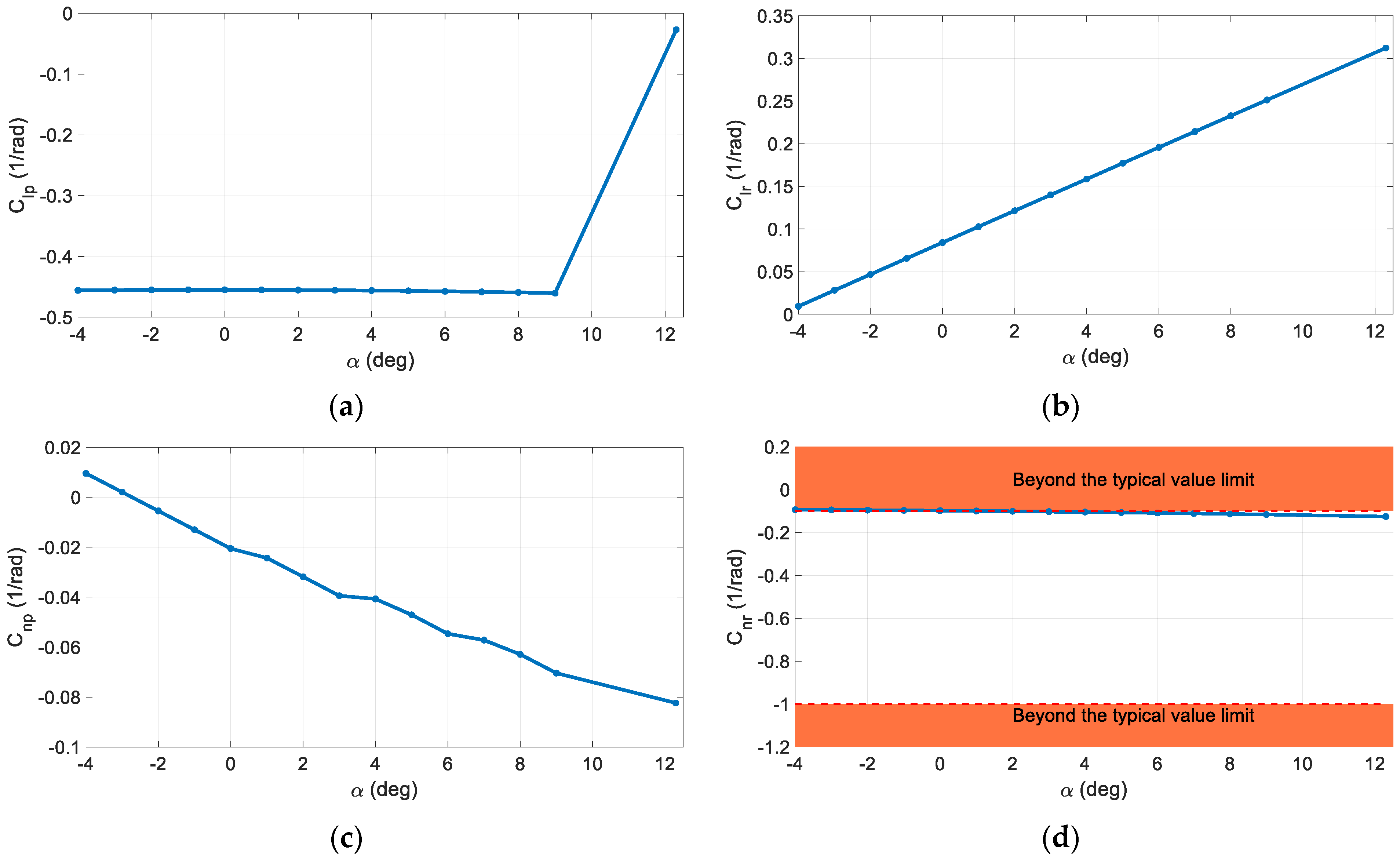
Figure 14 shows the results for the longitudinal dynamic characteristics of the optimized eVTOL tilt-wing aircraft in cruise flight conditions.
In the following, the dynamic stability results for the optimized eVTOL tilt-wing aircraft in horizontal flight are presented. As can be seen, all periodical modes were stable for the eVTOL tilt-wing aircraft at the tested speeds and flight conditions. The stability characteristics were defined as constraints for the optimization model. The constraints were implemented considering a penalty for any scenarios out of the boundaries. It should be noted that all results have been considered for the maximum weight and the aftmost CG location as the worst-case scenario.
With respect to the CS-23 standards [67], the phugoid mode was noted as not strong. In Figure 15, the phugoid mode damping ratio considering the MIL airworthiness requirements for this aircraft type is shown [68,69]. As was visibly apparent, the damping characteristics completely satisfied the Level 1 handling quality for all considered speeds. With respect to Figure 16 presents the time to double for the phugoid amplitude. As can be seen, the oscillations were stable and negative all the time.
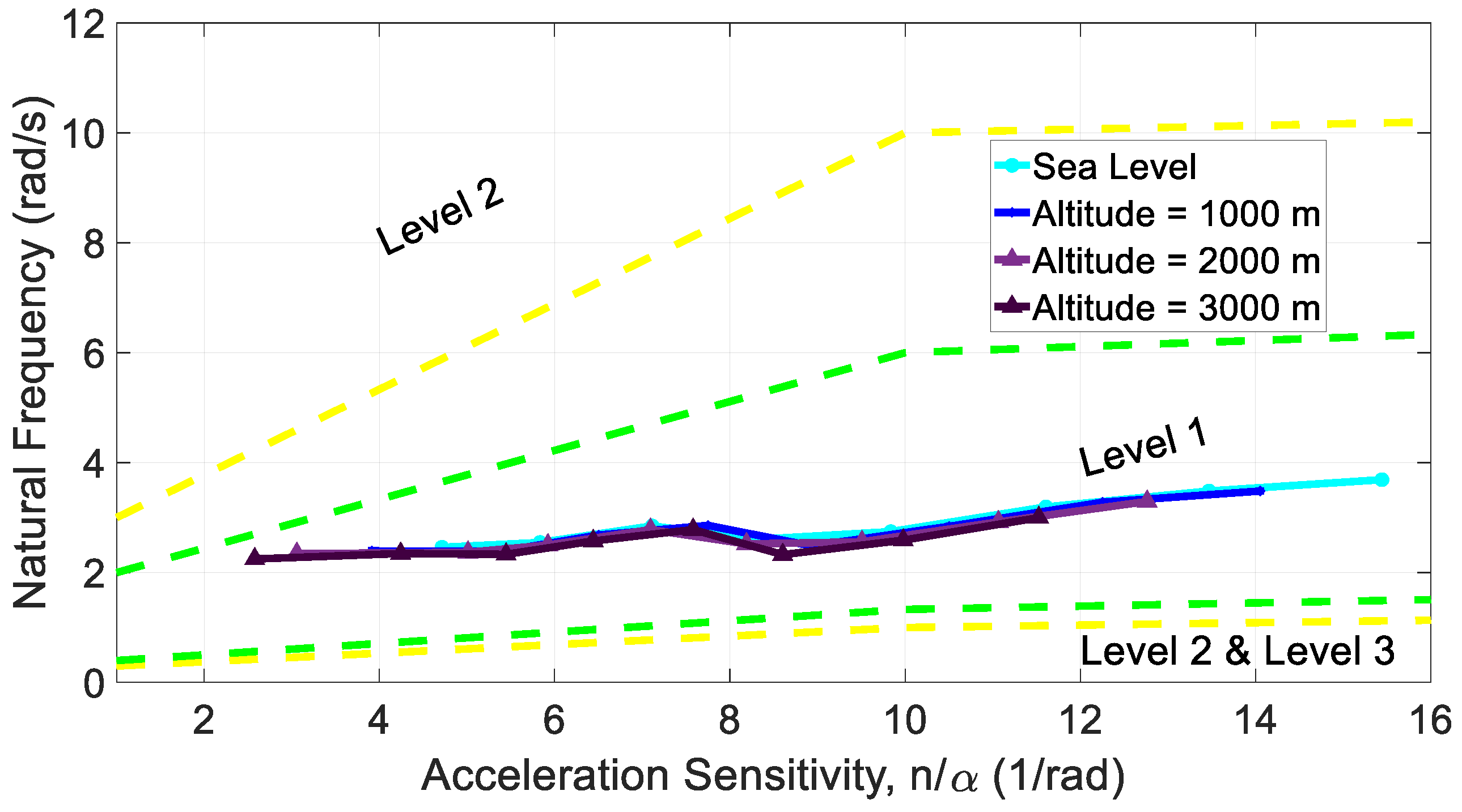
For Short Period oscillations, according to the CS-23 criteria, the characteristics were very significant. With respect to Figure 17 which shows the short period undamped natural frequency against different acceleration sensitivity values, the results met the Level 1 requirements according to MIL requirements [70]. Furthermore, Figure 18 presents the damping ratio values for the short period mode, which nicely satisfies Level 1 of handling quality according to the CS-23 criteria [34].
With respect to CS-23.181, the Dutch roll oscillations between the stalling speed and the maximum speed must be damped to 1/10 amplitude in seven cycles. Figure 19 demonstrates that this requirement has also been met.
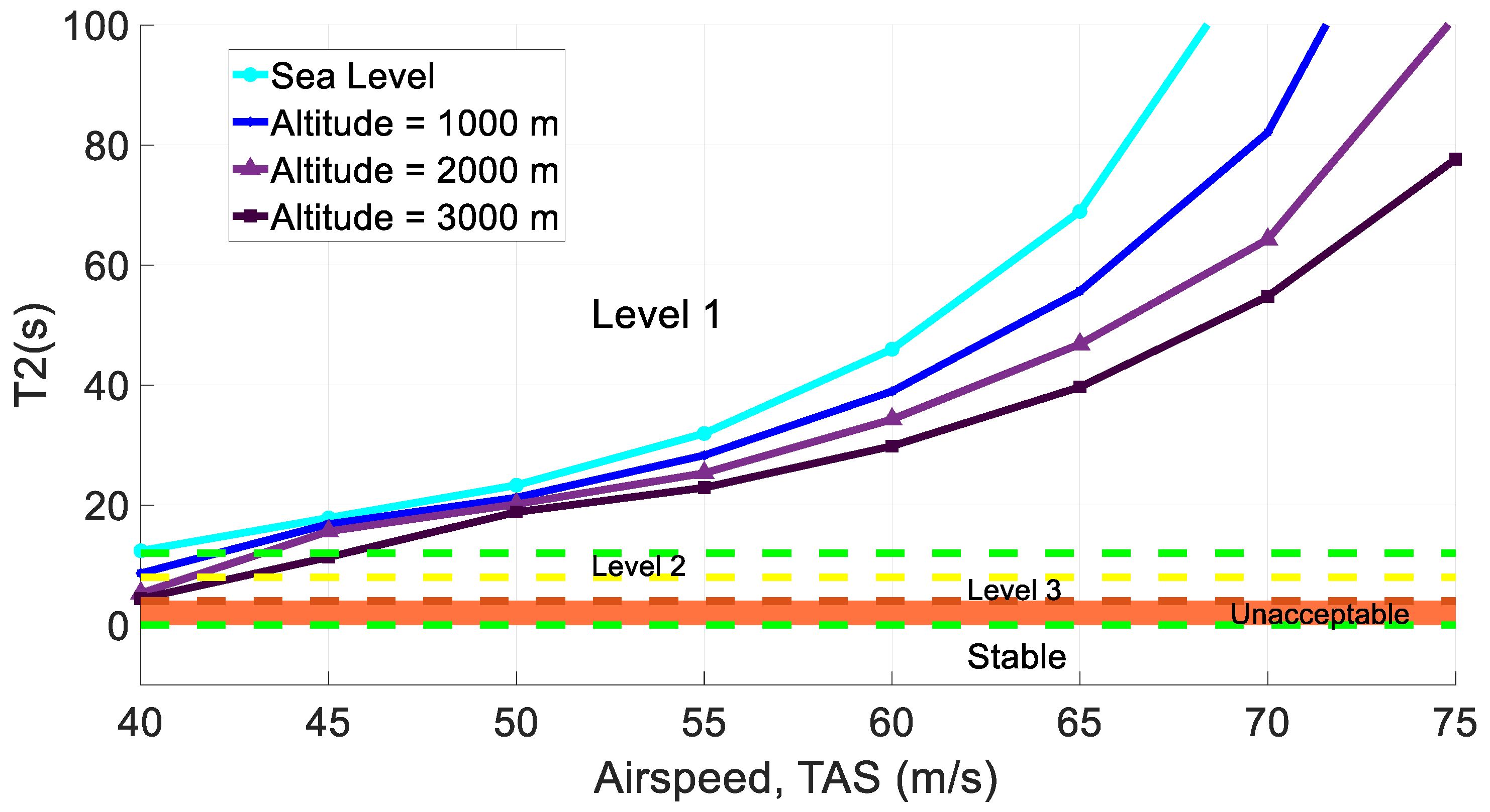
With respect to Figure 20, the roll mode was effectively damped. Also, as shown in Figure 21 where the spiral mode characteristics are presented, the values for time to double show that the spiral mode is damped according to the requirements defined in CS-23 and MIL-F-8785-C [34,67]. Complying with both procedures, the spiral mode shows Level 1 of handling quality.
5. Conclusions
The projected multidisciplinary possibilistic method effectively presented the capability to optimize the eVTOL tilt-wing airplane by changing the geometry of the empennage package as well as wing and battery placement in the early design phases where several uncertainties exist because of low fidelity calculations. In this example, the disciplines of aerodynamics, propulsion, weight and balance, and stability and control were considered. With respect to different design characteristics, including longitudinal/lateral/directional trim, stability and control characteristics, and other criteria, the resulting eVTOL tilt-wing aircraft provided the optimized design with the desired characteristics to ensure that airworthiness requirements were met, and predefined constraints were complied with. The proposed approach may be used as a basis for light aircraft companies to upgrade their current products to the eVTOL versions. The resulting eVTOL design will be not only an optimized version but one where the stability of the aircraft is guaranteed. With this, the manufacturers of small companies can enhance the design and development of new aircraft without some of the costs associated with the older development methods, primarily because many of the required considerations in the conceptual design phase have been handled by the proposed approach.
Author Contributions
Conceptualization, M.R. and J.C.; Methodology, M.R., J.B., D.N. and J.C.; Software, M.R., D.N. and J.B.; Formal analysis, M.R. and D.N.; Writing—original draft, M.R. and J.B.; Preparation, M.R. and J.B.; Data curation, M.R. and J.B.; Writing—review and editing, J.B., D.N. and J.C. All authors have read and agreed to the published version of the manuscript.
Funding
This work was funded by Mitacs through the Mitacs Accelerate Program (reference number: IT16648) and Columbiad Launch Services Inc.
Institutional Review Board Statement
Not applicable.
Informed Consent Statement
Not applicable.
Data Availability Statement
Not applicable.
Conflicts of Interest
The authors declare no conflict of interest.
Nomenclature
| Roman Symbols | |
| A | disk area |
| a | acceleration |
| b | span |
| capacity | |
| CD | drag coefficient |
| CL | lift coefficient |
| ratio of the moveable surface chord to fixed surface chord | |
| root chord | |
| tip chord | |
| drag | |
| energy | |
| specific energy | |
| the volumetric energy density | |
| dt | time step |
| Fx | X component of the force acting on the vehicle |
| Fy | Y component of the force acting on the vehicle |
| G | generic functions |
| h | altitude |
| incidence angle | |
| k | correction factor for the power losses |
| L | lift |
| l | distance, from the fuselage nose to the mean aerodynamic chord, parallel to X-axis |
| mass of the battery | |
| the number of cells | |
| P | power |
| T | thrust |
| the speed perpendicular to the propeller disk | |
| the nominal cell voltage | |
| the total voltage of batteries | |
| the volume of the battery | |
| Y | the coupling variable |
| distance, from the quarter chord of the horizontal tail mean aerodynamic chord to the X-axis, parallel to Z-body axis, positive down | |
| Greek Symbols | |
| the rotated wing angle with respect to the x-axis | |
| trailing edge sweep angle | |
| sweep angle | |
| dihedral | |
| density | |
| the propulsive efficiency at the given speed | |
References
- Straubinger, A.; Rothfeld, R.; Shamiyeh, M.; Büchter, K.D.; Kaiser, J.; Plötner, K.O. An overview of current research and developments in urban air mobility—Setting the scene for UAM introduction. J. Air Transp. Manag. 2020, 87, 101852. [Google Scholar] [CrossRef]
- Kuhn, H.; Falter, C.; Sizmann, A. Renewable Energy Perspectives for Aviation. In Proceedings of the 3rd CEAS Air&Space Conference and 21st AIDAA Congress, Venice, Italy, 24–28 October 2011; pp. 1249–1259. Available online: https://www.researchgate.net/publication/271457052 (accessed on 20 May 2022).
- Rezende, R.N.; Barros, J.E.M. General aviation 2025—A study in electric propulsion. In Proceedings of the 2018 Joint Propulsion Conference, Cincinnati, OH, USA, 9–11 July 2018. [Google Scholar] [CrossRef]
- Hoelzen, J.; Liu, Y.; Bensmann, B.; Winnefeld, C.; Elham, A.; Friedrichs, J.; Hanke-Rauschenbach, J. Conceptual Design of Operation Strategies for Hybrid Electric Aircraft. Energies 2018, 11, 217. [Google Scholar] [CrossRef]
- Wentz, W.H.J.; Mohamed, A.S. Preliminary Design Considerations for Zero Greenhouse Gas Emission Airplanes. SAE Trans. J. Aerosp. 2004, 113, 1–16. [Google Scholar]
- Kohout, L.L.; Schmitz, P.C. Fuel cell propulsion systems for an all-electric personal air vehicle. In Proceedings of the AIAA International Air and Space Symposium and Exposition: The Next 100 Years, Dayton, OH, USA, 14–17 July 2003. [Google Scholar] [CrossRef]
- Nickol, C.L.; Guynn, M.D.; Kohout, L.L.; Ozoroski, T.A. High altitude long endurance air vehicle analysis of alternatives and technology requirements development. In Proceedings of the 45th AIAA Aerospace Sciences Meeting and Exhibit, Reno, CA, USA, 8–11 January 2007; pp. 12653–12669. [Google Scholar] [CrossRef]
- Romeo, G.; Frulla, G.; Cestino, E.; Corsino, G. HELIPLAT: Design, aerodynamic, structural analysis of long-endurance solar-powered stratospheric platform. J. Aircr. 2004, 41, 1505–1520. [Google Scholar] [CrossRef]
- Youngblood, J.W.; Talay, T.A. Solar-Powered airplace design for long-endurance, high-altitude flight. In Proceedings of the 2nd International Very Large Vehicles Conference, Washington, DC, USA, 17–18 May 1982. [Google Scholar] [CrossRef]
- Choi, T.P.; Soban, D.S.; Mavris, D.N. Creation of a design framework for all-electric aircraft propulsion architectures. In Proceedings of the 3rd International Energy Conversion Engineering Conference, San Francisco, CA, USA, 15–18 August 2005; pp. 373–383. [Google Scholar] [CrossRef]
- Himansu, A.; Freeh, J.E.; Steffen, C.J.; Tornabene, R.T.; Wang, X.Y.J. Hybrid solid oxide fuel cell/Gas turbine system design for high altitude long endurance aerospace missions. In Proceedings of the Fourth International ASME Conference on Fuel Cell Science, Engineering and Technology, Irvine, CA, USA, 19–21 June 2006. [Google Scholar] [CrossRef]
- Jansen, R.H.; Bowman, C.L.; Clarke, S.; Avanesian, D.; Dempsey, P.J.; Dyson, R.W. NASA electrified aircraft propulsion efforts. Aircr. Eng. Aerosp. Technol. 2020, 5, 667–673. [Google Scholar] [CrossRef]
- Ghassemi, M.; Barzkar, A.; Saghafi, M. All-Electric NASA N3-X aircraft electric power systems. IEEE Trans. Transp. Electrif. 2022, 8, 4091–4104. [Google Scholar] [CrossRef]
- Jansen, R.; Bowman, C.; Jankovsky, A.; Dyson, R.; Felder, J. Overview of NASA electrified aircraft propulsion (EAP) research for large subsonic transports. In Proceedings of the 53rd AIAA/SAE/ASEE Joint Propulsion Conference, Atlanta, GA, USA, 10–12 July 2017; p. 4701. [Google Scholar]
- Haglage, J.M.; Brown, T.W. Nasa electric aircraft testbed (Neat) reconfiguration to enable altitude testing of megawatt-scale electric machines. In Proceedings of the 2020 AIAA/IEEE Electric Aircraft Technologies Symposium (EATS), New Orleans, LA, USA, 26–28 August 2020; pp. 1–13. [Google Scholar]
- Zhao, J.; Ramadan, H.S.; Becherif, M. Metaheuristic-based energy management strategies for fuel cell emergency power unit in electrical aircraft. Int. J. Hydrogen Energy 2019, 44, 2390–2406. [Google Scholar] [CrossRef]
- Lei, T.; Yang, Z.; Lin, Z.; Zhang, X. State of art on energy management strategy for hybrid-powered unmanned aerial vehicle. Chin. J. Aeronaut. 2019, 32, 1488–1503. [Google Scholar] [CrossRef]
- Dyson, R.W. NASA Electric Aircraft Test Bed (NEAT) Development Plan-Design, Fabrication, Installation; GRC-E-DAA-TN30267; NASA: Washington, DC, USA, 18 August 2016. [Google Scholar]
- Brelje, B.J.; Martins, J.R. Electric, hybrid, and turboelectric fixed-wing aircraft: A review of concepts, models, and design approaches. Prog. Aerosp. Sci. 2019, 104, 1–9. [Google Scholar] [CrossRef]
- Turk, I.; Ozbek, E.; Ekici, S.; Karakoc, T.H. A conceptual design of a solar powered UAV and assessment for continental climate flight conditions. Int. J. Green Energy 2022, 19, 638–648. [Google Scholar] [CrossRef]
- Lee, D.; Lim, D.; Yee, K. Generic Design Methodology for Vertical Takeoff and Landing Aircraft with Hybrid-Electric Propulsion. AIAA J. Aircr. 2022, 59, 278–292. [Google Scholar] [CrossRef]
- Anh Vu, N.; Lee, Y.; Lee, J.; Kim, S.; Jae Chung, I. Configuration design and optimisation study of a compound gyroplane. Aircr. Eng. Aerosp. Technol. 2011, 83, 420–428. [Google Scholar] [CrossRef]
- Kotarski, D.; Piljek, P.; Pranjić, M.; Grlj, C.G.; Kasać, J. A Modular Multirotor Unmanned Aerial Vehicle Design Approach for Development of an Engineering Education Platform. Sensors 2021, 21, 2737. [Google Scholar] [CrossRef]
- Krajanowski-Kaleta, J.; Zawadzki, P.; Żywicki, K.; Szymański, M.; Mróz, A. Comparison of the Tools for Design Process Automation in Popular CAx Systems. In Proceedings of the International Scientific-Technical Conference MANUFACTURING, Poznan, Poland, 16–19 May 2022; pp. 15–23. [Google Scholar]
- Parparita, M.; Bere, P.; Józwik, J.; Biruk-Urban, K. Design and Manufacturing of a Small Sized UAV Wing. In Proceedings of the 2023 IEEE 10th International Workshop on Metrology for AeroSpace (MetroAeroSpace), Milan, Italy, 19–21 June 2023; pp. 187–192. [Google Scholar] [CrossRef]
- Łukaszewicz, A.; Szafran, K.; Jóźwik, J. CAx techniques used in UAV design process. In Proceedings of the 2020 IEEE 7th International Workshop on Metrology for AeroSpace (MetroAeroSpace), Pisa, Italy, 22–24 June 2020; pp. 95–98. [Google Scholar] [CrossRef]
- Ozbek, E.; Ekici, S.; Karakoc, T.H. Unleashing the Potential of Morphing Wings: A Novel Cost Effective Morphing Method for UAV Surfaces, Rear Spar Articulated Wing Camber. Drones 2023, 7, 379. [Google Scholar] [CrossRef]
- Kao, Y.T.; Zahara, E. A hybrid genetic algorithm and particle swarm optimization for multimodal functions. Appl. Soft Comput. J. 2008, 8, 849–857. [Google Scholar] [CrossRef]
- Boggs, T.; Tolle, J.W. Sequential Quadratic Programming. Acta Numer. 1995, 4, 1–51. [Google Scholar] [CrossRef]
- Hwang, J.T.; Martins, J.R. A computational architecture for coupling hetero-geneous numerical models and computing coupled derivatives. ACM Transac-Tions Math. Softw. 2018, 44, 1–39. [Google Scholar] [CrossRef]
- Falck, R.D.; Gray, J.S. Optimal Control within the Context of Multidisciplinary Design, Analysis, and Optimization. In Proceedings of the AIAA Scitech 2019 Forum, San Diego, CA, USA, 7–11 January 2019. [Google Scholar]
- Kraft, D. A Software Package for Sequential Quadratic Programming; DLR German Aerospace Center—Institute for Flight Mechanics: Koln, Germany, 1988. [Google Scholar]
- Schittkowski, K. The nonlinear programming method of wilson, han and powell with an augmented lagrangian type line search function. Numer. Math 1981, 38, 1. [Google Scholar]
- Brandt, S.A.; Post, M.L.; Hall, D.; Gilliam, F.; Jung, T.; Yechout, T. The Value of Semi-Empirical Analysis Models in Aircraft Design. In Proceedings of the 16th AIAA/ISSMO Multidisciplinary Analysis and Optimization Conference, Dallas, TX, USA, 22–26 June 2015. [Google Scholar] [CrossRef]
- Möller, B.; Beer, M. Engineering computation under uncertainty—Capabilities of non-traditional models. Comput. Struct. 2008, 86, 1024–1041. [Google Scholar] [CrossRef]
- Ben-Haim, Y. Convex models of uncertainty: Applications and implications. Erkenntnis 1994, 41, 139–156. [Google Scholar] [CrossRef]
- Du, L.; Choi, K.K.; Youn, B.D.; Gorsich, D. Possibility-Based Design Optimization Method for Design Problems with Both Statistical and Fuzzy Input Data. J. Mech. Des. Trans. ASME 2006, 128, 928–935. [Google Scholar] [CrossRef]
- Zou, T.; Mahadevan, S.; Rebba, R. Computational efficiency in reliability-based optimization. In Proceedings of the 9th ASCE Specialty Conference on Probabilistic Mechanics and Structural Reliability, Albuquerque, NM, USA, 26–28 July 2004. [Google Scholar]
- Rostami, M.; Bagherzadeh, S.A. Development and Validation of an Enhanced Semi-Empirical Method for Estimation of Aerodynamic Characteristics of Light, Propeller-Driven Airplanes. Proc. Inst. Mech. Eng. Part G J. Aerosp. Eng. 2018, 232, 638–648. [Google Scholar] [CrossRef]
- Rostami, M.; Chung, J. Multidisciplinary Analysis Program for Light Aircraft (MAPLA). In Proceedings of the Canadian Society for Mechanical Engineering International Congress, Charlottetown, PE, Canada, 27–30 June 2021. [Google Scholar]
- Rostami, M.; Chung, J.; Neufeld, D. Vertical Tail Sizing of Propeller-Driven Aircraft Considering the Asymmetric Blade Effect. Proc. Inst. Mech. Eng. Part G J. Aerosp. Eng. 2022, 236, 1184–1195. [Google Scholar] [CrossRef]
- Rostami, M.; Chung, J.; Park, H.U. Design Optimization of Multi-Objective Proportional–Integral–Derivative Controllers for Enhanced Handling Quality of a Twin-Engine, Propeller-Driven Airplane. Adv. Mech. Eng. 2020, 12, 1687814020923178. [Google Scholar] [CrossRef]
- Rostami, M.; Bardin, J.; Neufeld, D.; Chung, J. A Multidisciplinary Possibilistic Approach to Size the Empennage of Multi-Engine Propeller-Driven Light Aircraft. Aerospace 2022, 9, 160. [Google Scholar] [CrossRef]
- Wolowicz, H.; Yancey, R.B. Longitudinal Aerodynamic Characteristics of Light, Twin-Engine Propeller-Driven Airplanes; NASA Technical Note; NASA-TN-D-6800; NASA: Washington, DC, USA, 1972. [Google Scholar]
- Wolowicz, H.; Yancey, R.B. Lateral Directional Aerodynamic Characteristics of Light, Twin-Engine Propeller-Driven Airplanes; NASA Technical Note; NASA-TN-D-6946; NASA: Washington, DC, USA, 1972; pp. 17–56. [Google Scholar]
- Alba-Maestre, J.; van Reine, K.P.; Sinnige, T.; Castro, S.G.P. Preliminary propulsion and power system design of a tandem-wing long-range evtol aircraft. Appl. Sci. 2021, 11, 11083. [Google Scholar] [CrossRef]
- Senkans, E.; Skuhersky, M.; Kish, B.; Wilde, M. A First-Principle Power and Energy Model for eVTOL Vehicles. In Proceedings of the AIAA AVIATION 2021 FORUM, Virtual Event, 2–6 August 2021; p. 3169. [Google Scholar]
- Du, X.; Chen, W. Sequential Optimization and Reliability Assessment Method for Efficient Probabilistic Design. J. Mech. Des. Trans. ASME 2004, 126, 225–233. [Google Scholar] [CrossRef]
- Du, X.; Guo, J.; Beeram, H. Sequential Optimization and Reliability Assessment for Multidisciplinary Systems Design. Struct. Multidiscip. Optim. 2008, 35, 117–130. [Google Scholar] [CrossRef]
- Youn, B.D.; Choi, K.K.; Du, L. Enriched Performance Measure Approach for Reliability-Based Design Optimization. AIAA J. 2005, 43, 874–884. [Google Scholar] [CrossRef]
- Neufeld, D. Multidisciplinary Aircraft Conceptual Design Optimization Considering Fidelity Uncertainties. Program of Aerospace Engineering. Ph.D. Thesis, Ryerson University, Toronto, ON, Canada, 2010; p. 150. [Google Scholar]
- Chiralaksanakul, A.; Mahadevan, S. First-Order approximation methods in Reliability-Based design optimization. J. Mech. Des. 2005, 127, 851. [Google Scholar] [CrossRef]
- Ahn, J.; Kwon, J.H. An efficient strategy for reliability-based multidisciplinary design optimization using BLISS. Struct. Multidiscip. Optim. 2006, 31, 363–372. [Google Scholar] [CrossRef]
- Lambe, A.B.; Martins, J.R. Extensions to the Design Structure Matrix for the Description of Multidisciplinary Design, Analysis, and Optimization Processes. Struct. Multidiscip. Optim. 2012, 46, 273–284. [Google Scholar] [CrossRef]
- Raymer, D. Aircraft Design. In A Conceptual Approach, 3rd ed.; American Institute of Aeronautics and Astronautics: Reston, VA, USA; Washington, DC, USA, 1999. [Google Scholar]
- Howe, D. Aircraft Conceptual Design Synthesis; Cranfield University, Professional Engineering Publishing Limited London and Bury St Edmunds: London, UK, 2000. [Google Scholar]
- Torenbeek, E. Synthesis of Subsonic Airplane Design; Delft University Press: Delft, The Netherlands, 1976. [Google Scholar]
- Torenbeek, E. Quick estimation of wing structural weight for preliminary aircraft design. Aircr. Eng. Aerosp. Technol. Int. J. 1993, 44, 18–19. [Google Scholar] [CrossRef]
- European Union Aviation Safety Agency. Means of Compliance with the Special Condition VTOL; EASA: Cologne, Germany, 2021; Volume 2, pp. 1–12. [Google Scholar]
- European Union Aviation Safety Agency. Certification Specifications and Acceptable Means of Compliance for Small Rotorcraft CS-27. Amendment 2020, 7, 255–310. [Google Scholar]
- Struett, R.C. Empennage Sizing and Aircraft Stability Using Matlab Empennage Sizing and Aircraft Stability Using Matlab; The Facultyof the Aerospace Engineering, Department California Polytechnic State University: San Luis Obispo, CA, USA, 2012; pp. 1–37. [Google Scholar]
- Sadraey, M.H. Aircraft Design: A Systems Engineering Approach; Daniel Webster College: Nashua, NH, USA, 2013; pp. 255–340. [Google Scholar]
- ASTM A100-93(2000); Standard Specification for Ferrosilicon. ASTM: West Conshohocken, PA, USA, 2000; Volume 93, pp. 2–6. [CrossRef]
- ASTM F3180/F3180M-21; Standard Specification for Low-Speed Flight Characteristics of Aircraft. ASTM: West Conshohocken, PA, USA, 2021. [CrossRef]
- ASTM F3264-18; Standard Specification for Normal Category Aeroplanes Certification. ASTM: West Conshohocken, PA, USA, 2018; pp. 1–8. [CrossRef]
- ASTM-D4485; Standard Specification for Performance of Engine Oils. Annual Book of ASTM Standards. ASTM: West Conshohocken, PA, USA, 2004; pp. 1–26. [CrossRef]
- European Aviation Safety Agency. Certification Specifications for Normal, Utility, Aerobatic, and Commuter Category Aeroplanes—CS-23. Amendment 2012, 3, 20–32. [Google Scholar]
- MIL-F-8785C MILITARY; Specification Flying Qualities of Piloted Airplanes. Department of the Air Force: Washington, DC, USA, 5 November 1980.
- Mieloszyk, J.; Goetzendorf-Grabowski, T. Introduction of Full Flight Dynamic Stability Constraints in Aircraft Multidisciplinary Optimization. Aerosp. Sci. Technol. 2017, 68, 252–260. [Google Scholar] [CrossRef]
- Ghoreyshi, M.; Jirásek, A.; Brandt, S.A.; Osteroos, R.K.; Cummings, R.M. From spreadsheets to simulation-based aircraft conceptual design. In Proceedings of the 50th AIAA Aerospace Sciences Meeting including the New Horizons Forum and Aerospace Exposition, Nashville, TN, USA, 9–12 January 2012; p. 393. [Google Scholar] [CrossRef]
Figure 1.
Optimum under PBDO.

Figure 2.
Final design of the proposed eVTOL tilt-wing aircraft.

Figure 3.
The investigated twin-engine propeller-driven small airplane from NASA’s report [44,45] where (a) is the reported aircraft and (b) is the modeled aircraft using MAPLA.

Figure 4.
Longitudinal aerodynamic characteristics comparison of the twin-engine light airplane using MAPLA and wind tunnel test results [44,45], for (a). lift coefficient, (b). drag coefficient, and (c). pitching moment coefficient for different flight conditions with empty weight at CG = %10.

Figure 5.
lateral-directional aerodynamic characteristics comparison of the investigated twin-engine small airplane using MAPLA and wind tunnel test results [44,45], for (a). weathercock stability, (b). effective dihedral coefficient for different flight conditions with empty weight at CG = %10.

Figure 6.
The flight mission profile for the proposed eVTOL tilt-wing aircraft.

Figure 7.
The XDSM of the MDO process to optimize the eVTOL tilt-wing aircraft [54].
Figure 7.
The XDSM of the MDO process to optimize the eVTOL tilt-wing aircraft [54].

Figure 8.
Wing geometry variables used to optimize the eVTOL tilt-wing aircraft.

Figure 9.
Empennage package geometry variables used to optimize the eVTOL tilt-wing aircraft.

Figure 10.
Battery placement variables used to optimize the eVTOL tilt-wing aircraft.

Figure 11.
Geometry of the eVTOL tilt-wing aircraft that is optimized by MAPLA and by using the proposed multidisciplinary possibilistic approach based on the airworthiness and performance requirements.
Figure 11.
Geometry of the eVTOL tilt-wing aircraft that is optimized by MAPLA and by using the proposed multidisciplinary possibilistic approach based on the airworthiness and performance requirements.

Figure 12.
Results for the longitudinal static characteristics of the optimized eVTOL tilt-wing aircraft in the cruise flight conditions: (a). Lift coefficient. (b). Drag coefficient. (c). Pitching moment coefficient.
Figure 12.
Results for the longitudinal static characteristics of the optimized eVTOL tilt-wing aircraft in the cruise flight conditions: (a). Lift coefficient. (b). Drag coefficient. (c). Pitching moment coefficient.

Figure 13.
Results for the lateral-directional static characteristics of the optimized eVTOL tilt-wing aircraft: (a). Side-force derivatives. (b). Effective dihedral coefficient. (c). Weathercock stability coefficient.
Figure 13.
Results for the lateral-directional static characteristics of the optimized eVTOL tilt-wing aircraft: (a). Side-force derivatives. (b). Effective dihedral coefficient. (c). Weathercock stability coefficient.

Figure 14.
Results for the longitudinal dynamic characteristics of the optimized eVTOL tilt-wing aircraft in cruise flight conditions: (a). Lift coefficient due to pitch rate. (b). Lift coefficient due to vertical acceleration. (c). Pitching moment coefficient due to pitch rate. (d). Pitching moment coefficient due to vertical acceleration.

Figure 15.
Results for the damping ratio in different airspeeds for the phugoid mode.

Figure 16.
Results for the time to double amplitude in different airspeeds for the phugoid mode.

Figure 17.
Results for the undamped natural frequency in different acceleration sensitivity values for Short Period oscillations.
Figure 17.
Results for the undamped natural frequency in different acceleration sensitivity values for Short Period oscillations.

Figure 18.
Results for the damping ratio in different airspeeds for Short Period oscillations.

Figure 19.
Results for the Dutch roll criteria in different airspeeds based on CS-23 standards.

Figure 20.
Results for the time to double amplitude in different airspeeds for roll mode.

Figure 21.
Results for the time to double amplitude in different airspeeds for spiral mode.


Table 1.
General characteristics of the aircraft used for MAPLA’s validation.
| Variable | Value | Unit |
|---|---|---|
| Wing span | 10.97 | |
| Mean Aerodynamic Chord | 1.511 | |
| Wing Surface Area | 16 | |
| Aspect Ratio | 7.52 | - |
| Mach | 0.25 | - |
| Mass | 980 | |
| CG | 10 | % |
| Altitude | 0 | m |
Table 2.
Performance comparison of different optimization methods [43].
Table 2.
Performance comparison of different optimization methods [43].
| Method | ||||
|---|---|---|---|---|
| Deterministic | 5.1769 | 3.1134 | 2.0636 | 16 |
| Single Loop | 6.6198 | 3.4413 | 3.2866 | 16 |
| PMA/Sequential | 6.7043 | 3.4506 | 3.2537 | 651 |
| PMA/Double Loop | 6.7043 | 3.4506 | 3.2537 | 1004 |
| RIA/Double Loop | 6.7257 | 3.4391 | 3.2866 | 1530 |
Table 3.
Comparison of different methods’ stability [43].
Table 3.
Comparison of different methods’ stability [43].
| Method | ||||
|---|---|---|---|---|
| MDF/Deterministic | 115.797 | 1.648 | 3.004 | 68 |
| MDF/Single Loop | 119.942 | 1.656 | 2.913 | 1495 |
| MDF/Double Loop/PMA | 119.656 | 1.598 | 2.806 | 16,474 |
| MDF/Sequential/PMA | 119.683 | 1.621 | 2.843 | 7413 |
| IDF/Double Loop/PMA | 119.446 | 1.600 | 2.787 | 23,765 |
Table 4.
Design variables and their descriptions for the eVTOL tilt-wing Aircraft.
| Component | Variable | Details | Limits |
|---|---|---|---|
| Horizontal Tail | Incidence angle of horizontal tail, deg | 0 to 3 | |
| bh | Span of horizontal tail, m | 4 to 6 | |
| Root chord of horizontal tail, m | 1 to 1.45 | ||
| Tip chord of horizontal tail, m | 0.5 to 1 | ||
| Horizontal tail leading edge sweep angle, deg | 10 to 20 | ||
| lh | Distance, parallel to X-axis, from the the horizontal tail mean aerodynamic chord to the nose of the fuselage, m | 8 to 8.7 | |
| zh | Distance, parallel to Z-axis, from the quarter chord of the horizontal tail mean aerodynamic chord to the X-axis, positive down, m | −0.4 to −0.1 | |
| celevator | Elevator to horizontal tail chord ratio | 0.2 to 0.5 | |
| Vertical Tail | bv | Span of vertical tail, m | 1.8 to 2.2 |
| Root chord of vertical tail, m | 1.9 to 2.5 | ||
| Tip chord of vertical tail, m | 0.8 to 1.4 | ||
| Vertical tail Trailing edge sweep angle, deg | 10 to 20 | ||
| zv | Perpendicular distance from root chord of vertical-tail to X-axis, positive down, m | −0.35 to −0.15 | |
| lv | Distance along X-axis from the leading edge of tip chord of vertical tail to the nose of the fuselage, m | 8.5 to 9.5 | |
| crudder | Rudder to vertical tail chord ratio, m | 0.2 to 0.5 | |
| Wing | Incidence angle of the wing, deg | 2 to 5 | |
| Incidence angle of the wing | −2 to −5 | ||
| bw | Wing span, m | 10 to 12 | |
| Root chord of the wing, m | 1.8 to 2.5 | ||
| Tip chord of the wing, m | 0.8 to 1.1 | ||
| Leading edge sweep angle of the wing, deg | 2 to 5 | ||
| Trailing edge sweep angle of the wing, deg | −6 to −12 | ||
| lw | Distance, parallel to X-axis, from the leading edge of wing mean aerodynamic chord to the nose of fuselage, m | 2.2 to 4 | |
| zw | Distance, parallel to Z-axis, from the quarter chord of the wing mean aerodynamic chord to the X-axis, positive down, m | 0.2 to 0.6 | |
| Dihedral angle, deg | 5 to 10 | ||
| Battery Placement | Battery set 1, distance from nose, m | 0.8 to 1.3 | |
| Battery set 2, distance from nose, m | 6.4 to 6.9 | ||
| Battery set 1, number of batteries | 1 to 24 | ||
| Battery set 2, number of batteries | 1 to 24 |
Table 5.
Constraints used for the optimization of the eVTOL tilt-wing aircraft.
| Constraint | Description | Limits |
|---|---|---|
| Empty weight, kg | < 1700 | |
| Pitching moment coefficient, a/rad | ||
| Weathercock stability coefficient, 1/rad | ||
| Effective dihedral coefficient, 1/rad | ||
| Pitching moment coefficient due to pitch rate, 1/rad | ||
| Damping in yaw derivative, 1/rad | ||
| Centre of gravity, maximum afterwards, % | <27% | |
| Centre of gravity, maximum forwards, % | >10% | |
| SM | Static margin | |
| Max rudder deflection, deg | ||
| Max elevator deflection, deg | ||
| Handling quality, phugoid mode | ||
| Handling quality, short period mode | ||
| Handling quality, Dutch roll mode | ||
| Handling quality, roll mode | ||
| Handling quality, spiral mode |
Table 6.
Nonuniform error terms used for the uncertainty of the aerodynamic characteristics [44,45].
| Aerodynamic Characteristics | Deviation |
|---|---|
| NA, assumed 20% | |
| NA, assumed 20% | |
| NA, assumed 20% | |
| NA, assumed 20% | |
Table 7.
Design variables for optimization of the eVTOL tilt-wing aircraft.
| Component | Variable | Description | Result |
|---|---|---|---|
| Horizontal Tail | Incidence angle of horizontal tail, deg | 1.92 | |
| bh | Span of horizontal tail, m | 4.95 | |
| Root chord of horizontal tail, m | 1.29 | ||
| Tip chord of horizontal tail, m | 0.82 | ||
| Horizontal tail leading edge sweep angle, deg | 12.2 | ||
| lh | Distance, parallel to X-axis, from the the horizontal tail mean aerodynamic chord to the nose of the fuselage, m | 8.32 | |
| zh | Distance, parallel to Z-axis, from the quarter chord of the horizontal tail mean aerodynamic chord to the X-axis, positive down, m | −0.278 | |
| celevator | Elevator to horizontal tail chord ratio | 0.37 | |
| Vertical Tail | bv | Span of vertical tail, m | 1.847 |
| Root chord of vertical tail, m | 1.955 | ||
| Tip chord of vertical tail, m | 0.874 | ||
| Vertical tail Trailing edge sweep angle, deg | 17.15 | ||
| zv | Perpendicular distance from root chord of vertical-tail to X-axis, positive down, m | −0.23 | |
| lv | Distance along X-axis from the leading edge of tip chord of vertical tail to the nose of the fuselage, m | 9.08 | |
| crudder | Rudder to vertical tail chord ratio, m | 0.418 | |
| Wing | Incidence angle of the wing, deg | 2.74 | |
| Incidence angle of the wing | −3.15 | ||
| bw | Wing span, m | 11.95 | |
| Root chord of the wing, m | 2.143 | ||
| Tip chord of the wing, m | 0.9 | ||
| Leading edge sweep angle of the wing, deg | 3.2 | ||
| Trailing edge sweep angle of the wing, deg | −9.5 | ||
| lw | Distance, parallel to X-axis, from the leading edge of wing mean aerodynamic chord to the nose of fuselage, m | 2.76 | |
| zw | Distance, parallel to Z-axis, from the quarter chord of the wing mean aerodynamic chord to the X-axis, positive down, m | 0.205 | |
| Dihedral angle, deg | 7.5 | ||
| Battery Placement | Battery set 1, distance from nose, m | 0.9 | |
| Battery set 2, distance from nose, m | 6.5 | ||
| Battery set 1, number of batteries | 16 | ||
| Battery set 2, number of batteries | 8 |
Disclaimer/Publisher’s Note: The statements, opinions and data contained in all publications are solely those of the individual author(s) and contributor(s) and not of MDPI and/or the editor(s). MDPI and/or the editor(s) disclaim responsibility for any injury to people or property resulting from any ideas, methods, instructions or products referred to in the content. |
© 2023 by the authors. Licensee MDPI, Basel, Switzerland. This article is an open access article distributed under the terms and conditions of the Creative Commons Attribution (CC BY) license (https://creativecommons.org/licenses/by/4.0/).
Share and Cite
MDPI and ACS Style
Rostami, M.; Bardin, J.; Neufeld, D.; Chung, J. EVTOL Tilt-Wing Aircraft Design under Uncertainty Using a Multidisciplinary Possibilistic Approach. Aerospace 2023, 10, 718. https://doi.org/10.3390/aerospace10080718
AMA Style
Rostami M, Bardin J, Neufeld D, Chung J. EVTOL Tilt-Wing Aircraft Design under Uncertainty Using a Multidisciplinary Possibilistic Approach. Aerospace. 2023; 10(8):718. https://doi.org/10.3390/aerospace10080718
Chicago/Turabian StyleRostami, Mohsen, Julian Bardin, Daniel Neufeld, and Joon Chung. 2023. "EVTOL Tilt-Wing Aircraft Design under Uncertainty Using a Multidisciplinary Possibilistic Approach" Aerospace 10, no. 8: 718. https://doi.org/10.3390/aerospace10080718
Note that from the first issue of 2016, this journal uses article numbers instead of page numbers. See further details here.