
A Review of Mechanical Fine-Pointing Actuators for Free-Space Optical Communication

Antanas Gustaitis Institute of Aviation, Vilnius Gediminas Technical University, 08217 Vilnius, Lithuania
*
Author to whom correspondence should be addressed.
Aerospace 2024, 11(1), 5; https://doi.org/10.3390/aerospace11010005
Submission received: 7 August 2023
/
Revised: 4 October 2023
/
Accepted: 28 November 2023
/
Published: 20 December 2023
(This article belongs to the Special Issue Advanced Spacecraft/Satellite Technologies)
Abstract
:This paper presents a state-of-the-art overview of fine beam steering mechanisms for free-space optical communication on satellites. Precise beam pointing is a critical task for the successful operation of free-space optical communication systems. Based on past research and ongoing projects, the use of fast steering mirrors (FSMs) is still the most popular solution for free-space optical communication applications. Although a variety of commercial off-the-shelf (COTS) FSM solutions exist, there is limited publicly available data on these solutions in the space environment. Three main actuation principles are considered (electro-static force actuated, magnetic force actuated, piezo-effect actuated) and reviewed using available data from past space missions. The article describes the most important criteria in the choice of a fine beam steering solution for free-space optical communication in space.
1. Introduction
Free-space optical communication provides wider spectrum bandwidth, higher data rates, and interference-free operation compared to radio frequency (RF) communication. However, free-space optical communication comes with its own challenges, with the requirement of extremely precise pointing being one of the most difficult to overcome. Fundamentally, a shorter wavelength gives a narrower beam spread that should be pointed directly to the receiver. Atmospheric turbulence, satellite pointing accuracy, and internal vibrations are the main sources of optical beam pointing errors and can lead to a poor signal-to-noise ratio or even a complete loss of a communications link. A review of pointing strategies [1] and a survey on acquisition, tracking, and pointing mechanisms [2] have recently been published in similar articles. However, to the authors’ knowledge, there is a lack of a detailed review of state-of-the-art mechanically actuated fine beam steering solutions. This article aims to fill this gap by reviewing ongoing academic and commercial projects related to the mechanically actuated fine beam pointing mechanisms for free-space optical communication while also briefly mentioning non-mechanical beam steering solutions. In Section 1, key criteria for the choice of fine beam pointing mechanisms are presented and three types of actuators are described. In Section 2, Section 3 and Section 4, a detailed state-of-the-art review of each type of actuator is presented, discussing some important characteristics, tests, and the status of use. In the last section, a summary and recommendations are provided.
2. Importance of Fine Beam Steering in Free-Space Optical Communications
In order to perform optical communication between a satellite and Earth or from satellite to satellite, it is necessary to have a pointing, acquisition, and tracking (PAT) system. Tracking is the maintenance of pointing and signal acquisition throughout the duration of the optical communication between two terminals. Pointing is performed by using both coarse and fine-pointing systems. For bigger satellites, there may be a gimbaled telescope [3] or gimbaled mirrors [4]. For small satellites, due to the lack of space or mass limitation, initial pointing may be performed by the satellite’s attitude determination and control system (ADCS), where the whole satellite is required to point in the correct direction. This pointing accuracy should be better than the transmitter’s beam divergence angle. When the incoming beam is detectable on a satellite or ground station receiver’s tracking sensor, the pointing phase ends and acquisition begins. During the acquisition and tracking phase, fine-pointing is crucial. A fine beam steering mechanism performs the fast and precise beam angle corrections necessary to couple the signal to a receiver’s detector or optical fiber. On the transmitter side, the task is the same but in a different direction; the laser beam needs to be pointed accurately enough, taking into account satellite platform instability, vibrations, and positioning errors. Another valuable application of beam steering is the point-ahead-angle mechanism. Depending on the relative movement between the transmission and reception terminals, the signal needs to be adjusted from its apparent beacon position to ensure precise alignment with the receiver at the correct spatial–temporal coordinates. This adjustment, known as the point-ahead angle, is determined by the relative velocity of the two terminals and accounts for the propagation delay over extended cross-link distances. In a long-range free-space optical communication scenario, the point ahead should be in the order of hundreds of micro-radians in angle, while for inter-satellite/ground-to-satellite links, the value should be more in the tens of micro-radians [5].
Other types of non-mechanical beam steering solutions exist, such as modulating retro-reflectors, liquid-crystal-based actuators, liquid lenses, vertical cavity surface emitting lasers (VCSELs), and chip scale beam steering arrays [6,7,8,9,10]. Usually, modulating retro-reflectors have a field of view (FOV) that varies from a few degrees to 110 degrees [6], resulting in quite relaxed pointing requirements for a receiver, since the beam is reflected at the same angle as the incident beam arriving from a transmitter. However, it requires the use of much more powerful laser signals to maintain a sufficient link budget at longer distances, as the transmitted beam has to travel both forward and return paths without being amplified. MRRs are very inefficient for long-distance optical communication. Authors Stockley and Serati have suggested using liquid-crystal-based (LC) mechanisms for laser beam fine steering. Such a device is comprised of a single-dimensional array featuring tens of thousands of slender elongated electrodes used to regulate the intensity or phase distribution of a light beam [7]. The top layer is controlled by applying a voltage to each electrically addressable pixel of the device and the possible shape or change in direction of the reflected laser beam. This technology can steer a reflected beam without any mechanically moving parts, but incident light has to be polarized, or with known polarization [11]. According to Stockley and Serati, the LC system exhibits an insertion loss of 10% to 20%, which is attributed to factors such as an imperfect dielectric mirror, index mismatches between the mirror and LC, and diffraction from the underlying metal electrodes. Such losses could potentially cause large thermal dissipation in a vacuum environment for high-power transmitted laser beams. Another solution, called vertical cavity surface emitting laser array (VCSEL), does not use any mechanical parts either [12]. This type of fine beam steering system emits a laser beam in the same direction as the received beam. Goorjian [13] introduced the use of a vertical cavity surface emitting laser together with a photodetector array. Here, a VCSEL/photodetector array is a cluster of pixels, where each pixel consists of a photodetector and a VCSEL component [9]. The VCSEL/photodetector array technology has been patented [14], yet it is still in the early stages of research and development, particularly in the area of beam steering for space applications, and is currently at a low technology readiness level. Some of the major challenges that need to be addressed include lower performance in terms of thermal stability, reliability, linewidth, and chirp compared to distributed feedback (DFB) lasers.
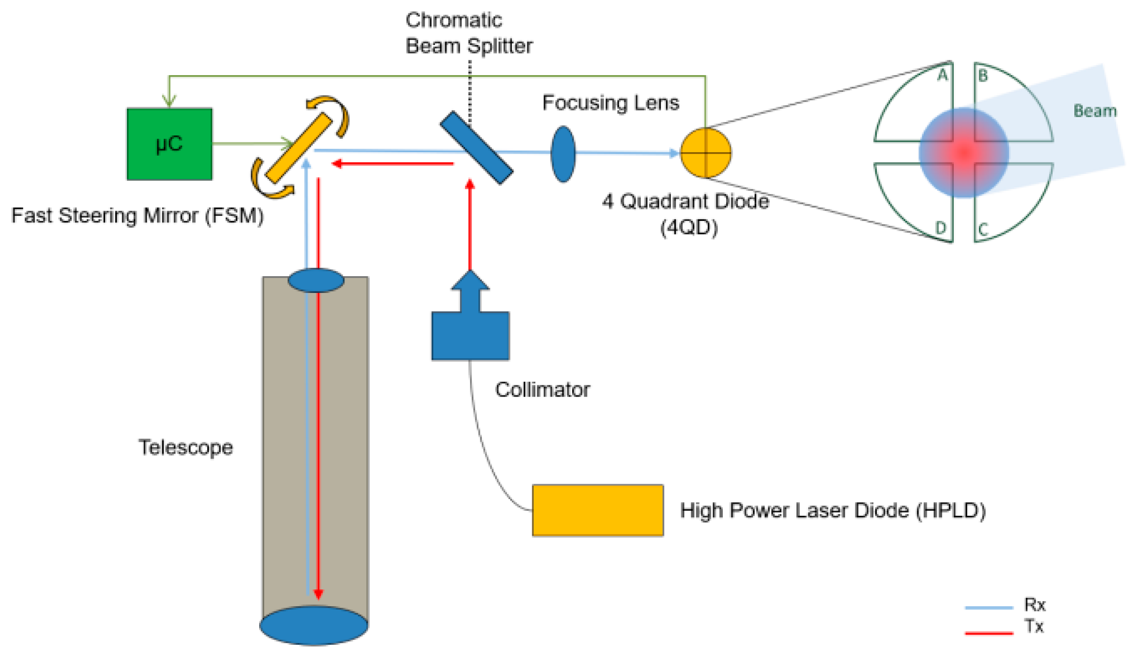
To summarize, mechanically actuated fine beam steering systems are the conventional solution for space applications and a common system (see Figure 1) in free-space optical communication terminals. This work focuses on fast-steering-mirror-based actuators. These actuators can be grouped into three main types based on their actuation source: electro-static force actuated, magnetic force actuated, and piezo-effect actuated.
In the following section, we discuss which FSM criteria are most important when considering their use for free-space optical communication in space applications.
2.1. Key Design Criteria of Fine Steering Systems for Optical Communication
2.1.1. Size, Weight, and Power (SWaP)
Power is one of the major design constraints of a space mission, especially for the nano- and micro-satellites due to their small solar panel size [16]. Even though free-space optical communication terminals have been shown to be more energy-efficient in transmitting data compared to radio transmitters [17], initial studies show that laser terminals could consume more than 45 W of power to drive laser diodes and electronics [18]. Currently, the power consumption of fast steering actuators varies between 200 mW and 5 W depending on the technology and the type of driving electronics. The size and weight of a fast steering actuator strongly depend on the size of the necessary mirrors, specific laser terminal requirements, and the optical layout. Having a smaller component size leads to a more compact laser terminal. In practice, the mass of FSMs varies from a few grams to a few kilograms depending on technology and mirror size.
2.1.2. Optical/Mechanical Steering Angles
The mechanical mirror steering angle refers to the angular displacement of a mirror from its nominal position. A large steering angle brings significant benefits for both the transmitter and receiver. It widens the field of view (FOV) of the tracking sensor, reducing platform pointing requirements during the acquisition phase. A greater telescope magnification factor leads to a higher tracking sensor resolution but reduces the FOV. The deflection angle of a steering mirror must be large enough to account for the magnification of the telescope. The higher the FSM tip-tilt angles are, the greater the satellite attitude errors that can be compensated for. Mechanical angles vary from ±0.04 to ±6.0 degrees. Having larger steering angles is usually beneficial, and it has been proposed to utilize a ±3.8 degree mirror deflection in the design of optical terminals for CubeSats [19].
2.1.3. Operational Bandwidth
The primary disturbances in optical communication for LEO satellites arise from attitude jitter resulting from attitude control loop errors, as well as from micro-vibrations that are caused by the motion of various mechanical components such as reaction wheels. The main task for a fast steering mirror in a free-space optical communication system is to eliminate these disturbances. The FSM bandwidth in this context pertains to how quickly a mirror can react to control signals and adjust its position. This responsiveness is influenced by factors like the needed precision for aiming the satellite’s beam, the amplitude and frequency distribution of satellite pointing errors, the satellite’s mass, and the distance to the terminal.
For example, in the case of deep space communication, which presents some challenging requirements, the bandwidth requirement of an FSM strongly depends on the satellite oscillations. These oscillations must not exceed 0.083 arcsec RMS motion from 1 Hz to 1 kHz during Mars–Earth communication events [20]. Usually, the necessary bandwidth for an FSM system varies from a few hundred Hz to more than 1 kHz. This requirement will depend on the specific satellite design and type of reaction wheel static and dynamic balance properties.
2.1.4. Pointing Accuracy
Pointing accuracy is an important measure, which, among others, depends on the resolution and repeatability of a fast steering mirror. Actuator repeatability is crucial in the open-loop mode, where there are no feedback signals available to assist in making precise adjustments to a beam. Having better repeatability in the open-loop mode also enables higher actuator bandwidth and greater accuracy when in the closed-loop mode. The resolution of an actuator refers to the smallest adjustment that an FSM could achieve. Resolution plays a role for long-distance optical communication where even very small angular deflection errors can translate into large movements of a laser beam spot, causing high link losses. The smaller the beam divergence, the higher the actuator resolution that is required. The accuracy of a fine-pointing system refers to its ability to precisely position the outgoing beam in the desired direction. Both repeatability and resolution are actuator specifications. From a system’s engineering standpoint, it is more meaningful to consider the overall system accuracy, which includes the FSM operating within a closed-loop sensor system along with its control algorithm. The current state-of-the-art fine beam pointing systems have pointing accuracies ranging from ±10 arcsec to ±0.1 arcsec [21,22].
2.1.5. Heat Dissipation from Actuators
For fine-pointing systems used in free-space optical communications, high heat dissipation can occur on reflective surfaces due to the high optical power of a laser beam. Different types of actuators have different heat-related problems. Smaller FSMs can experience thermal deformation issues caused by a high-power laser beam, while bigger actuators have a relatively high heat generation in the actuator itself, which can affect its performance. A more detailed review of thermal management for FSMs is provided in the sections describing each actuator.
2.1.6. Mirror Surface Quality
In an ideal case, mirrors or moving reflecting surfaces should change the laser beam direction without distorting its beam quality. The reflecting surface is characterized by the mirror’s flatness or radius of curvature, roughness, and mirror diameter. Maintaining the optimal values for these parameters is crucial to ensure low divergence and minimal distortions of the beam quality. Surface flatness and roughness are usually defined by root mean square (RMS) and peak-to-valley (PV) displacements and have to be as small as possible. For example, according to Saathof et al. (2018) [23], the mirror surface flatness for free-space optical communication applications should be less than 15 nm rms. COTS component manufacturers typically specify the radius of curvature (RoC) parameter in their specifications, with the majority of cases having a value greater than 5 m. Furthermore, small mirrors have smaller diameters, meaning a smaller heat dissipation area, which raises concerns about overheating and thermoelastic deformation problems. Another mirror parameter is its diameter. This requirement comes from the overall optical schematic architecture. In practice, the FSM’s diameter can usually be smaller in optical systems where the beam reaching the mirror surface is already collimated. A larger mirror diameter is useful when the mirror is positioned immediately after reflecting telescope mirror or refracting telescope lenses, where the beam is still in its focusing/diverging stage, or before the telescope, where the mirror diameter has to be greater than the telescope itself.
2.1.7. Optical Power Handling
For all transmitting laser terminals, more power allows for greater data rates, but it also means that optical components are exposed to higher thermal stresses. MEMS electro-statically actuated mechanisms have a major drawback when handling thermal loads. Optical power for LEO terminals varies from 200 mW to more than 10 W.
2.1.8. Cost
As a new space approach is becoming more and more predominant in the design of space systems, fast design cycles, low cost, and shorter lead time requirements play a role in the choice of a specific fine steering system [24]. In order to reduce R&D cost and time, it is preferable to use commercial off-the-shelf components (COTS) as much as possible. However, issues can arise when using a COTS component that has not been designed for space applications. Carrying out early testing of such components is very important.
3. Electrostatic MEMS Mirror
Micro Electro Mechanical Systems (MEMSs) with an integrated mirror have received considerable attention in terms of terrestrial and space applications because of their numerous advantages. A relatively low cost and ease of fabrication process make these commercial off-the-shelf (COTS) components attractive to the new space market. The acronym MEMS defines miniature devices or systems that combine electronic and mechanical components on a microscale. They are low in mass and size, which makes them perfectly suited for the high-priority SWaP methodology for satellites. These micro-mirrors are actuated by electrostatic force. There are two types of electrostatic actuators: comb-drive and parallel-plate [25]. The latter type can have two discrete ON and OFF states and is useful for applications that require a beam to be shifted into two different directions, e.g., as a micro-shutter in the James Web Space Telescope [26]. More widely used comb-drive actuators work in resonant and quasi-static modes [27]. Quasi-static or point-to-point modes enable the mirror to direct a laser beam toward any desired position with a specific velocity. On the other hand, resonant mode configurations restrict the mirror to execute solely sinusoidal continuous movement at a specific frequency, which is more applicable in LIDAR applications, where no pointing is required: the mirror is always in the scanning mode. Working in the resonant mode, the mirror can move in the range of a few kHz and achieve larger mechanical tilting angles; in both resonant and quasi-static modes, the moment of inertia and eigenfrequency play a crucial role in achieving this [28]. This is one of the reasons why MEMS mirror base structures are usually manufactured from silicon material with high specific stiffness. Silicon material with a Young’s modulus equal to ~160 GPa and a density of 2330 kg/m3 gives a good stiffness-to-density ratio [29]. Another reason is that widely developed silicon processing technology allows these devices to be manufactured at high precision and in large quantities, which makes them relatively cheap. This makes silicon the most popular choice for many MEMS devices, including electrostatic MEMS FSM.
3.1. MEMS Fast Steering Mirrors
3.1.1. Bandwidth and Mechanical Angle
A larger mirror mass or lack of actuating force are two major constraints limiting steering angle range and mirror bandwidth. Actuating forces, generated by electrostatic force, are relatively small compared to the other actuator types. The electrostatic force decreases with increasing electrode distance [30]. The inertia of a round mirror plate is proportional to the fourth power of its radius, and the ‘speed’ capability of the MEMS mirror is inversely proportional to the square of its radius [31]. Quasi-static mode FSM MEMS micromirrors have lower bandwidth compared to those working in resonant mode [32]. As an example, a quasi-static-mode FSM with a 4.2 mm diameter bonded mirror manufactured by Mirrorcle Technologies Inc. has the first resonant frequency of around 1.7 kHz, based on step response measurements, the working ‘speed’ is around 700 Hz at 0.45 deg deflection angles. The actual FSM mirror bandwidth depends on a few factors, but is mostly affected by the required tip-tilt angle range: smaller angle movements need less time to travel from one point to another and result in higher bandwidth. Resonant-type micromirrors can benefit from having a high amplification factor or Q-quality factor. However, for a quasi-static MEMS actuator, it is preferable to have greater damping to avoid undesirable overshoots and oscillations that could result from a higher quality factor [31]. MEMS devices with higher damping show greater chances of survivability aftershocks and vibrations [31]. Driving electronics plays one of the major roles in FSM bandwidth. Comb-drive technology allows for very low energy consumption: less than 1 mW for an actuator and 100 mW for driving electronics [31]. The FSM and the driver should reliably return to specified points. A crucial component of MEMS drivers is the digital-to-analog converter (DAC), which is sensitive to temperature fluctuations. Therefore, it is recommended to create a lookup table based on temperature ranges and incorporate a temperature sensor onboard this driver for these reasons [33].
3.1.2. Thermal Handling
Most MEMS micromirrors are bonded to the silicon structure. Usually, mirror bases are made from the same material, a thin 40–80 μm [34,35] thick layer of silicon, with just the top thin layer of about 100 nm deposited with metallic coatings such as aluminum, silver, or gold. The surface reflectivity varies from 95 to 98%, depending on the wavelength and coating. It means that some of the optical energy is absorbed and transferred as thermal energy. Comb-drive MEMS micromirrors are designed in a way that the whole mirror stands on thin torsion springs, so a solid thermal conduction path is not able to dissipate the constant heat load generated from optical power. Convection heat transfer is the most efficient way to dissipate heat in such cases. At a normal atmospheric ambient condition, convection can dissipate ~6 mW when the mirror is at 50 °C, and 20 mW when the mirror is at 100 °C [36]. Pereira et al. present a detailed analysis of the thermal issues for the 4.2 mm diameter MEMS FSM from Mirrorcle Technologies Inc. (https://www.mirrorcletech.com, accessed on 20 August 2023). Thermal simulations as well as experimental results have shown reduced thermal performance in vacuum conditions. Significant bending of the mirror structure can occur due to the difference in CTE between the substrate and surface coating material (gold). Even small changes in temperature can lead to relatively large thermomechanical deformations. Unfortunately, researchers have not provided mirror surface temperature as a comparable result at the same optical power in both vacuum and ambient environments. The mirror’ surface curvature peak-to-valley (PV) distance has been selected as a comparable measure. In the worst case scenario, at 0.5 W of optical power and ambient environment, the average PV is 46 nm. However, the same optical power in vacuum conditions results in an average PV of 266 nm. Pereira et al. (2020) [36] discovered two restrictions on the usage of Mirrorcle Technologies Inc. MEMS micromirrors for free-space optical communication. A deformed mirror surface has a negative impact on the link budget as a more diverging beam loses power on the ground and a distorted wavefront reduces signal quality. Reduced transmitted optical power limits the ability to communicate at long distances. This problem is well known in the automotive industry, where MEMS micromirrors are considered as one of the headlight components [35]. To overcome the high-power loading, which can reach up to several hundred watts on a relatively small mirror with very little thermal capacity, approximately 6 × 10⁻⁴ J/K, it may be possible to use dielectric coatings instead of metallic coatings. Dielectric coatings are able to reflect 99.9% of incoming optical power and thus reduce thermal load to the substrate. However, the main drawback of these coatings is that they exhibit high mechanical stress, which may have a negative impact on the reflective surface roughness [34]. To eliminate this problem, the mirror’s thickness should be increased, for example, to 700 μm, but this leads to the afore-mentioned problem of the increased moment of inertia, which limits the fast steering, and in some cases, results in six orders of magnitude lower bandwidth [37]. Since a considerable amount of heat can be dissipated via conduction through surrounding gas, it is advantageous to place the whole MEMS device into a sealed pack and reduce the distance from both mirror sides to ‘cool’ objects and thus give more efficient heat dissipation through conduction from gas molecules to colder structural casing [31]. In this case, the heat transfer is inversely proportional to the mirror’s distance from those ‘cool’ objects. Kasturi and his team demonstrated that mirror packing had nearly a quadruple improvement in thermal conductance, which led to an increased optical power of 5.5 W at 445 nm wavelength, compared to 4 W with a standard package [38].
3.1.3. Space Environment
The MEMS comb drive, torsion spring, and structure are the most fragile structural elements made from silicon and are susceptible to the shock and vibration forces induced by rocket launchers. Detailed MEMS micromirror characterizations are presented by [25]. The authors present shock and vibration simulations, and experimental results that are representative of the launch environment. Stiction, electrostatic charging, and outgassing issues are also discussed. At the end of the article, a performance comparison between the ground-based test and operation onboard the International Space Station is presented. The authors claim that the MEMS micromirror survived the launch and demonstrated nominal performance capabilities in the International Space Station. It is noteworthy that every case is different and strongly depends on the micromirror structural design, including mirror mass (size), satellite platform mass, and mounting orientation because, in the majority of cases, mirror piston movement, which refers to the displacement of a mirror surface perpendicular to its face, is critical for comb-drive micromirrors. Nevertheless, in most cases, a MEMS mirror is integrated into a free-space optical terminal which itself has several mechanical layers of mechanical interfaces further protecting from shock or vibration sources. In order to assess the behavior of the specific FSM device under shock and vibrations, test loads should be adjusted, or a flight-representative structural interface foreseen.
The harsh environment of space and rocket launch could be challenging for MEMS micromirrors. Dedicated research about the radiation impact on MEMS has been performed by Shea (2011) [39]. The author indicates that electrostatically operated MEMS devices typically degrade within the range of 10–100 krad, unless steps are taken to address overcharging dielectric layer issues in the device. Some of the commercially available MEMS devices were tested, with electrostatic being the most common device type (comb-drive) made of silicon material. However, these COTS devices failed when exposed to radiation doses ranging from 20 krad to 100 krad. It is worth noting that, in LEO orbit with 4 mm aluminum shielding or equivalent, the deposited dose per year is 1 krad of trapped protons. In the end, procedures to obtain more radiation-tolerant MEMS devices are recommended and the conclusion is drawn that radiation sensitivity would not be a limiting factor for MEMS usage in space. So far, there have been no issues arising from this factor in the electrostatic MEMS mirrors that have already been launched into orbit, as will be detailed below.
3.2. Flight Heritage of MEMS-Based Micro-Mirrors
3.2.1. CLICK Mission
The project called NODE (Nanosatellite Optical Downlink Experiment) presented a high-level overview of a free-space optical communication system. Since that publication, a lot of related articles and PhD theses have been published covering all the key elements of a free-space optical communication system development for a CubeSat platform. In 2018, the NODE project was renamed as CLICK (CubeSat Laser Infrared CrosslinK). The overall objective of the CLICK mission is to demonstrate free-space optical communication cross-links between two low-Earth-orbit (LEO) CubeSats. Later, it was decided to reduce the risk and move faster with several design iterations: as a result, the CLICK-A and CLICK-B/C missions appeared. The first mission, CLICK-A, with an objective to demonstrate the high-precision pointing performance of the fine steering mirror control system, was launched in July 2022. Since then, it has been known that the downlink laser is operational from the observation of the received signal on the optical ground station [40]. Throughout the seven-month mission duration, the optical terminal (see Figure 2) conducted six optical downlink experiments. Among these, three were considered partially successful, revealing that the MEMS FSM remained operational after launch. It was shown to be able to compensate successfully for the initial spacecraft blind pointing error of 0.487 deg and maintain an average RMS pointing error of 36 arcsec [40].
The second mission, CLICK-B/C, is scheduled for launch in late 2023 [41]. Both missions rely on electrostatic comb-drive MEMS fast steering mirrors manufactured by Mirrorcle Technologies, Inc. This choice was made after years of studying, analyzing, and characterizing this particular (COTS) component. The standard deviation of the residual inertial error of the attitude control system was simulated to be ~21 arcsec and 34.7 arcsec for X fit and Y fit, respectively, where the X-Y field angle was obtained from the inertial pointing error [42]. In order to overcome these errors, the closed-loop system should work at a sufficient bandwidth. Closed-loop bandwidth is limited by both detector and actuator bandwidth. Detector-operable bandwidth varies due to received signal power. According to Serra et al. (2019) [43], the detector onboard the CLICK satellite works at a 200 Hz refresh rate when it receives 100 nW of optical power on the Quad-cell from the ground beacon. In the early study phase, an FSM with a bandwidth of approximately 220 Hz, a diameter of 5 mm, and a mechanical deflection angle of ±3.8 degrees was selected for this mission [19]. Another important aspect of FSM performance is the ability to work in an open-loop mode where residual internal or misalignment errors are relevant. A test performed in article [33] found that, in the open-loop mode, the device achieves a 3σ repeatability of 12.4 arcsec. There were several impacts observed that affected the mirror alignment: physical deformation due to temperature shift, actuator zero position shift during power on, shift in sensitivity, the responsiveness of the device, and reduction in tip/tilt repeatability. In the worst case scenario, summing up all these factors, a total residual error of 78.4 arcsec in the open-loop mode can occur. The continuation of the work regarding these mirror tests and the closed-loop laser system is presented by Cierny (2017) [44]. In his Master’s thesis, the author presents a detailed testbed design and demonstrates that closed-loop control, using a MEMS mirror from Mirrorcle Inc., achieves a total error standard deviation of 2.2 arcsec when operating in closed-loop mode at 30 Hz. Some concerns and laser thermal loading issues are observed by Cierny et al. (2020) [45] during CLICK mission test procedures. During the TVAC test when a 200 mW communication laser beam continuously illuminates the mirror for 30 s, the peak-to-valley (PV) deformations of 266 nm were observed. According to the author, the impact on the link budget has little effect (0.02 dB change in transmit gain) and could be neglected in this scenario, but could cause issues with higher optical power. The mission status is discussed and presented by Serra et al. (2021) [46] who provided measured pointing error distribution, and showed the link margin performance for the ambient temperature for the vacuum pointing acquisition and tracking (PAT) test.
Figure 2.
Free-space optical flight terminal CLICK-A [46].
Figure 2.
Free-space optical flight terminal CLICK-A [46].

3.2.2. CubeLCT
Another free-space optical communication terminal for a CubeSat platform, CubeLCT, was developed by the Germany Aerospace Center together with Company Tesat. The optical transceiver payload was integrated into the 3U CubeSat platform and launched during a PIXL-1 mission at the beginning of 2021. The COTS MEMS FSM solution, driven by electrostatic capacity combs, was used for this terminal Rödiger et al. (2022) [15]. General information about the laser terminal (see Figure 3) is provided by Rödiger et al. (2020) [47] with some pointing, acquisition, and tracking data: focal plane field of view ±1 deg, closed-loop bandwidth—200 Hz, and fine-pointing detection is performed with a quadrant detector. According to the author, the terminal is fully operational, and there are no degradations, irritations, or other issues related to the fast steering mirror and the overall optical terminal. However, the satellites’ star tracker and magnetometers do not perform reliably [48]. Due to these reasons, it cannot ensure stable and accurate coarse pointing within ±1 degree, which is necessary for a stable link. This is another example of using the advantages of COTS components by integrating MEMS electrostatically driven beam steering devices into small laser terminals.
3.2.3. DeMi Mission
MEMS technology could be adopted for a deformable mirror solution. A deformable mirror works by using an array of actuators or segments to change the curvature of the mirror and correct for optical aberrations [49], while a fast steering mirror works by using a displacement actuator and a pair of motion-tracking sensors to tilt the mirror and change the angle of the reflected beam. The deformable mirror’s segment moves precisely up or down, changing the reflected beam’s phase and wavefront. In order to actuate those segments, the controlled electrostatic force is created following the same actuating principle as in the afore-discussed FSM. Although there are differences in the application compared to optical communication, the main challenges of the technology are similar. In 2020, one of the deformable mirrors driven by electrostatic force was tested on a CubeSat satellite. The detailed in-orbit results are presented by Vlahakis (2022) [50]. According to the authors, the DeMi mission successfully raised the technology readiness level (TRL) from 5 (component and/or breadboard validation in relevant environment) to 9 (“flight proven” during a successful mission). The COTS deformable mirror manufactured by (BMC) Boston Micromachines Corporation (Cambridge, MA, USA) survived harsh launch loads. No evidence of stuck, unresponsive, or erratic actuators’ operation was observed. Unfortunately, not all measurements of 140 actuators were collected. Major issues occurred while downloading the data from satellite to the ground and many files were corrupted or missing, but an average of 16 actuator measurements were analyzed. Individual actuators’ repeatability of deflection was measured in orbit and found to be within the 2 to 13 nm range.
A summary of technical specifications is provided in Table 1. MEMS fast steering mirrors from three companies are presented. There are several companies manufacturing MEMS micro-mirrors in the market, including Hamamatsu Corp. (Hamamatsu City, Japan), Sercalo Microtechnology Itd. (Neuchâtel, Switzerland), and Thorlabs, Inc. (Newton, New Jersey, USA) However, due to the lack of published papers, it is challenging to make a proper comparison of their product performances.
4. Lorentz-Force-Based Actuators
This section presents FSMs where the main actuation principle is based on Lorentz force. It describes the force experienced by a charged particle (such as an electron) when it moves through an electric field and a magnetic field. Compared to other types of actuators, it can create larger actuation strokes that are converted to larger tip-tilt mirror angles. This type of actuation gives sufficient force to drive large mirrors up to 80 mm in diameter [51]. This gives it an advantage over mirrors with a relatively large thermal capacity. Lorentz-force-based actuators fall into two categories: voice-coil- and hybrid reluctance (HR)-based technologies. One of the major differences between these two actuators is that a permanent magnet of an HR actuator provides a magnetic biasing field, which can make these actuators 10 times more efficient in power consumption than voice coil actuators [52]. The following sub-sections analyze state-of-the-art research related to magnetic-based fast steering systems, which were selected based on their relevance for free-space optical communication in space. One of the most important advantages of these actuators is their capability to achieve mechanical rotation angles of more than ±2 degrees.
4.1. Voice Coil Fast Steering Mirror
Voice coil technology is well established and was originally introduced in galvanometer mechanisms in terrestrial use in the early 1800s. Instead of using it as a solenoid, a mirror can be attached, creating a laser-beam-pointing mechanism. The key requirements of fast steering mirrors for free-space optical communication as well as the main development stages, including the testing and validation of wavefront error (WFE) and pointing accuracy, are presented by Langenbach and Schmid (2005) [53]. The fast steering mirror designed by Langenbach and Schmid has four voice coils and a mirror attached on top. The tip-tilt motion of the mirror is created by the linear extension and retraction of the actuator. This technology was commercialized by TESAT and enabled a publicly demonstrated gigabit laser-based communication between the LEO satellite Sentinel-1A and the GEO satellite Alphasat in 2014 [54]. In 2019, the laser communication terminal with an integrated voice coil beam steering mechanism made its 20.000th successful optical link and since then its optical payload is still operational [55]. Some of the TESAT FSM specifications are presented in Table 2 together with voice coil actuators from other providers.
A voice coil mechanism for inter-satellite beam steering is proposed by Coppoolse et al. (2003) [21]. The FSM is capable of a 1 kHz bandwidth with an integrated feed-back sensor in the same mechanism. The FSM by Coppoolse et al. (2003) [21] has a power consumption of 2.5 W, and a housing of 55 mm in diameter and 27.5 mm in length. The assembly had a mounted mirror 28 mm in diameter, flexible mirror suspension, actuators, sensors, and a system controller. The authors demonstrated how a pre-tension device avoids numerous stable angular positions in a flexible mirror suspension and provides high stiffness for translational movements. The assembly was verified and tested. The noise observed at the center position of the mirror was minimal, measuring below 0.04 arcsec, and it increased as the deflection angle increased. At 928.2 arcsec angle offset, ±0.06 arcsec noise was measured. The absolute linearity error was measured, and it was found that a linearity error of ±2% met the requirements within the nominal ±0.4 deg displacement range. Open and closed loop plant response was measured.
A voice coil actuated steerable mirror assembly for CubeSats is presented by Applied Technology Associates (ATA) [56]. Similar actuation principles and mirror assemblies were used as in the previously presented solutions of Tesat and Coppoolse et al. The FSM design was selected with the integrated feedback sensor Kaman KD5100, which was calibrated for non-linearity errors due to temperature changes. The authors achieved open loop and closed loop bandwidths of 1500 Hz and 2500 Hz, respectively, and an accuracy of ±1 arcsec. Thermal cycling and random vibration showed that the central flexure passed the test with a load of >25 G for three minutes on each axis without any breakage. Post-test mirror accuracy results have shown a difference of 2 arcsec in measured errors between the two axes, but according to the author, it is tolerable for a typical laser transmitter with 5–10 cm diameter aperture. Some of the performance specs of ATA’s FSM mirror are presented in Table 2 for comparison.
4.2. Magnetic Reluctance Fast Steering Mirror
Another type of Lorenz-force-based fast steering actuator is based on magnetic reluctance principles. Magnetic reluctance actuators are also known as hybrid reluctance (HR) actuators, where the term ‘hybrid’ means two different sources of magnetic flux: coils and permanent magnets. The addition of permanent magnets decreases the non-linearity of an actuator. In comparison to the usual voice coil actuator, magnetic reluctance actuators have higher efficiency as measured by the proportion of force generated per unit volume and the ratio of force per unit of energy input [57]. A selection of these actuators is reviewed and compared in this sub-section (see Table 3).
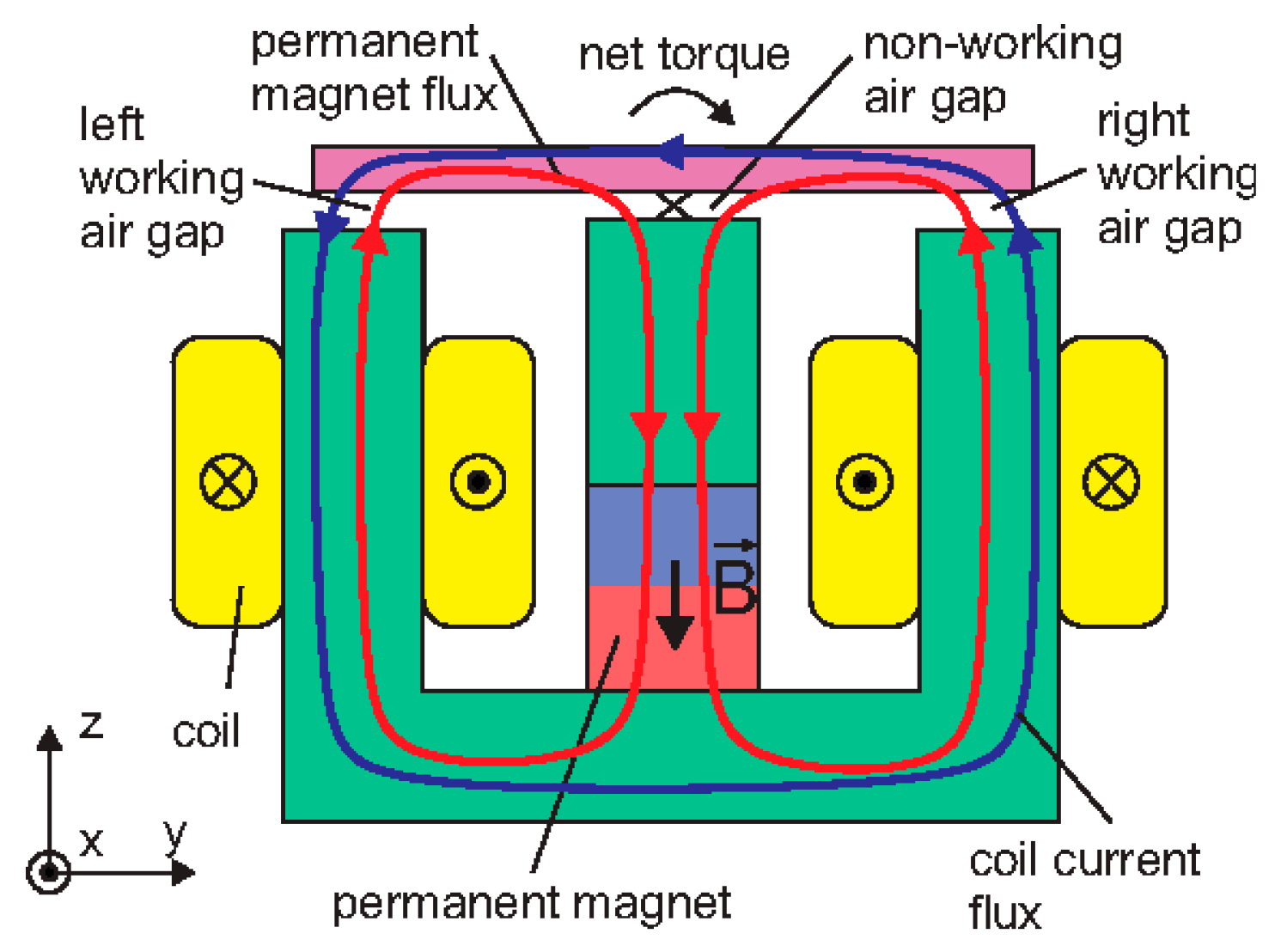
The working principle of a magnetic reluctance actuator is explained by Csencsics et al. (2017) [58] and shown in Figure 4. The permanent magnet’s biasing flux (red) is split between the outer yoke parts. The steering flux (blue) created by the coil current enhances or diminishes the biasing flux in the right and left air gaps, resulting in a clockwise or counter-clockwise torque on the ferromagnetic mover (colored in magenta).
A fine steering mirror project was initiated by the Netherlands Organisation for Applied Scientific Research (TNO). One of the essential components of this project is the HR actuator, which is able to achieve a very small power consumption of about 0.14 W per coil [59]. The main focus was on performance validation from the bandwidth and pointing jitter perspectives, as well as frequency response. The controller design is based on a low-pass PID with a feedback sensor running at 20 kHz. The authors did not provide any accuracy measurements but reported an angular jitter error of less than 0.3 arcsec rms, which depends on feedback performance and external disturbances. Angular jitter, also known as noise, refers to rapid fluctuations or variations in the angular position, but the actual resolution was not provided in the results. Mirror deformations were modeled due to the absorption of the optical power, which exceeded more than 10 W [57]. The Finite Element Analysis (FEA) result revealed a shape inaccuracy of 3 nm RMS at 200 mW absorption, which is significantly less than the overall target budget of 60 nm rms at 1550 nm. This FSM is planned to be integrated into a range of commercial laser terminals developed by TNO, such as UltraAir, HemiCAT, SmallCAT, and LEOCAT [60,61]. The SmallCAT terminal was integrated and launched on 15 April 2023 as part of the NorSat Technology Demonstrator mission.
Recently, Cedrant Technologies have introduced magnetic-reluctance-based solutions [62]. The low-power, high-stroke, high-bandwidth fast steering mirror with a magnetic reluctant actuator was presented by Claeyssen et al. (2020) [63]. To achieve its full stroke ±2.0 degrees of mechanical range, the fast steering mirror employs four linear Moving Iron Controllable Actuators (MICAs). Because of these actuators, the FSM can achieve a bandwidth of 250 Hz. The states are 3.75 W per actuator, running with a sine wave at 20 Hz at full stroke amplitude. Based on theoretical and experimental natural frequency tests, the authors found four fundamental modes: tilt, 110 Hz, normal, 160 Hz, torsion, 600 Hz, and share, and 860 Hz. During thermal analysis under 240 W peak electrical power load and 200 Hz driving frequency, it was found that maximum coil temperature can reach 97 °C, whereas moving parts do not exceed 42 °C. In these severe conditions, operating at a bandwidth twice as high as the eigenfrequency of the components, which is 110 Hz, resulted in increased current loads [64]. It was shown that operation at this level could be sustained for 10 min at ambient temperature. The authors did not provide information about the FSM’s repeatability. Resolution capabilities were mentioned in the range from 0.4 to 1 arcsec.

Table 3.
Main requirements/specifications of fast steering mirror with magnetic reluctance design [59,65].
| TNO FSM | Cedrat Technologies M-FSM | Technische Universität Wien by E. Csencsics | |
|---|---|---|---|
| Housing dimensions, diameter ± height, H in mm | Ø27 × H30 | Ø62 × H56 | Ø32 × H30 |
| Mass, (g) | 61 | 400 | n.d. |
| Power consumption (per actuator), (W) | 0.14 | 3.75 | 1.5 |
| Total angle range (mechanical), (deg) | ±2.0 | ±2.0 | ±3.0 |
| FSM accuracy, (arcsec) | n.d. | n.d. | 10.8–111.6 |
| Optical pointing jitter, (arcsec) | <0.2 | n.d. | n.d. |
| Open—(O) or closed—(C) Loop Bandwidth, (Hz) | (C) 1700 | (O) 250 | (C) 1500 |
| Mirror WFE rms | λ/60 | n.d. | n.d. |
A hybrid reluctance (HR) fast steering mirror was designed and tested by Csencsics et al. (2019) [65]. Its large mover diameter of 20 mm allows for mirror integration up to the same diameter. The mechanical suspension system guarantees that structural modes are greater than the natural frequency of a rocket launcher and is a critical component for these types of HR actuators. As a result, the frequency response of both system axes is of second order, with a resonance frequency of 400 Hz. Tracking performance was conducted on various trajectories such as the Lissajous trajectory, raster trajectory, and step response. The first, Lissajous trajectory was performed with fundamental frequencies of 40 Hz and 30 Hz and with a scan amplitude of 2.5 degrees. For each sampled point along the trajectory, the areal rms tracking error is calculated, yielding 5.1 arcsec. For the pre-defined raster trajectory, the tracking control loop speed was 30 Hz for the faster axis and 0.5 Hz for the slower axis, with a scan amplitude of 3°. Unfortunately, the system has current limitations, so, higher fundamental frequencies of the signal that has a triangular shape, called a triangular reference signal, can distort the output position signal. Tracking rms and peak-to-valley errors were found to be 111.4 arcsec and 660 arcsec, respectively. When a 14 arcsec step was applied, the system angular resolution or rms positioning uncertainty was found to be 7 arcsec. The suggested system design has a notable advantage with its relatively large mechanical angle of ±3 degrees.
4.3. Electromagnetically Driven MEMS FSM
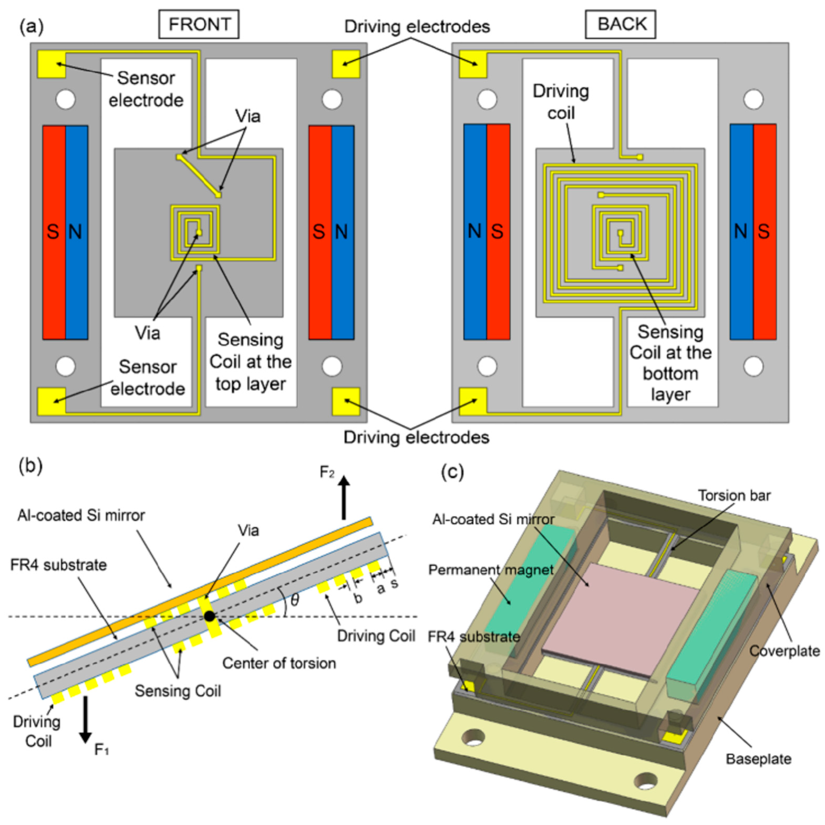
In electromagnetic MEMS FSM devices, a magnetic field is used to actuate the mirror. Figure 5 shows a detailed view of a design presented by Lei et al. (2018) [66]. The package size is similar to electrostatically driven MEMS FSMs. One advantage of using electromagnetically versus electrostatically driven MEMS FSMs is that they can provide a higher actuation force, which can be useful in applications that require large mirror deflections. Additionally, the use of magnetic actuation can provide better stability and lower noise, which is important in optical communication applications. However, there are also some challenges associated with the use of electromagnetically driven MEMS FSM devices. For example, the magnetic field emitted by an actuator can interfere with other magnetic components on a satellite, such as sensors or scientific instruments. The performance of magnetically actuated MEMS FSM systems is hard to evaluate due to a lack of publications, and it raises significant concerns regarding thermal management. Moreover, the fabrication process for MEMS devices incorporating magnetic components can be more intricate and costly compared to those using only electrostatic actuation. Additionally, the materials required for electrostatic MEMS devices are often more easily accessible and cost-effective. There are a few commercially available tip-tilt FSMs in the market, such as the ones provided by Hamamatsu, Sercalo, and Texas Instruments (see Table 4). However, to the best of the authors’ knowledge, there are no publications detailing their use for free-space optical communication.
5. Piezo-Effect-Driven Fast Steering Actuators
Actuators based on the piezoelectric effect are an established technology for space applications. They have been used on many space missions such as ROSETTA [67], Semi-Conductor Inter Satellite Link Experiment (SILEX) [68], and Atmospheric Dynamics Mission-Aeolus (ADM-Aeolus) [69]. More piezo-driven actuators are presented by Allegranza et al. (2014) [70]. Piezoelectric actuators are typically used for such space applications as scanning, precise pointing, laser ranging, maintaining propulsion control mechanisms, and point ahead angle mechanisms. Most conventional FSM systems based on the piezoelectric effect are high in accuracy (micro-rad range), bandwidth (>1 kHz), and range, and do not emit interfering magnetic fields. However, there are some drawbacks, such as limited angular motion range [1], the hysteresis effect, and the need for high-voltage and high-power consumption driving controllers [71].
5.1. Piezo-Stack Stage
One of the most popular design concepts in this category of actuators is FSMs driven by so-called piezo-stack stages. The tip-tilt motion is created by a stack of ceramic piezo-actuators placed in the mechanical amplification stage. By applying a voltage to the ceramic piezo-stack, it produces small μm ‘berthing’ movements. Those movements are amplified by a mechanical amplification mechanism [72], which can amplify input movements by 40 times. A piezo actuator with a diamond-type micro-displacement amplifier (DMDA) mechanism is presented in Figure 6 [73]. One of the challenges in the design of these actuators is to achieve a high natural frequency while keeping a relatively large amplification factor [74]. Cedrant Technologies have developed space-qualified versions of piezo-ceramic tip-tilt actuators that are available commercially [75].
These types of actuators are more feasible for deep-space optical communication purposes due to their tiny angular range movements of ±0.14 degrees [22]. In some laser communication terminals, there is a point-ahead mirror that adjusts the outgoing beam direction slightly ahead of its intended target to compensate for the time delay it takes for the laser signal to travel to the receiver [76]. For such a mechanism, a piezo-stack-based beam steering mechanism is planned to be used in the PSYCHE mission in late 2023 [77].
A Miniature Pointing and Stabilization Subsystem (MPSS) driven by piezo actuators has been designed by the Italian company Stellar as part of their CubeSat free-space optical communication system called LaserCube [78]. LaserCube (see Figure 7) was designed for a full-duplex operation, where a transmitter and receiver would work simultaneously for inter-satellite, downlink, and uplink communications. The coarse stage of ±10 deg FOV and 10.3 arcsec rms accuracy was designed to compensate for slow movements and low bandwidth disturbances. It employed two linear walking piezo-motors with <1 nm resolution and optical encoders. The second tip-tilt piezo stage with ±144.4 arcsec FOV and less than 2 arcsec rms accuracy was used to eliminate higher bandwidth errors [76]. Based on the analysis of the tracking error budget, which identifies error contributors like linear motor encoders, optical sensors, attitude jitter, and sinusoidal reference (in the downlink scenario), the total error in the downlink scenario was calculated to be 0.9 arcsec for elevation and 0.8 arcsec for azimuth axes, respectively. For the tracking accuracy test, sinusoidal reference trajectories were introduced with low frequencies of 0.025 Hz, 0.05 Hz, 0.1 Hz, 0.2 Hz, and 0.5 Hz, and a trajectory amplitude equal to 361 arcsec. The tracking accuracy was less than 1.4 arcsec in the worst case where 0.5 Hz trajectory was imposed. A similar method was used to simulate jitter disturbances on a 2U CubeSat platform. Imposed disturbances were simulated as sinusoidal waves with frequencies ranging from 0.01 to 10 Hz and corresponding amplitudes decreasing from 3506 to 10.3 arcsec. Jitter-induced pointing errors of less than 2 arcsec were reported. Relatively low disturbance frequencies were chosen, where order-of-magnitude or greater frequencies are common for an ADCS system [79]. The coarse pointing system consumed up to 5 W of electric power and weighed 280 g [80]. LaserCube was successfully developed and launched into space by the Stellar Project company with the ‘LaserComm Pills’ series in the summer of 2022. Unfortunately, no information about the mission results has been published yet.
5.2. Piezoelectric MEMS Fast Steering Mirrors
Although the use of piezo-stack stages is common for fine beam steering mechanisms, meeting size, weight and power requirements for small satellite platforms with these actuators is challenging. For that purpose, MEMS-based piezo actuators with an integrated gimbaled mirror for beam adjustment were suggested [82,83,84,85,86,87].
In the case of piezo-electric MEMS, thin layers of piezo film material serve as stretching-bending mechanisms in quasi-static mode. These actuators typically have low power consumption, low settling time, and large scan angles [83]. To the best of the authors’ knowledge, there are no public projects where piezo-film actuation is used for optical communication in space applications. This is a relatively new and not well-tested technology. The technology’s key advantage over other MEMS steering mirrors is the ability to utilize larger mirror apertures due to its larger actuating force. Boni et al. have designed, manufactured, and tested a beam steering actuator assembly for a 4 mm × 3 mm rectangular mirror and an integrated diffused piezoresistive sensor for feedback control [84]. The main structure was made of silicon, while the piezoelectrical film was deposited on it, and acted as an actuator. The cross-section view in Figure 8 shows two sandwich slides to understand MEMS mirror design with bending piezo-film actuators. During experimental modal analysis, torsional rotation was discovered as the first mode at 570 Hz. MEMS reliability tests were performed under 0–40 V cycles for 168 h. Even when working in an open loop without feedback, the opening angle remained constant, and there were no mechanical or electrical concerns. Shock tests have been performed according to MIL-STD-883E specification. The actuator survived 1500 G load with 0.5 ms pulse width but failed at 3000 G load and 0.3 ms pulse length at the torsional spring location. The work of Boni et al. has demonstrated the feasibility of small-size piezo-driven MEMS actuators with relatively large deflection angles of ±9 deg. In quasi-static actuation mode, the refresh rate is limited to 120 Hz.
Although PZT is the most common piezoelectric material used for this application, due to its characteristic non-linearity, researchers have tried to find better-suited materials, such as non-ferroelectric AlScN and AlN piezoelectric materials. A detailed comparison of PZT, AlN, and AlScN was performed by Gu-Stoppel et al. (2020) [85]. PZT material has up to a 20-times-greater piezoelectric coefficient (e31): a parameter that represents a material’s piezoelectric effect, meaning that the same volume of material is able to create 20 times more force compared to AlN- or AlScN-based piezoceramics. However, AlN or AlScN materials do not show non-linearity problems, which is one of the major issues for PZT. A recent advancement in the use of these relatively new piezoelectric materials for FSM applications has been made by Gu-Stoppel et al. (2021) [88]. Gu-Stoppel et al. simulated, manufactured, and tested three samples of actuators made of AlN material with different sizes of integrated mirrors of 2 mm, 5 mm, and 10 mm. They measured the eigenfrequency values for the 5 mm mirror combination and found that the first and second modes for the tilting axis were 231 Hz and 263 Hz, respectively. Mechanical tilting angles of 5 deg at 80 V drive voltage were achieved in one direction. Step response graphs with measured decay time τ = 80 ms and a calculated Q-factor of 50 were also provided, which is a measure of the efficiency of a system. It is used to assess how well a system can store or transfer energy before it is lost or dissipated. Studies on quality factor impact on MEMS mirrors were overviewed by Milanović et al. (2017) [31]. For driving a quasi-static MEMS mirror, the large quality factor results in undesirable overshoots and oscillations. Rapid control algorithms improved extreme oscillations of this mirror structure by controlling the signal slopes of LIDAR scanning, but further investigation is necessary for working in quasi-static mode [89].
Ongoing research is focusing on the utilization of piezoelectric MEMS with integrated mirrors, employing PZT or similar film material actuators. However, instead of operating in the quasi-static mode, these developments are exploring the use in resonant-type operation. These mirrors are also known as scanners [90]. For instance, Meinel et al. demonstrated an example that can achieve larger mechanical deflection angles of up to ±30 degrees with resonant excitation at 50 V, providing 13,145 Hz oscillation. On the other hand, resonant-type actuators can also work in the quasi-static mode but with lower efficiency and smaller deflection angles of 1.5 deg at 100 V and 30 Hz. While these scanning mirrors find more applications in LIDAR or medical settings [86], they are not suitable for optical communication due to their low bandwidth in quasi-static mode. Zhang et al. (2015) [87] have suggested MEMS mirrors working on a principle of bimorphing plate, where symmetric Cu/W/Cu thin film acts as an actuator. Due to the nature of electrothermal actuation, these mirrors generate heat during operation. The thermal effects can cause thermal drift, which might impact the stability and accuracy of the beam steering, requiring additional thermal management measures that might be complicated for a space application.
5.3. X-Y Piezo Stage
In some cases, a different kinematic approach could be selected instead of using a tip-tilt mirror as a reflecting surface. One can steer the outgoing beam direction by laterally translating the positioning of the incoming beam in the x and y directions. The emitting source can be positioned in an x-y direction before the telescope or lens, causing the beam to change its angular position after the telescope. The idea is shown in Figure 9 [91]. The X-Y translational stage is often operated by piezo-stack actuators, similar to those employed in the tip-tilt piezo stage version detailed in Section 5.1. Joints and translational levers, which are required for rotational movement in tip-tilt actuators, could be avoided in translational actuators. This technology, like a piezo-stack, is well established and has already been tested in space, e.g., during the ASTERIA mission, it was used for the alignment of the CMOS detector [92]. The ASTERIA mission’s goal was to scan and perform photometry on nearby stars in order to locate transiting exoplanets. A 6U CubeSat was successfully launched from the ISS, and the collected data showed that the positioning mechanism was able to deliver 0.5 arcsec RMS pointing accuracy over 20 min of system operation.
Another 3U nanosatellite mission where the X-Y piezo translational stage was used was called the PicSat mission and was launched in 2018. The primary goal of the mission was to continuously monitor the giant planet β Pictoris’s brightness. The PicSat mission was designed on translational movements of the fiber tip, which coupled light into single-mode fiber and measured the planet’s brightness. Although this design could be adapted for free-space optical communication, the biggest drawback is a relatively small output angle of ±59.8 arcsec, limited by small ±250 μm translational movements before the telescope [91]. Unfortunately, the mission was not successful as the satellite went silent after the launch. Nevertheless, the simulation results demonstrated that a lateral position of a single-mode fiber can be adjusted at 1 kHz speed. The preliminary study indicated that the two-stage system, consisting of the ADCS and a loop-controlled piezo actuator, had the potential to achieve a pointing precision of 1 arcsec.
6. FSM Summary
Selecting the right type of beam steering actuator that is capable of ensuring the mechanical pointing of the laser at the required accuracy, speed, and reliability is not an easy task. This work suggests that different types of actuators have certain advantages and disadvantages, requiring a detailed trade analysis. The discussed FSM types are summarized in Table 5. This is a qualitative comparison based on the individual publications reviewed in this article and the authors’ knowledge. The main criterion selected is the relevance to free-space optical communication applications.
7. Summary
The key design criteria for fine steering systems in optical communication have been identified. Optical and mechanical steering angles depend on the accuracy of a coarse pointing stage and optical design, ranging from ±0.04 to ±5.0 degrees in mechanical rotation. Repeatability, resolution, and accuracy play a crucial role, with typical accuracy requirements varying between ±0.1 arcsec and ±10.3 arcsec. The operational bandwidth of FSMs typically falls within the range of a few hundred Hz to 1 kHz and depends on actuator power, mirror mass/size, and deflection angles. Mirror surface parameters significantly impact the beam quality and must remain stable during laser illumination, withstanding optical powers ranging from 200 mW to over 10 W. Additionally, the size, weight, and power (SWaP) criteria play a vital role in the cost-effectiveness and efficiency of the system, especially in the context of space applications. An analysis of laser beam steering technology has identified three main actuation types: electrostatic force actuated, magnetic force actuated, and piezo-effect actuated. MEMS FSM actuators have demonstrated high technology readiness and cost-effectiveness, offering advantages such as low power consumption, small weight, and sufficient bandwidth. MEMS electrostatic mirror actuators have been successful in achieving 200 mW of optical power in vacuum conditions and have already gained flight heritage. The voice-coil-, magnetic-reluctance-, and other magnetism-based actuators allow for achieving mechanical angles larger than ±2 degrees in the case of larger mirrors, 10 mm and more, with bandwidths exceeding 1 kHz. The voice coil FSM is an established and reliable technology, already employed on commercial laser communication terminals. However, it faces challenges related to heat generation under vacuum conditions due to Lorentz-force operation, as well as complexities stemming from temperature fluctuations and magnetic flux control. The magnetic reluctance of the FSM exhibits the potential for better energy efficiency, with power consumption as low as 0.14 W per actuator, and offers greater mechanical deflection angles up to ±6 degrees. Nonetheless, it requires careful consideration due to the presence of permanent magnets, which can in certain cases lead to compatibility issues. Piezoelectric MEMS actuators are promising for space applications due to their small power consumption and compact size. Although they possess the potential for powerful actuation, leading to higher eigenfrequency values and bandwidths compared to electrostatic MEMS actuators, they are still in the early stages of research and development. Piezo-stack stage actuation is an established technology used in various space missions, capable of achieving high resolution (<1 nm) and kilohertz bandwidths. However, they are limited in travel distance, typically in the range of tens of micrometers, and involve complex mechanical amplification mechanisms, resulting in only ±144.4 arcsec of deflection angles. Additionally, brittle piezoceramics impose high requirements for shock and vibration isolation on satellite platforms, although they can tolerate higher heat dissipation. The limited options for space-qualified fast steering mirrors (FSMs) still remain one of the bottlenecks preventing the widespread adoption of optical communication in space. However, addressing this issue will pave the way for improved performance and enhanced reliability in space-based free-space optical communication.
Funding
This article was fully funded by the VilniusTECH Antanas Gustaitis Aviation Institute within the framework of the PhD program.
Acknowledgments
We extend our sincere gratitude to Benjamin Roediger from DLR for providing valuable clarifications regarding the CubeLCT project via email.
Conflicts of Interest
The authors declare no conflict of interest.
References
- Muhire, D.; Stepanova, D.; Santra, S.; Baranwal, P.; Romero, M.; Amrutkar, R.; Bonnart, S.; Jha, D.; Zucherman, A. Optical communications for small satellites: A review of pointing strategies & requirements optimization. In Proceedings of the International Astronautical Congress, IAC, Online, 12–14 October 2020. [Google Scholar]
- Kaymak, Y.; Rojas-Cessa, R.; Feng, J.; Ansari, N.; Zhou, M.C.; Zhang, T. A Survey on Acquisition, Tracking, and Pointing Mechanisms for Mobile Free-Space Optical Communications. IEEE Commun. Surv. Tutorials 2018, 20, 1104–1123. [Google Scholar] [CrossRef]
- Heine, F.; Kämpfner, H.; Lange, R.; Czichy, R.; Meyer, R.; Lutzer, M. Optical inter-satellite communication operational. In Proceedings of the IEEE Military Communications Conference MILCOM, San Jose, CA, USA, 31 October–3 November 2010; pp. 1583–1587. [Google Scholar] [CrossRef]
- Liao, S.-K.; Cai, W.-Q.; Liu, W.-Y.; Zhang, L.; Li, Y.; Ren, J.-G.; Yin, J.; Shen, Q.; Cao, Y.; Li, Z.-P.; et al. Satellite-to-ground quantum key distribution. Nature 2017, 549, 43–47. [Google Scholar] [CrossRef] [PubMed]
- Kaushal, H.; Kaddoum, G. Optical Communication in Space: Challenges and Mitigation Techniques. IEEE Commun. Surv. Tutorials 2017, 19, 57–96. [Google Scholar] [CrossRef]
- Tian, J.; Tingbiao, G.; Nan, H.; Ji, D.; Qiangsheng, H.; Xiaojian, H.; Chao, F.; Yuan, W.; Tianyi, Z.; Junping, Z.; et al. Wide-Field-of-View Modulating Retro-Reflector System Based on a Telecentric Lens for High-Speed Free-Space Optical Communication. IEEE Photonics J. 2023, 15, 7303908. [Google Scholar] [CrossRef]
- Stockley, J.; Serati, S. Advances in liquid crystal beam steering. In Proceedings of the Free-Space Laser Communications IV, Denver, CO, USA, 2–4 August 2004; Volume 5550, p. 32. [Google Scholar] [CrossRef]
- Kackera, S.; Cahoy, K. Optical Performance of Commercial Liquid Lens Assemblies in Microgravity. TechRxiv 2023. [Google Scholar] [CrossRef]
- Goorjian, P.M. A new laser beam pointing method using laser arrays. In Proceedings of the Free-Space Laser Communications XXXI, San Francisco, CA, USA, 2–7 February 2019; Volume 10910. [Google Scholar] [CrossRef]
- Miller, S.A.; Chang, Y.-C.; Phare, C.T.; Shin, M.C.; Zadka, M.; Roberts, S.P.; Stern, B.; Ji, X.; Mohanty, A.; Gordillo, O.A.J.; et al. Large-scale optical phased array using a low-power multi-pass silicon photonic platform. Optica 2020, 7, 3–6. [Google Scholar] [CrossRef]
- Serati, S.; Stockley, J. Advanced liquid crystal on silicon optical phased arrays. IEEE Aerosp. Conf. Proc. 2002, 3, 1395–1402. [Google Scholar] [CrossRef]
- Pan, G.; Xu, C.; Xie, Y.; Dong, Y.; Wang, Q.; Deng, J.; Sun, J.; Chen, H. Ultra-compact electrically controlled beam steering chip based on coherently coupled VCSEL array directly integrated with optical phased array. Opt. Express 2019, 27, 13910–13922. [Google Scholar] [CrossRef]
- Goorjian, P.M. Free-Space Optical Communication for CubeSats in Low Lunar Orbit (LLO). In Proceedings of the Free-Space Laser Communications XXXII, San Francisco, CA, USA, 1–6 February 2020; Volume 11272, pp. 2–6. [Google Scholar]
- Goorjian, P. Space Optical Communications Using Laser Beams. US Patent 9,774,395 B1, 26 September 2017. [Google Scholar]
- Rödiger, B.; Rüddenklau, R.; Schmidt, C.; Lehmann, M. Acquisition concept for optical inter-satellite communication terminals on cubesats. In Proceedings of the International Conference: Oberpfaffenhofen, Vilamoura, Portugal, 19 May 2022; no. 1. pp. 1–12. Available online: https://elib.dlr.de/187119/ (accessed on 6 August 2023).
- Gorev, V.N.; Prokopiev, V.Y.; Prokopiev, Y.M.; Sinitsina, L.D.; Sidorchuk, A.A. Calculating electric power generated by 3U CubeSat’s photoconverters depending on the orbit and orientation parameters. IOP Conf. Ser. Mater. Sci. Eng. 2019, 537, 022079. [Google Scholar] [CrossRef]
- Toyoshima, M. Recent Trends in Space Laser Communications for Small Satellites and Constellations. J. Light. Technol. 2020, 39, 693–699. [Google Scholar] [CrossRef]
- Baister, G.; Bacher, M.; Buchheim, K.; Francou, L.; Gregor, R. OPTEL-μ LEO to ground laser communications terminal: Flight design and status of the EQM development project. In Proceedings of the International Conference on Space Optics—ICSO 2016, Biarritz, France, 18–21 October 2016; Volume 10562. [Google Scholar] [CrossRef]
- Long, M.J.; Cahoy, K. Pointing Acquisition and Tracking Design and crosslinks. Master’s Thesis, MIT, Cambridge, MA, USA, 2018. [Google Scholar]
- Edward, L.; Ii, H. Control of a Fast Steering Mirror for Laser-Based Satellite Communication. Master’s Thesis, MIT, Cambridge, MA, USA, 2006. [Google Scholar]
- Coppoolse, W.; Kreienbuehl, M.; Moerschell, J.; Dommann, A.; Bertsch, D. Dual-axis single-mirror mechanism for beam steering and stabilization in optical inter-satellite links. In Proceedings of the 10th European Space Mechanisms and Tribology Symposium, San Sebastián, Spain, 24–26 September 2003; Volume 524, pp. 183–190. [Google Scholar]
- Pain, T.; Belmana, S.; Claeyssen, F.; Prevost, E.; Weickman, A.; Bourgain, F.; Sosnicki, O. Beam steering mechanism for earthcare atmospheric lidar instrument ATLID: An ultra-stable piezoelectric tip tilt mechanism. In Proceedings of the ICSO 2016 International Conference on Space Optics—ICSO 2016, Biarritz, France, 18–21 October 2016; Volume 10562, pp. 1–9. [Google Scholar] [CrossRef]
- Saathof, R.; Crowcombe, W.; Kuiper, S.; van der Valk, N.; Pettazzi, F.; de Lange, D.; Kerkhof, P.; van Riel, M.; de Man, H.; Truyens, N.; et al. Optical satellite communication space terminal technology at TNO. In Proceedings of the International Conference on Space Optics—ICSO 2018, Chania, Greece, 9–12 October 2018; Volume 11180, p. 19. [Google Scholar] [CrossRef]
- Paikowsky, D. What Is New Space? The Changing Ecosystem of Global Space Activity. New Space 2017, 5, 84–88. [Google Scholar] [CrossRef]
- Yoo, B.-W.; Park, J.-H.; Park, I.H.; Lee, J.; Kim, M.; Jin, J.-Y.; Jeon, J.-A.; Kim, S.-W.; Kim, Y.-K. MEMS micromirror characterization in space environments. Opt. Express 2009, 17, 3370–3380. [Google Scholar] [CrossRef] [PubMed]
- Kutyrev, A.; Arendt, R.; Moseley, S.; Boucarut, R.; Hadjimichael, T.; Jhabvala, M.; King, T.; Li, M.; Loughlin, J.; Rapchun, D.; et al. Programmable Microshutter Arrays for the JWST NIRSpec: Optical Performance. IEEE J. Sel. Top. Quantum Electron. 2004, 10, 652–661. [Google Scholar] [CrossRef]
- Mirrorcle. Mirrorcle Technologies MEMS Mirrors—Technical Overview. Mirrocle Technolonies Inc. 2016, pp. 1–7. Available online: http://www.mirrorcletech.com/support.html (accessed on 6 August 2023).
- Lu, Y.; Liu, K.; Wu, T. Dual-Axis MEMS Resonant Scanner Using 128∘Y Lithium Niobate Thin-Film. Acoustics 2022, 4, 313–328. [Google Scholar] [CrossRef]
- Ibarra-Villegas, F.J.; Ortega-Cisneros, S.; Moreno-Villalobos, P.; Sandoval-Ibarra, F.; Del Valle-Padilla, J.L.; Raygoza-Panduro, J.J. Analysis of MEMS structures to identify their frequency response oriented to acoustic applications. Superf. Vacio 2015, 28, 12–17. [Google Scholar]
- Gu-Stoppel, S.; Stenchly, V.; Kaden, D.; Quenzer, H.; Wagner, B.; Hofmann, U.; Dudde, R. New designs for MEMS-micromirrors and micromirror packaging with electrostatic and piezoelectric drive. Adv. Mater.-TechConnect Briefs 2016, 4, 87–90. [Google Scholar]
- Milanović, V.; Kasturi, A.; Yang, J.; Su, Y.R.; Hu, F. Novel packaging approaches for increased robustness and overall performance of gimbal-less MEMS mirrors. In Proceedings of the MOEMS Miniaturized Systems XVI, San Francisco, CA, USA, 30 January–1 February 2017; Volume 10116, p. 1011607. [Google Scholar] [CrossRef]
- Kasturi, A.; Milanović, V.; Hu, F.; Kim, H.; Ho, D.; Lowell, D. MEMS mirror module for programmable light system. In Proceedings of the MOEMS and Miniaturized Systems XVIII, San Francisco, CA, USA, 2–4 February 2019; Volume 10931. [Google Scholar] [CrossRef]
- Nguyen, T.; Riesing, K.; Kingsbury, R.; Cahoy, K. Development of a Pointing, Acquisition, and Tracking System for a Nanosatellite Optical Communications Module. In Proceedings of the Free-Space Laser Communication and Atmospheric Propagation XXVII, San Francisco, CA, USA, 8–9 February 2015. [Google Scholar] [CrossRef]
- Senger, F.; Hofmann, U.; Wantoch, T.; Mallas, C.; Janes, J.; Benecke, W.; Herwig, P.; Gawlitza, P.; Ortega-Delgado, M.; Grune, C.; et al. Centimeter-scale MEMS scanning mirrors for high power laser application. In Proceedings of the SPIE—The International Society for Optical Engineering, San Francisco, CA, USA, 27 February 2015; Volume 9375. [Google Scholar] [CrossRef]
- Senger, F.; Albers, J.; Hofmann, U.; Piechotta, G.; Giese, T.; Heinrich, F.; von Wantoch, T.; Gu-Stoppel, S. A bi-axial vacuum-packaged piezoelectric MEMS mirror for smart headlights. In Proceedings of the MOEMS and Miniaturized Systems XIX, San Francisco, CA, USA, 1–3 February 2020; p. 4. [Google Scholar] [CrossRef]
- Pereira, V.; Hunwardsen, M.T.; Pereira, V.; Hunwardsen, M.T.; Cahoy, K. Characterization of laser thermal loading on microelectromechanical systems-based fast steering mirror in vacuum. Optics Express 2020, 28, 056109. [Google Scholar]
- Hofmann, U.; Wantoch, T.; Eberhardt, G.; Kinski, I.; Moeser, M.; Senger, F.; Mallas, C. Dynamic shaping of the basic intensity profile of adaptive laser headlights based on resonant MEMS scanning mirrors. In Proceedings of the International Conference: VISION, Paris, France, 14–16 July 2016; pp. 1–6. [Google Scholar]
- Kasturi, A.; Milanovic, V.; Yang, J. 5-2: MEMS Mirror Based Dynamic Solid State Lighting Module. SID Symp. Dig. Tech. Pap. 2016, 47, 32–35. [Google Scholar] [CrossRef]
- Shea, H.R. Effects of radiation on MEMS. In Proceedings of the Reliability, Packaging, Testing, and Characterization of MEMS/MOEMS and Nanodevices X, San Francisco, CA, USA, 24–25 January 2011; Volume 7928, p. 79280E, International Society for Optics and Photonics: Bellingham, WA, USA, 2011. [Google Scholar] [CrossRef]
- Kammerer, W.; Grenfell, P.; Harburg, J.; Belsten, N.; Tomio, H.; Serra, P.; Cahoy, K.; Brothers, T.; Person, M.; Clark, M.; et al. CLICK-A: Optical Communication Experiments from a CubeSat Downlink Terminal; Conference Paper in Small Sat Conference; Utah State University: Logan, UT, USA, 2023. [Google Scholar]
- Grenfell, P.; Serra, P.; Cierny, O.; Kammerer, W.; Gunnison, G.; Kusters, J.; Cahoy, K.; Clark, M.; Ritz, T.; Coogan, D.; et al. Design and Prototyping of a Nanosatellite Laser Communications Terminal for the Cubesat Laser Infrared CrosslinK (CLICK) B/C Mission; Massachusetts Institute of Technology: Cambridge, MA, USA, 2020; Available online: https://dspace.mit.edu/handle/1721.1/129197 (accessed on 18 December 2023).
- Grenfell, P.; Aguilar, A.; Cahoy, K.; Long, M. Pointing, Acquisition, and Tracking for Small Satellite Laser Communications. In Proceedings of the 32nd Annual AIAA/USU Conference on Small Satellites, Logan, UT, USA, 4–9 August 2018; pp. 1–7. [Google Scholar]
- Serra, P.; Cierny, O.; Diez, R.; Grenfell, P.; Gunnison, G.; Kammerer, W.; Kusters, J.; Payne, C.; Murphy, J.; Sevigny, T.; et al. Optical Communications Crosslink Payload Prototype Development for the Cubesat Laser Infrared CrosslinK (CLICK) Mission; Utah State University: Logan, UT, USA, 2019. [Google Scholar]
- Cierny, O. Precision Closed-Loop Laser Pointing System for the Nanosatellite Optical Downlink Experiment. Master’s Thesis, Luleå University of Technology Department of Computer Science, Electrical and Space Engineering, Luleå, Sweden, 2017. [Google Scholar]
- Cierny, O.; Serra, P.; Kammerer, W.; Grenfell, P.; Gunnison, G.; Kusters, J.; Payne, C.; do Vale Pereira, P.; Cahoy, K.; Ritz, T.; et al. Testing of the CubeSat Laser Infrared CrosslinK (CLICK-A) payload. In Proceedings of the 34th AIAA/USU Conference on Small Satellites, Logan, UT, USA, 1–6 August 2020; Available online: https://digitalcommons.usu.edu/smallsat/2020/all2020/15 (accessed on 15 August 2023).
- Serra, P.; Cierny, O.; Kammerer, W.; Douglas, E.; Kim, D.; Ashcraft, J.; Smith, G.; Guthery, C.; Vergoossen, T.; Lohrmann, A.; et al. Optical front-end for a quantum key distribution cubesat. In Proceedings of the International Conference on Space Optics, Virtual, 30 March–2 April 2021. [Google Scholar]
- Rödiger, B.; Menninger, C.; Fuchs, C.; Grillmayer, L.; Arnold, S.; Rochow, C.; Wertz, P.; Schmidt, C. High data-rate optical communication payload for CubeSats. In Proceedings of the Laser Communication and Propagation through the Atmosphere and Oceans IX, Online, 24 August–4 September 2020; p. 1150604. [Google Scholar] [CrossRef]
- Pimentel, P.M.; Rödiger, B.; Schmidt, C.; Fuchs, C.; Rochow, C.; Hiemstra, T.; Zager, A.; Wertz, P.; Knopp, M.; Lehmann, M.; et al. Cube laser communication terminal (CubeLCT) state of the art. Acta Astronaut. 2023, 211, 326–332. [Google Scholar] [CrossRef]
- Tyson, R.K.; Frazier, B.W. Adaptive Optics, 2nd ed.; SPIE Press: Bellingham, WA, USA, 1991. [Google Scholar]
- Vlahakis, S.K. On-Orbit Characterization of a Microelectromechanical Systems (MEMS) Deformable Mirror (DM) on the Deformable Mirror Demonstration Mission (DeMi) CubeSat. Dm. In Proceedings of the 36th AIAA/USU Conference on Small Satellites, Logan, UT, USA, 6–11 August 2022. [Google Scholar]
- Shinshi, T.; Shimizu, D.; Kodeki, K.; Fukushima, K. A Fast Steering Mirror Using a Compact Magnetic Suspension and Voice Coil Motors for Observation Satellites. Electronics 2020, 9, 1997. [Google Scholar] [CrossRef]
- Kluk, D.J.; Boulet, M.T.; Trumper, D.L. A high-bandwidth, high-precision, two-axis steering mirror with moving iron actuator. Mechatronics 2012, 22, 257–270. [Google Scholar] [CrossRef]
- Langenbach, H. EADS Astrium GmbH. In Fast Steering Mirror for Laser Communication, Proceedings of the 11th European Space Mechanisms and Tribology Symposium, ESMATS 2005, Lucerne, Switzerland, 21–23 September 2005; Warmbein, B., Ed.; ESA SP-591; ESA Publications Division: Noordwijk, The Netherlands, 2005; pp. 27–33. ISBN 92-9092-902-2. [Google Scholar]
- Heine, F.; Martin-Pimentel, P.; Kaempfner, H.; Muehlnikel, G.; Troendle, D.; Zech, H.; Rochow, C.; Dallmann, D.; Reinhardt, M.; Gregory, M.; et al. Alphasat and sentinel 1A, the first 100 links. In Proceedings of the 2015 IEEE International Conference on Space Optical Systems and Applications (ICSOS), New Orleans, LA, USA, 26–28 October 2015; pp. 5–8. [Google Scholar] [CrossRef]
- Sodnik, Z.; Miklusis, D.; Smit, H.; Hauschildt, H.; Xilouris, E.M.; Hantzios, P.; Alikakos, J.; Gourzelas, A.; Maroussis, A.; Basilakos, S.; et al. Greek Chelmos Observatory readies for Optical and Quantum Communication. In Proceedings of the 2022 IEEE International Conference on Space Optical Systems and Applications (ICSOS), Kyoto City, Japan, 29–31 March 2022; pp. 128–133. [Google Scholar] [CrossRef]
- Jacka, N.; Walker, W.; Roybal, M.; McNally, J. Design and qualification of a small customizable fast steering mirror (FSM) for FSOC stabilization and scanning applications. In Proceedings of the Free-Space Laser Communication and Atmospheric Propagation XXX, San Francisco, CA, USA, 29–30 January 2018; p. 1052407. [Google Scholar] [CrossRef]
- Kuiper, S.; Crowcombe, W.; Human, J.; Dekker, B.; Nieuwkoop, E.; Meskers, A.; Witvoet, G.; Kramer, L.; Lemmen, M.; Lagemaat, H.; et al. High-bandwidth and compact fine steering mirror development. In Proceedings of the 17th European Space Mechanisms and Tribology Symposium, Hatfield, UK, 20–22 September 2017; pp. 20–22. [Google Scholar]
- Csencsics, E.; Schlarp, J.; Schitter, G. Bandwidth extension of hybrid-reluctance-force-based tip/tilt system by reduction of eddy currents. In Proceedings of the 2017 IEEE International Conference on Advanced Intelligent Mechatronics (AIM), Munich, Germany, 3–7 July 2017; pp. 1167–1172. [Google Scholar] [CrossRef]
- Witvoet, G.; Kuiper, S.; Meskers, A. Performance validation of a high-bandwidth fine steering mirror for optical communications. In Proceedings of the International Conference on Space Optics—ICSO 2018, Chania, Greece, 9–12 October 2018; p. 216. [Google Scholar] [CrossRef]
- Dresscher, M.; Human, J.D.; Witvoet, G.; van der Heiden, N.; Breeje, R.D.; Kuiper, S.; Fritz, E.C.; Korevaar, C.W.; van der Valk, N.C.J.; de Lange, T.J.; et al. Key challenges and results in the design of CubeSat laser terminals, optical heads and coarse pointing assemblies. In Proceedings of the 2019 IEEE International Conference on Space Optical Systems and Applications, ICSOS 2019, Portland, OR, USA, 14–16 October 2019; pp. 6–11. [Google Scholar] [CrossRef]
- TNO Webpage. SmallCAT Laser Communication System Delivered for Integration to Norwegian NORSAT-TD Spacecraft. Available online: https://www.tno.nl/en/newsroom/2022/09/smallcat-laser-communication-system/ (accessed on 15 August 2023).
- Claeyssen, F.; Aigouy, G.; Betsch, E.; Barillot, F.; Maillard, T.; Pages, A. Fast & fine Steering Mirrors based on piezoelectric & magnetic actuator technologies for Air & Space. In Proceedings of the ACTUATOR 2022; International Conference and Exhibition on New Actuator Systems and Applications, Mannheim, Germany, 29–30 June 2022; pp. 132–137. [Google Scholar]
- Claeyssen, F.; Benoit, K.; Aigouy, G.; Maillard, T.; Fournier, M.; Sosnicki, O. Large-stroke fast steering mirror for space free-space optical communication. In Proceedings of the International Conference on Space Optics—ICSO 2020, Online, 30 March–2 April 2021. [Google Scholar]
- Aigouy, G.; Guignabert, A.; Betsch, E.; Cote, C.; Rebufa, J.; De Lepine, X.; Fournier, M.; Duc, S.; Sosnicki, O.; Personnat, P.; et al. Large stroke fast steering mirror for free-space optical communication. In Proceedings of the International Conference on Space Optics—ICSO 2021, Online, 30 March–2 April 2021; p. 203. [Google Scholar] [CrossRef]
- Csencsics, E.; Schlarp, J.; Schopf, T.; Schitter, G. Compact high performance hybrid reluctance actuated fast steering mirror system. Mechatronics 2019, 62, 102251. [Google Scholar] [CrossRef]
- Lei, H.; Wen, Q.; Yu, F.; Zhou, Y.; Wen, Z. FR4-Based Electromagnetic Scanning Micromirror Integrated with Angle Sensor. Micromachines 2018, 9, 214. [Google Scholar] [CrossRef] [PubMed]
- Arends, H.; Gavira, J.; Romstedt, J.; Butler, B.; Torkar, K.; Fremuth, G.; Jeszenszky, H.; Coe, G.; Yorck, M. The MIDAS experiment for the Rosetta mission. In Proceedings of the 9th European Space Mechanisms and Tribology Symposium, Liège, Belgium, 19–21 September 2001. [Google Scholar]
- Di Gesu, F.; Brunschvig, A. Silex mechanisms: Which lessons after qualification? In Proceedings of the 6th European Space Mechanisms and Tribology Symposium, Zürich, Switzerland, 4–6 October 1995. [Google Scholar]
- Straume, A.G.; Elfving, A.; Wernham, D.; De Bruin, F.; Kanitz, T.; Schuettemeyer, D.; Bismarck, J.; Von Buscaglione, F.; Lecrenier, O.; McGoldrick, P. ESA’s spaceborne lidar mission ADM-Aeolus; Project status and preparations for launch. EPJ Web Conf. 2018, 176, 04007. [Google Scholar] [CrossRef]
- Allegranza, C.; Gaillard, L.; Le Letty, R.; Patti, S.; Scolamiero, L.; Toso, M. Actuators for Space Applications: State of the Art and New Technologies. In Proceedings of the 14th International Conference on New Actuators, Bremen, Germany, 23–25 June 2014. [Google Scholar]
- Kingsbury, R.W.; Nguyen, T.; Riesing, K.; Cahoy, K. Fast-steering solutions for cubesat-scale optical communications. In Proceedings of the International Conference on Space Optics—ICSO 2014, Tenerife, Spain, 6–10 October 2014; p. 169. [Google Scholar] [CrossRef]
- Laurentiu, A.; The, I. Mechanical amplification system for displacements produced by piezoelectric actuators. Univ. Politeh. Buchar. Sci. Bull. Ser. D Mech. Eng. 2011, 73, 239–248. [Google Scholar]
- Zheng, H.; Lu, S.; Zhai, Q.; Huang, B.; Long, Y.; Zhao, Y.; Qi, J. Simulation and experiment of a diamond-type micro-displacement amplifier driven by piezoelectric actuator. J. Eng. 2020, 2020, 141–147. [Google Scholar] [CrossRef]
- Ouyang, P.R.; Zhang, W.J.; Gupta, M.M. Design of a New Compliant Mechanical Amplifier. In Proceedings of the 29th Mechanisms and Robotics Conference, Long Beach, CA, USA, 24–28 September 2005; Volume 1, pp. 1–10. [Google Scholar]
- Bourgain, F.; Sosnicki, O.; Barillot, F.; Claeyssen, F. Beam Steering Mechanism for Earthcare Atmospheric Lidar Instrument—An Improved Piezoelectric Tip-Tilt Mechanism. In Proceedings of the 15th European Space Mechanisms & Tribology Symposium—ESMATS 2013, Noordwijk, The Netherlands, 25–27 September 2013; pp. 1–9. [Google Scholar]
- Rijnveld, N.; Pijnenburg, J.A.C.M. Picometer stable scan mechanism for gravitational wave Picometer stable scan mechanism for gravitational wave detection in space: LISA PAAM. In Proceedings of the International Conference on Space Optics—ICSO 2010, Rhodes Island, Greece, 4–8 October 2010; Volume 10565, pp. 1–7. [Google Scholar] [CrossRef]
- Hugi, S.; Maillard, T.; Baillus, A.; Aigouy, G.; Sosnicki, O.; Barillot, F. Fine steering mirror based on piezo actuators: A point ahead mechanism (PAM30) for deep space optical communication module of the psyche mission. In Proceedings of the International Conference on Space Optics—ICSO 2020, Online, 30 March–2 April 2021. [Google Scholar] [CrossRef]
- Antonello, R.; Branz, F.; Sansone, F.; Cenedese, A.; Francesconi, A. High-Precision Dual-Stage Pointing Mechanism for Miniature Satellite Laser Communication Terminals. IEEE Trans. Ind. Electron. 2020, 68, 776–785. [Google Scholar] [CrossRef]
- Guentchev, G.N.; Bayer, M.M.; Li, X.; Boyraz, O. Mechanical design and thermal analysis of a 12U CubeSat MTCW lidar based optical measurement system for littoral ocean dynamics. In Proceedings of the SPIE Optical Engineering + Applications, San Diego, CA, USA, 1–5 August 2021. [Google Scholar] [CrossRef]
- Sansone, F.; Francesconi, A.; Corvaja, R.; Vallone, G.; Antonello, R.; Branz, F.; Villoresi, P. LaserCube optical communication terminal for nano and micro satellites. Acta Astronaut. 2020, 173, 310–319. [Google Scholar] [CrossRef]
- Francesco, S.; Francesco, B.; Andrea, V.; Edoardo, B.; Gian, P.G.; Riccardo, A.; Alessandro, F. Calibration and Verification of Pointing and Tracking System for Optical Communication Terminal. AIAA J. 2023, 61, 510–517. [Google Scholar]
- Sun, C.; Liu, Y.; Li, B.; Su, W.; Luo, M.; Du, G.; Wu, Y. Modeling and Optimization of a Novel ScAlN-Based MEMS Scanning Mirror with Large Static and Dynamic Two-Axis Tilting Angles. Sensors 2021, 21, 5513. [Google Scholar] [CrossRef]
- Tani, M.; Akamatsu, M.; Yasuda, Y.; Toshiyoshi, H. A Two-Axis Piezoelectric Tilting Micromirror with a Newly Developed PZT-Meandering Actuator. J. Microelectromech. Syst. 2007, 16, 699–702. [Google Scholar]
- Boni, N.; Carminati, R.; Mendicino, G.; Merli, M. Quasi-static PZT actuated MEMS mirror with 4 × 3 mm2 reflective area and high robustness. In Proceedings of the MOEMS and Miniaturized Systems XX, Online, 6–12 March 2021. [Google Scholar] [CrossRef]
- Gu-Stoppel, S.; Funck, N.; Claus, M.; Lisec, T.; Schröder, S.; Wagner, B.; Lofink, F. A triple-wafer-bonded AlScN driven quasi-static MEMS mirror with high linearity and large tilt angles. In Proceedings of the MOEMS and Miniaturized Systems XIX, San Francisco, CA, USA, 1–3 February 2020; p. 1129304. [Google Scholar] [CrossRef]
- Meinel, K.; Stoeckel, C.; Melzer, M.; Zimmermann, S.; Forke, R.; Hiller, K.; Otto, T. Piezoelectric Scanning Micromirror with Large Scan Angle Based on Thin Film Aluminum Nitride. In Proceedings of the 2019 20th International Conference on Solid-State Sensors, Actuators and Microsystems & Eurosensors XXXIII (TRANSDUCERS & EUROSENSORS XXXIII), Berlin, Germany, 23–27 June 2019; pp. 1518–1521. [Google Scholar] [CrossRef]
- Zhang, X.; Zhou, L.; Xie, H. A Fast, Large-Stroke Electrothermal MEMS Mirror Based on Cu/W Bimorph. Micromachines 2015, 6, 1876–1889. [Google Scholar] [CrossRef]
- Gu-Stoppel, S.; Senger, F.; Wen, L.; Yarar, E.; Wille, G.; Albers, J. A design and manufacturing platform for AlScN based highly linear quasi-static MEMS mirrors with large optical apertures. In Proceedings of the MOEMS and Miniaturized Systems XX, Online, 6–11 March 2021. [Google Scholar] [CrossRef]
- Laske, N.; Gu-Stoppel, S.; Albers, J.; Wen, L. Rapid Control Prototyping for Al (Sc)N based highly linear quasi-static MEMS mirrors with large optical apertures. In Proceedings of the MOEMS and Miniaturized Systems XXI, San Francisco, CA, USA, 22–27 January 2022. [Google Scholar]
- Meinel, K.; Melzer, M.; Stoeckel, C.; Shaporin, A.; Forke, R.; Zimmermann, S.; Hiller, K.; Otto, T.; Kuhn, H. 2D Scanning Micromirror with Large Scan Angle and Monolithically Integrated Angle Sensors Based On Piezoelectric Thin Film Aluminum Nitride. Sensors 2020, 20, 6599. [Google Scholar] [CrossRef]
- Nowak, M.; Lacour, S.; Lapeyrère, V.; David, L.; Crouzier, A.; Dufoing, C.; Faiz, H.; Lemoult, T.; Trébuchet, P. Reaching sub-milimag photometric precision on Beta Pictoris with a nanosat: The PicSat mission. In Proceedings of the Space Telescopes and Instrumentation 2016: Optical, Infrared, and Millimeter Wave, Edinburgh, UK, 24 June–1 July 2016; Volume 9904, p. 99044L. [Google Scholar] [CrossRef]
- Pong, C.M. 2018 On-Orbit Performance & Operation of the Attitude & Pointing Control Subsystems on ASTERIA. In Proceedings of the 32nd Annual AIAA/USU Conference on Small Satellites SSC18-PI_34, Logan, UT, USA, 4–9 August 2018. [Google Scholar]
Figure 1.
Free-space optical terminal schematic with integrated FSM. A–D is separate diode zones of quadrant diode [15].
Figure 1.
Free-space optical terminal schematic with integrated FSM. A–D is separate diode zones of quadrant diode [15].

Figure 3.
Flight model (FM) of OSIRIS4CubeSat [47].
Figure 3.
Flight model (FM) of OSIRIS4CubeSat [47].
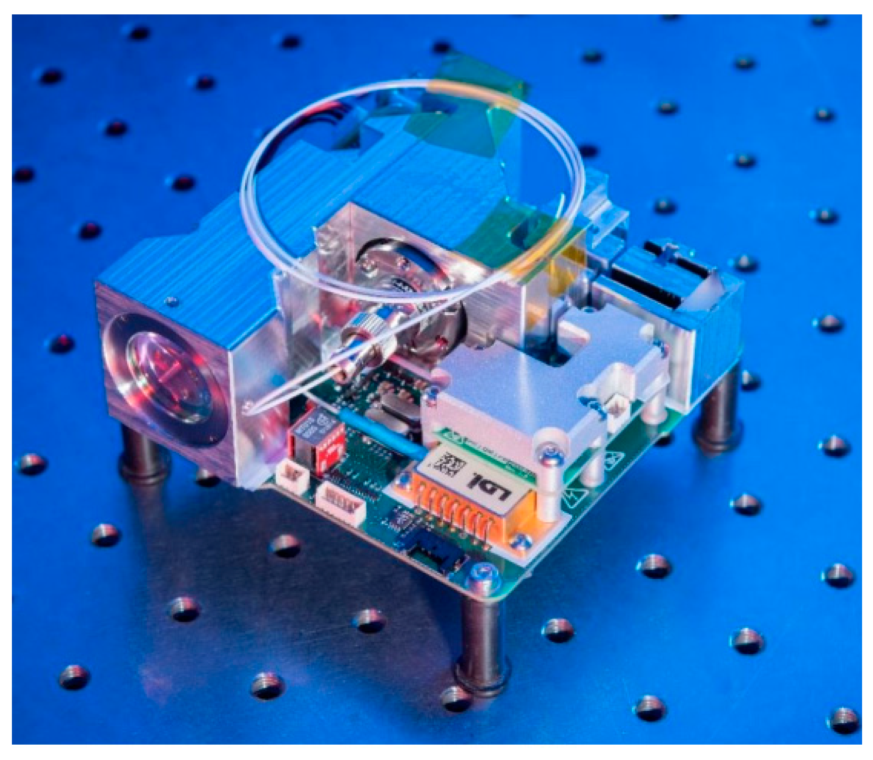
Figure 4.
Cross-section view of magnetic reluctance FSM [58].
Figure 4.
Cross-section view of magnetic reluctance FSM [58].

Figure 5.
Electromagnetically driven MEMS FSM: (a) top and back schematic view of MEMS; (b) cross-section view; (c) schematic 3D model [66].
Figure 5.
Electromagnetically driven MEMS FSM: (a) top and back schematic view of MEMS; (b) cross-section view; (c) schematic 3D model [66].

Figure 6.
Piezo actuator assembly producing amplified linear movement [73].
Figure 6.
Piezo actuator assembly producing amplified linear movement [73].

Figure 7.
LaserCube free-space optical terminal with piezo actuator assembly [81].
Figure 7.
LaserCube free-space optical terminal with piezo actuator assembly [81].

Figure 8.
MEMS FSM actuated by piezo-film actuators: design concept working principle [84].
Figure 8.
MEMS FSM actuated by piezo-film actuators: design concept working principle [84].
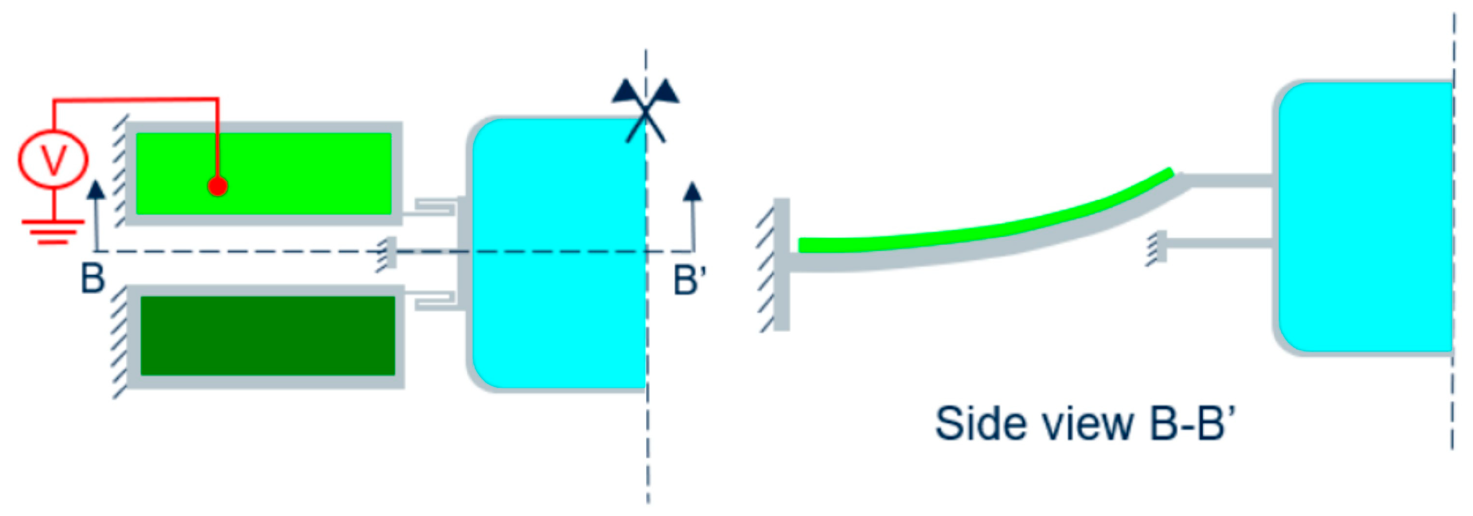
Figure 9.
X-Y translational piezo stage in telescope setup [91].
Figure 9.
X-Y translational piezo stage in telescope setup [91].
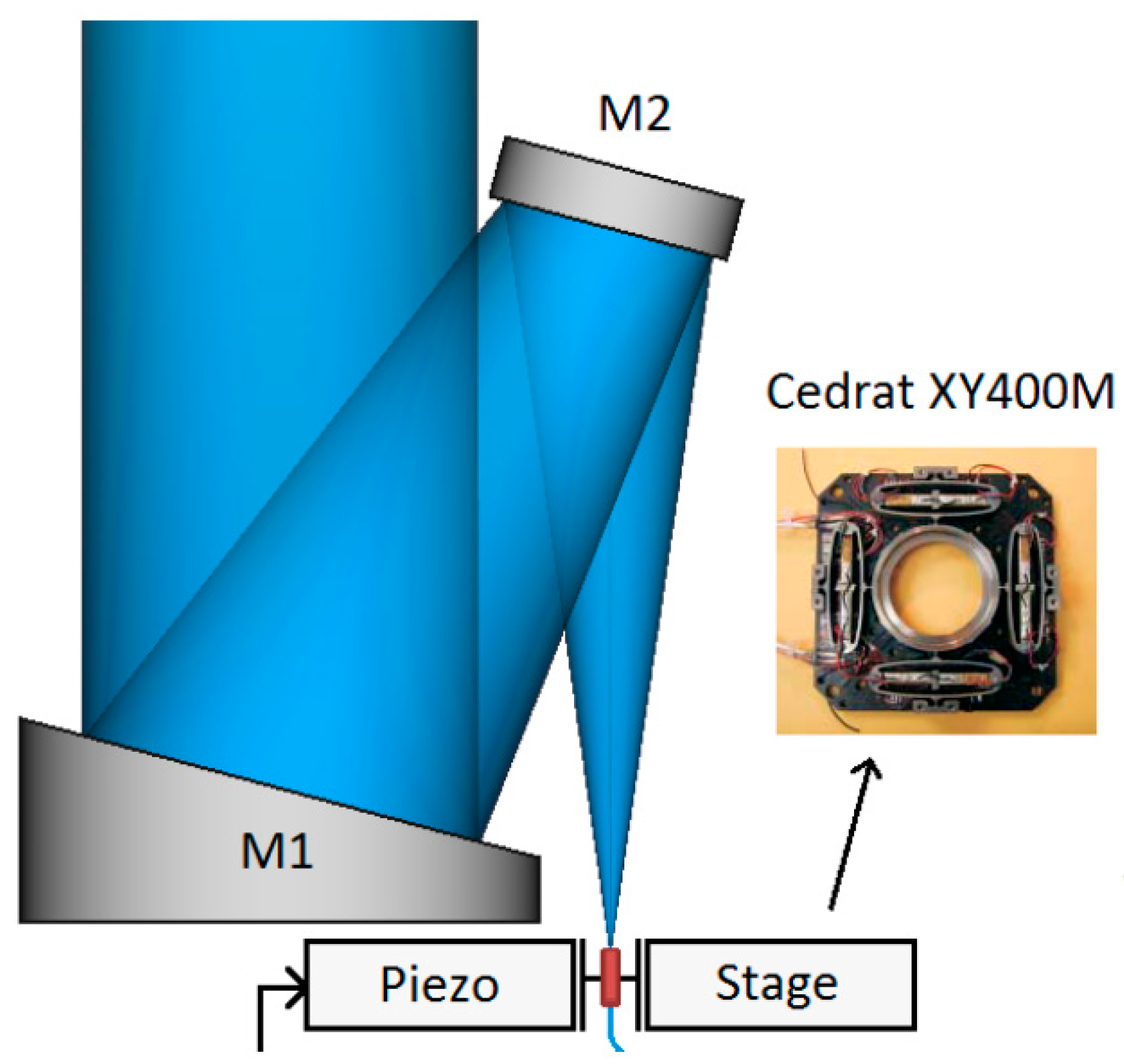
Table 1.
COTS MEMS fast steering mirror providers and performances (Mirrorcle Inc. 2023; Boston Micromachines Inc. 2023; Preciseley Microtechnology Inc. 203).
Table 1.
COTS MEMS fast steering mirror providers and performances (Mirrorcle Inc. 2023; Boston Micromachines Inc. 2023; Preciseley Microtechnology Inc. 203).
| Mirrorcle Technologies Inc. A8L2.2-4600 | Boston Micromachines Hex-111 (3.6 mm) | Precisely Microtechnology Ø3.5 mm | |
|---|---|---|---|
| Optical Power Handling non-vacuum, (mW) | <2000 | n.d. | <500 |
| Total angle range, (deg) | ±5 | ±0.46 | ±2.5 |
| FSM repeatability rms, (arcsec) | 2.5 | n.d. | n.d. |
| Step response time, (ms) | 8 | <0.04 | 1 |
| Mirror’s surface quality RoC—radius of curvature | RoC > 5 m | n.d. | RoC [0.8–5] m |
Table 2.
Main specifications of fast steering mirror with voice coil actuators (Tesat-Spacecom GmbH & Co. KG, 2023; Coppoolse et al., 2003; Jacka et al., 2020).
Table 2.
Main specifications of fast steering mirror with voice coil actuators (Tesat-Spacecom GmbH & Co. KG, 2023; Coppoolse et al., 2003; Jacka et al., 2020).
| TESAT, LCT FSM | CSAG, FSM | ATA, FSM | |
|---|---|---|---|
| Mass, (g) | 300 | 290 | no data |
| Total (mechanical) angle range, (deg) | ±2.1 | ±0.4 | ±0.6 |
| FSM accuracy (mechanical), arcsec | ±1 | ±0.1 | ±1 |
| Closed loop Bandwidth, (Hz) | ≥1000 | 1000 | ≥2500 |
| Mirror WFE rms, (nm) | 15 | 31 | <15 |
Table 4.
Main specifications of commercial electromagnetically driven MEMS beam steering mechanisms (Hamamatsu Corp. 2023, Sercalo Microtechnology Itd MM160110-2-15 Rev. 90-1221-2, Texas Instruments Inc., 2023).
Table 4.
Main specifications of commercial electromagnetically driven MEMS beam steering mechanisms (Hamamatsu Corp. 2023, Sercalo Microtechnology Itd MM160110-2-15 Rev. 90-1221-2, Texas Instruments Inc., 2023).
| Hamamatsu (S13124-01) | Sercalo (MM160110-2-15) | Texas Instruments (TALP1000B) | |
|---|---|---|---|
| Mirror diameter, (mm) | 1.97 | 18 × 12 | 3.2 × 3.6 |
| Power consumption, (W) * with electronics | *3 | 0.6 | 0.7 |
| Total (mechanical) angle range, (deg) | ±5.0 | ±1.5 | ±5.0 |
| Resonant frequency, (Hz) | 480 | 180 | 130 |
| Mirror RoC, (m) | n.d. | >100 | 5 |
| Mirror coating | Aluminium | Gold or Aluminium | Gold |
Table 5.
Qualitative comparison of fast steering mirrors by main design criteria.
| Electrostatic MEMS FSM | Electromagnetic MEMS FSM | Piezoelectric MEMS FSM | Voice Coil FSM | Magnetic Reluctance FSM | Piezo-Stack FSM | X-Y Piezo Stage FSM | |
|---|---|---|---|---|---|---|---|
| Size and weight | Low | Low | Low | Moderate | Moderate | High | High |
| Power consumption | Low | Moderate | Moderate | High | Moderate | High | High |
| Deflection angles | Moderate | Moderate | Moderate | High | High | Low | Low |
| Mirror size | Moderate | Moderate | Moderate | High | High | High | N/A |
| Resolution | Moderate | No data | Low | Low | Moderate | High | High |
| Driver controlling complexity | Low | High | Low | High | High | Low | Low |
| Withstands launch loads | Moderate | High | Moderate | High | High | Low | Low |
| Operational bandwidth | Moderate | Low | Moderate | High | High | High | High |
| Optical power handling | Low | Low | Low | High | High | High | High |
| Flight heritage | Yes | No | No | Yes | Yes | Yes | Yes |
Disclaimer/Publisher’s Note: The statements, opinions and data contained in all publications are solely those of the individual author(s) and contributor(s) and not of MDPI and/or the editor(s). MDPI and/or the editor(s) disclaim responsibility for any injury to people or property resulting from any ideas, methods, instructions or products referred to in the content. |
© 2023 by the authors. Licensee MDPI, Basel, Switzerland. This article is an open access article distributed under the terms and conditions of the Creative Commons Attribution (CC BY) license (https://creativecommons.org/licenses/by/4.0/).
Share and Cite
MDPI and ACS Style
Milaševičius, M.; Mačiulis, L. A Review of Mechanical Fine-Pointing Actuators for Free-Space Optical Communication. Aerospace 2024, 11, 5. https://doi.org/10.3390/aerospace11010005
AMA Style
Milaševičius M, Mačiulis L. A Review of Mechanical Fine-Pointing Actuators for Free-Space Optical Communication. Aerospace. 2024; 11(1):5. https://doi.org/10.3390/aerospace11010005
Chicago/Turabian StyleMilaševičius, Martynas, and Laurynas Mačiulis. 2024. "A Review of Mechanical Fine-Pointing Actuators for Free-Space Optical Communication" Aerospace 11, no. 1: 5. https://doi.org/10.3390/aerospace11010005
Note that from the first issue of 2016, this journal uses article numbers instead of page numbers. See further details here.