
Implementing and Testing a U-Space System: Lessons Learnt
by
 , and
, and
Miguel-Ángel Fas-Millán
1,*,
Andreas Pick
1,
Daniel González del Río
2,
Alejandro Paniagua Tineo
2 and
Rubén García García
3 1
Institute of Flight Guidance, German Aerospace Center (DLR), 38108 Braunschweig, Lower Saxony, Germany
2
Instituto Nacional de Técnica Aeroespacial, Torrejón de Ardoz, 28850 Madrid, Spain
3
Arquimea, Torrejón de Ardoz, 28850 Madrid, Spain
*
Author to whom correspondence should be addressed.
Aerospace 2024, 11(3), 178; https://doi.org/10.3390/aerospace11030178
Submission received: 15 December 2023
/
Revised: 15 February 2024
/
Accepted: 19 February 2024
/
Published: 23 February 2024
(This article belongs to the Special Issue UAV Path Planning and Navigation)
Abstract
:Within the framework of the European Union’s Horizon 2020 research and innovation program, one of the main goals of the Labyrinth project was to develop and test the Conflict Management services of a U-space-based Unmanned Traffic Management (UTM) system. The U-space concept of operations (ConOps) provides a high-level description of the architecture, requirements and functionalities of these systems, but the implementer has a certain degree of freedom in aspects like the techniques used or some policies and procedures. The current document describes some of those implementation decisions. The prototype included part of the services defined by the ConOps, namely e-identification, Tracking, Geo-awareness, Drone Aeronautical Information Management, Geo-fence Provision, Operation Plan Preparation/Optimization, Operation Plan Processing, Strategic Conflict Resolution, Tactical Conflict Resolution, Emergency Management, Monitoring, Traffic Information and Legal Recording. Moreover, a Web app interface was developed for the operator/pilot. The system was tested in simulations and real visual line of sight (VLOS) and beyond VLOS (BVLOS) flights, with both vertical take-off and landing (VTOL) and fixed-wing platforms, while assisting final users interested in incorporating drones to support their tasks. The development and testing of the environment provided lessons at different levels: functionalities, compatibility, procedures, information, usability, ground control station (GCS) integration and aircrew roles.
1. Introduction
A safe use of drones sharing the airspace, same as with crewed aviation, requires a management of the separation. This separation cannot always rely on the skills of the pilots, since many of the operations are expected to be beyond the visual line of sight (BVLOS), with pilots having limited information of the airspace and context. Moreover, the use of human air traffic controllers does not fit well with the particularities of the small drones and the city environment. A better option is to automate an Unmanned Traffic Management (UTM) system. To harmonize such UTM systems in Europe, under the European Union’s (EU) Horizon 2020 research and innovation program, the project CORUS (Concept of Operations for EuRopean UTM Systems) developed and published the U-space concept of operations (ConOps), which would be regulated and adopted in April 2021 as the EU’s UTM ConOps, entering into force on January 2023. The constant research and projects focused on developing and implementing different aspects in the ConOps since the first version was published, have contributed to its refinement, extension and improvement and today version 4 is available [1], addressing new topics like Urban Air Mobility (UAM).
U-space does not only address drone traffic management, but also other relevant aspects like safety, privacy, security, social acceptance or co-existence of all Very Low-Level airspace operations, and its architecture is aimed at facilitating the proliferation of an entire industry around the offer of services provided by and for unmanned aerial vehicles (UAVs). This is permitted by its modular architectural design, which can be seen as a system of systems. Part of these systems are called services, and represent specialized functionalities like calculations or data provision. Services can be dependent on or could make use of other services. For a single U-space, the services can be provided by different companies or institutions and therefore run in different infrastructures; hence, the need for the harmonization for a compatible market.
1.1. Related Work
Four phases have been defined for the implementation of U-space, each of them adding more services to allow for more complex operations. Behind this complexity, there is a more efficient and flexible use of the airspace, able to better satisfy the needs of the airspace users in different aspects. Several recent and current projects have been oriented to develop some of those envisioned services or sub-services. An example is the DACUS (Demand and Capacity Optimization for U-Space) project [2], developing a Dynamic Capacity Management service. With a duration of two years and a half, DACUS suggested a flight plan definition reflecting, on the one hand, the expected uncertainties to comply with the flight plan, which could be determined by factors like weather, communication, navigation and surveillance (CNS) accuracy or the availability of infrastructures like vertiports. And on the other hand, reflecting details of the drone and the trajectory, making it possible to determine the level of annoyance (noise, visual impact) when flying over population and the risk associated, this last value based on the data provided by a Population Density Map service. With all these inputs, DACUS determined, for a given set of flight plans, the hotspots, or areas where the risk of collision or the threshold of annoyance was exceeded, and measures like changes in altitude or delays were suggested in each case to avoid such hotspots. Therefore, DACUS was not providing deconfliction, but the analysis of considerations that, coordinated with the separation services, would bring us closer to a system capable of providing an accepted, safe, efficient and feasible traffic management. The topic of the Dynamic Capacity Management in U-space is also addressed in [3], where a safety condition is required in the management of the traffic density: the aircraft must remain within the range of a landing point along all of its route in case some failure or contingency forces it to land.
Other services that should be in place for a successful deployment cover more technical aspects. The ICARUS project (Integrated Common Altitude Reference system for U-Space) [4] suggested four new services that were later added to edition 4 of the ConOps: Vertical Conversion service, GNSS service, Real-time Geographic Information service and Vertical Alert service. ICARUS proposed that authorities could determine a specific altitude reference in areas where there is a risk of altitude confusion. The importance of a service like this and the coordination of the altitude references was noted during the development of the work described in the present document, as will be later explained.
A key piece and an input for several services is the configuration of the airspace. We should expect to find the airspace divided into different volumes associated to a diversity of constraints, like speed or altitude to mitigate the noise, layers where only drones with certain capabilities would be allowed to fly or areas dedicated to Urban Air Mobility (UAM). If the use of the airspace is to be optimized, this segmentation will probably be dynamic, and a service like the Drone Aeronautical Information Management Service will have to inform of the changes in the structure of the airspace to the airspace users and to the rest of the U-space services affected. The exploratory project USEPE [5] proposed criteria for these subdivisions together with machine learning algorithms to determine in each volume the separation between drones and from manned aviation [6].
One of the most important tasks of the system will be the contingency management. As detailed in [7], its consideration ramifies throughout the entire system and affects all stakeholders. Safety being the main principle to guide the operations, it will affect other features like flight optimization, preferences or priorities. In [8], a method is proposed to evaluate the risk of the operations and suggest measures to the path planning algorithms to mitigate the risk.
Some operations will require specific services and considerations. This is the case of UAM. As a result of the project CORUS-XUAM [9], the last version of the ConOps now includes a Vertiport Availability service. Such service should be based on an analysis of the capacity and demand for a forecast of the availability. This analysis can also support the design of the future vertiports or their expansion. All this and more was the task of the project HorizonUAM; find in [10] the long relation of publications which resulted from this project.
The services mentioned are a small part of all those identified in the ConOps. Some of them are expected from a given implementation phase and some are required only in certain types of airspace volumes. In any case, once having the necessary services with an adequate performance, they have to be coordinated. A harmonized information and communication exchange is necessary to facilitate the compatibility and the competitiveness of the services provided by the U-space service providers (USSPs). Procedures for this coordination need to be described in detail. Criteria will have to be defined to assign the airspace to the users. Policies will have to be set to manage the traffic. Rules need to be established for both the system and the users to respond to contingencies. Defining most of this is the goal of the ongoing project AI4HyDrop (An AI-based Holistic Dynamic Framework for a safe Drone’s Operations in restricted and urban areas) [11]. This project will develop a framework to coordinate the services implied in the submission of a flight plan request and its acceptance. The artificial intelligence (AI) in the project will be found in services like the one creating wind and turbulence models to predict micro-scale effects in the urban architecture; also in the one that will use AI techniques to detect rogue drones; and finally, the Flight Authorization service will make use of AI, for instance, for the strategic deconfliction. The German Aerospace Center (DLR) contributes to this project by adapting and expanding the prototype developed for the project Labyrinth (introduced in the next subsection), which will be used for simulations to validate the solutions proposed.
1.2. The Scope of Labyrinth
The present work was part of the project Labyrinth [12,13], a three-year Horizon 2020 project ending in May 2023. Its main goal was to develop and test the algorithms behind two of the key U-space services: Strategic Conflict Resolution and Tactical Conflict Resolution. The Robotics Lab research group at the University Carlos III of Madrid (UC3M) developed the algorithms to find a feasible path, which was returned as a four-dimensional (4D) trajectory. The details of these algorithms have already been described in other articles [14,15,16,17,18,19,20,21], where their potential can be better discovered, since only part of their possibilities was used in the real flights during the project. The task of the algorithms was to provide the drone operators with a deconflicted trajectory based on their flight intentions, capabilities and some existing constraints:
- Trajectories of other traffic. The occupancy of the airspace considered the time dimension, i.e., if at a given time t the drone is expected to overfly the waypoint n, the airspace left behind, the [0, n − 1] waypoints, is considered available for other traffic.
- Geo-fences.
- Elevation map including buildings.
- Maximum and minimum speed of the aircraft.
- VTOL/fixed-wing capabilities regarding turns and take-off/landing maneuvers.
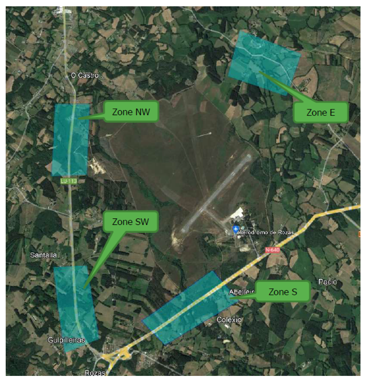
These constrains that UC3M’s algorithms took as input were just part of all the constraints that a system like this should consider, especially if used for relevant traffic densities flying over population. But to develop a strategic or tactical deconfliction service able to integrate more factors we first need services providing such sources of information. Most of those services do not exist yet and would deserve their own project to be developed due to their complexity. As an example, the case of the elevation data used during the project. There were used the Digital Surface Models (DSMs) based on LiDAR (Laser Imaging Detection and Ranging) point clouds available in the web of the Spanish National Geographic Institute. The algorithms used in the path planner had a high computational demand, being limited in the size of the area or work, which had to be previously cut from the DSMs and converted, which is not a quick step. As a result, the tests during the project were limited to some specific areas in Spain and Italy (Figure 1). This is not an option for a service that had to be used in a wide area containing at least a city and its surroundings, or connecting two cities. Moreover, while the resolution of the LiDAR samples was acceptable (5 m), the datasets available were slightly aged ([2009,2012] depending on the sheet), which means that some buildings or vegetation was not reflected in the data. In one of the flight tests later described, it can be seen that the trajectory finally flown had more altitude than that approved by the UTM; the reason was a group of tall trees, which probably were not there or not that high when the dataset was captured; then, the altitude of the approved plan was increased to avoid risks. For a safe and efficient deconfliction service, we would need a service able to rapidly provide specific pieces of recent elevation maps. This is just an example of the many potential business models that U-space allows.
UC3M’s algorithms, in the same way as in the approach of [22], follow a First-Come, First-Served assignment of the airspace. But it would be more convenient to have flights with priorities to support missions like police tasks or medical services. In this case, the submission of a flight plan could mean modifying other scheduled or ongoing flights. But priorities could be associated to criteria like penalties or reputation points in case the authorities decide to motivate the good practices of the airspace users; priorities could be also just a matter of price. In any of these cases, one service should exist to provide the conflict resolution services with the priority of the flight in the deconfliction decision.
The complexity to develop any of the mentioned U-space services, policies or procedures together with their coordination explains why the services implemented in Labyrinth only had the intention to provide a basic functionality. However, it was enough for the exercises to be executed, which were performed in empty environments without people at risk, very low possibility of collision with buildings or infrastructure and a maximum of three drones flying at the same time in the area. We cannot claim that we were implementing a complete Strategic Conflict Resolution or a Tactical Conflict Resolution service since we were lacking many of the inputs required to achieve, for example, the coordination with manned air traffic control. Instead, the main interest behind the experiments described here was addressed to verify how well the process of design and request for approval of the flight plans could satisfy the needs of the final users and detect any need that could not be identified just running simulations without humans-in-the-loop. The flights supported the activities of final users willing to integrate drones into their tasks to increase efficiency. The use cases included: bird shepherding, runway inspection in airports, sanitary supplies delivery, evaluation of an emergency area, support for the evacuation of a mass of people, monitoring of loading activities and surveillance in maritime ports, infraction detection of car drivers and speed measurement of ground traffic. But another interesting source of feedback came from the work of the operators to integrate their platforms. They had to modify their ground control stations (GCSs) to log in the system, receive and load in the drone the flight plan approved, report the position during the flight and receive instructions and information. This illustrated their limitations, needs and preferences, and these should be considered if we want to facilitate the access of the operators to U-space.
DLR was responsible for implementing the services, connecting with UC3M’s path planning sub-service. The Spanish partners Arquimea and the National Institute of Aerospace Technology (INTA) would be in charge of testing the system by adapting their platforms and executing real flights that reflected the needs of different final users involved in the project.
Note that, as a project addressed to implement U-space, there was no creativity regarding the architecture of the system or the expected functionality of its services, and the guidelines of the third edition of the ConOps were followed as close as possible. Therefore, the purpose of the work described here was not to suggest any divergence from the U-space ConOps, and any of the contributions are believed to fall within the implementation freedom allowed by the high-level specifications of the U-space concept.
1.3. Structure of this Paper
The exposition has been divided into the different pieces of the environment, starting with the interfaces with the system, followed by the description of the services implied in the tests, the developments of the operators to integrate their platforms in the environment and ending with an overview of some of the exercises. To better contextualize some suggestions and lessons learnt, these have been spread along the document, in each section describing the topic they belong to, leaving the Discussion Section for other conclusions and ideas or needs for future work.
2. Interfaces
2.1. Web App
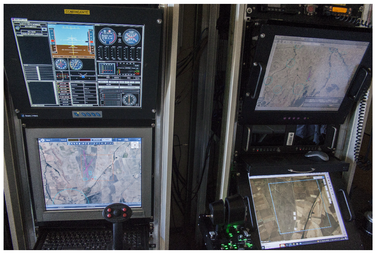
Operators and pilots need a graphical interface to visualize the information and instructions from and send requests to the U-space. An Application Programming Interface (API) was provided so that operators could implement the display of dialogues and information in their GCS. Figure 2 shows this option, chosen by Arquimea. To do this, operators must have access to the source code of the GCS software, which is not always possible, and this integration can be expensive and take some time (both operators during the project used GCS software developed by themselves). Moreover, embedding more elements could result in a cluttered screen, which works against the usability principles. As an alternative, to overcome these problems, DLR developed a Web app to display the dialogues and information from the U-space services. It requires a dedicated screen, something to which the flight crews were reluctant. However, another benefit is that one member of the flight crew can take care of the U-space communications while the pilot in command (PIC) flights manually or monitors the flight status, reducing the cognitive workload of the pilot, which is important in the case of flying swarms. This was the option chosen by INTA (Figure 3).
2.2. The Application Programming Interface
The Representational State Transfer (REST) API defined the way users—GCSs, UAVs and other clients—send requests or reports to the U-space, and how the information or instructions are received. Part of the calls defined in the API can be used to embed the communications requiring a visualization in the GCS if the Web app is not used. The rest is a reduced set that operators must use to integrate the GCS/UAV in the U-space environment (e.g., for position reporting). Figure 4 depicts the flow of messages between the different parts. The reporting of the position or status, like emergency warnings, could be sent to UTM by the drone, the GCS or both redundantly. The instructions arriving directly to the drone from UTM appear in italics because, following the ConOps guidelines, this was not supposed to happen; instructions should arrive to the GCS and be wilcoed or rejected by the pilot. During the project, instructions were not sent directly to the drone, and the image only represents the possibility to do it. The UTM was also not sending information to the drone, but in this case only because the platforms used during the project were not able to process it—an example would have been the presence of a sudden dynamic geo-fence. Requests could be sent from the GCS or the Web app, depending on the decision of the operators to integrate their system. Regarding reports, if only the GCS is used, its reports will include all kinds of them. If the Web app is used, the reports from it are only partially related to specific events like start or cancellation of the flights, or those that make sense to be performed by the pilot to add some specific information. But even if the Web app is used, position reports are expected to be sent from the GCS or the UAV automatically at least at a rate of one per second.
The JavaScript Object Notation (JSON) [23] was chosen as the message format. In these data structures, one can add new fields as needed, not affecting the existing code, and any programming language has libraries to de-/serialize it. Its flexibility permits the use of different fields depending on the capabilities of the drone, or to refer to the same variable with a specific unit/format. It is human-readable and the logs can be easily processed to analyze the tests. To represent the trajectories, the GeoJSON standard [24] was selected. It allows for the definition of a sequence of mixed elements like points and polygonal or round areas that can be used to represent geo-fences or areas to scan. This versatile trajectory definition, rather than a classical flight plan containing a trajectory as a list of only waypoints, fits better to the flexibility that can be exploited when using drones. Another benefit of GeoJSON is the possible addition of several components to the coordinate vectors, which can be used to register the constraints or any other information related to a waypoint. During the flight plan request process, pilots would first send the trajectory they wanted to fly. On it, the coordinates of the waypoints would contain the components of longitude, latitude and altitude relative to the ground. The UTM would forward this trajectory to the path planner, which would return an optimized and deconflicted 4D trajectory based on the draft. In this new trajectory, the components of the waypoints would include sea level altitude, speed and time of arrival (ToA) (Figure 5).
GeoJSON was also used in the flight plan of the DACUS project [25], but in this case accepting only two plan types: trajectories as a list of waypoints or areas within which to fly freely. This format is not the first attempt to allow more flexibility in the definition of flight plans for drones; [26] proposes a flight plan specification to allow for the design of complex trajectories with repetitive and conditional sections.
3. The U-Space Services
The ConOps defines different types of airspace volumes and these require a different number of services. Considering the use cases of the project, some of them are expected inside or close to the city. The developed environment was addressed to the most restrictive Zu volumes, which requires continuous position reporting from the drone, a remote pilot station connected to U-space and an approved flight plan, and in which tactical separation instructions are sent to the traffic when needed. U-space also determines four deployment phases, which gradually add services, some of them mandatory, to allow for each step more complex operations. Being a research prototype oriented to test only some specific services in controlled scenarios, not all of the services required for each phase were implemented before developing a service of the following phase (the Tactical Conflict Resolution service belongs to the U3 level), and only those necessary for the projected validation were implemented. But among those implemented were e-identification, Tracking, Geo-awareness, Drone Aeronautical Information Management, Geo-fence Provision, Operation Plan Preparation/Optimization, Operation Plan Processing, Strategic Conflict Resolution, Tactical Conflict Resolution, Emergency Management, Monitoring, Traffic Information and Legal Recording.
The description of the implementation of these services has been ordered following the categories for these specified in the ConOps. Figure 6 shows the location of the services implemented. The GCS communicated with the Bridge Server; the task of this server was to work as a link between the users connecting via API/Web app and the UTM, and at the same time allow the update of the information in the Web app. Note that this Web app interface could be not only used by the pilots, but also by other users like the operators, authorities, air traffic controllers or citizens, and all of them should receive the update of the events and airspace situation. However, the UAV reported directly to the UTM to avoid the forwarding between the Bridge and UTM; in the case of having only the UAV reporting its position (or in the case of loss link between GCS and UAV), the reports are sent by the UTM to the Bridge which forwards them to the GCS and the Web app. All servers were hosted in the Amazon Web Services cloud, located in Frankfurt, except for the path planner used by the deconfliction services, which was running in a server of UC3M in Madrid. Inside the UTM server can be seen services that are dependent on other services or an extension of it. However, most of the services are interconnected between them, to access the data or receive updates or requests from other services. The Message Delivery Service (in yellow) is not part of the U-space ConOps, but a need identified during the implementation. Many information is generated before and during the execution of the flights and we need to be sure that every user receives the information they need or are allowed to access it. This service takes care of the delivery of the messages so that the GCSs and the Web apps can be correctly updated. Some messages are stored if the user is offline and sent to the user when logging in the system, like the information that a scheduled flight has been canceled or modified due to some change in the airspace environment.
3.1. Identification and Tracking
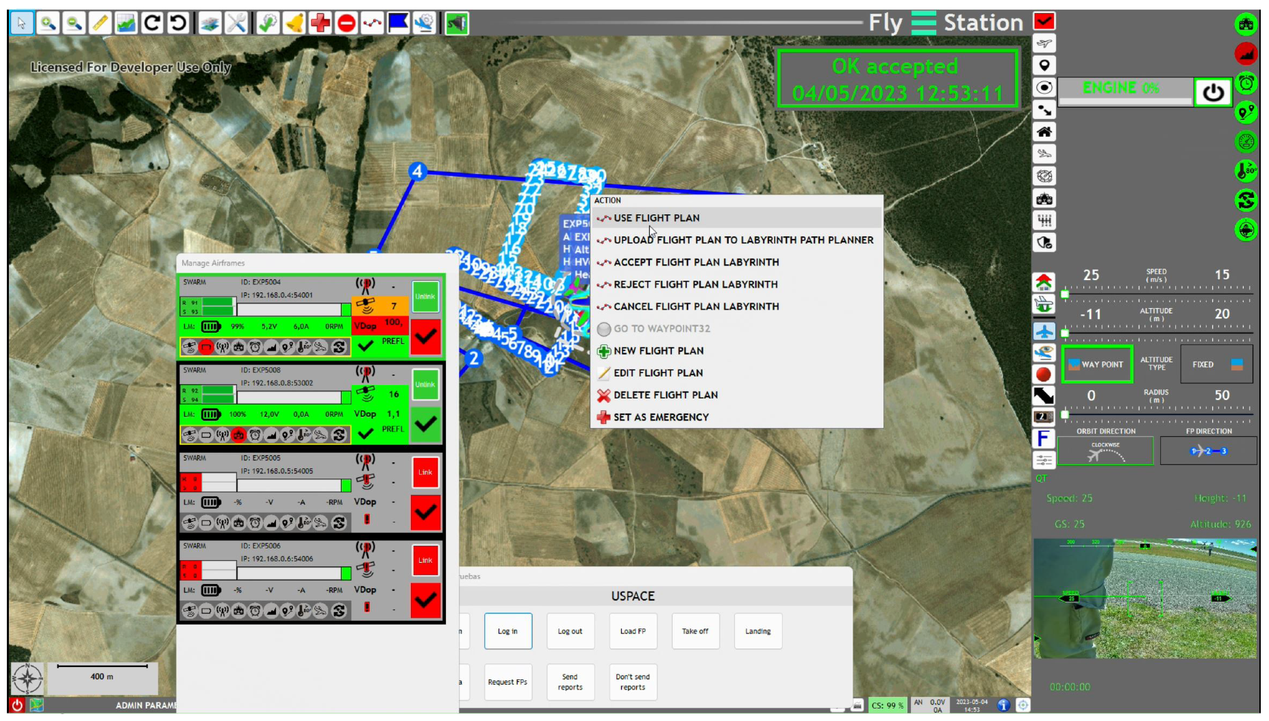
- e-identification Service. The system must maintain updated information on the flights and, if requested, provide the different user types—authorities, citizens and operators—with different details depending on their data access privileges. During the project, the focus was put only on the pilot’s view. In this regard, since it is important to provide an uncluttered screen, to minimize the quantity of information, pilots were asked for the values they wanted to see in the drone tags, and finally only the drone’s unique identifier and some telemetry chosen by the pilots were displayed (Figure 7). A useful value on it is the timestamp, which indicates the moment when the telemetry was measured. Since position reports were expected once per second, a timestamp older than that could mean a loss link event. While in this case users would receive a lost link warning, a look at the timestamp of a drone that remains still in the screen—or that the current zoom level makes it seem still—can rapidly reveal if it is in position hold or if there is some lag or issue in the reporting.
- Tracking Service. In our case, the Tracking Service was only dependent on the Position Report Submission sub-service. Since no other close traffic was expected during the tests, no more position reporting (e.g., ADS-B) or tracking sources were integrated into the service. The Position Report Submission sub-service receives and processes the reports with the drone telemetry received from the UAV or the GCS. This processing includes several tasks like verifying the required periodicity of the reporting, forwarding the report to other services, comparing the coherence between GCS and UAV reporting when both are reported or identifying unexpected values. These verifications could trigger warnings and contingency procedures.In the reports, some fields were mandatory (drone and flight IDs, origin such as UAV/GCS, three-dimensional (3D) coordinates, speed, timestamp, security token) and others were optional (e.g., uncertainty of the values or source, like altitude from a Global Positioning System (GPS) receiver, barometry or infrared). The optional ones were not due to their minor importance, but because they were not being used by any service. Some flexibility in the fields will be necessary, since different platforms can provide different data or in different units and formats. In this sense, we could require a conversion in the GCS or the UAV or allow for different versions of the same data and make the conversion in the service.Regarding the reporting frequency, while it was requested a minimum of one report per second, it could be considered to increase/decrease the frequency based on the speed or the traffic nearby. That would help to reduce the workload in the server, of special interest with high densities. Each of the reports triggers a good quantity of checks in different services, and the updates are broadcast to all connected users.As mentioned, reports could be sent by the UAV, the GCS or by both redundantly. In this last case, the coherence between both sources was verified, which can help to detect spoofing.
3.2. Airspace Management/Geo-awareness
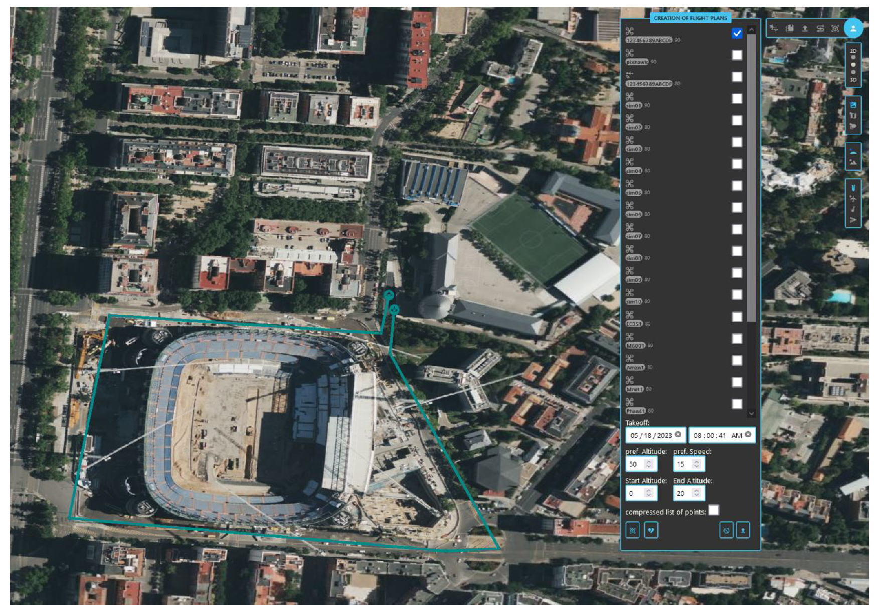
- Drone Aeronautical Information Management Service. The purpose of this service is to collect and supply the real-time information that can affect each flight. In this project, since no other sources of information were available, it is only in charge of keeping the map of existing geo-fences, whether static or dynamic. The definition of the static geo-fences was kept in a file in the server. Dynamic ones could be created/deleted using the API or the Web app, and have an associated duration, name, description and a bottom and/or top altitude (we could have floating geo-fences). The duration could be specified as a number of minutes since its creation or as a date timespan, which is useful to define temporary corridors for priority flights (Figure 8). In principle, only allowed users should be able to create dynamic geo-fences, but for research purposes, like testing the tactical deconfliction service, any user was allowed to create them.
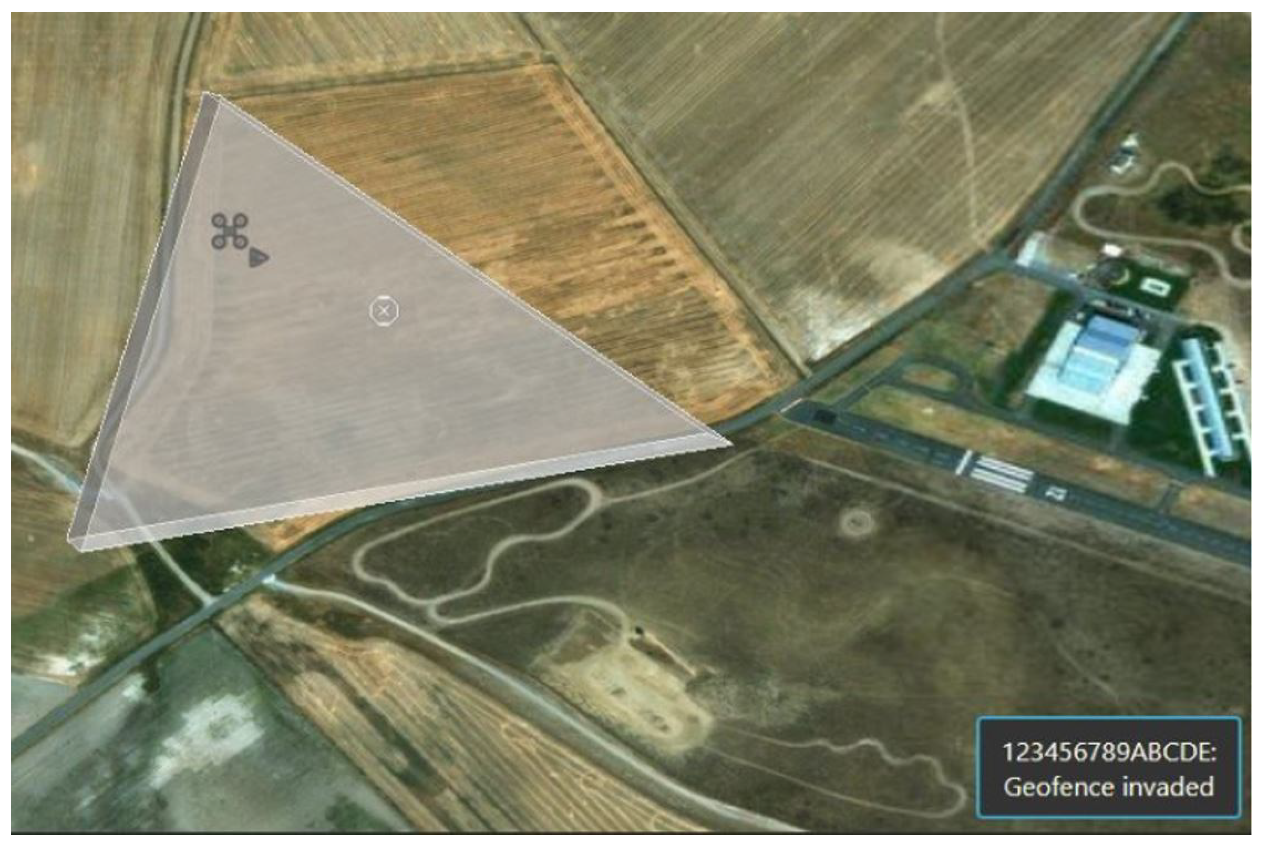
- Geo-awareness Service. When a user logs in, they receive all active geo-fences that can be seen while designing a flight plan. Users may also receive notifications of new geo-fences created or terminated. Dynamic geo-fences were displayed in the Web app in yellow (Figure 9). That way, operators could distinguish them from the static ones and click on them to see the expected time duration. Apart from its informative role, this service also monitors that the UAVs comply with geo-fence avoidance or that they do not leave a geo-cage (Figure 10). If this happens, pilots receive a warning (Figure 11), and tactical deconfliction is triggered if necessary. Geo-cage management was included to support the need of some final users to fly manually inside a segregated area with no predefined trajectory. Inside a geo-cage, the monitoring is addressed to verify that the drone does not get out of it unexpectedly. In geo-cages, a friendly warning is first sent if the UAV becomes close to its limits. This service could include the Geo-fence Provision Service, to directly inform the UAV of any existing or new geo-fence, but the drones used in the project were not able to process this information.
3.3. Mission Management
- Operation Plan Preparation/Optimization. Using this service, operators can submit flight plan approval requests or cancel already approved ones. To help operators to visualize the approved plans, the Web app makes it possible to display one or more plan trajectories in a 2D/3D map view that can be rotated, tilted or zoomed over a clean topographic map background or an orthophoto (the CesiumJS [27] open source library was used for geo-spatial visualization). The trajectories are rendered as a list of waypoints. If one is clicked, the 4D constraints on it are displayed. These features are extremely useful for research purposes, for example, to analyze the separation decisions of the path planner (Figure 12).The functionality determined by the ConOps was that, when the Operation Plan Processing service receives a flight plan approval request, a series of checks and services sequentially look over the constraints and factors that can determine the feasibility of the flight. The reply would be the acceptance of the flight plan or an informed rejection, to provide to the operator the clues to submit a feasible alternative. However, a validation mode is suggested, where the checks are applied, but the plan is not scheduled if found feasible; this mode can help the operator to optimize the flight. In Labyrinth, this optimization was included in the approval request step. Operators sent their flight requests as a draft of the desired trajectory and a set of preferences, and, if the path planner found no conflicts, returned a deconflicted, feasible—in terms of the drone capabilities—and optimized flight plan based as close as possible on the draft.The flexibility of the trajectory design and allowed preferences were determined by the path planning sub-service (Figure 13). Such flexibility will be key to satisfying the needs of the final users. Labyrinth’s path planner calculated trajectories for drafts defined as: origin and destination; origin, an area to scan and destination (the planner returned a pattern to scan the area (Figure 14)); or as origin, a list of waypoints and a destination. However, it was learnt, after the exercises with the first responders, that an option defining origin, a geo-cage and destination should be added. Geo-cages were requested when trajectories in the area could not be decided beforehand since they depended on the needs of each situation. An example would be a drone arriving at an area of interest to follow the unpredictable movements of a mass of people.
- Operation Plan Processing. It handles the list of pending flights and processes new ones. When this service receives a new request for flight permission, after successful syntactic and semantic checks, it adds the geo-fences and traffic affecting the requested trajectory at the moment of the flight, the drone capabilities—max. and min. speed, climb/descend rate, type (VTOL/fixed-wing)–and forwards the request to the Strategic Conflict Resolution Service, which subsequently calls the path planner sub-service. The planner returns, if found, a feasible and optimized trajectory with the hard constraints applied and the soft ones when possible. Paths are really treated like a tube by the planner, providing a radius of separation along it to consider possible relatively light and unavoidable deviations due to navigation inaccuracies or wind. The resulting flight plan is sent to the operator, who must verify whether it fits their needs and accept or reject it. To ease this decision step, it is important to provide a clear and informative display of the plan returned. Moreover, the number of waypoints in the trajectory should be as reduced as possible, since some drones have a limit in the number of points that can be stored in the flight controller.
3.4. Conflict Management
- Strategic Conflict Resolution This service is in charge of returning deconflicted 4D flight plans, where the fourth component was given by the ToA at the waypoint or the speed on it. The reason to provide two constraints to achieve the 4D compliance (speed/ToA) was that, depending on the platform, the UAV was capable to consider and try to comply with one or the other value; e.g., speed in the case of INTA’s DJIs. The Strategic Conflict Resolution depends on the path planner sub-service, whose capabilities and flexibility will have a substantial impact on this and other services. In Labyrinth, the trajectory was not only deconflicted from the traffic and geo-fences at the moment of the flight, but it was also considered the elevation map of the area—a Digital Surface Model. The availability and reliability of these maps is key for optimized and safe trajectory planning. For this project, we had the support of the Spanish National Geographic Institute (IGN) [28]; different types of elevation maps of almost the whole country can be found freely available in their website.No distinctions between the airspace users were implemented during the project, in the sense that, for example, the airspace was not partitioned in areas or levels for different UAV capabilities, and it was assigned in a first-come, first-served basis. But, when existing, these policies should also be taken as input by the path planner. Finally, there was a difference between the plans calculated for the fixed-wing and those for the VTOL UAVs. The first waypoint for the fixed-wing would be at a certain altitude, and the drone would autonomously calculate the maneuver to reach it. Therefore, in this case, two segregated volumes around the take-off and landing points were considered, big enough for the aircraft to execute its climbing/descend maneuver.
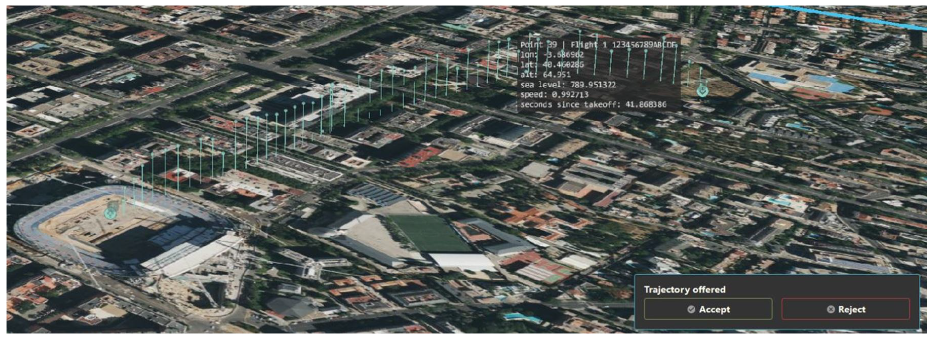
- Tactical Conflict Resolution. Some events could have an impact on the ongoing flights; aircraft unable to comply with the expected 4D constraints, malfunctions or sudden geo-fences (Figure 15) are some examples. When this happens, thanks to this service, the affected traffic automatically receives instructions to avoid the conflict. This service also makes use of the path planner, which, together with the new constraints, should consider which kind of instructions is the aircraft able to execute during the flight due to its capabilities or status. The importance of this was seen while testing with a drone connected to the U-space via satellite communications (satcom) (Figure 16). Together with Telefonica I + D, and the Network Technologies research group from UC3M, part of the project was focused on identifying requirements and suggesting an infrastructure—both ground and airborne—to support a reliable connectivity of the drones. A smart link switcher was developed [29], and DLR studied the impact of satcom users in the environment and the need for any special measure for them. From the tests, it was learnt that it should be avoided to send large portions of data, e.g., an entirely new trajectory, to a satcom-linked drone. In this case, only simpler instructions like position holding, changes in altitude or speed were feasible. Sending a detailed trajectory could take so much time that the drone could not be able to receive and execute it on time to avoid the conflict.Also important is to include in the conflict resolution procedure the estimation of the time for the instruction to reach, be accepted and applied by the pilot. An example is illustrated by the instructions to overwrite the remaining trajectory: if the first new waypoints are close to the current position (consider a case like that of Figure 15), while the instruction is wilcoed and loaded, the drone could have overflown them already, forcing it to backtrack.One particular tactical deconfliction situation appears when the operator needs to abort and change the current flight plan. This capability was fundamental for missions like those of the first responders, who must adapt their support to the development of the events. In those situations, the chosen procedure was the following. First, the pilot requested a cancellation of the current flight. The UAV should then be kept hovering until the end of the procedure. Automatically after the cancellation request, a safety dynamic geo-fence was created around the UAV and any traffic affected was deviated. In the case of fixed-wings, the geo-fence size was tailored to give room to the holding loop pattern required by the aircraft. Pilots could then design and submit the new plan. After a successful approval process (i.e., no conflicts found), and before starting to execute it, they had to send a start-of-flight message. When doing it, the geo-fence was removed and they could start the new plan. With little practice, the aircrew became used to this procedure and executed it rapidly. If they forgot to send the start-of-flight message, they received a warning when the safety geo-cage was left, so they could immediately solve it. A similar procedure was provided for those cases wherein the need was to stop and fly manually in the area without a predefined trajectory. Here, after canceling the ongoing plan, operators would ask for a geo-cage, broadcast as a new geo-fence to the rest of the traffic. When the area was segregated (other drones of the same operator were allowed), the operator could start flying freely inside it; within it, the separation was a responsibility of the pilot.
3.5. Emergency Management
This service was not developed in depth since non-nominal situations were out of the scope of this project. However, warnings were included to inform the pilots of relevant events. A warning message type could be used by pilots or the UAV autonomously to report any problem. If sent, it was broadcast to the traffic nearby and the Web app showed the drone surrounded by a red cube representing a wider separation to provide a margin of time for a tactical deconfliction of close traffic (Figure 17). The same procedure was applied for those contingencies that could be automatically detected by the system, like deviations.
There was a message to report a link loss of the UAV with the GCS; in that case, if the drone was still able to report to UTM, the position reports were forwarded to the pilots, so that they could be informed of the location of the drone.
3.6. Monitoring
The three following services of this category were implemented:
- Monitoring. As aforementioned, when it comes to comply with the waypoint constraint related to the fourth dimension of the 4D trajectories, depending on the drone, it could be capable to try to comply with speed, ToA or none of them. The implemented conformance monitoring service may consider this while verifying whether the trajectory constraints were met. With respect to the 3D position, a light deviation warning was sent when the aircraft came notably apart from the planned route (10 m radius) but still inside a deconflicted tube (of 20 m radius) reserved by the path planner around it. If leaving this tube, a severe deviation warning was sent, traffic around warned and the tactical separation service was triggered if conflicts appeared.
- Traffic Information. Users received constant updates on the positions of the close traffic, warnings or information like flight cancellations and their reason. In the Web app, the icons of non-nominal flights appear with a warning icon, together with the mentioned red shield box (Figure 18, bottom right). Lost link events between the UAV and U-space or the GCS appear with different color icons in the flight strip that represents the flight status and its associated actions in the interface (Figure 18, top right), and some other events will print a textual message for the pilot, together with an aural warning for the important events or those requiring immediate attention.However, after watching the aircrew using the interface during the tests, it was obvious that an improvement in the usability of the Web app was required. Future work should be directed to allow for the filtering of some non-critical types of messages. This filtering could be set manually by the user or determined in a smart way by the system depending on the kind of user or the current situation, i.e., if a pilot is currently flying a drone, is it appropriate or necessary to display to the pilot in that moment messages about other canceled plans? Within which distance from the flying drone does it make sense to warn a pilot about other drone in distress? Also to reconsider was the way the textual warnings were shown to the pilot (Figure 18, left). To be sure that the pilot would read the important messages, pop ups were displayed in the right bottom corner of the screen and they would not disappear until the pilot clicked on them. The option of a warning displayed for some seconds was discarded because the pilot could be looking at the GCS in that moment and miss it. But when a series of important events happened, this resulted in a stack of messages (Figure 19) and an annoyed pilot struggling to close them or just ignoring them. A better way to display these events must be chosen to avoid adding more mental workload to the pilots while keeping them aware of the details of the safety-relevant events. Here again, a mix of a smart warning functionality able to evaluate the need of a warning for a specific user, and a more appropriate display element, could be the solution.
- Legal Recording. Communications related to the flights, events, user requests and errors were registered in log files for later analysis. These would also be used by the partner Austrian Institute of Technology (AIT) to train the algorithms that would detect unexpected values and therefore possible spoofing [31]. AIT also developed a methodology to analyze the information exchange in the environment, identify weaknesses and weigh the impact of a possible cyber-attack [32].
4. GCS Integration
This section comments on the efforts of Arquimea and INTA to integrate their platforms into the U-space environment.
4.1. Arquimea
As previously said, Arquimea chose to embed the dialogues with U-space in their GCS instead of using the Web interface. The main reason for this was related to the peculiarities of fixed-wing take-off and landing maneuvers. During take-off, fixed-wing aircraft heavily rely on the wind at the precise moment of the maneuver, making it challenging to plan its trajectory well in advance. Moreover, there exists a transition period after take-off, during which the aircraft reaches the desired altitude and then follows the planned flight path. Predicting this transition accurately is complex. Similarly, during the landing maneuver, there is a transition between the last point of the flight plan and the beginning of the descent orbit. This descent orbit may be performed multiple times to achieve the desired altitude and start the landing phase. The management of these peculiarities was addressed by the GCS software. There was no need or reason to delegate it to the path planner. The GCS would add the necessary maneuvers to the trajectory returned by the Operation Plan Processing service. Therefore, it was more convenient to perform the request process already in the GCS, since these maneuvers would not be displayed in the Web app.
Regarding the technical aspect of the integration, the processing of the JSON messages was straightforward thanks to the existing libraries for C#, the only problem being the incompatibility between some JSON field names and the variable names permitted in C#, which prevented an automated deserialization.
4.2. INTA
INTA’s aircrew was formed by a Pilot-in-Command (PiC), an external pilot, two payload operators (one of them also in charge of the U-space communications using the Web app), one visual observer, a platform engineer and the subject matter expert of the exercise (the final user). At a given moment, the PiC was managing up to three drones at the same time flying BVLOS, including communications with air traffic control, since the drones took off from the aerodrome Rozas Airborne Research Center (CIAR). However, they concluded that an improved integration would allow the PiC to also assume the U-space communication tasks. Examples of that improvement would be to automatically load the plan into the drone when the PiC accepts the route suggested by the Plan Processing service, or the automated loading in the drone of the commands when an instruction is wilcoed by the pilot. At the moment of the tests, such steps were only partially automated, requiring some coordination between the PiC and the person in charge of the U-space communications.
5. Tests
This section describes the flight tests performed by Arquimea and INTA. Prior to these exercises, there were simulations and real flights to test the system. Other planned tests in maritime ports could not be executed in the time-frame of the project in the end and were only evaluated in simulations.
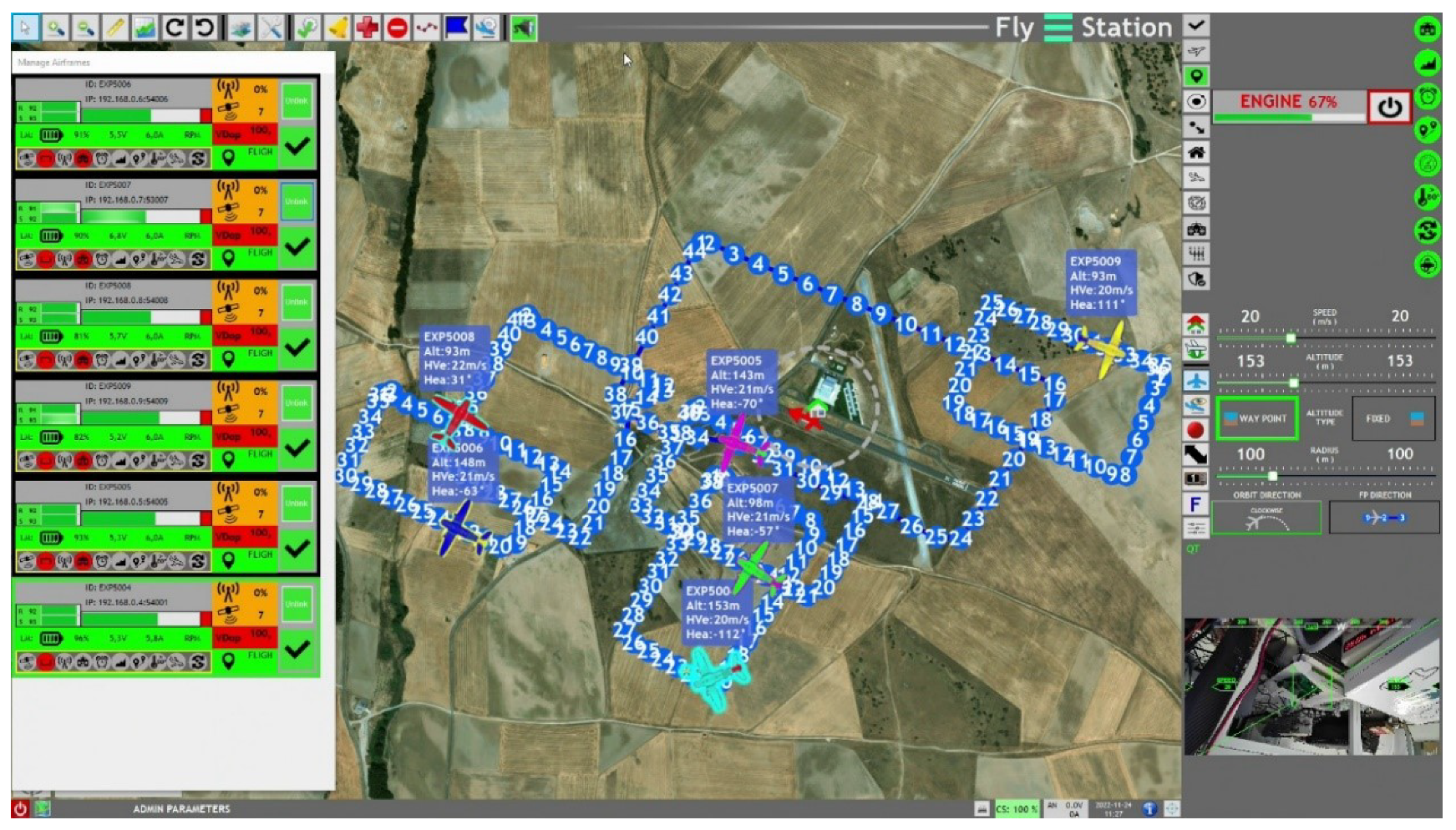
The tests for the use cases performed by Arquimea included three tasks: bird shepherding to avoid bird strikes in airports, airport perimeter surveillance to detect potentially dangerous intrusions and runway inspection to detect possible debris that could damage the airplanes during taxing, take-off and landing maneuvers. Arquimea did the tests with the fixed-wing UAV they used in their bird shepherding services (Figure 20) and they performed tests including at the same time a different number of simulated drones in the vicinity (Figure 21). The validation included the use of the smart link switcher developed by UC3M in the work package focused on the communication needs. Both the GCS and the UAV, with its 4G link, reported to the U-space.
During the flights, some errors in the reporting lead to the UTM to trigger deviation warnings (Figure 19). This unveils another research need. Since this kind or errors can lead to deconfliction procedures, with possibly an impact in the performance of the rest of the traffic and on safety, it is necessary to minimize the reaction to false positives, by providing some margin of flexibility in the expected reporting, within a margin of safety, before triggering a warning; otherwise, by finding alternative ways to verify the reliability of unexpected report values.
While UC3M developed different deconfliction modes for their path planner during the project, only one of them was used in the flight tests and this one deconflicted the traffic, basically moving it to different altitudes. Therefore, Arquimea highlighted the need of working with reliable and coordinated altitude references.
INTA validated the U-space solution executing missions with tasks of ground traffic surveillance and support to medical first responders. In the first case, this required the drones to move to specific segments of different roads, and there freely move and position to inspect the traffic in the most convenient way (Figure 22).
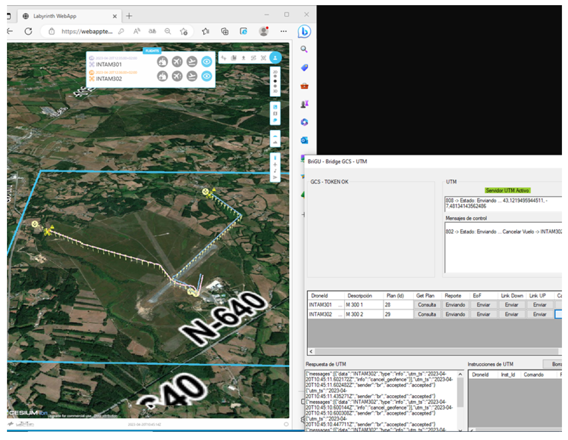
Therefore, the flight plan should make it possible to define the trajectory to the area of interest, then define a geo-cage there, and then subsequently a trajectory to another point with its geo-cage of interest or the path back home. However, the path planning service would not support this kind of flight plan configurations, and the end of a trajectory was expected to be the ground, not a floating geo-cage. This can be seen in Figure 23 and Figure 24, in which the trajectory assigned by the planner ends on the ground but not the one requested (the draft trajectory) or the one finally flown. The deviation between the altitude assigned for M302 and that flown had to do with a preventive increase to avoid some high trees which probably were not reflected in the elevation map used by the path planner.
The alternative was to create a procedure to satisfy this kind of needs during the flight; this is the procedure described in the Tactical Conflict Resolution section. INTA would request a simple plan to the point of interest. Once there, they would cancel the ongoing flight to fly in a previously requested geo-cage in that place (Figure 25). After performing the inspection tasks, they would request a new plan to move to the next point of interest or back home. While this made it possible to execute the required mission with the same path planner, UC3M had to implement the possibility to start/end the flights from/to a specified altitude. Figure 26 shows the moment of this exercise when two drones are in their destination geo-cages recording the ground traffic. At right can be seen part of the dialog of the middleware that INTA developed to monitor the communications with UTM. On it they could check the status of the connection with U-space, if the reports were being sent, the confirmation replies from the UTM and the instructions received.
Two DJI Matrice 300 RTK (DJI, Shenzhen, China) were involved in this exercise, both equipped with a DJI Zenmuse H20 camera. The need of a camera with a high performance was related to the use of a software during the surveillance that used computer vision techniques to act a as flying speed radar. The tool would tag the cars in the video feed provided from the drone with their speed in real time (Figure 27).
This same feed could be used, if some infraction was detected (using the smartphone while driving, or with no seat belt on), to read the car plate, even when the flights were at such a high altitude (in some cases, in the limit of the allowed 120 m) that the people or the drivers overflown would not notice or hear them (Figure 28).
INTA was also in charge of the validation of the use case to support medical first responders. SAMUR-Protección Civil (Servicio de Asistencia Municipal de Urgencia y Rescate) is the public medical emergency system of Madrid metropolitan area and another final user interested on using drones to support their tasks. In these exercises, a swarm of three drones was used (all Chinese commercial Off-The-Shelf, two DJI Matrice 300 RTK and a DJI Matrice 600). In the first exercise, the drones were used to locate a reported (simulated) car accident in an area of difficult access, evaluate the actions to take, deliver medical supplies, and guide the ambulance to reach to and exit from the location of the accident. The final user reported the need to detect from the air any blocked access, the terrain conditions that would prevent the ambulance from reaching to the point or simply inform of the paths with less traffic. The exercise started by sending a drone to exactly locate the accident, inspect the situation and determine the actions to take (Figure 29a). Here, we find again the need to provide a safe procedure to cancel and modify the ongoing plan once the target has been found. Concretely, in this case there was no need to ask for a geo-cage since the drone had no intentions to move from its holding position and the UTM already automatically created a protective geo-fence when the plan upon execution was canceled. From the GCS site, the first responders agreed to send a defibrillator to be used by one person present in the point of the accident. A second drone (the Matrice 600) with an adapted rack takes off to deliver the defibrillator (Figure 29b). Meanwhile, an ambulance is sent to the accident. The payload operator and a member of SAMUR in the GCS verify the ways of access from the drone and the ambulance is informed about them by radio. The ambulance arrives and the victim is assisted and prepared to be introduced in the ambulance (Figure 29c). While this happens, the first drone, which was low on battery, is replaced by another one, which will be used to guide the ambulance on its way back.
An issue appeared related to the conversion of the altitudes; the Matrice 600 was not able to take-off and fly back home after delivering the defibrillator due to inconsistencies in the altitude values. The drones took as reference the relative altitude to the take-off point. To adapt the value of the mean sea level (MSL) provided by the path planner to the relative altitude of the drone, the difference between the altitude values along the trajectory were subtracted from that of the first take-off point (home point). But when the drone landed to deliver the defibrillator, the area was slightly under the home point used as reference, and the result of subtracting it was negative altitude, e.g., take-off point at 210 m, set as ground level reference 0 m for the whole mission; second waypoint at 215, ground level reference 5 m; landing; the path planner determines that the second take-off is at 205 m, and the ground level reference is calculated as .
The second exercise with SAMUR was addressed to use the drones during a mass event wherein an emergency resulted in a confused mass of people running to escape from a danger. The previous three multi-rotors would be used again to help the people to evacuate the area. INTA found this exercise the most demanding in terms of workload for the aircrew. It was also performed in the CIAR aerodrome, but a set of geo-fences simulated the environment of the stadium Santiago Bernabéu in Madrid and the surrounding buildings (Figure 30).
Initially, two drones (Matrice 300) were executing routine surveillance L-shaped flights in a loop along opposite sides of the stadium (Figure 31, orange and light blue). Suddenly, one of the drones identified a suspected threat and canceled its current flight to hold position and inspect the target.
The other drone also canceled its flight and moved toward the target, at a lower altitude, to get a closer look. After inspection, SAMUR determined that it was necessary to evacuate the area. One of the drones was sent back home and was substituted by the Matrice 600 equipped with a megaphone (Figure 32).
A member of SAMUR, from the GCS, used the megaphone to ask the people in the area to follow the strobe lights of the other drone and be guided through a safe escape way. Since the evacuation had been determined, a big geo-cage (Figure 10) was created to segregate the area from traffic that could disturb the operation. Drones from a same operator were allowed in a geo-cage but then the separation was a responsibility of the pilots, since the geo-cages were asked mostly to fly freely inside, without a predefined trajectory. However, in this case the pilot trusted the UTM to maintain the separation also within the cage, asking for trajectories even to move inside of it. While this could seem unnecessary since no other traffic would be left inside the geo-cage and conflicts cannot be expected in that sense (except from other drones of the same operator), consider that the path planner will return trajectories avoiding the obstacles that it is aware of, like trees or lampposts, and at a safe distance from the buildings, which is also helpful.
6. Discussion
The development of the U-space prototype, and especially testing it in different use cases, provided valuable knowledge of the needs of final users, operators and pilots, limitations and capabilities of the drones and challenges of the environment and missions. The experience showed that, to facilitate different kinds of operations, the system must provide flexibility, both to design the plan and to modify the ongoing flight. The implementation must be able to adapt its services to the heterogeneity of UAV platforms with different capabilities, especially with regard to the differences between VTOL and fixed-wing. Concretely, the versatility and performance of the path planning sub-service will have a great impact on the system, from allowing the operators the definition of trajectories that fit to their needs to, depending on the way the separation is managed, the capacity of the airspace.
The decision to automatically optimize the paths, receiving from the operators drafts of plans that could be as simple as origin and destination, and returning a detailed 4D trajectory, fitted perfectly with the needs of users like first responders, since sometimes they need to rapidly design and submit a plan during critical situations when a slow manual optimization is not an option.
If a definition of the messages between U-space and the drone/GCS was agreed upon, with the expected information, units or format, manufacturers could provide tools or functionalities oriented to ease the integration of their drones. An example is the case of the capability to execute a 4D trajectory. INTA used their own implementation to comply with the speed constraint in the waypoints, since the M600 did not have this capability. The new DJI Onboard Software Development Kit (OSDK) version 4.1.0 for the M300 drones acquired during the project already provided this functionality (“M600 and A3/N3 only support OSDK 3.9 or below; […] M300 RTK only support OSDK 4.0 and above.” [33]); the new firmware not only makes it possible to associate constraints to the waypoints but also actions [34]. However, since INTA used the same software to control all drones, it was fitted to the case of the M600, preventing it from taking full advantage of the new capabilities of the SDK 4.1. To implement the 4D capability, the position of the drone was monitored and, when it reached one of the waypoints of the flight plan, the speed was adjusted to that expected. One feature leveraged, already present in the version 3.9, was the auto-landing. And another to remark in the last version is the possibility to modify the home-point during the flight, which provides flexibility for the design of contingency plans.
A pending work regarding tactical deconfliction is considering the battery level to avoid sending instructions to the drone that could result in an emergency procedure. Another request was a clear definition of the responsibilities related to actions and decisions in the event of contingencies: when and how can one expect support or coordination from U-space? When should you act unilaterally, even if it would imply a risk due to some lack of information? Also guidance to design the contingency plans during the flight plan creation is needed. If the operator wants to determine a safe landing point in case of failure, they could only use the clues of an orthophoto, which could be outdated. And the picture does not provide information of elements like the presence of cables or if it is an area where people can be present. An emergency management service should meet these needs.
In the current implementation, given a contingency, the traffic around is considered affected and re-routed only when its trajectory conflicts with the generator of the event. Future work could consider a more preventive separation if a problem in the area is reported. For instance, even if the route of the traffic is not yet affected but a future conflict can be inferred (e.g., a rogue drone).
One of the main challenges during the implementation of the UTM was having several services interconnected and events that trigger different actions in various of them that sometimes require a specific order of execution and updates in the data structures of the services. This complexity, despite having implemented only a small part of the expected services, suggests the difficulties that will imply integrating more services and sources of information. A careful design and documentation of the architecture and the sequence of actions to attend to each event from the beginning of the development is fundamental.
Another topic to which pay attention will be the resilience of the system to communication fails. In the case of position reports, a reporting gap triggered actions associated to an assumed lost link, which could lead to unnecessary deviations and warnings to the rest of the users even when the problem was just temporal. Instead, the reaction of the system could be adapted to each situation, i.e., increasing the margin of time to trigger such actions depending on the risk associated, or obtaining the support of other tracking sources. During the experiments, the quality of the communications was not a problem, since the flights were realized in flat and empty areas, without obstacles, sources of interference and a good coverage, so no relevant package loss was seen. But we cannot expect the same flying in other conditions, like while overflying a city with more traffic density. However, the streaming of the video from the drone failed several times, which was a problem for the situational awareness but particularly for the drones whose mission depended on the images captured—evaluation of the area with the emergency, or the monitoring of the traffic. This was despite the fact that M300 allowed for the use of a transmission channel dedicated to payload.
With respect to the graphic interface, its usability, adaptability and a clear display of the relevant information, will influence the mental workload of the flight crew and how fast the tasks can be performed, which will be important in the case of operating swarms. In this regard, the feedback of users is fundamental. Therefore, a successful development should go hand in hand with operators, pilots and GCS developers, this being the best way to identify needs and constraints at all levels.
Author Contributions
Conceptualization, methodology, M.-Á.F.-M.; software, M.-Á.F.-M., A.P., A.P.T. and D.G.d.R.; validation, D.G.d.R. and R.G.G.; writing—original draft preparation, M.-Á.F.-M.; writing—review and editing, M.-Á.F.-M., D.G.d.R. and R.G.G. All authors have read and agreed to the published version of the manuscript.
Funding
The Labyrinth project received funding from the European Union’s Horizon 2020 research and innovation program under grant agreement No 861696.
Data Availability Statement
The data collected during the tests described in this article were the videos recorded from the drones and the log of the position reports during the flights. The videos cannot be shared due to privacy restrictions. For the flight data, contact the authors.
Acknowledgments
The authors would like to thank for their valuable contributions to this work to: David Saiz Vázquez, who developed the real-time computer vision-based car speed measurement tool and its Web interface, used in one of the use cases; Jakob Tröschel, responsible for the integration of U-Fly (DLR’s GCS) and a drone platform, in the U-space environment, necessary for the satcom tests, for which he also had to modify the satcom solution; Atmosphere, the company providing the satcom solution, cooperated by supporting with technical assistance and special access to their resources so that their solution could be adapted to the needs of the drone to connect to the U-space server; Aditya Devta, responsible for the simulations and analysis of the path planner sub-service; Jose Manuel Mateos García, in charge of integrating Arquimea’s GCS in the U-space environment and performing their flight tests; the Rozas Airborne Research Center (CIAR), providing the infrastructure and support for the real flight tests of part of the use cases; and the Spanish National Geographic Institute for their help to work with their elevation maps.
Conflicts of Interest
Author Rubén García García was employed by the company Arquimea (Spain). The remaining authors declare that the research was conducted in the absence of any commercial or financial relationships that could be construed as a potential conflict of interest.
References
- CORUS-XUAM Project 2023 U-Space ConOps 4th Edition SESAR. Available online: https://www.sesarju.eu/node/4544 (accessed on 9 December 2023).
- DACUS Project. Available online: https://dacus-research.eu (accessed on 23 February 2024).
- Tang, Y.; Xu, Y.; Inalhan, G. An Integrated Approach for On-Demand Dynamic Capacity Management Service in U-Space. IEEE Trans. Aerosp. Electron. Syst. 2022, 58, 4180–4195. [Google Scholar] [CrossRef]
- Integrated Common Altitude Reference System for U-Space (ICARUS) Project 2020–2022. EU Horizon 2020 Research and Innovation Program. Available online: https://www.u-spaceicarus.eu (accessed on 23 February 2024).
- USEPE Project. Available online: https://usepe.eu (accessed on 23 February 2024).
- Arntzen, A.A.; Cabañas, E.N.; Güldal, S.; Dahle, O.H.; Bueno, J.; Dullweber, M.; Giersch, S.; Coyne, M.A. Model for a Safer Drone’s Operation in an Urban Environment. In Proceedings of the International Conference on Unmanned Aircraft Systems (ICUAS) 2022, Dubrovnik, Croatia, 21–24 June 2022. [Google Scholar]
- Altun, A.T.; Xu, Y.; Inalhan, G.; Vidal-Franco, I.; Hardt, M. Contingency management concept generation for U-space system. In Proceedings of the Integrated Communication, Navigation and Surveillance Conference (ICNS), Dulles, VA, USA, 5–7 April 2022. [Google Scholar]
- Su, Y.; Xu, Y.; Inalhan, G. A comprehensive flight plan risk assessment and optimization method considering air and ground risk of UAM. In Proceedings of the IEEE/AIAA 41st Digital Avionics Systems Conference (DASC), Portsmouth, VA, USA, 18–22 September 2022; pp. 1–10. [Google Scholar]
- CORUS-XUAM Project. Available online: https://corus-xuam.eu (accessed on 23 February 2024).
- Publications of the HorizonUAM Project. Available online: https://www.dlr.de/fl/en/desktopdefault.aspx/tabid-18246/29007_read-76340 (accessed on 23 February 2024).
- AI4HyDrop Project. Available online: https://ai4hydrop.eu (accessed on 23 February 2024).
- Labyrinth Project. Available online: https://labyrinth2020.eu (accessed on 23 February 2024).
- CORDIS Unmanned Traffic Management 4D Path Planning Technologies for Drone Swarm to Enhance Safety and Security in Transport (Labyrinth) 2020–2023. Available online: https://cordis.europa.eu/project/id/861696 (accessed on 23 February 2024).
- López, B.; Muñoz, J.; Quevedo, F.; Monje, C.A.; Garrido, S.; Moreno, L.E. Path Planning and Collision Risk Management Strategy for Multi-UAV Systems in 3D Environments. Sensors 2021, 21, 4414. [Google Scholar] [CrossRef] [PubMed]
- Muñoz, J.; López, B.; Quevedo, F.; Monje, C.A.; Garrido, S.; Moreno, L.E. Multi UAV Coverage Path Planning in Urban Environments. Sensors 2021, 21, 7365. [Google Scholar] [CrossRef] [PubMed]
- Muñoz, J.; López, B.; Quevedo, F.; Monje, C.A.; Garrido, S.; Moreno, L.E. Coverage Strategy for Target Location in Marine Environments Using Fixed-Wing UAVs. Drones 2021, 5, 120. [Google Scholar] [CrossRef]
- Monje, C.A.; Garrido, S.; Moreno, L.E.; Balaguer, C. UAVs Formation Approach Using Fast Marching Square Methods. IEEE Aerosp. Electron. Syst. Mag. 2020, 35, 36–46. [Google Scholar] [CrossRef]
- Gonzalez, V.; Monje, C.A.; Garrido, S.; Moreno, L.E.; Balaguer, C. Coverage Mission for UAVs Using Differential Evolution and Fast Marching Square Methods. IEEE Aerosp. Electron. Syst. Mag. 2020, 35, 18–29. [Google Scholar] [CrossRef]
- Garrido, S.; Muñoz, J.; López, B.; Quevedo, F.; Monje, C.A.; Moreno, L.E. FM2 Path Planner for UAV Applications with Curvature Constraints: A Comparative Analysis with Other Planning Approaches. Sensors 2022, 22, 3174. [Google Scholar] [CrossRef] [PubMed]
- Garrido, S.; Muñoz, J.; López, B.; Quevedo, F.; Monje, C.A.; Moreno, L.E. Fast Marching Techniques for Teaming UAV’s Applications in Complex Terrain. Drones 2023, 7, 84. [Google Scholar] [CrossRef]
- Muñoz, J.; López, B.; Quevedo, F.; Garrido, S.; Monje, C.A.; Moreno, L.E. Gaussian processes and Fast Marching Square based informative path planning. Eng. Appl. Artif. Intell. 2023, 121, 106054. [Google Scholar] [CrossRef]
- Tang, Y.; Xu, Y.; Inalhan, G. Incorporating Optimisation in Strategic Conflict Resolution Service in U-space. In Proceedings of the 11th SESAR Innovation Days, Virtual Event, 7–9 December 2021. [Google Scholar]
- JSON Standard. Available online: https://datatracker.ietf.org/doc/html/rfc8259 (accessed on 23 February 2024).
- GeoJSON Standard. Available online: https://datatracker.ietf.org/doc/html/rfc7946 (accessed on 23 February 2024).
- Büddefeld, M.; Crook, I.; Teomitzi, H.E.; Kleikemper, J.; Picot, T.; Sanchez, P.; Seprey, Y. A Drone Operation Plan model to support the effect of uncertainty in advanced U-Space Capacity Planning Process. J. Phys. Conf. Ser. 2023, 2526, 012091. [Google Scholar] [CrossRef]
- Santamaria, E.; Pastor, E.; Barrado, C.; Prats, X.; Royo, P.; Perez, M. Flight Plan Specification and Management for Unmanned Aircraft Systems. J. Intell. Robot. Syst. 2011, 67, 155–181. [Google Scholar]
- CesiumJS Platform. Available online: https://cesium.com (accessed on 23 February 2024).
- Spanish National Geographic Institute. Available online: https://www.ign.es (accessed on 23 February 2024).
- Sanchez-Aguero, V.; Fas-Millán, M.-Á; Valera, F.; Vidal, I.; Paniagua-Tineo, A.; Silva, R.; Manjon, J. Multi-interface network framework for UAV management and data communications. In Proceedings of the 2021 IEEE Globecom Workshops, Madrid, Spain, 7–11 December 2021; pp. 1–6. [Google Scholar]
- Atmosphere. Available online: https://www.atmosphere.aero (accessed on 23 February 2024).
- Jung, O.; Shaaban, A.; Soro, F.; Fas-Millán, M.-Á. Cybersecurity Analysis in the UAV Domain: The Practical Approach of the Labyrinth Project. In Proceedings of the GoodIT ’23: Proceedings of the 2023 ACM Conference on Information Technology for Social Good, Lisbon, Portugal, 6–8 September 2023; pp. 446–454. [Google Scholar]
- Shaaban, A.; Jung, O.; Fas-Millán, M.-Á. Toward Applying the IEC 62443 in the UAS for Secure Civil Applications. In Data Science—Analytics and Applications; Springer Vieweg: Wiesbaden, Germany, 2022; pp. 45–52. [Google Scholar]
- DJI Onboard SDK. Available online: https://developer.dji.com/onboard-sdk/documentation/purchaseguide/hardware.html (accessed on 23 February 2024).
- DJI OSDK WaypointV2 Struct Reference. Available online: https://developer.dji.com/onboard-api-reference/structDJI_1_1OSDK_1_1WaypointV2.html (accessed on 23 February 2024).
Figure 1.
Web app UTM interface. Blue squares frame the areas of work of the path planner.

Figure 2.
Arquimea’s GCS embedded dialogs with the U-space.

Figure 3.
INTA’s GCS posts: Pilot in command (left); U-space communications and payload (right, with Web app at bottom).
Figure 3.
INTA’s GCS posts: Pilot in command (left); U-space communications and payload (right, with Web app at bottom).

Figure 4.
Potencial types of message exchange between the elements of the environment.

Figure 5.
Example of flight plan with three waypoints. On the left, the original set of components in the waypoints, which will be populated with the 4D constraints after the deconfliction of the path planner.
Figure 5.
Example of flight plan with three waypoints. On the left, the original set of components in the waypoints, which will be populated with the 4D constraints after the deconfliction of the path planner.

Figure 6.
Detail of the location of the services and connections of the users.

Figure 7.
Drone tag with the information chosen by the pilots, namely: altitude relative to the ground, mean sea level altitude, speed and timestamp.
Figure 7.
Drone tag with the information chosen by the pilots, namely: altitude relative to the ground, mean sea level altitude, speed and timestamp.

Figure 8.
Menu to create a dynamic geo-fence.

Figure 9.
Static (gray) and dynamic (yellow) geo-fences.

Figure 10.
A drone inside a geo-cage.

Figure 11.
In cases of severe non-compliance, pilots received a visual and aural warning.

Figure 12.
In the Web interface, selecting a waypoint of the trajectory displays its 4D constraints.
Figure 12.
In the Web interface, selecting a waypoint of the trajectory displays its 4D constraints.

Figure 13.
UC3M’s path planner made it possible to specify the required altitude in origin and destination waypoints, and preferred cruise altitude and speed.
Figure 13.
UC3M’s path planner made it possible to specify the required altitude in origin and destination waypoints, and preferred cruise altitude and speed.

Figure 14.
A flight plan request as an origin, an area to scan and a destination receives a trajectory with a pattern to cover the area of interest.
Figure 14.
A flight plan request as an origin, an area to scan and a destination receives a trajectory with a pattern to cover the area of interest.

Figure 15.
The pilot receives a deconflicted trajectory (red) if affected by a new dynamic geo-fence.
Figure 15.
The pilot receives a deconflicted trajectory (red) if affected by a new dynamic geo-fence.

Figure 16.
Drone equipped with the module and antenna (both white) of Atmosphere’s satcom solution [30].
Figure 16.
Drone equipped with the module and antenna (both white) of Atmosphere’s satcom solution [30].

Figure 17.
Drone in distress receives a wider separation, which is represented with a red cube.

Figure 18.
Lost link warnings: yellow icon, between UAV and UTM; red icon, between UAV and GCS. Drone icon changes when the UAV suffers some non-nominal situation.
Figure 18.
Lost link warnings: yellow icon, between UAV and UTM; red icon, between UAV and GCS. Drone icon changes when the UAV suffers some non-nominal situation.

Figure 19.
Post-flight scenario. Bottom right: an accumulated stack of messages not attended by the pilot. Red cubes represent protective geo-fences created as a result of reporting inaccuracies or missing reports. The coloured continuous lines describe the trajectory followed by the drone given the reporting positions received. The vertical lines are the waypoints of the flight plan.

Figure 20.
Arquimea used their Sheperd UAV in the flight tests.

Figure 21.
Arquimea tested in the aerodrome Air Marugán (Segovia, Spain) with one real fixed wing and some others simulated flying at the same time.
Figure 21.
Arquimea tested in the aerodrome Air Marugán (Segovia, Spain) with one real fixed wing and some others simulated flying at the same time.

Figure 22.
Planned geo-cages within which the UAV would perform the road inspection.

Figure 23.
Comparison of the trajectory requested, the one assigned by the path planner, and the one really executed during Exercise 1 of ground traffic surveillance.
Figure 23.
Comparison of the trajectory requested, the one assigned by the path planner, and the one really executed during Exercise 1 of ground traffic surveillance.

Figure 24.
Comparison of the trajectory requested, the one assigned by the path planner, and the one really executed during Exercise 2 of ground traffic surveillance.
Figure 24.
Comparison of the trajectory requested, the one assigned by the path planner, and the one really executed during Exercise 2 of ground traffic surveillance.

Figure 25.
INTA’s GCS shows the drone (aircraft icon) heading to the geo-cage (polygon in blue) in the point of interest. Red dots are the waypoints of the flight plan. At right, the video feed from the UAV.
Figure 25.
INTA’s GCS shows the drone (aircraft icon) heading to the geo-cage (polygon in blue) in the point of interest. Red dots are the waypoints of the flight plan. At right, the video feed from the UAV.

Figure 26.
Left: the Web app showing the execution of Exercise 2. Right: INTA’s middleware between their GCS and the U-space for the communication exchange.
Figure 26.
Left: the Web app showing the execution of Exercise 2. Right: INTA’s middleware between their GCS and the U-space for the communication exchange.

Figure 27.
Interface of the tool that identified the vehicles and estimated their speed in real time using computer vision techniques.
Figure 27.
Interface of the tool that identified the vehicles and estimated their speed in real time using computer vision techniques.

Figure 28.
Even flying at 120 m of altitude, it could be verified whether the drivers had their seat belt on, or if they were using their smartphone while driving.
Figure 28.
Even flying at 120 m of altitude, it could be verified whether the drivers had their seat belt on, or if they were using their smartphone while driving.

Figure 29.
(a) Evaluation of the accident from the drone. (b) Delivery of a defibrillator. (c) The ambulance has been guided to the accident. All images obtained from the video streaming of one of the drones.
Figure 29.
(a) Evaluation of the accident from the drone. (b) Delivery of a defibrillator. (c) The ambulance has been guided to the accident. All images obtained from the video streaming of one of the drones.

Figure 30.
Scenario mimicking with geo-fences in the aerodrome of Rozas the environment of the stadium Santiago Bernabéu.
Figure 30.
Scenario mimicking with geo-fences in the aerodrome of Rozas the environment of the stadium Santiago Bernabéu.

Figure 31.
Trajectories and events of the evacuation operation.

Figure 32.
Megaphone used in the Matrice 600 to guide a mass of people to escape from a danger.

Disclaimer/Publisher’s Note: The statements, opinions and data contained in all publications are solely those of the individual author(s) and contributor(s) and not of MDPI and/or the editor(s). MDPI and/or the editor(s) disclaim responsibility for any injury to people or property resulting from any ideas, methods, instructions or products referred to in the content. |
© 2024 by the authors. Licensee MDPI, Basel, Switzerland. This article is an open access article distributed under the terms and conditions of the Creative Commons Attribution (CC BY) license (https://creativecommons.org/licenses/by/4.0/).
Share and Cite
MDPI and ACS Style
Fas-Millán, M.-Á.; Pick, A.; Río, D.G.d.; Tineo, A.P.; García, R.G. Implementing and Testing a U-Space System: Lessons Learnt. Aerospace 2024, 11, 178. https://doi.org/10.3390/aerospace11030178
AMA Style
Fas-Millán M-Á, Pick A, Río DGd, Tineo AP, García RG. Implementing and Testing a U-Space System: Lessons Learnt. Aerospace. 2024; 11(3):178. https://doi.org/10.3390/aerospace11030178
Chicago/Turabian StyleFas-Millán, Miguel-Ángel, Andreas Pick, Daniel González del Río, Alejandro Paniagua Tineo, and Rubén García García. 2024. "Implementing and Testing a U-Space System: Lessons Learnt" Aerospace 11, no. 3: 178. https://doi.org/10.3390/aerospace11030178
Note that from the first issue of 2016, this journal uses article numbers instead of page numbers. See further details here.