
Analysis and Design of Bat-Like Flapping-Wing Aircraft

1
Changchun Institute of Optics, Fine Mechanics and Physics, Chinese Academy of Sciences, Changchun 130033, China
2
University of Chinese Academy of Sciences, Beijing 100049, China
*
Author to whom correspondence should be addressed.
Aerospace 2024, 11(4), 325; https://doi.org/10.3390/aerospace11040325
Submission received: 1 March 2024
/
Revised: 18 April 2024
/
Accepted: 18 April 2024
/
Published: 22 April 2024
Abstract
:As the only flying mammal in nature, bats have superb flight skills and aerodynamic characteristics that have been the subject of research by scholars from all over the world. In recent years, the research on bionic flapping-wing aircraft has made good progress. However, such research mostly uses birds or insects as the research objects, and there are few studies on bat-imitating flapping-wing aircraft. This paper combines the characteristics of bats’ flexible wings to model and analyze the aerodynamic theory and parameters of the flexible wings of bat-like flapping aircraft. The longitudinal dynamic and kinematic model design of bat-like flapping aircraft is based on the pitch angle of LQR. In terms of height control, the controller uses energy control methods to complete the closed-loop longitudinal channel control of the bat-like flapping aircraft. Finally, this study performed the simulation and flight experimentation of the designed bat-like flapping aircraft, demonstrating the correctness of this system.
1. Introduction
In the natural world, only birds, insects, and bats have the ability to fly. Although the specific flight mechanisms of these three creatures are different, the basic way that they generate lift is via flapping their wings. Sun Mao [1] summarized the important research work on the aerodynamics of animal flight over the past twenty years. The wing flapping of insects can be approximated as rigid wing strokes within a plane, with a flapping frequency between 25 and 400 Hz. When birds fly, their wings have a lower flapping frequency but larger flapping angles, and the mechanism for generating lift is similar to that of fixed-wing aircraft. Bats, as the only mammals capable of flight, possess powerful flight capabilities and efficiency due to their wings, containing over thirty joints and an integrated structure.
Bio-inspired flapping-wing aircraft aim to mimic the flight behavior of animals by studying the biological and aerodynamic principles of animal flight and utilizing complex mechanical structures. This allows the aircraft to achieve advantages such as flexible maneuverability, high flight efficiency, and long endurance.
Bats, as the only flying mammals, have long been the focus of scholars’ attention and research regarding flight principles. Unlike birds and insects, bats have unique body structures, such as the integration of their wings with their bodies and over thirty active joints in their wings. These characteristics enable bats to possess exceptional flight abilities while also explaining their ability to fly swiftly through rugged caves. As a result, the design of bat-inspired flying robots based on the flight principles of bats has become a research hotspot.
Thanks to the unique functions of their wings [2], bats are a good source of inspiration for the steering safety, flexibility, and flight efficiency of current drones. Bats have a very articulated musculoskeletal system, which is key to their body’s ability to influence survivability as well as their impressive adaptive and multimodal locomotive behavior [3]. Bats use this ability exclusively with their flexible structures to generate a controlled force distribution across each membrane of their wings. Their wing flexibility, complex wing kinematics, and rapid muscle movements allow these creatures to change their body structure in tens of milliseconds. These characteristics are crucial to their unparalleled agility and energetic efficiency [4]. Bats provide thrust by twisting and changing the angle of attack of their airfoil during flight [5,6,7]. During medium flight, the hand wings and arm wings provide 40% and 60% of lift, respectively [8]. Compared with fixed-wing aircraft, the bat’s flexible wing membrane can increase the lift coefficient by 8% [9]. The validation of flow simulations was performed using the immersed boundary method (IBM) and large eddy simulation (LES) to connect the bat kinematic model to an unsteady incompressible flow solver [10]. Tests show that the average lift coefficient is 3.21, and the average aerodynamic power output of the flap cycle is 1.05 W. The wing’s planar area varies by up to 46% between the maximum and minimum values throughout the flap cycle. During the upstroke, wing rotation was found to mitigate negative lift, thereby increasing overall flight efficiency.
Researchers from the University of Illinois at Urbana-Champaign simplified the analysis of bat wings, reducing the over thirty joints to six key ones that have a significant impact on flight. They designed a bat-inspired flying robot called BatBotB2 [11,12,13,14,15], which features an actively deployable and foldable wing structure. This aircraft has a complex structure and exhibits versatile flight capabilities. It has a wingspan of 469 mm, a wing area of 0.0694 m2, and weighs only 92 g. In terms of theoretical research, Brown University used puppy-faced fruit bats as the research object, and in 2012 designed a pair of bionic bat wings with seven joints and three motors that were driven by ropes [16]. The wings were made according to a 1:1 ratio. After wind tunnel testing, at a flapping frequency of 7.8 Hz, a flapping angle of 77°, an angle of attack plane of 61°, and a downbeat ratio of 0.48, the single wing could generate sustained vibration at a wind speed of 5 m/s. The lift force of the gravity of a 51 g object was 0.246 N, and it could generate a sufficient pushing force of 0.11 N. The team concluded via experimental analysis that the energy consumption caused by the inertia of bat wings is negligible during the wing flapping process, but bats can save energy by extending and contracting their wings during flight. The research team at North Carolina State University creatively used shape memory alloys to manufacture a biomimetic bat flying robot [17,18,19,20,21]. Due to the thermal deformation characteristics of shape memory alloys, heat-driven mechanisms can accurately simulate muscle contraction actions. This biomimetic flapping-wing aircraft weighed no more than 6 g but could accurately mimic the real flight movements of bats.
Tandem Flapping Membrane Wings in series are proven to have better thrust and efficiency than a single set of flapping wings [22]. In particular, close spacing on the order of 1 chord length is generally best, and phase angles of approximately 0.50 deg give the highest thrusts and propulsive efficiencies. Mohamed Y. Zakaria and his research team designed a pterosaur flapping-wing aircraft and carried out an optimized design [23]. This research helps to understand the flight mechanism of pterosaurs. Mohamed Y. Zakaria and others studied the lift and drag of flapping aircraft at high angles of attack. Flapping was shown to be both a thrust generation and lift enhancement mechanism Measurements at very high angles of attack showed significantly delayed stall compared to conventional aircraft. Furthermore, flapping was shown to be both a thrust generation and lift enhancement mechanism [24].
Although good progress has been made in the aerodynamic analysis of bat flight mechanisms and airfoil deformation, the current research on bat-imitating flapping-wing aircraft is still morphologically bionic, and the development of various bat-imitating flapping-wing aircraft has not yet begun.
In this article, we propose a system design scheme for a bat-like flapping-wing aircraft, aiming to provide a feasible reference for actual research on and the commercial utilization of bat-like flapping-wing aircraft. We believe that this lightweight bionic aircraft has great potential in scenarios such as reconnaissance, inspection, and agriculture and animal husbandry. The remainder of this manuscript is structured as follows: In Section 2, we establish an aerodynamic model for the wings and tail of a bat-like flapping aircraft to discuss its aerodynamic impact on the aircraft. In Section 3, we establish the aerodynamic model via strip theory. The aerodynamic model calculates the lift and drag aerodynamic characteristics of the entire machine. Section 4 discusses the design of the controller for the longitudinal channel. For this purpose, we derive the dynamic and kinematic model of a bat-like flapping aircraft. We present the simulation and real flight experiments in Section 5. Both the simulation and real flight data demonstrate the feasibility of the solution proposed in this article.
2. Aerodynamic Modeling and Analysis of Bat-Like Flapping Aircraft
Aerodynamic modeling, as the overall design index for designing an aircraft, directly determines the flight parameters and overall structure of bat-imitating flapping-wing aircraft. It also provides a reliable dynamic model for the dynamic control of bat-imitating flapping-wing aircraft. This section first analyzes the mathematical model of a flexible wing under regular flapping during periodic motion. It uses the blade element theory to calculate the aerodynamic lift and thrust of this single-sided wing and analyzes the impact of different aerodynamic parameters on the aerodynamic force, selecting appropriate aerodynamic coefficients to facilitate the high-quality flight of a bat-like flapping aircraft. The aerodynamic moment of the tail is analyzed, a mechanical model is established, and the highly coupled relationship between the pitch angle, roll angle, and three-axis moment of the tail is demonstrated by controlling variables.
2.1. Rigid Swing Aerodynamic Model
The aerodynamic analysis of the bat-like flapping aircraft designed in this article is mainly divided into three parts: the body itself, the wings on both sides and the tail. During flight, the external force experienced by the aircraft consists of three parts: the gravity G of the aircraft itself, the aerodynamic force T generated by wing flapping, and the aerodynamic force W generated by the deformation of the tail wing. The aerodynamic force of the wing flapping during flight can be broken down into lift and thrust.
The body’s gravity G is expressed in the ground coordinate system as
The transformation to the body coordinate system is expressed as
where m is the mass of the bat-like flapping aircraft and is the instantaneous pitch angle of the fuselage.
Rigid flapping is the most basic movement method for animal flight. In this paper, the bat-like flapping-wing aircraft is driven by a fixed-amplitude variable-frequency motion method. Therefore, the mathematical model of the rigid swing can be simplified into Formula (3).
In the above formula, is the average flapping angle, is the flapping amplitude, is the flapping circle frequency, and t is the time.
In this article, and , as shown in Figure 1a,b, and the rigid swing of the bat-like flapping aircraft moves in a symmetrical plane, so in a swing cycle, the swing angle is .
According to the blade element theory [18], the wing is simplified into countless single planes, and the lift of the entire wing can be obtained by adding the refined plane lifts.
We simplify the wing surface into a rectangle and a right-angled triangle, as shown in Figure 2. a is the length of the front and rear fuselage of the aircraft—that is, the chord length—and b is the length of the ornithopter’s wing—that is, the spanwise length. Then, the chord length C (ξ) at a distance ξ from the chord length a is
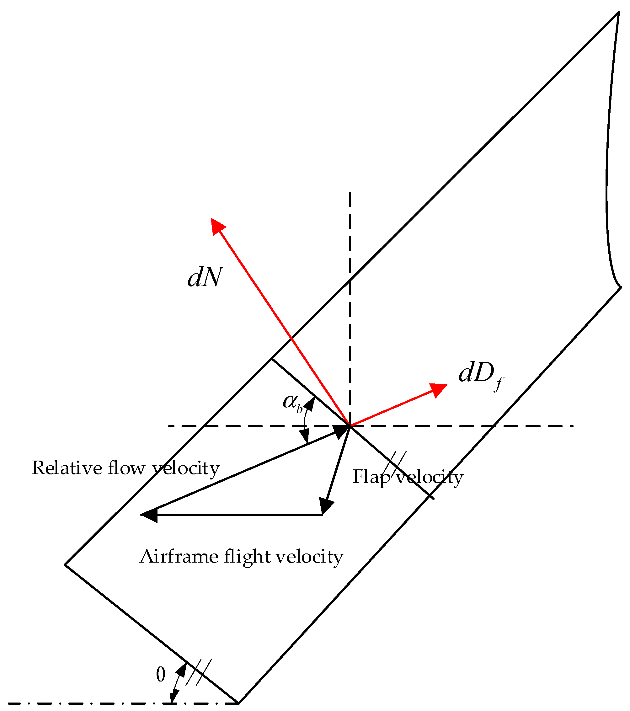
According to the unsteady aerodynamic force, the lift and drag generated by the unit length of the airfoil are
In the above formula, the aerodynamic lift dN is perpendicular to the direction of the relative incoming flow, and the direction of the aerodynamic drag dDf of the airfoil per unit length is in the same direction as the direction of the relative incoming flow. V is the airflow velocity and is the air density at standard atmospheric pressure. Dickinson simulated the aerodynamic characteristics and calculated the aerodynamic parameters CL and CD. From this, the calculation formulas of and the lift and drag coefficients CL and CD, respectively, were obtained as follows:
According to the spatial geometric position relationship, dN and dDf are decomposed along the z-axis and y-axis of the bat-like flapping robot coordinates, and the aerodynamic lift and aerodynamic thrust Fl and Ft generated by the strip during flapping are obtained:
In this formula, is the actual attack angle of the bat-like flapping aircraft and is the angle between the leading edge of the wing and the horizontal plane when flapping. The initial angle of attack of the bat-like flapping aircraft is and the actual flight angle of attack when considering the flexible deformation of the wing trailing edge is the vector sum of the initial angle of attack and the chordwise torsion angle , such that
As shown in Figure 3 and Figure 4, for the force analysis of the bat-like flapping aircraft during flapping, this article divides the flapping process into two stages: up-flapping and down-flapping. The complete stroke of the wing flapping phase of the bat-like flapping aircraft is from the highest position of the wing to the lowest position. During this process, the wing flaps downward around the wing root, generating upward aerodynamic force, which can be decomposed into vertical upward aerodynamic forces, namely lift, and horizontal forward thrust. When the bat-like flapping aircraft flies forward, the relative airflow velocity experienced by the wingspan section is the sum of the flapping speed and the fuselage flight speed. The angle between the wingspan section and the horizontal direction is the flapping angle . The angle relative to the direction of the incoming flow velocity is the flight angle of attack of the wings. Under the influence of airflow, the wing will produce aerodynamic lift dN and drag dDf, which are decomposed in the horizontal and vertical directions. The down-flapping phase of the wings provides most of the lift and thrust required for ornithopter flight.
According to the biological characteristics of bat wings, the wings of the bat-like flapping aircraft designed in this article are flexible wings, which are characterized by rigid leading edges and flexible trailing edges. We assume that during the flapping process of the wing, the angle between the leading edge and the horizontal plane is , and the angle between the trailing edge and the airfoil after deformation is , which is the chordwise torsion angle of the wing. The magnitude of the chordwise twist angle is related to the angular velocity of the wing’s swing. When the wing swings up and down to the maximum angle, the angular velocity is 0. At this time, . The swing amplitude of the bat-like flapping aircraft designed in this article is 60°, and the upward shot is 45°. If the shot is 15° downward, the expression of the maximum chordwise twist angle between and the trailing edge of the wing is
Based on the wing bar design, we can estimate that the spanwise transformation of the chordwise torsion angle from the wing root to the wing tip is linear. The twist angle at the wing root generally does not change, so we can estimate that the twist angle here is , and the wing tip is the location with the largest deformation, so the wing tip twist angle . We establish the chordwise twist angle as a function of time and spanwise coordinates:
In this formula, y is the coordinate of the tiny strip, and the direction is the span direction.
Combined with Equation (4), the aerodynamic force of the tiny strip is integrated with the spanwise coordinate y. The bat-like flapping aircraft designed in this article has a symmetrical design, so the functional relationship between the total aerodynamic lift and the total aerodynamic thrust and time is
Simulating the aerodynamic lift and aerodynamic thrust of the bat-like flapping-wing aircraft, Figure 5 is obtained, and the basic parameters are selected, as shown in Table 1.
In Figure 5a, we can observe the changes in the lift and thrust of the wing. In one cycle, the thrust generated by the wing presents two wave peaks. This is because, in one cycle, the wing swings up and down, reaching the maximum angle. The angle amplitude is different, so the maximum thrust generated will also be different. The generation of lift is the same, but the difference is that the lift has positive and negative values. The lift generated by the wing is negative when shooting down and positive when shooting up. At the same time, we can see that when the wing stops swinging, the lift value is 2. This is because the initial angle of attack will generate upward lift when there is relative flow, which is similar to the case of fixed wings.
2.2. Tail Deformation Aerodynamic Model
The bat-like flapping aircraft designed in this article, in addition to the lift and thrust generated by the flapping of the wings, also has pitch and roll moments provided by the tail. In this section, we analyze how the tail affects the attitude of the bat-like flapping aircraft.
As shown in Figure 6, the tail consists of two servos with two degrees of freedom. Servo a controls the pitch angle of the tail, similar to the elevator of a fixed-wing aircraft. Servo b controls the roll angle of the tail, similar to a rudder. Changes in the position of the tail will produce a three-dimensional moment relative to the fuselage, thereby changing the attitude of the fuselage, thereby achieving the purpose of changing the flight path.
During flight, the tail will be affected by the combined speed of the entire aircraft’s flight speed V and the incoming flow speed V(t) generated by wing flapping. However, the tail of the bat-flying flapping aircraft designed in this article is small, so it can be ignored. Thus, the incoming flow velocity Vw experienced by the tail is
We decompose the aerodynamic force generated by the tail wing into , and along the X, Y, and Z axes.
When the bat-like flapping-wing aircraft is flying, the tail is affected by the airflow [19], producing an aerodynamic force that rotates 90° in the return volume:
The aerodynamic force acting on the bat-like flapping aircraft produces a moment that can be decomposed on the three axes of the coordinate system:
Combining Equations (14)–(16), we can obtain the relationship between the tail moment and the tail attitude angle:
Via numerical simulation software(MATLAB2021b), we can intuitively observe the relationship between the roll moment Lx, the pitch moment Ly, the yaw moment Lz, the tail roll angle , and the pitch angle . According to the values in Table 1, the air density is under standard atmospheric pressure. Let the value range of the tail roll angle and pitch angle be .
In Figure 7, it can be seen that the change in the tail attitude angle affects the three-dimensional moment of the tail. Therefore, during the flight of the bat-like flapping aircraft, the aircraft can be controlled to complete climbs, turns, and other actions by changing the position of the tail.
When the tail roll angle is , changing the pitch angle will affect the pitching moment but will not affect the yaw moment and roll moment. In Figure 8, we can see that during the flight of the bat-like flapping aircraft, when the roll angle is kept at 0, changing the pitch angle of the tail can adjust the pitch attitude of the bat-like flapping aircraft, thereby achieving the purpose of adjusting the flight altitude.
By conducting aerodynamic modeling of the wings and tail of the bat-like flapping aircraft, the forces on the aircraft were established. Next, we conduct an overall aerodynamic lift and drag analysis on the rigid swing and tail deformation of the bat-like flapping aircraft based on strip theory. Since the stress situation of a bat-like ornithopter is more complicated during actual flight, we make several assumptions:
- (1)
- We ignore the influence of disturbing airflow in other directions than the relative incoming flow;
- (2)
- We ignore the impact of attitude changes on the aerodynamic force of the wing or tail during flight;
- (3)
- We treat the flapping of the wings and the movement of the tail as internal movements and ignore the influence of inertial forces;
- (4)
- We ignore the effect of atmospheric density changes caused by flight altitude and the effect of the Earth’s curvature caused by flight distance.
3. Aerodynamic Analysis of the Bat-Imitation Flapping-Wing Aircraft
This section takes the prototype of the bat-like flapping aircraft shown in Figure 9 as the research object, obtains the shape and motion parameters of the bat wing, and calculates the aerodynamic coefficients and aerodynamic derivative coefficients of the bat-like flapping aircraft.
The basic flight speed of the bat-like ornithopter prototype in this article is 13 m/s. In Table 2, SP is the distance between the two wing tips when the wings of the bat-like aircraft prototype are fully extended. C is the average chord length. AR is the aspect ratio, which is defined in this article as . Q is the bat wing load per unit area, defined as , where m is the mass of the bat, and S is the area of the bat-imitation flapping-wing aircraft prototype when its wings are fully extended.
When the flying speed of the bat-like ornithopter is U = 13 m/s, the average lift required to balance the body is .
In the above formula, is the air density. This article takes to obtain .
3.1. Rigid Swing Aerodynamic Response
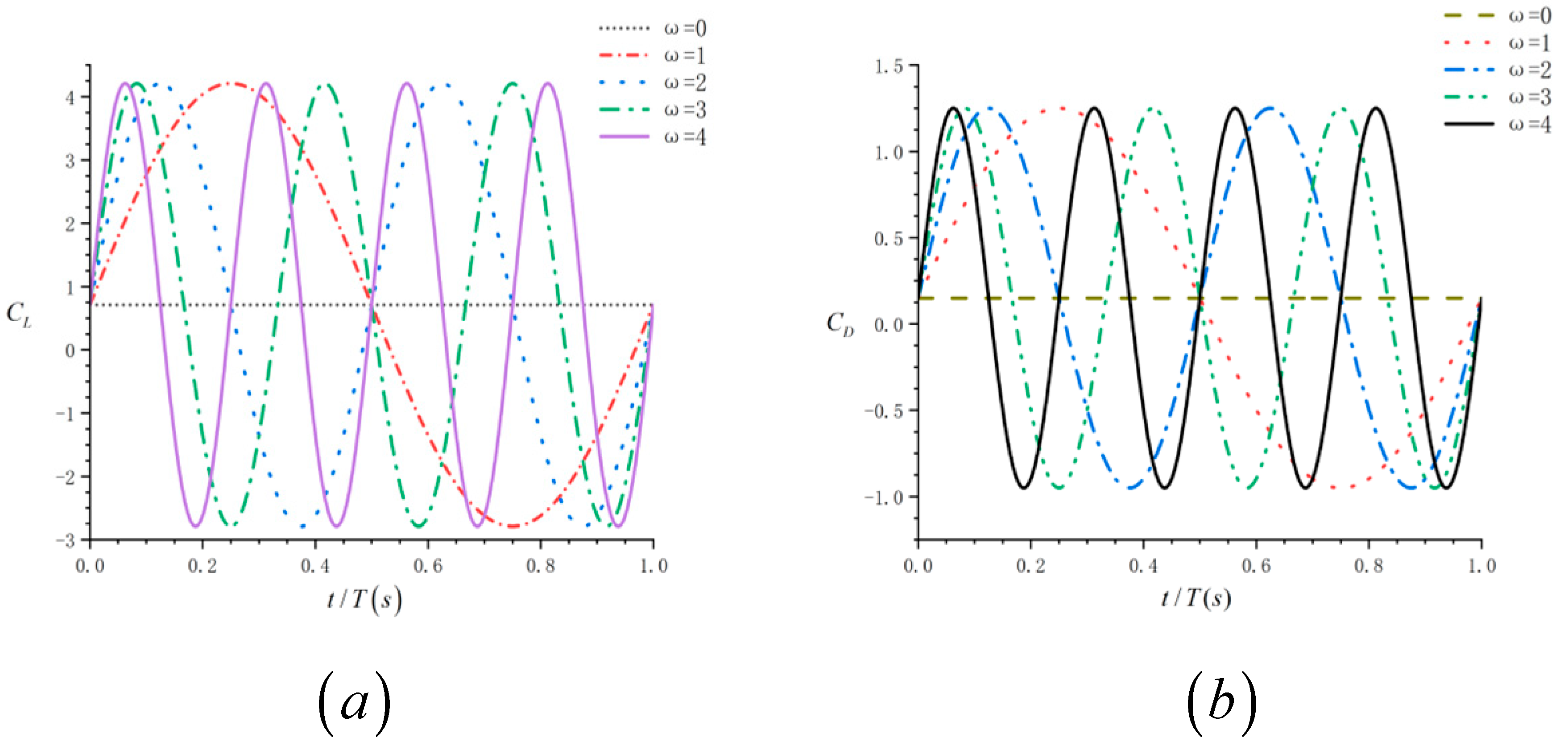
In this paper, we select the rigid swing mode with constant amplitude and variable frequency as the driving mode of the bat-like flapping aircraft. The calculation parameters are selected from the values in Table 2. Let , and increases from 0 to 4. It is clear that when , it corresponds to the fixed wing situation.
In Figure 10, we can see that, when (i.e., a fixed wing), the lift coefficient and drag coefficient are 0.71 and 0.15, respectively. The increase in will not affect the aerodynamic amplitude of a single stroke (one upbeat + downstroke) but will increase the number of strokes per unit of time—that is, the average lift and drag coefficients per unit of time increase with the increase in (Figure 10c). In general, as increases, the rigid swing increases the average aerodynamic lift and aerodynamic drag in the cycle, and the lift increases faster than the drag.
3.2. Aerodynamic Response of Tail Wing Pitch Angle
In a previous article, we proposed the aerodynamic model of the tail pitch angle. According to Equation (17), we know that the parameters that control the aerodynamic response of the tail pitch angle are the tail pitch angle and the tail roll angle . When the tail roll angle , changing the tail pitch angle can change the pitching moment of the tail. Next, the aerodynamic response of the tail pitch angle is analyzed by changing .
It can be seen from Figure 11 that as gradually increases, the peak lift coefficient decreases at (i.e., the upswing stage); at (i.e., the downswing stage), the lift coefficient increases. Therefore, we can conclude that as theta increases, the lift curve gradually flattens during a single swing stroke. The average lift increases as increases. However, when , the average lift coefficient increases slowly without significant change. When , the average lift coefficient begins to decrease. In this article, the pitch angle of the tail of the bat-like flapping aircraft is mainly used to change the pitch attitude of the aircraft. When the pitch angle is too large, the angle of attack of the aircraft will also become larger, the aircraft will enter a stall state, and the lift coefficient will suddenly become smaller. Considering that there are various airflow disturbances in actual flight, we limit the tail angle and pitch angle of the bat-like flapping aircraft to between −30° and 30°.
4. Design of Longitudinal Channel Controller for a Bat-like Ornithopter
In our previous article, based on the morphological parameters of the prototype, we analyzed the aerodynamic response of the rigid swing and the aerodynamic response of the tail pitch angle of the bat-like flapping aircraft. In this section, we conduct kinematic and dynamic modeling of the designed bat-like flapping aircraft based on the previous force analysis and design a pitch angle controller oriented to the longitudinal channel.
4.1. Kinematic and Dynamic Modeling
According to Newton’s law, a system of force and moment equations of the bat-like flapping aircraft is established:
The dynamic equations are as follows:
In the formula, Fx, Fy, and Fz are the components of the force on the three axes of the body of the bat-like flapping aircraft, L, M and N are the moments of the three axes, respectively. Ix, Iy, and Iz are, respectively the moment of inertia of the body about the three axes XYZ, Ixz is the inertial product of the cross-section XZ with respect to the centroid of the body, and other variables are shown in Table 3.
During flight, the equation of the force exerted on the bat-like flapping aircraft can also be expressed as
According to Equations (19) and (21), we can get the equations of the forces in three directions on the bat-like flapping aircraft:
It can be seen from Equations (20) and (21) that the main factors related to the longitudinal direction of the aircraft are as follows:
The following is related to the lateral direction of the aircraft:
In Formulas (22) and (23), the definitions of each variable are shown in Table 4.
In Table 4, the quantity with a subscript represents the incremental coefficient of the variable with the same name as the subscript. For example, for the thrust increment, according to the aerodynamic modeling of the wing in the second part of this article, we know that the thrust is mainly affected by the flapping frequency and speed of the wing. Since the bat-like flapping aircraft designed in this article is Flying at low altitudes, some aerodynamic effects caused by changes in air density caused by altitude can be ignored. From this, we can obtain the expressions of various forces and moments, as shown in Table 4.
In order to facilitate the solution, the longitudinal equations of Equation (22) are normalized to obtain Equation (24).
From Equation (21), a state space equation of the form can be established, where
In Equations (25) and (26), each element in the matrix is composed of aerodynamic derivatives and aerodynamic coefficients. The specific expressions are in Table 5. In terms of aerodynamic coefficients, each element in A is related to the lift coefficient CL, the drag coefficient CD, and the pitching moment coefficient CM. In terms of aerodynamic derivatives, , , and are related to the derivatives of lift L and pitching moment with respect to velocity . , , and are related to the derivatives of lift L, pitching moment M, and drag D with respect to velocity w. is related to the derivative of lift L, pitching moment M, and drag D with respect to the pitching angular velocity q. Each element in the matrix B is a manipulation derivative. , , are related to the lift L and pitching moment M to the tail pitch angle deformation . , are related to the lift force L and the pitching moment M to the rigid swing frequency :
4.2. System Stability Analysis
The most important control variable of the longitudinal control channel of the flapping-wing aircraft is the pitch angle. The flapping-wing aircraft must maintain a certain pitch angle to provide sufficient lift during takeoff, forward flight, landing, etc. By adjusting the change in the pitch angle of the flapping-wing aircraft, the steady-state aerodynamic moment can be affected, thereby controlling the movement attitude of the flapping-wing aircraft.
The Laplace transform of Equation (21) is
The characteristic polynomial of the system is
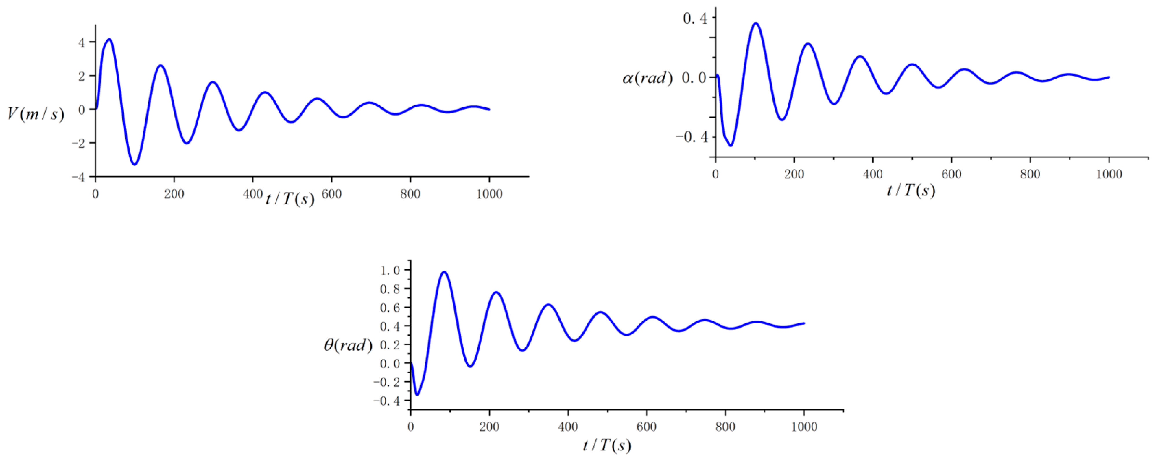
In the reference flight state, a pulse disturbance signal is given to the angle of attack, and the open-loop response of the bat-like flapping aircraft is shown in Figure 12.
As shown in Figure 12, after a pulse disturbance signal is given to the angle of attack, V, , and all oscillate in a short period of time. After a period of time, the three state quantities gradually become stable. This shows that the system of the bat-like flapping aircraft designed in this article is statically stable and controllable, which is also the basis for designing the controller.
From the perspective of the pitch control loop, although the system finally approaches stability, the adjustment time is too long, and the overshoot is large. It is obvious that the system is an under-damped system with insufficient damping and needs to be improved. According to the aerodynamic characteristics of the bat-like flapping aircraft, the longitudinal short-period damping ratio mainly depends on the longitudinal damping moment derivative Mq. The value of Mq exactly reflects the value of the aircraft’s own pitch-damping moment . Therefore, a pitch angle rate feedback loop needs to be introduced to increase the pitching moment, thereby improving the damping ratio of the aircraft’s short-period motion.
4.3. Longitudinal Pitch Angle Control Based on LQR
LQR is the linear quadratic optimal controller. Its research object is a linear system described by state space. The weight matrices Q and R of the linear system uniquely determine the state feedback matrix K of the system to achieve an optimal input signal u. The quadratic performance index function J reaches the minimum, thereby obtaining the best performance index.
The longitudinal control loop of the bat-inspired flapping-wing aircraft mainly realizes pitch angle and height control. The inner loop controls the pitch angle, and the outer loop realizes height control. The inner loop pitch angle control stabilizes the pitch angle attitude of the bat-inspired flapping-wing aircraft at the desired value by changing the tail and chordwise deformation.
In the initial stage of the longitudinal motion of the flapping-wing aircraft, the incremental changes in airspeed and pitch angle are not large. Assuming that at this time, the longitudinal state space equation of the bat-like flapping-wing aircraft is simplified as follows:
The state space equation is established as follows:
The design control rate is as follows:
where K is the feedback gain matrix and the steady-state state and steady-state input satisfy
We invert matrix (30) to obtain
The control rate design principle based on state feedback is shown in Figure 13.
In order to meet the system control rate requirements, we need to configure a suitable feedback matrix K. Next, we solve the feedback matrix K via the LQR method.
The necessary and sufficient condition for the stability of the feedback system is that all poles of the system’s closed-loop transfer function have negative real parts—that is, they are all located on the left side of the S plane in the complex frequency domain, achieved by configuring the K matrix so that the eigenvalues (poles) of matrix all have negative real parts. Next, we use the LQR method to solve for K.
Here, we introduce the cost function J to make the system converge while minimizing J:
where t0 and tf are the control start and end times, respectively. Both Q and R are positive semi-definite matrices set by the user.
We assume that the system is in a stable state, and the state feedback is .
Substitute the state equation into the cost function J.
Suppose there exists a constant matrix P, such that
Differentiate both sides of Equation (36) to obtain
Substitute the state equation into Equation (37).
The conditions for the above formula to hold are as follows:
This is further simplified to
Take and substitute it into the above equation to obtain the equation:
According to P, the feedback matrix can be calculated.
The design principle of the system’s state feedback control rate based on LQR is shown in Figure 14:
In this article, the equation for the pitch angle state is as follows:
The feedback gain matrix is as follows:
In order to meet the above control rate scheme, the system must meet the following two assumptions:
- (1)
- The system is reversible (m = p), stable, and has no variable zero at the origin.
- (2)
- The system has at least n − 2p different LHP zero points.
Solving the above state space equation, the zero and pole points of the system are , , , and . As shown in Figure 15, the characteristic roots of the system are all located in the left half of the s-plane—that is, each characteristic root has a negative real part, so the system is stable. Obviously, there are n − 2p = 2 LHP zero points, and the system satisfies assumptions 1 and 2.
5. Simulation and Flight Test
In previous sections, we established the dynamic and kinematic equations based on the bat-like flapping aircraft and designed a pitch angle controller based on LQR on this basis. In this section, we conduct a simulation analysis of the controller and use the designed simulation. The bat flapping-wing aircraft prototype was subjected to a real-life flight experiment to verify the feasibility of this design.
5.1. Simulation Analysis
First, we conducted experiments on pitch angle control to ensure that the system’s pitch angle control meets the design requirements, and then conducted an altitude control simulation. The altitude control of the bat-like flapping aircraft is mainly controlled via the pitch angle.
The effectiveness of the algorithm was verified via digital simulation, and a pitch angle tracking experiment was performed. This experiment required that the bat-like flapping-wing aircraft be able to track the expected value input over time and cause the steady-state value of the pitch angle output to finally stabilize at the expected value.
- The expected value of the pitch angle is given as .
- The dynamic expected pitch angle values are given , , , ,
As shown in Figure 16 and Figure 17 that the pitch angle controller of the bat-inspired flapping-wing aircraft can quickly track the pitch angle without overshooting the system.
From the simulation of the system, the system improved by the LQR controller has no overshoot in the output and a shorter adjustment time than the system before the controller is applied. The damping ratio of the system is calculated to be , which is an over-damped system. For a system such as a flapping-wing aircraft that moves periodically in the pitch direction, over-damping can well ensure the stability of the pitch control loop.
5.2. Altitude Control
There is a coupling problem between the longitudinal flight trajectory control and the speed control of the bat-like flapping wing aircraft. The total energy control system [20,21] uses the mutual conversion relationship between the kinetic energy and potential energy of the bat-like flapping wing aircraft to establish that when the power is balanced, the total energy of the bat-like flapping wing aircraft remains unchanged, and the tail is used to control the distribution relationship between kinetic energy and potential energy to achieve rapid stability and control of speed/altitude.
The total energy of the bat-inspired flapping-wing aircraft is composed of kinetic energy and potential energy, expressed as the following formula:
During flight, the thrust required by the bat-inspired flapping-wing aircraft is
After being disturbed, the required thrust increment is proportional to the product of and flight weight (G = mg):
Considering Formula (44), the total energy per unit weight of the bat-inspired flapping-wing aircraft can be expressed as
From Formulas (44) and (47) can become
Substituting (45),
The above equation shows that, during the flight phase of the bat-inspired flapping-wing aircraft, changes in total energy are mainly controlled by changes in thrust. In level flight, the initial thrust is used to offset the drag, so the control effect of the thrust increment is
Among them, represents the thrust change amount, and the subscript e represents the parameter deviation. From Formulas (48) and (50), we can obtain
represents the deviation of the total energy change rate of the bat-inspired flapping-wing aircraft. Therefore, when the thrust of the bat-inspired flapping-wing aircraft changes, it also changes the energy change rate at a certain rate—that is, the sum of the acceleration of the bat-inspired flapping-wing aircraft and the pitch angle of the flight path changes. Based on this, the control rate of the total energy change of the bat-inspired flapping-wing aircraft can be designed as follows:
5.3. Altitude Control Simulation Analysis
When the bat-inspired flapping-wing aircraft flies at a height of 25 m, given the system has a height expectation of 45 m, we can conduct a simulation analysis.
We can see from the Figure 18 that, after the introduction of altitude control, the system can quickly keep up with expectations in a short period of time and quickly return to a stable state.
5.4. Flight Test
In order to verify the reliability of the previous theoretical analysis, we conducted an outdoor flight test. The bat-like flapping aircraft used in this test is shown in Figure 9 and was produced by the team.
The driving mode of the bat-like flapping-wing aircraft is a double crank and double rocker structure, as shown in Figure 19. The design of the driving mode directly determines the flight performance and flight attitude of the bat-like flapping-wing aircraft. At present, there are four main flapping mechanisms, namely a single crank and double rocker structure, a double crank and double rocker structure, a crank slider structure, and a cam transmission structure. Compared with the crank slider, cam transmission, and single crank rocker structures, the double crank and double rocker structures used in this article have the advantages of strong structural stability, moderate production complexity, and high transmission efficiency.
The fuselage of the bat-like flapping aircraft was cut from carbon fiber plates. Among existing materials, carbon fiber has superior performance in terms of its strength and weight. At the same time, its secondary processing technology is mature, and the accuracy of commercial carbon fiber cutting machine tools can reach millimeter levels. Based on the strength and flight test results, this article selected a 1.5 mm thick carbon fiber plate as the fuselage of the bat-like flapping aircraft. As the main power-generating components of the bat-like ornithopter, the selection of wing cloth and wing rods is extremely important. The wing fabric needs to be light and thin while also having sufficient strength and airtightness. At the same time, considering the cost issue, this article selected P31N material. As the main rigid motion component of the bat-like flapping wing aircraft, the strength requirements of the wing bar are very important. At the same time, for the sake of the overall weight, its density cannot be too high. After comprehensively considering various factors, including cost, processing, etc., a hollow carbon fiber rod with a radius of 1 mm was selected as the wing bar.
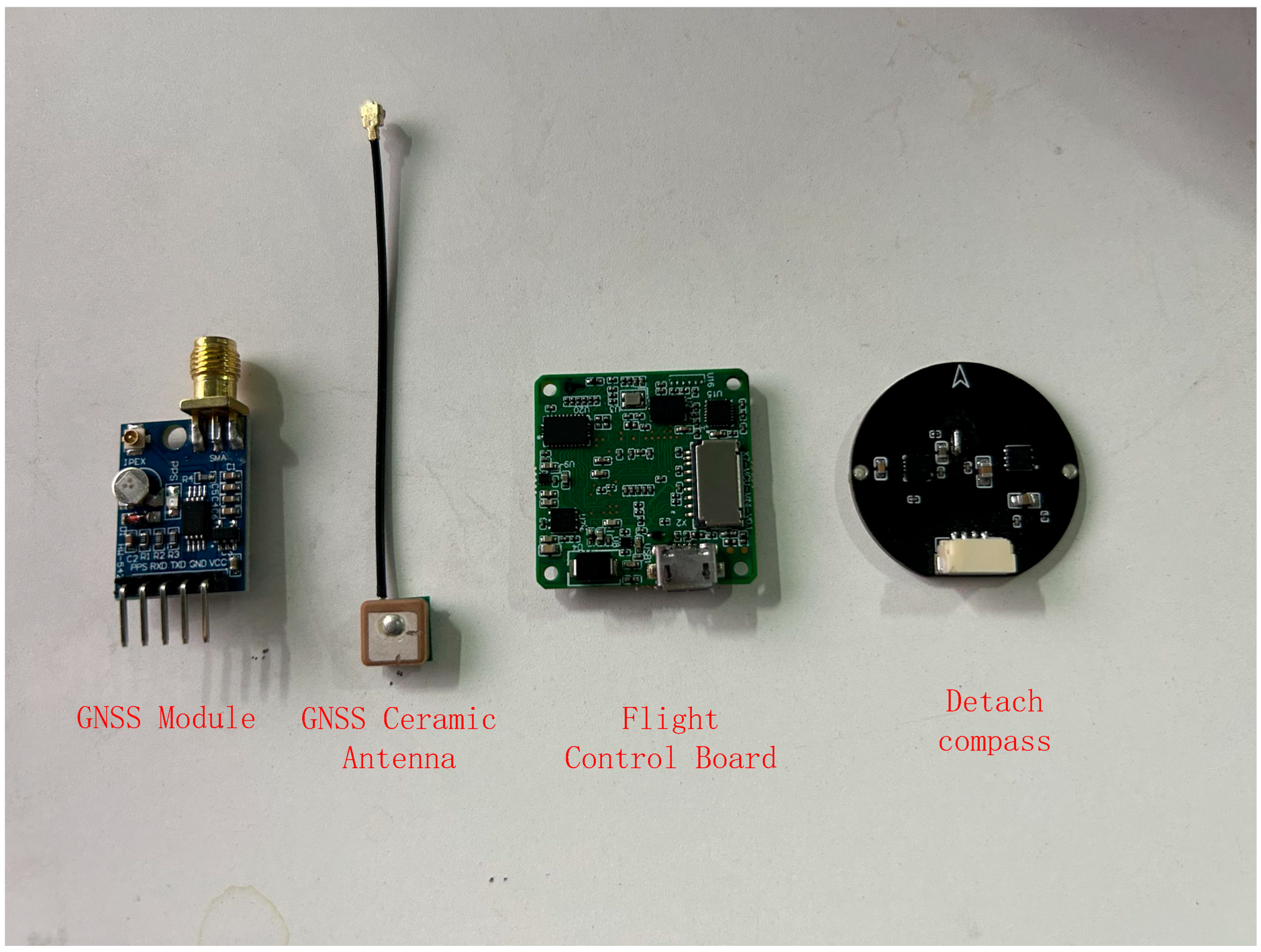
The flight control board of the bat-like flapping aircraft designed in this article was independently developed and equipped with STM32H7 series chips. The STM32H7 series chip is a high-performance 32-bit microcontroller based on the Arm Cortex-M7 core and integrates a wealth of peripherals and interfaces suitable for a wide range of application fields, including industrial control, automotive electronics, medical equipment, aerospace, etc. We integrated a high-precision barometer MS5611 and an inertial navigation module ICM20649 + BMI088. In order to avoid the interference of the integrated circuit board on the GNSS and compass, this article used a separate compass and GNSS (Figure 20).
The overall hardware of the bat-like flapping-wing aircraft adopts a lightweight design. The total weight of all electronic components does not exceed 9 g. The weight of the flight control board is only 4 g, and its shape is a square with a side length of 27.9 mm. The length of the GNSS module is 23.08 mm, and the width is 17.37 mm.
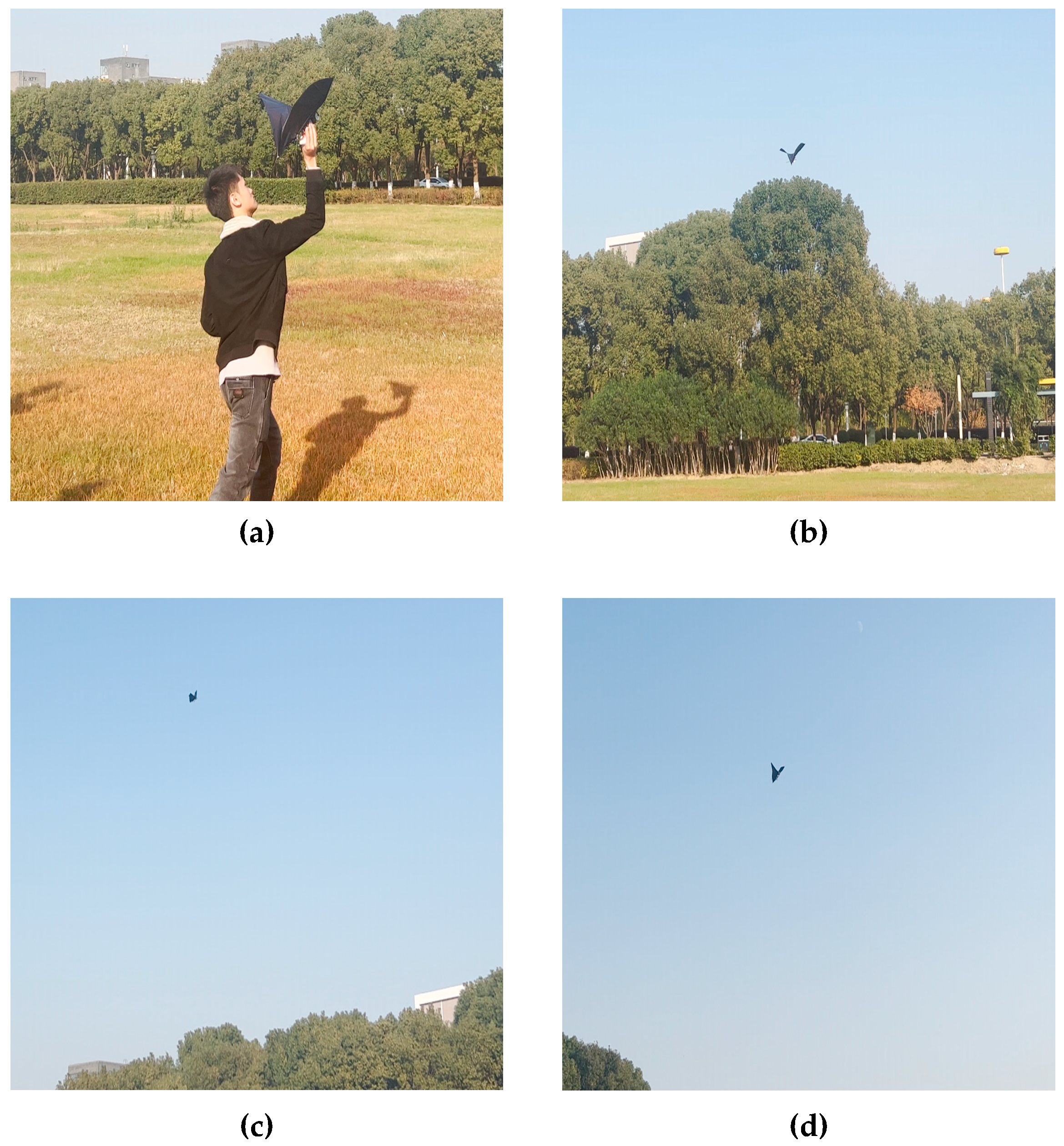
The flight test lasted for 50 min. The outdoor test verified the forward flight, climbing, turning, and other functions of the bat-like flapping wing aircraft. During the entire flight, the aircraft showed high controllability and stability. When climbing, the aircraft’s response time was shorter. When flying forward, the aircraft’s pitch stability converged. When the aircraft transitioned from turning to forward flight, its movement was very smooth and fast.
The four pictures in Figure 21 show the four flight states of the bat-like flapping-wing aircraft in this test. It can be seen from the figure that the bat-like flapping-wing aircraft begins to fly and quickly enters the climbing stage. When it reaches the desired height, the bat-like ornithopter begins to fly forward, and finally enters a turning state.
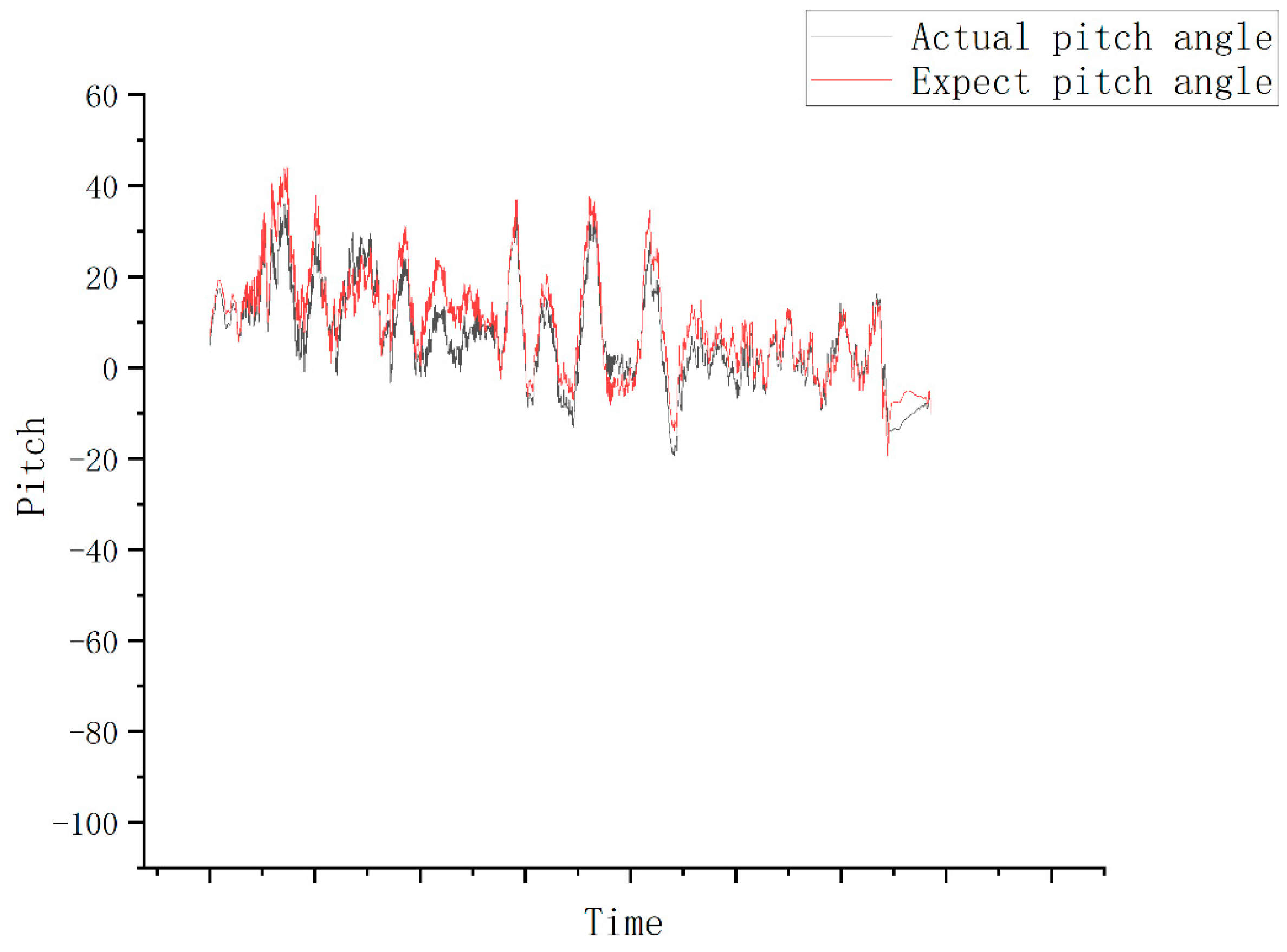
Figure 22 shows the tracking of the pitch angle in this test. The bat-like flapping-wing aircraft has an integrated wing-body structure similar to that of a bat. When using rigid swing as the main driving method, the axis direction of the aircraft will vibrate with every swing, which is reflected in the figure as the pitch angle. Regarding the high-frequency jitter, the red line in Figure 22 is the expected pitch angle, and the green line is the actual pitch angle measured by the sensor mounted on the bat-like flapping aircraft. It can be seen from the figure that the actual pitch angle of this test can track the expected pitch angle throughout the entire test, with fast response speed and no overshoot. However, it can also be seen that the pitch angle displays a large oscillation. Although the driving method has great advantages, the integrated wing structure requires improvement.
6. Conclusions
Bat-imitating flapping-wing aircraft are bionic flapping-wing aircraft that can be widely used in various types of military reconnaissance and agricultural and animal husbandry inspections. However, due to the unique flight mechanisms of bats and the unsteady dynamic characteristics of flexible wings, bat-imitating flapping-wing aircraft have limited uses. Their development is mostly in the theoretical stage, and there are very few examples of actual aircraft flying. This article proposed a design and production plan for a bat-like flapping aircraft. The fuselage structure was divided into the wings and tails. Considering the soft wing body structure of bats in nature, we approximately analyzed the effects of this flexibility during flight via strip theory. The aerodynamic effects of the deformation were produced in the flight of a bat-like ornithopter.
With the help of strip theory, we analyzed the aerodynamic lift and resistance of the entire aircraft. In order to facilitate the design of the controller, we derived the dynamic and kinematic equations of the bat-like flapping aircraft. The lightweight hardware design not only ensured reliable flight but also greatly reduced the weight of the aircraft. The double-crank rocker could complete the flapping of the two wings using one motor. These designs are all designed to reduce the weight of the aircraft and extend its endurance.
Both the simulation results and flight test results prove that the design of the bat-imitation flapping-wing aircraft is successful. This has great positive significance for the promotion and market popularization of bat-like ornithopters.
7. Future Work
In our future work, we will carry out the following tasks:
- (1)
- Completing the lateral channel modeling and controller design of our bat-like flapping aircraft;
- (2)
- Improving the airfoil shape and structure, adding a folding wing device, reducing the resistance in the upswing phase of the rigid swing, and increasing the overall lift in the cycle.
In addition, the passive deformation of the wing membrane during flight is an important feature of flexible wings. Studies have shown that passive deformation plays an important role in bat flight. The next step is to select suitable flexible materials for use in the aircraft.
Author Contributions
Conceptualization, F.W. and Y.B.; methodology, F.W. and X.P. validation, F.W. and X.P.; structure analysis, G.W.; investigation, F.W. and X.P.; resources, F.W.; data curation, F.W.; writing—original draft preparation, F.W.; writing—review and editing, Y.B.; visualization, F.W.; project administration, X.P.; funding acquisition, Y.B. and G.W. All authors have read and agreed to the published version of the manuscript.
Funding
This work is supported by the National Natural Science Foundation of China (No. 62303437), National Key R&D Program of China (No. 2022YFF1302000); the Innovation Guidance Fund Project of Innovation Academy for Light-duty Gas Turbine, CAS (No. CXYJJ20-ZD-03); and the Regional Development Young Scholars Program of the Chinese Academy of Sciences.
Data Availability Statement
The data presented in this study are available upon request from the corresponding author. Original data can be obtained by contacting the corresponding author.
Conflicts of Interest
The authors declare no conflicts of interest. The manuscript was written with the contributions of all authors. All authors have approved the final version of the manuscript.
References
- Sun, M. Aerodynamics of animal flight. Acta Aerodyn. Sin. 2018, 36, 122–128. [Google Scholar]
- Tanaka, H.; Okada, H.; Shimasue, Y.; Liu, H. Flexible flapping wings with self-organized microwrinkles. Bioinspiration Biomim. 2015, 10, 046005. [Google Scholar] [CrossRef] [PubMed]
- Riskin, D.K.; Willis, D.J.; Iriarte-Díaz, J.; Hedrick, T.L.; Kostandov, M.; Chen, J.; Laidlaw, D.H.; Breuer, K.S.; Swartz, S.M. Quantifying the complexity of bat wing kinematics. J. Theor. Biol. 2008, 254, 604–615. [Google Scholar] [CrossRef] [PubMed]
- Azuma, A. The Biokinetics of Flying and Swimming; Springer Science & Business Media: Berlin/Heidelberg, Germany, 2012. [Google Scholar]
- Yu, Y.; Guan, Z. Learning from bat: Aerodynamics of actively morphing wing. Theor. Appl. Mech. Lett. 2015, 5, 13–15. [Google Scholar] [CrossRef]
- Guan, Z.; Yu, Y. Aerodynamic mechanism of forces generated by twisting model-wing in bat flapping flight. Appl. Math. Mech. 2014, 35, 1607–1618. [Google Scholar] [CrossRef]
- Guan, Z.; Yu, Y. Aerodynamics and mechanisms of elementary morphing models for flapping wing in forward flight of bat. Appl. Math. Mech. 2015, 36, 669–680. [Google Scholar] [CrossRef]
- Joshi, V.; Jaiman, R.K.; Ollivier-Gooch, C. A variational flexible multibody formulation for partitioned fluid–structure interaction: Application to bat-inspired drones and unmanned air-vehicles. Comput. Math. Appl. 2020, 80, 2707–2737. [Google Scholar] [CrossRef]
- Fan, X.; Swartz, S.; Breuer, K. Power requirements for bat-inspired flapping flight with heavy, highly articulated and cambered wings. J. R. Soc. Interface 2022, 19, 20220315. [Google Scholar] [CrossRef]
- Wagter, C.D.; Tijmons, S.; Remes, B.D.W.; de Croon, G.C. Autonomous Flight of a 20-gram Flapping Wing MAV with a 4-gram Onboard Stereo Vision System. In Proceedings of the IEEE International Conference on Robotics & Automation, Hong Kong, China, 31 May–7 June 2014; IEEE: Piscataway, NJ, USA, 2014. [Google Scholar]
- Ramezani, A.; Shi, X.; Chung, S.-J.; Hutchinson, S. Bat Bot (B2), A Biologically Inspired Flying Machine. In Proceedings of the 2016 IEEE International Conference on Robotics and Automation (ICRA), Stockholm, Sweden, 16–21 May 2016; pp. 3219–3226. [Google Scholar]
- Hedrick, T.L.; Cheng, B.; Deng, X. Wingbeat time and the scaling of passive rotational damping in flapping flight. Science 2009, 324, 252–255. [Google Scholar] [CrossRef]
- Hoff, J.; Ramezani, A.; Chung, S.-J.; Hutchinson, S. Reducing Versatile Bat Wing Conformations to a 1-DoF Machine. In Proceedings of the Biomimetic and Biohybrid Systems 6th International Conference, Living Machines 2017, Stanford, CA, USA, 26–28 July 2017; pp. 181–192. [Google Scholar]
- Hoff, J.; Ramezani, A.; Chung, S.J.; Hutchinson, S. Optimizing the structure and movement of a robotic bat with biological kinematic synergies. Int. J. Robot. Res. 2017, 37, 1233–1252. [Google Scholar] [CrossRef]
- Ramezani, A.; Chung, S.J.; Hutchinson, S. A biomimetic robotic platform to study flight specializations of bats. Sci. Robot. 2017, 2, eaal2505. [Google Scholar] [CrossRef] [PubMed]
- Bahlman, J.W.; Swartz, S.M.; Breuer, K.S. Breuer Design and characterization of a multi-articulated robotic bat wing. Bioinspiration Biomim. 2013, 8, 016009. [Google Scholar] [CrossRef] [PubMed]
- Bunget, G. BATMAV—A Bio-Inspired Micro-Aerial Vehicle for Flapping Flight; The Graduate Faculty of North Carolina State University: Raleigh, NC, USA, 2010. [Google Scholar]
- Zhang, X.; Zhou, C. Numerical Investigation on the Aerodynamic Characteristics of a Forward Flight Flapping Airfoil with Nonsymmetrical Plunging Motion. Inf. Technol. J. 2011, 10, 258–266. [Google Scholar]
- Dickinson, M.H.; Lehmann, F.O.; Sane, S.P. Wing rotation and the aerodynamic basis of insect flight. Science 1999, 284, 1954. [Google Scholar] [CrossRef]
- Lambregts, A.A. TECS Generalized Airplane Control System Design–An Update, Advances in Aerospace Guidance, Navigation and Control: Selected Papers of the Second CEAS Specialist Conference on Guidance, Navigation and Control; Springer: Berlin/Heidelberg, Germany, 2013; pp. 503–534. [Google Scholar]
- Wu, S.; Guo, S. Optimum flight trajectory guidance based on total energy control of aircraft. J. Guid. Control Dyn. 1994, 17, 291–296. [Google Scholar] [CrossRef]
- Warkentin, J.; DeLaurier, J. Experimental aerodynamic study of tandem flapping membrane wings. J. Aircr. 2007, 44, 1653–1661. [Google Scholar] [CrossRef]
- Zakaria, M.Y.; Taha, H.E.; Hajj, M.R. Design optimization of flapping ornithopters: The pterosaur replica in forward flight. J. Aircr. 2016, 53, 48–59. [Google Scholar] [CrossRef]
- Zakaria, M.Y.; Allen, D.W.; Woolsey, C.A.; Hajj, M.R. Lift and drag of flapping membrane wings at high angles of attack. In Proceedings of the 34th AIAA Applied Aerodynamics Conference, Washington, DC, USA, 13–17 June 2016; p. 3554. [Google Scholar]
Figure 1.
(a) Schematic diagram of a rigid swing. (b) Rigid swing amplitude changes.
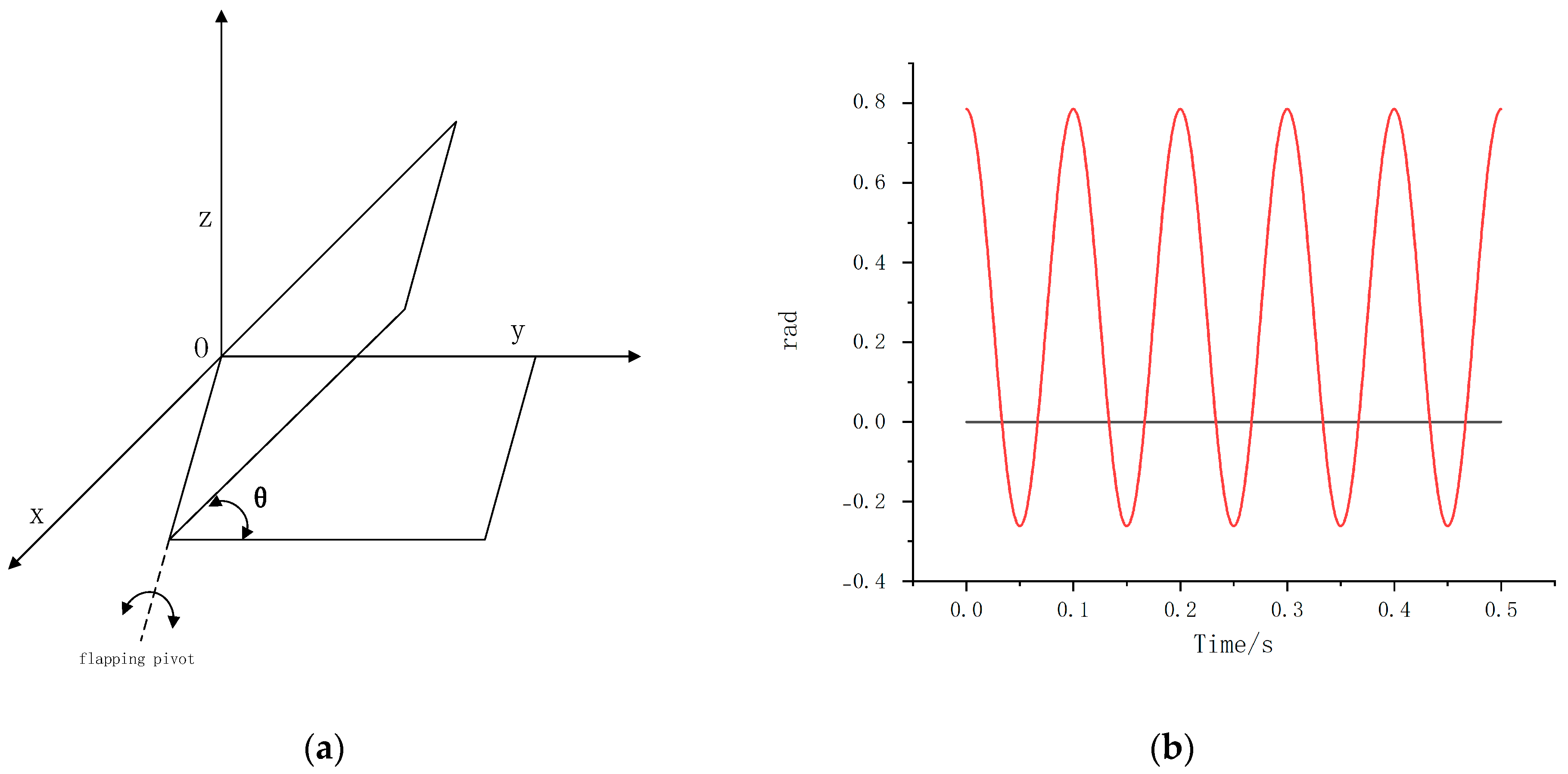
Figure 2.
Simplified plane of a bat-like wing.
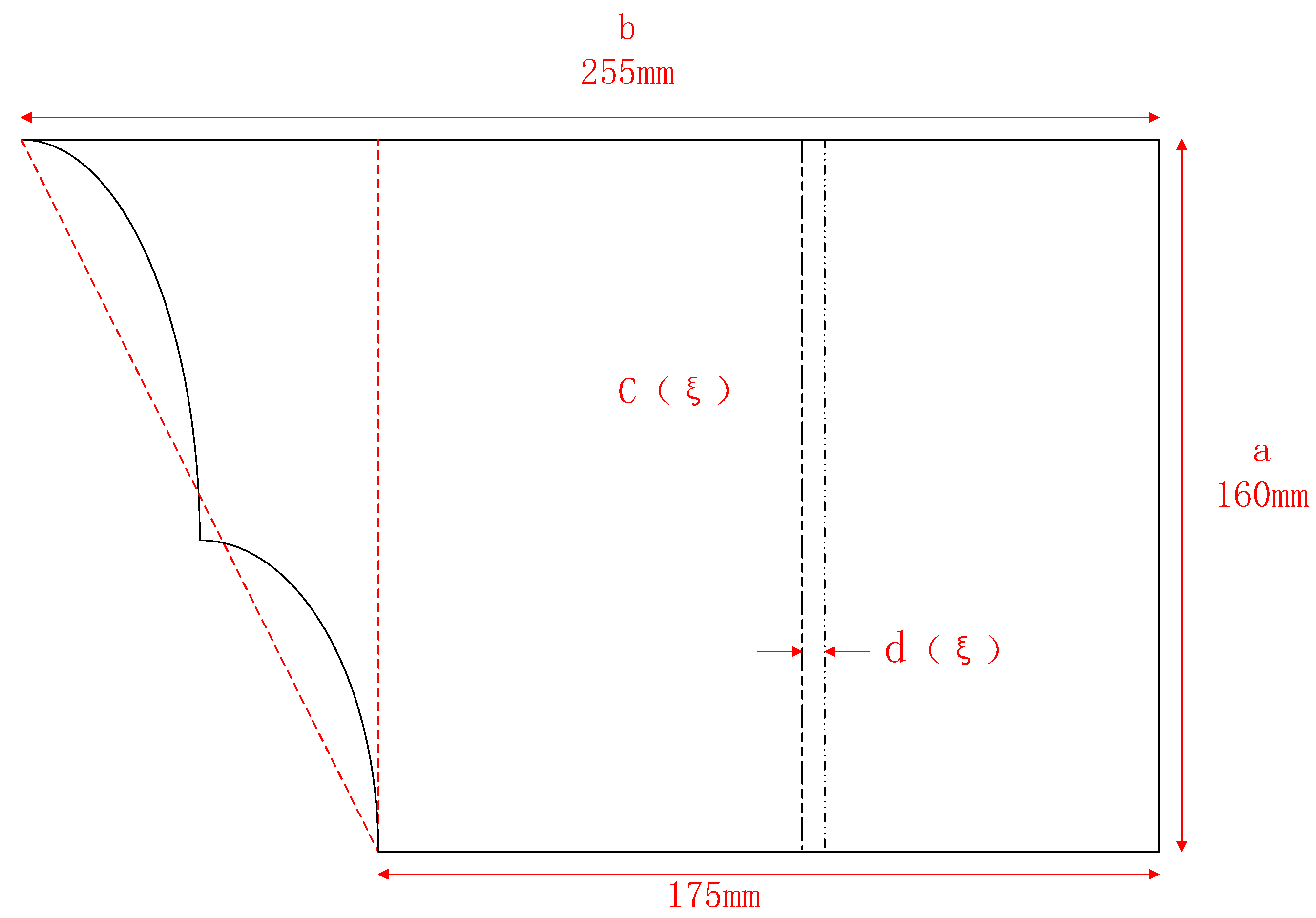
Figure 3.
Wing-up shot diagram.

Figure 4.
Wing downswing diagram.
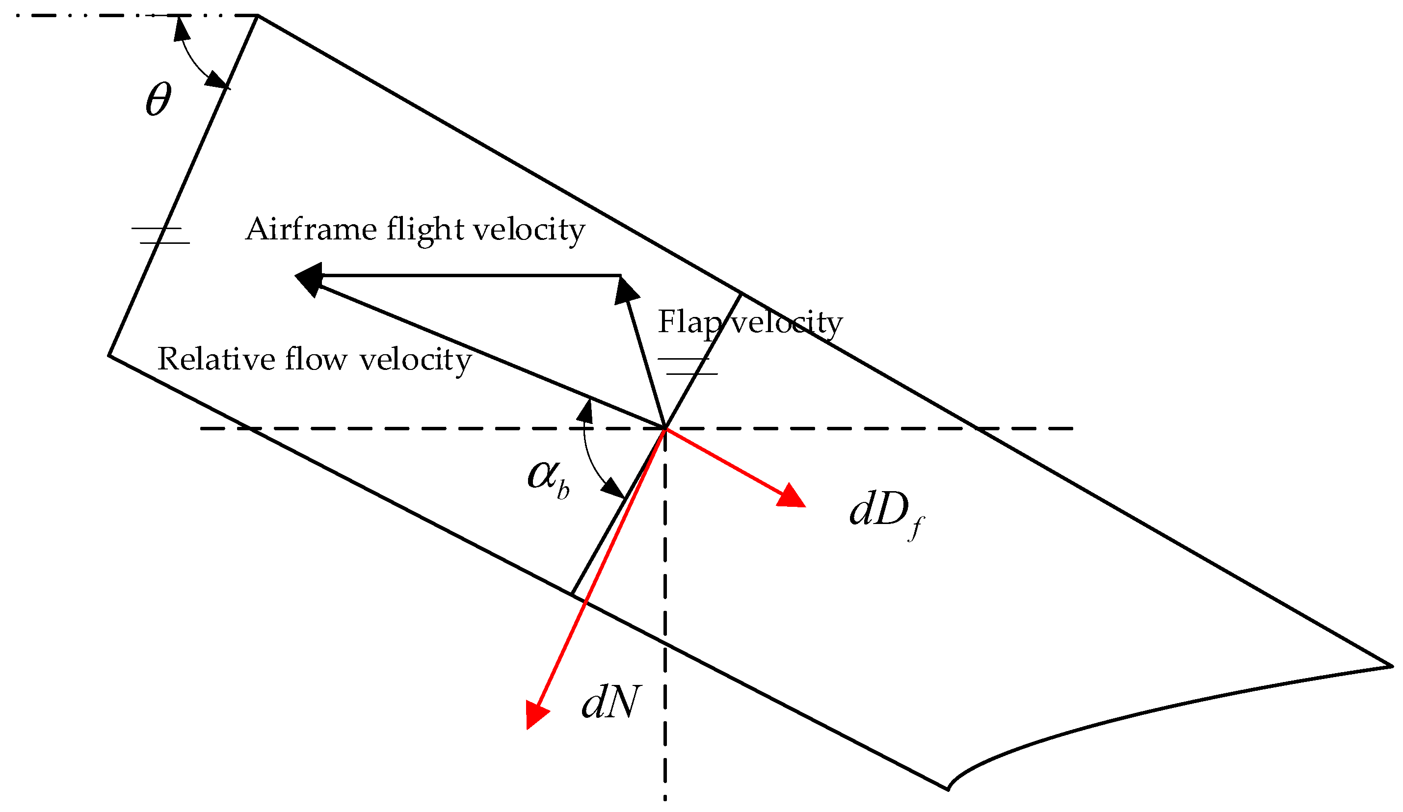
Figure 5.
(a) Relationship between wing aerodynamic lift, time t and the spanwise coordinate y. (b) Relationship between wing aerodynamic thrust, time t, and the spanwise coordinate y.
Figure 5.
(a) Relationship between wing aerodynamic lift, time t and the spanwise coordinate y. (b) Relationship between wing aerodynamic thrust, time t, and the spanwise coordinate y.
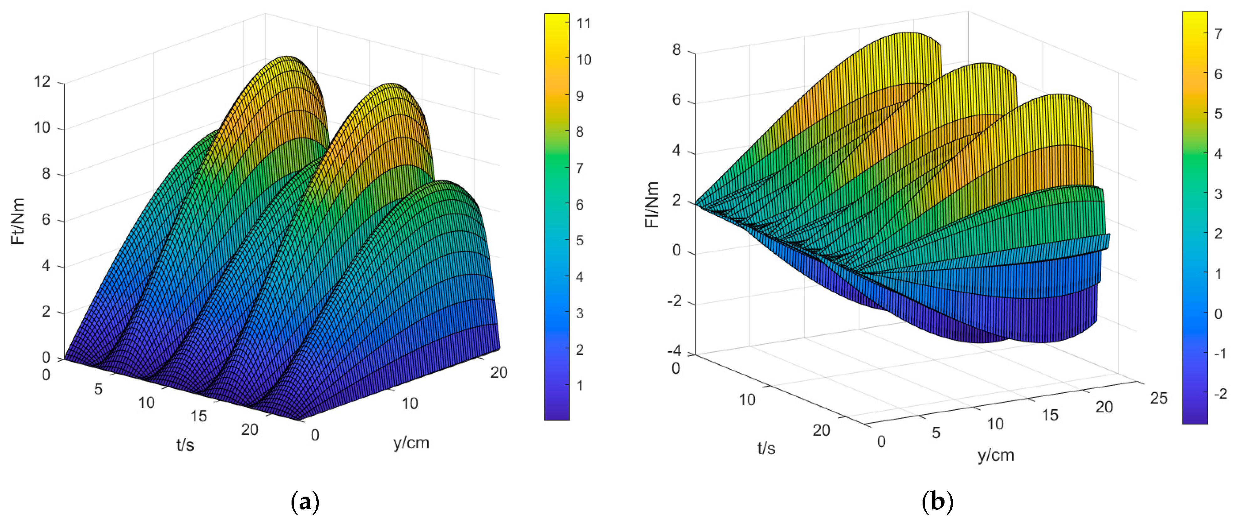
Figure 6.
Bat-like ornithopter single-side tail (① and ② are servos, ① completes the roll deformation of the tail by controlling ④, and ② completes the pitching deformation of the tail by controlling ③).
Figure 6.
Bat-like ornithopter single-side tail (① and ② are servos, ① completes the roll deformation of the tail by controlling ④, and ② completes the pitching deformation of the tail by controlling ③).
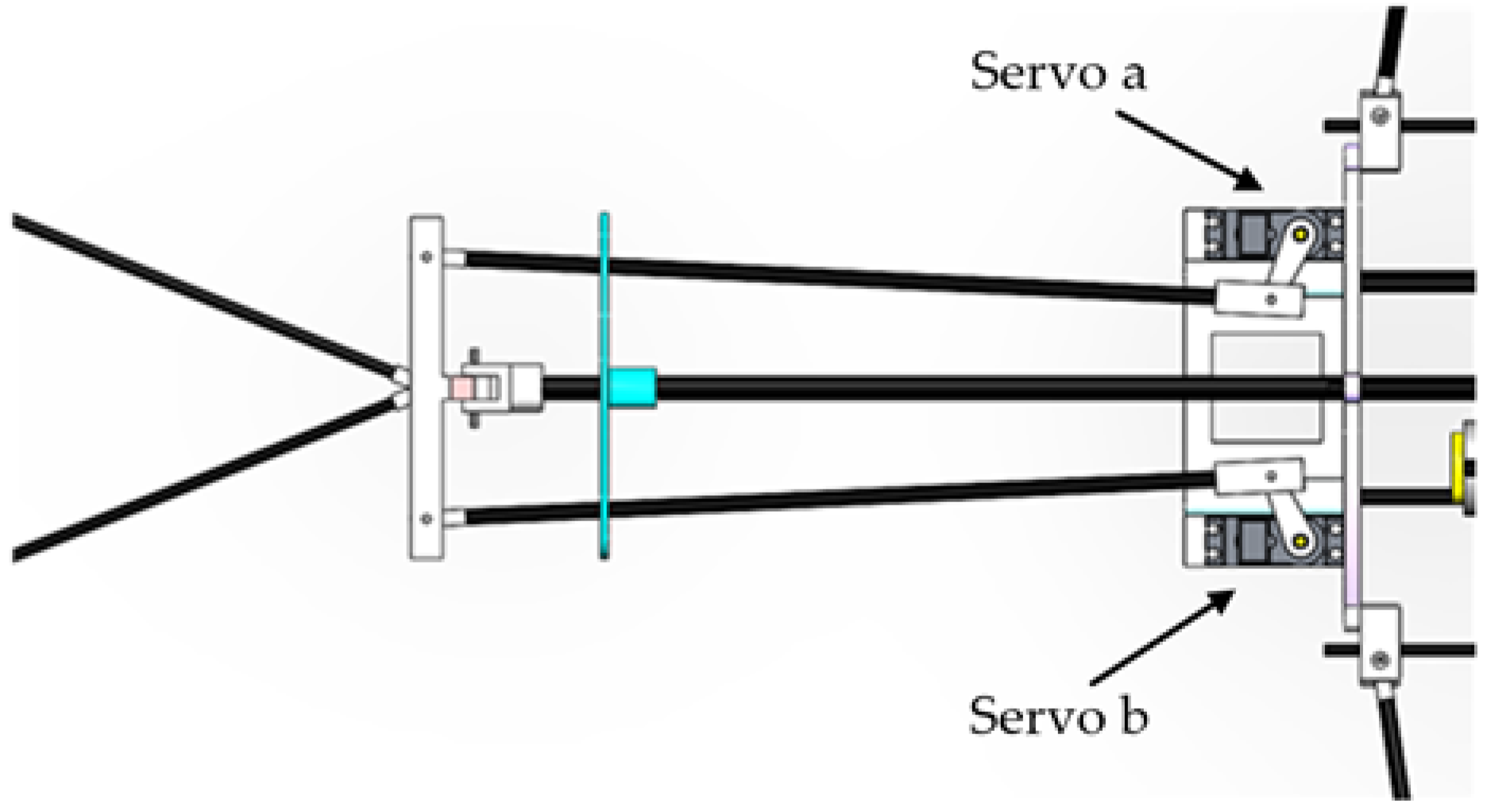
Figure 7.
Changes in the three-axis moment with the tail attitude angle of the bat-like ornithopter.
Figure 7.
Changes in the three-axis moment with the tail attitude angle of the bat-like ornithopter.
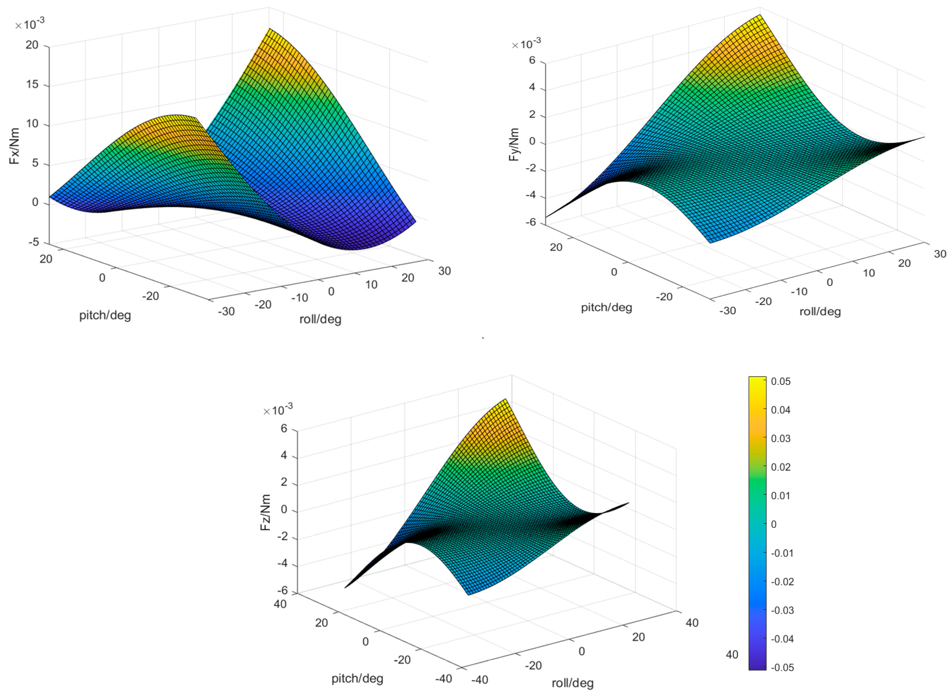
Figure 8.
Influence of the pitch angle on the three-axis moment when is 0.
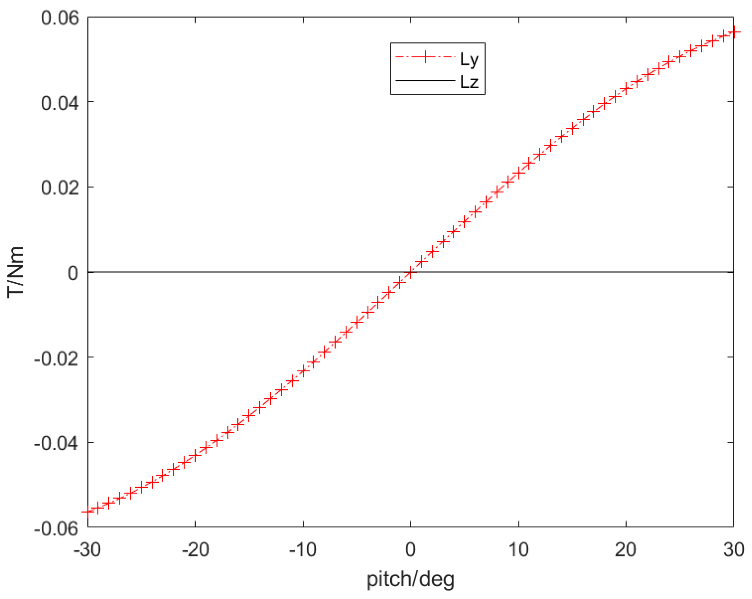
Figure 9.
Bat-like ornithopter prototype.
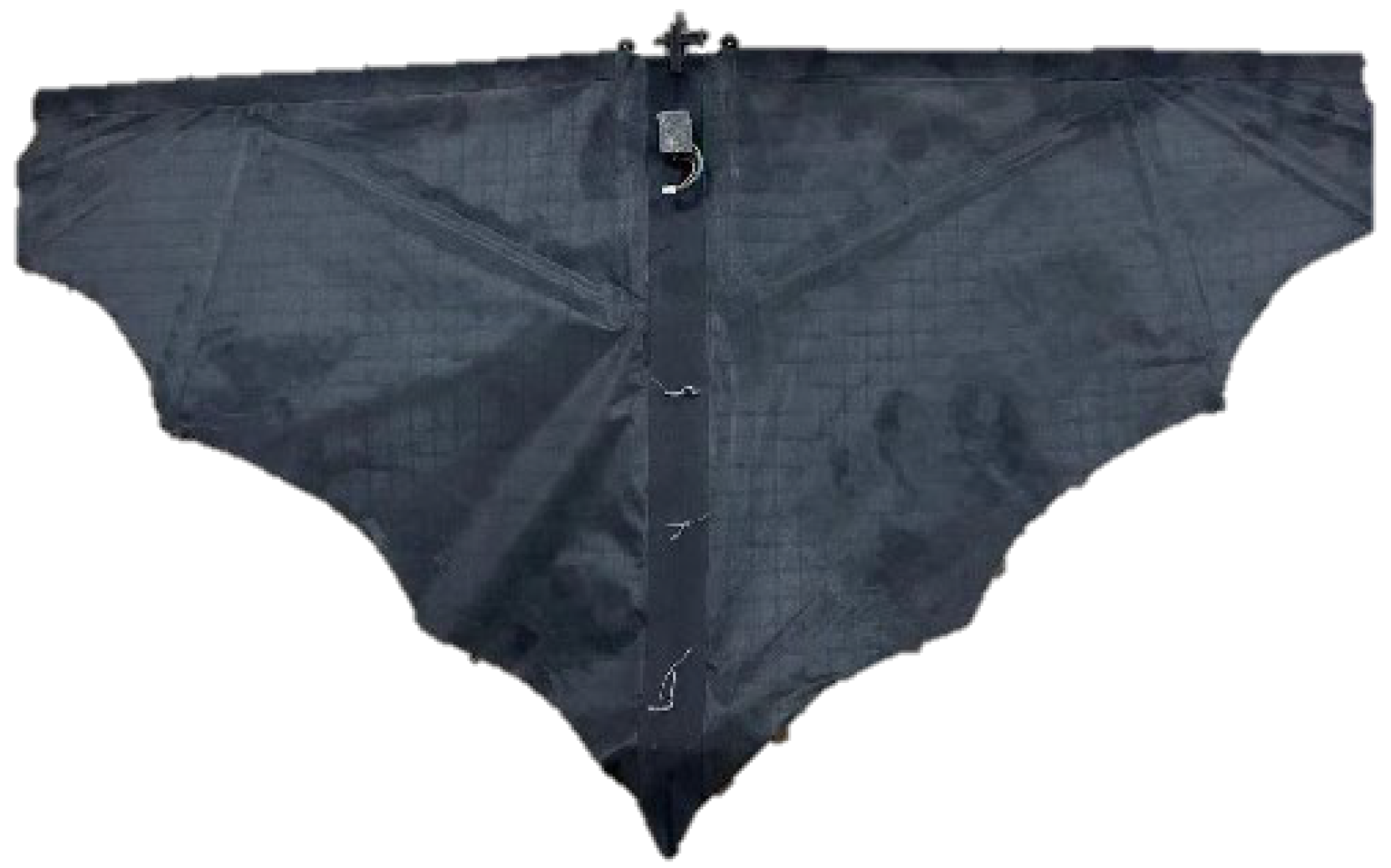
Figure 10.
(a) Changes in the aerodynamic lift force of the rigid swing with . (b) Changes in the aerodynamic resistance of the rigid swing with . (c) Changes in the average aerodynamic lift resistance of a rigid swing with .
Figure 10.
(a) Changes in the aerodynamic lift force of the rigid swing with . (b) Changes in the aerodynamic resistance of the rigid swing with . (c) Changes in the average aerodynamic lift resistance of a rigid swing with .

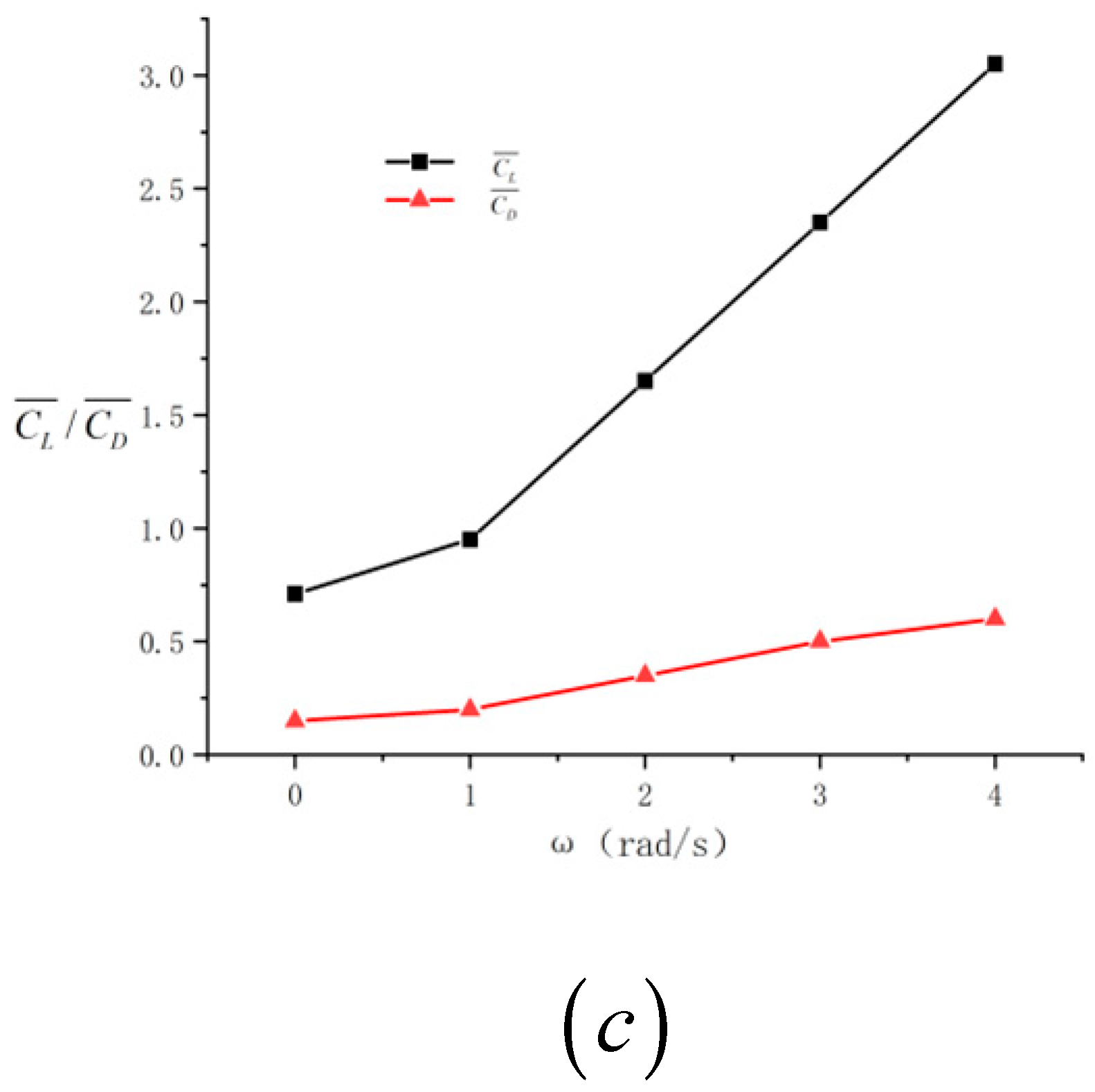
Figure 11.
(a) Changes in of the bat-like ornithopter with . (b) Changes in of the bat-like ornithopter with . (c) Changes in the average lift and drag of the bat-like ornithopter.
Figure 11.
(a) Changes in of the bat-like ornithopter with . (b) Changes in of the bat-like ornithopter with . (c) Changes in the average lift and drag of the bat-like ornithopter.
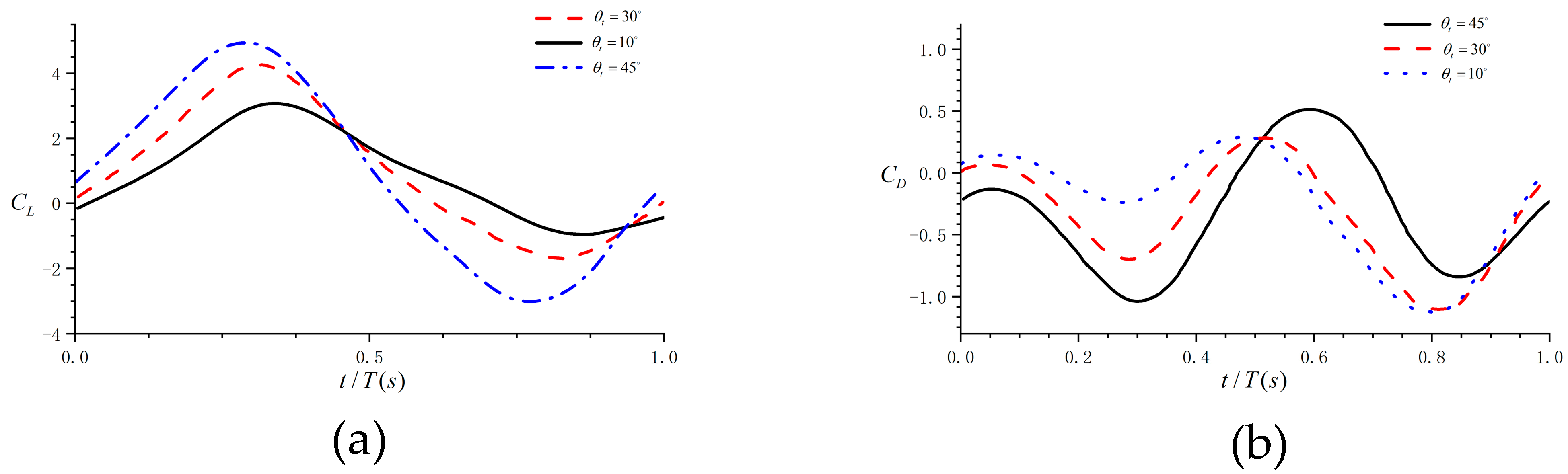
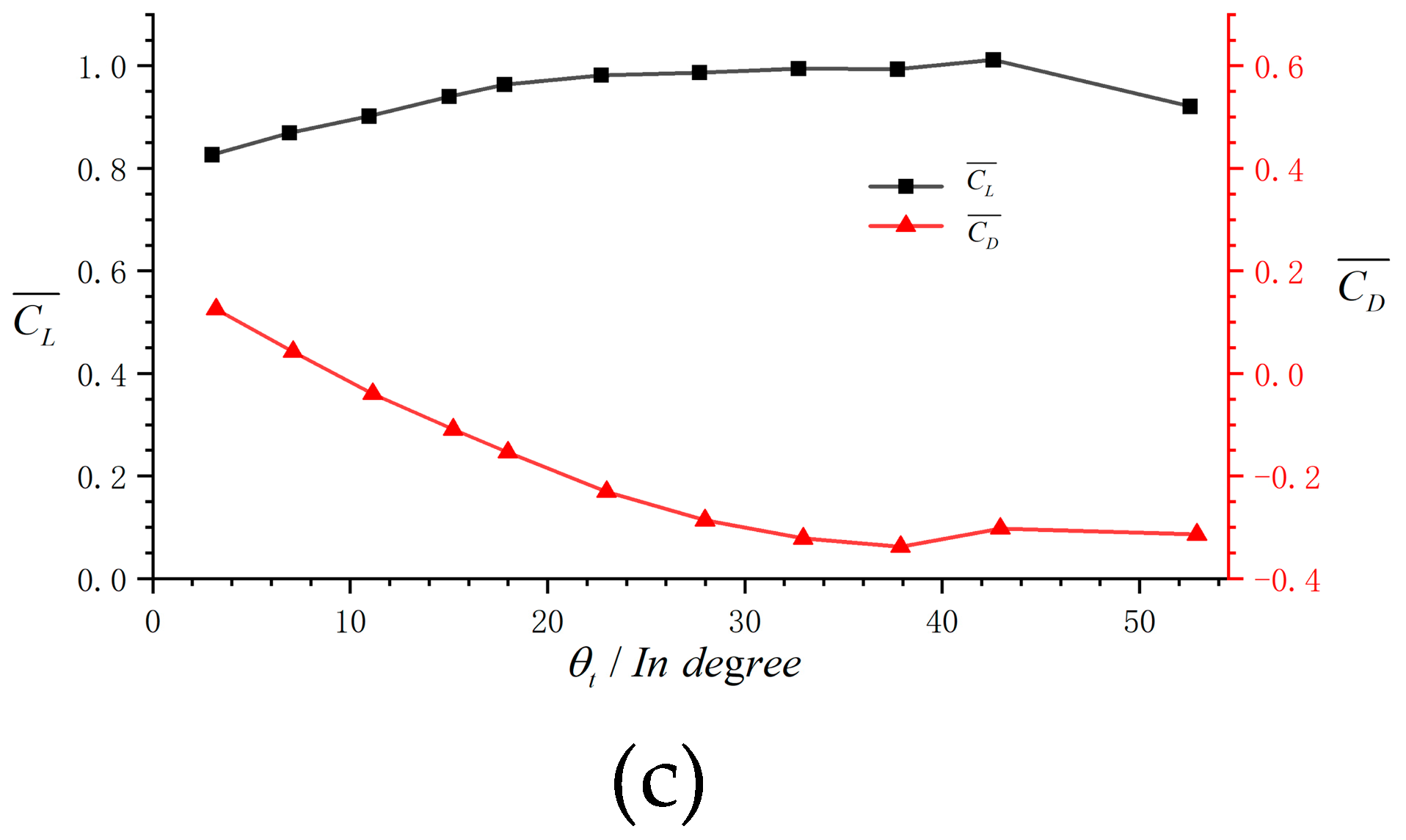
Figure 12.
Open-loop simulation response under angle of attack pulse disturbance.

Figure 13.
Pitch control block diagram of the bat-inspired flapping-wing aircraft based on state feedback.
Figure 13.
Pitch control block diagram of the bat-inspired flapping-wing aircraft based on state feedback.

Figure 14.
LQR-based state feedback control block diagram.
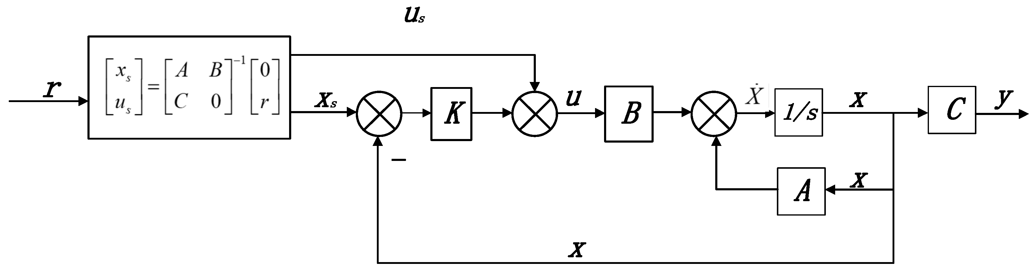
Figure 15.
Zero and pole distribution diagram of the state space equation (x is the pole of the system, o is the zero of the system).
Figure 15.
Zero and pole distribution diagram of the state space equation (x is the pole of the system, o is the zero of the system).
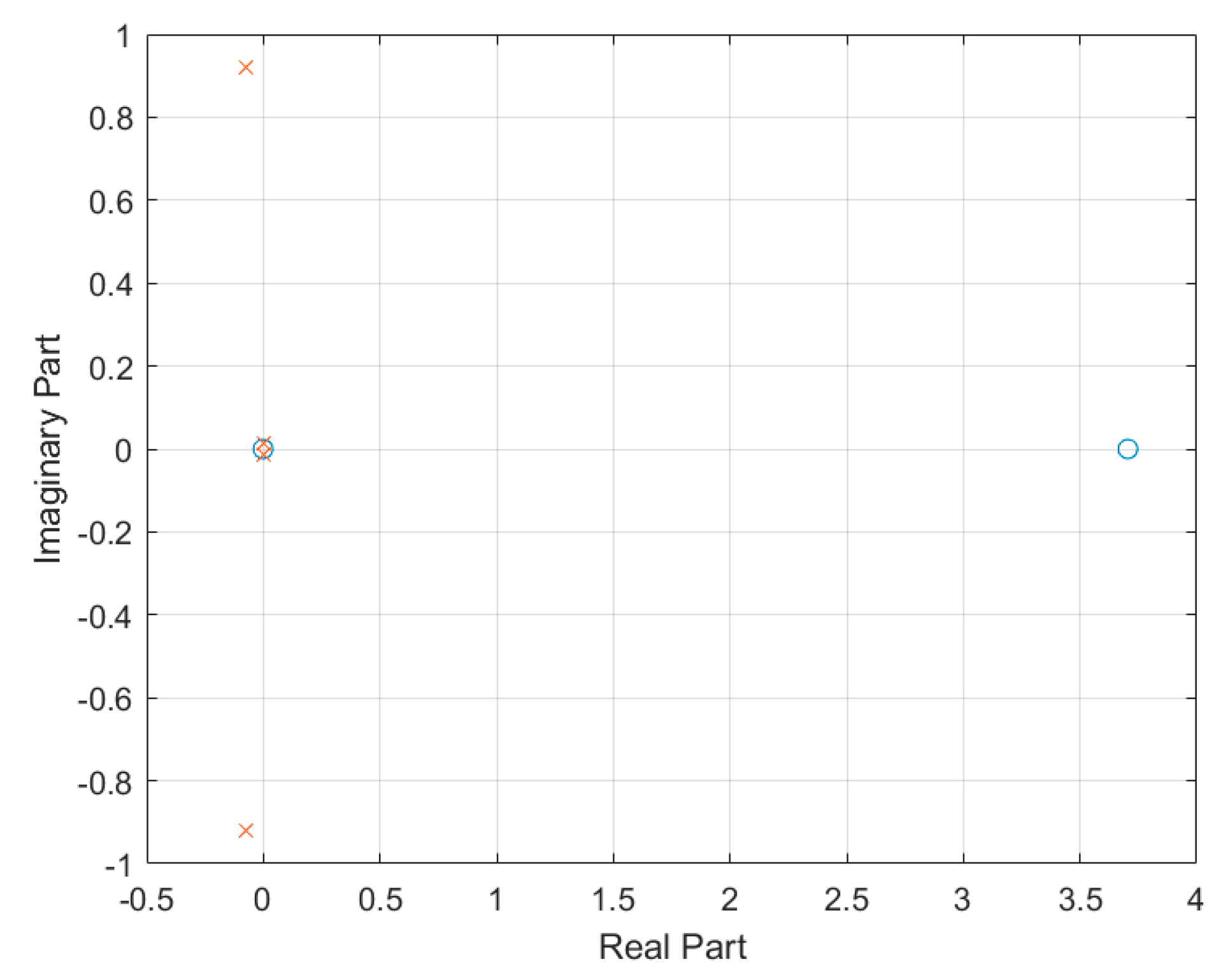
Figure 16.
Pitch angle step response.
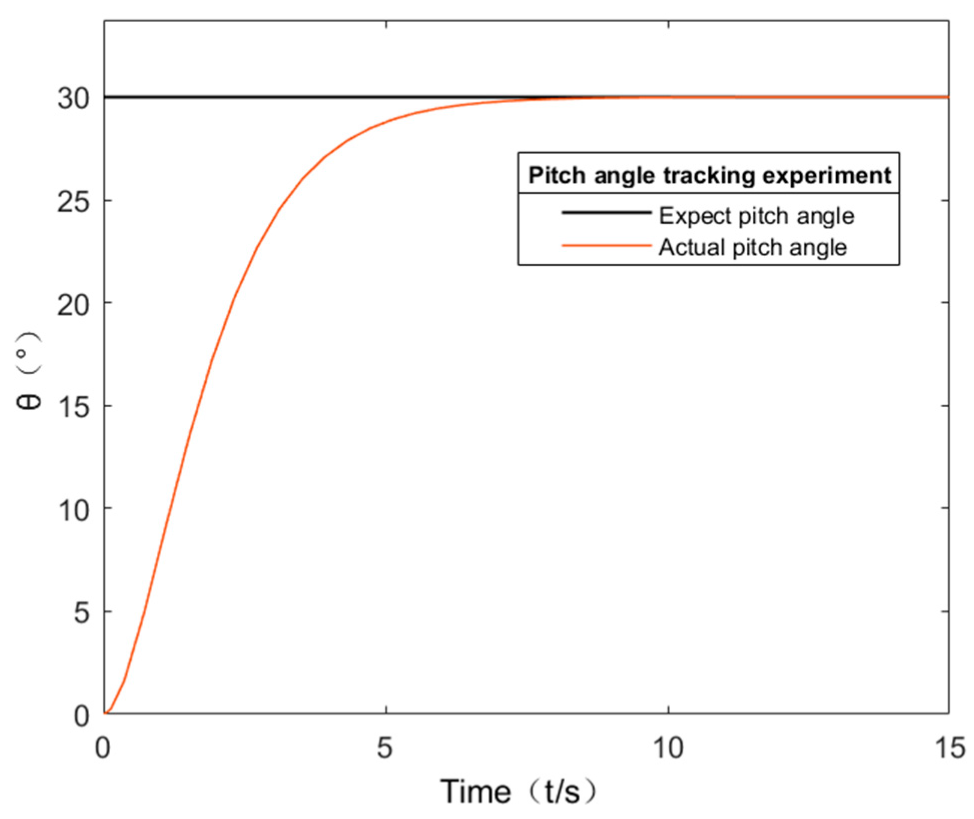
Figure 17.
Pitch angle continuous step response.

Figure 18.
Altitude control response.
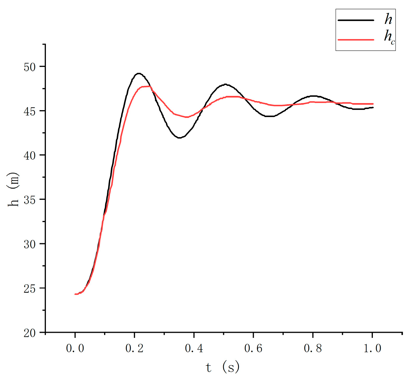
Figure 19.
Bat-like ornithopter drive structure (① is the battery, ② is the brushless motor, and ③ is the double crank and double rocker).
Figure 19.
Bat-like ornithopter drive structure (① is the battery, ② is the brushless motor, and ③ is the double crank and double rocker).
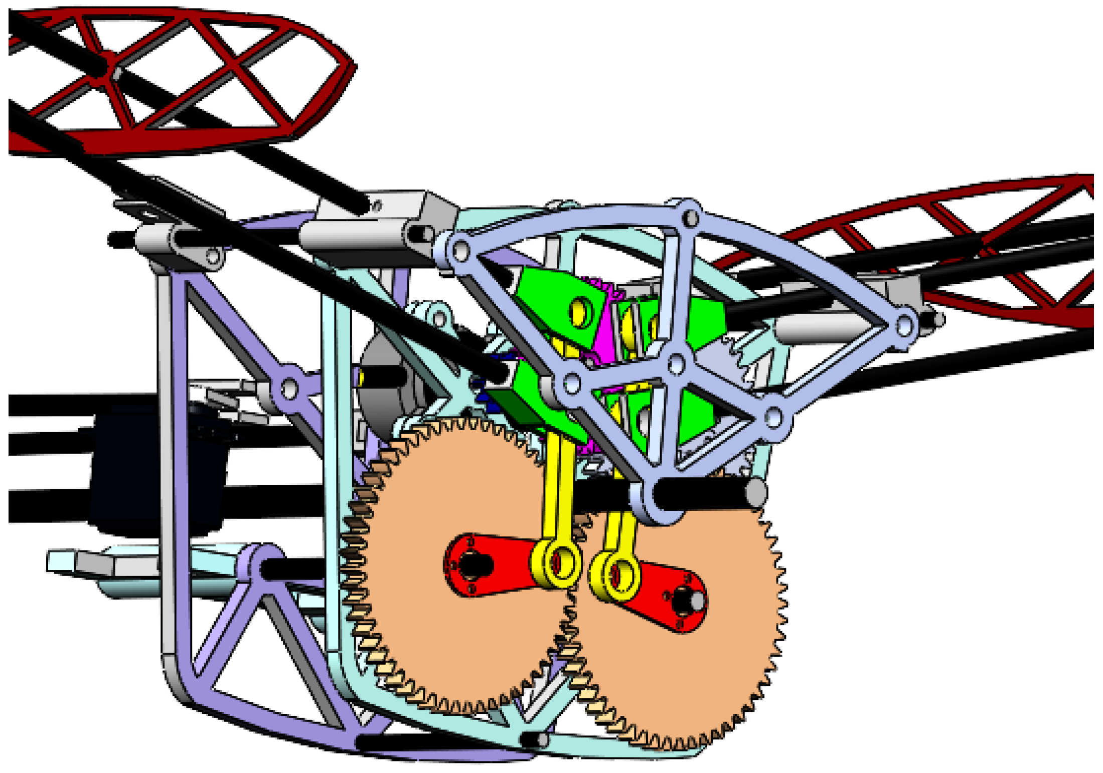
Figure 20.
Flight control and separate inertial navigation module.

Figure 21.
Flight experiment pitch angle tracking situation.

Figure 22.
Flight test. (a) throw away. (b) climb. (c) turn. (d) level flight.

Table 1.
Simulation parameters.
| Parameter Name | Parameter Value |
|---|---|
| Initial flight speed | 5 m/s |
| Initial flight angle of attack | 13° |
| Flapping frequency | 10 Hz |
| Maximum twist angle of trailing edge | ±7° |
| Upshot amplitude | 45° |
| Down shot amplitude | 15° |
Table 2.
Parameters of our prototype of a bat-like ornithopter.
| SP (cm) | C (cm) | AR | |
|---|---|---|---|
| 35 | 4.7 | 7.44 | 13.4 |
Table 3.
Variable Table.
| Variable | Definition | Variable | Definition |
|---|---|---|---|
| T | Thrust | Yaw velocity | |
| Y | Lateral force | Angle of attack | |
| D | Drag | Sideslip angle | |
| L1 | Lift | Roll | |
| p | Pitch velocity | Pitch | |
| q | Roll velocity | Yaw |
Table 4.
Force and moment expressions.
| External Force | ||
| External Moment | ||
Table 5.
Parameters Table.
Disclaimer/Publisher’s Note: The statements, opinions and data contained in all publications are solely those of the individual author(s) and contributor(s) and not of MDPI and/or the editor(s). MDPI and/or the editor(s) disclaim responsibility for any injury to people or property resulting from any ideas, methods, instructions or products referred to in the content. |
© 2024 by the authors. Licensee MDPI, Basel, Switzerland. This article is an open access article distributed under the terms and conditions of the Creative Commons Attribution (CC BY) license (https://creativecommons.org/licenses/by/4.0/).
Share and Cite
MDPI and ACS Style
Wang, F.; Pei, X.; Wu, G.; Bai, Y. Analysis and Design of Bat-Like Flapping-Wing Aircraft. Aerospace 2024, 11, 325. https://doi.org/10.3390/aerospace11040325
AMA Style
Wang F, Pei X, Wu G, Bai Y. Analysis and Design of Bat-Like Flapping-Wing Aircraft. Aerospace. 2024; 11(4):325. https://doi.org/10.3390/aerospace11040325
Chicago/Turabian StyleWang, Fan, Xinbiao Pei, Guangxin Wu, and Yue Bai. 2024. "Analysis and Design of Bat-Like Flapping-Wing Aircraft" Aerospace 11, no. 4: 325. https://doi.org/10.3390/aerospace11040325
Note that from the first issue of 2016, this journal uses article numbers instead of page numbers. See further details here.