
Numerical Investigations on the Effects of Dome Cooling Air Flow on Combustion Characteristics and Emission Behavior in a Can-Type Gas Turbine Combustor
 , , ,
, , ,
Abstract
:1. Introduction
2. Numerical Modeling
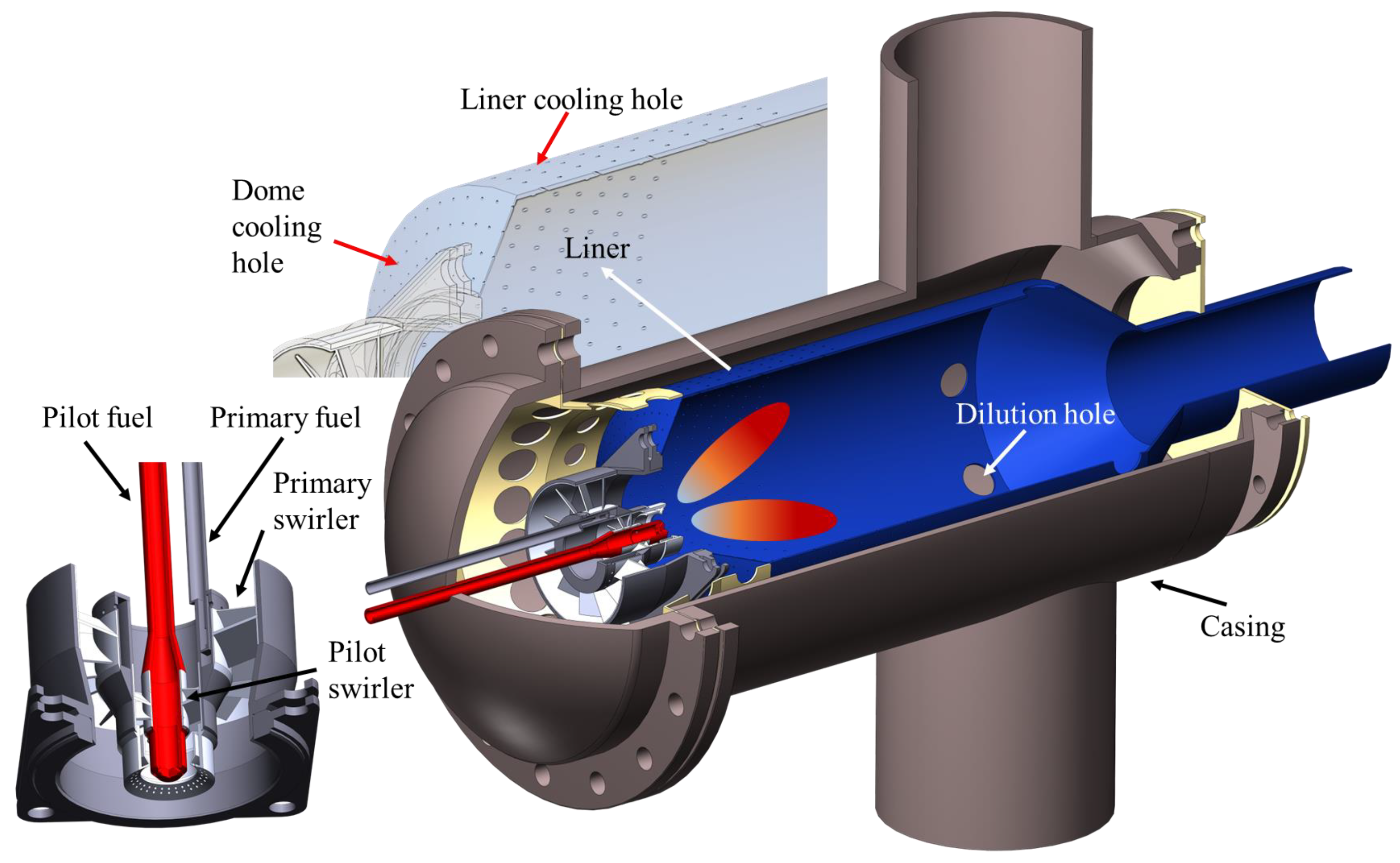
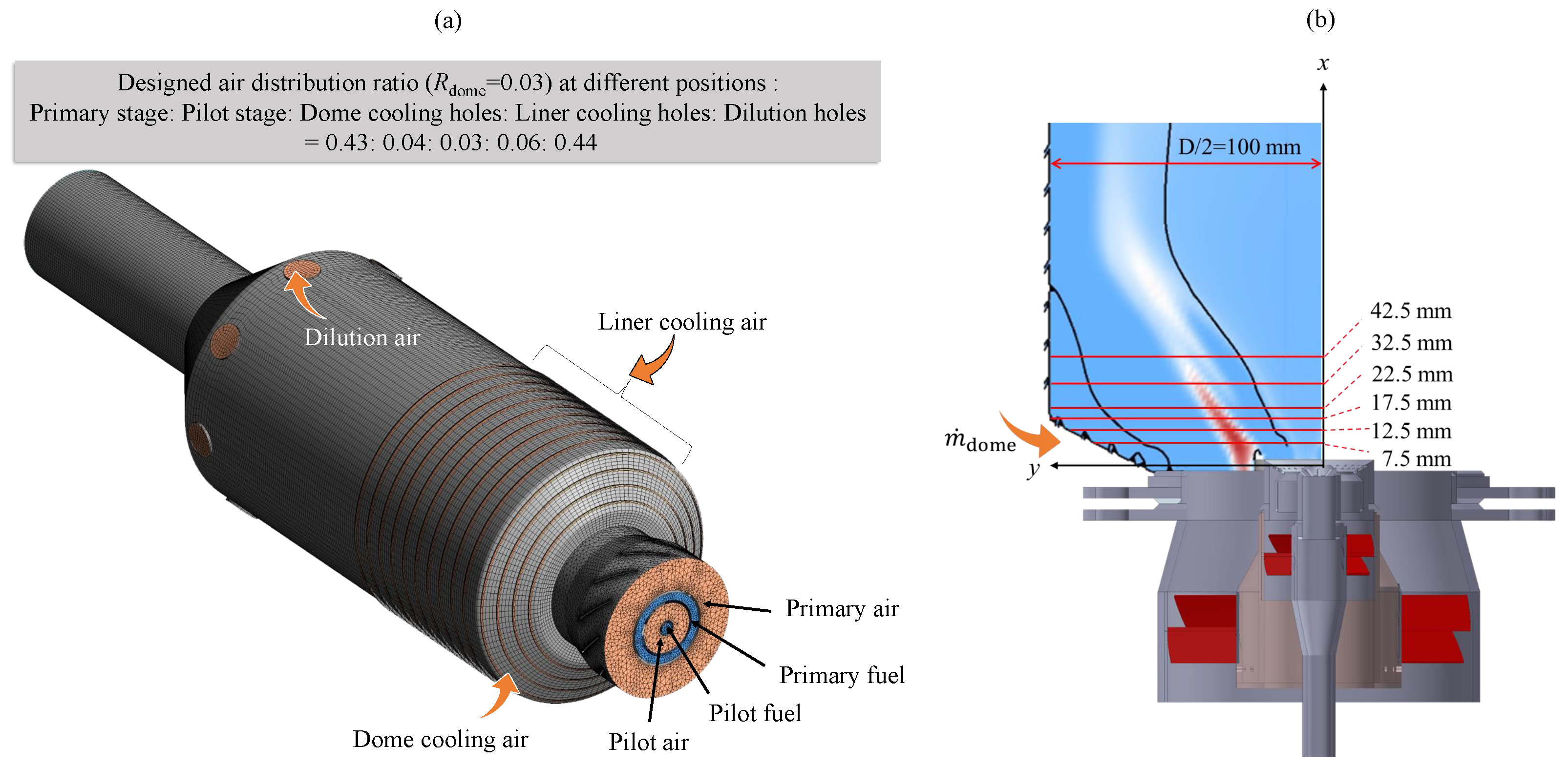
2.1. Configuration of Combustor
2.2. Governing Equations
2.3. Mesh Generation and Independence Study
2.4. Setup of the Simulation Cases
3. Results and Discussion
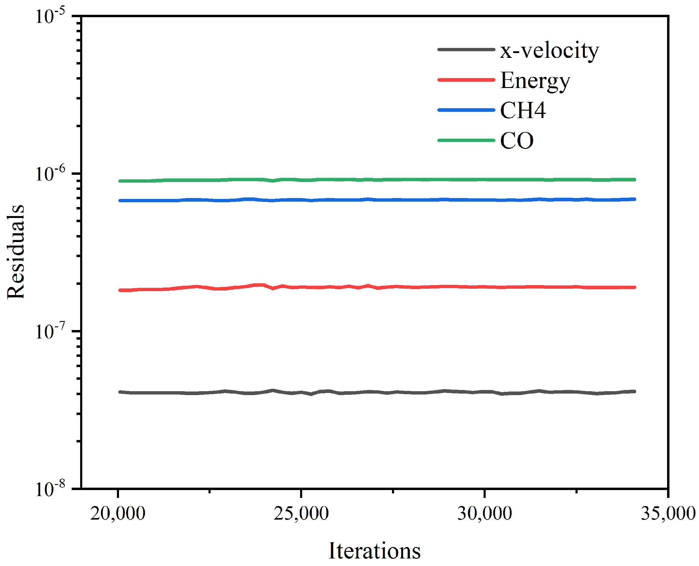
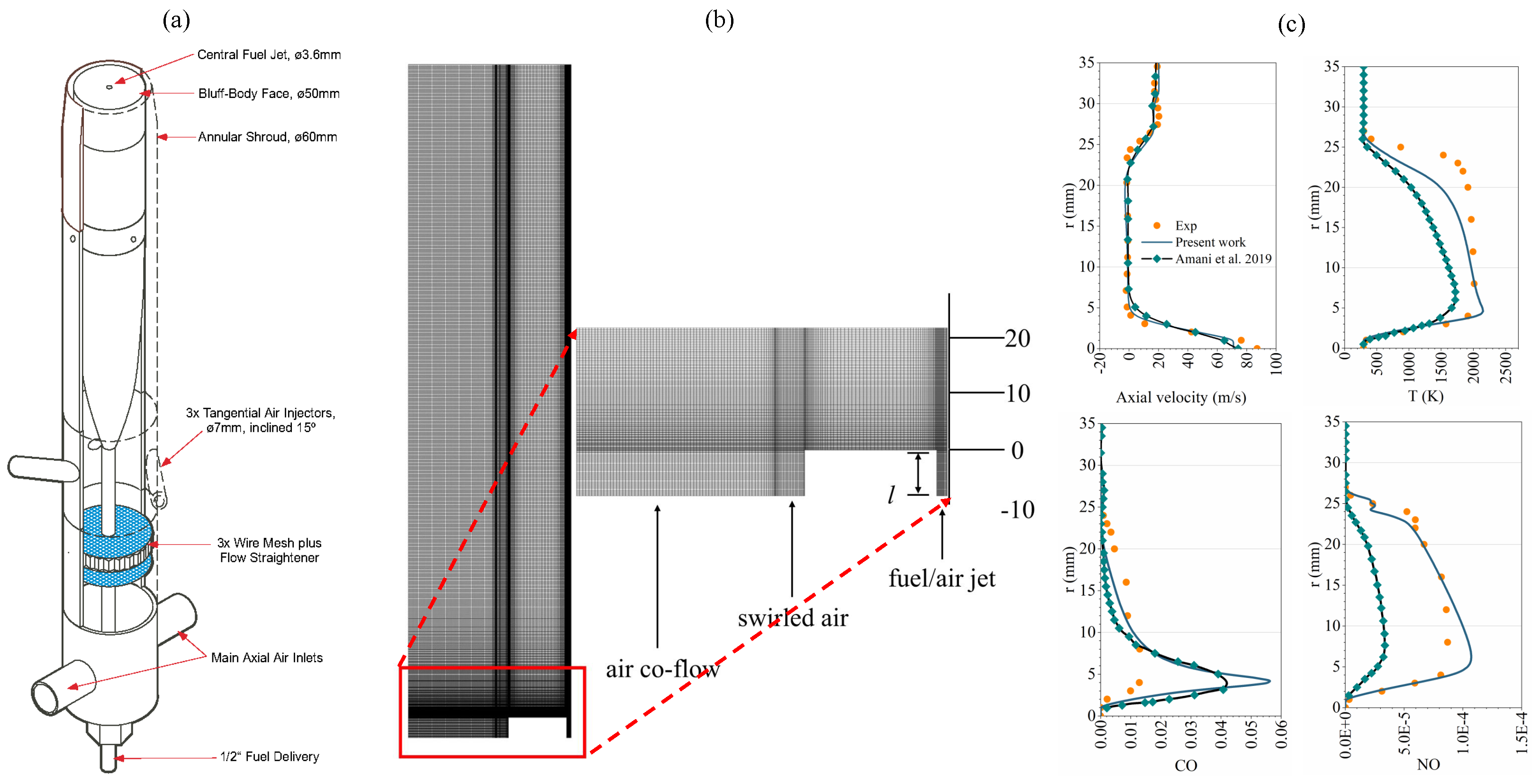
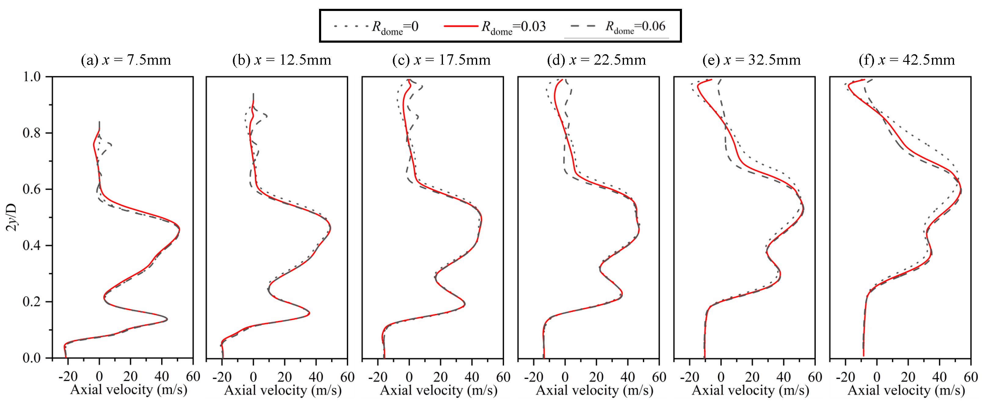
3.1. Validation of the Numerical Model
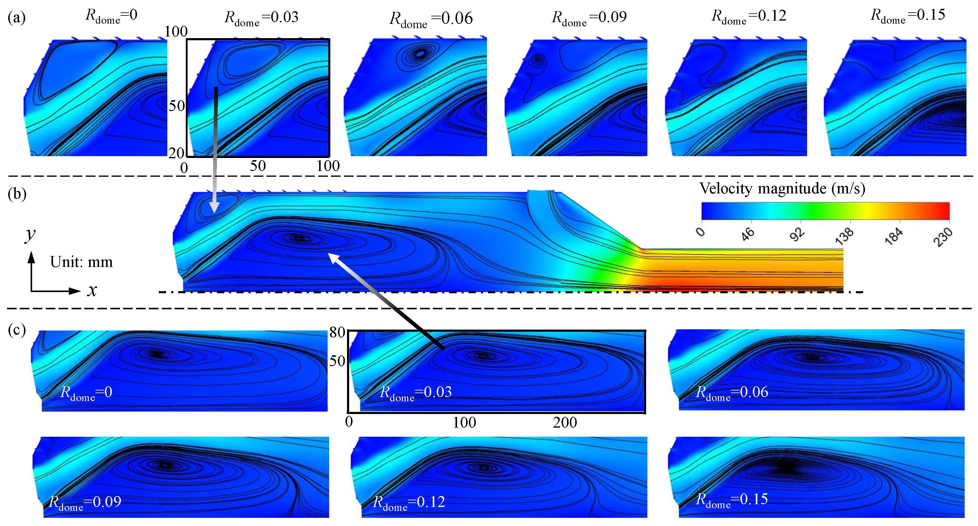
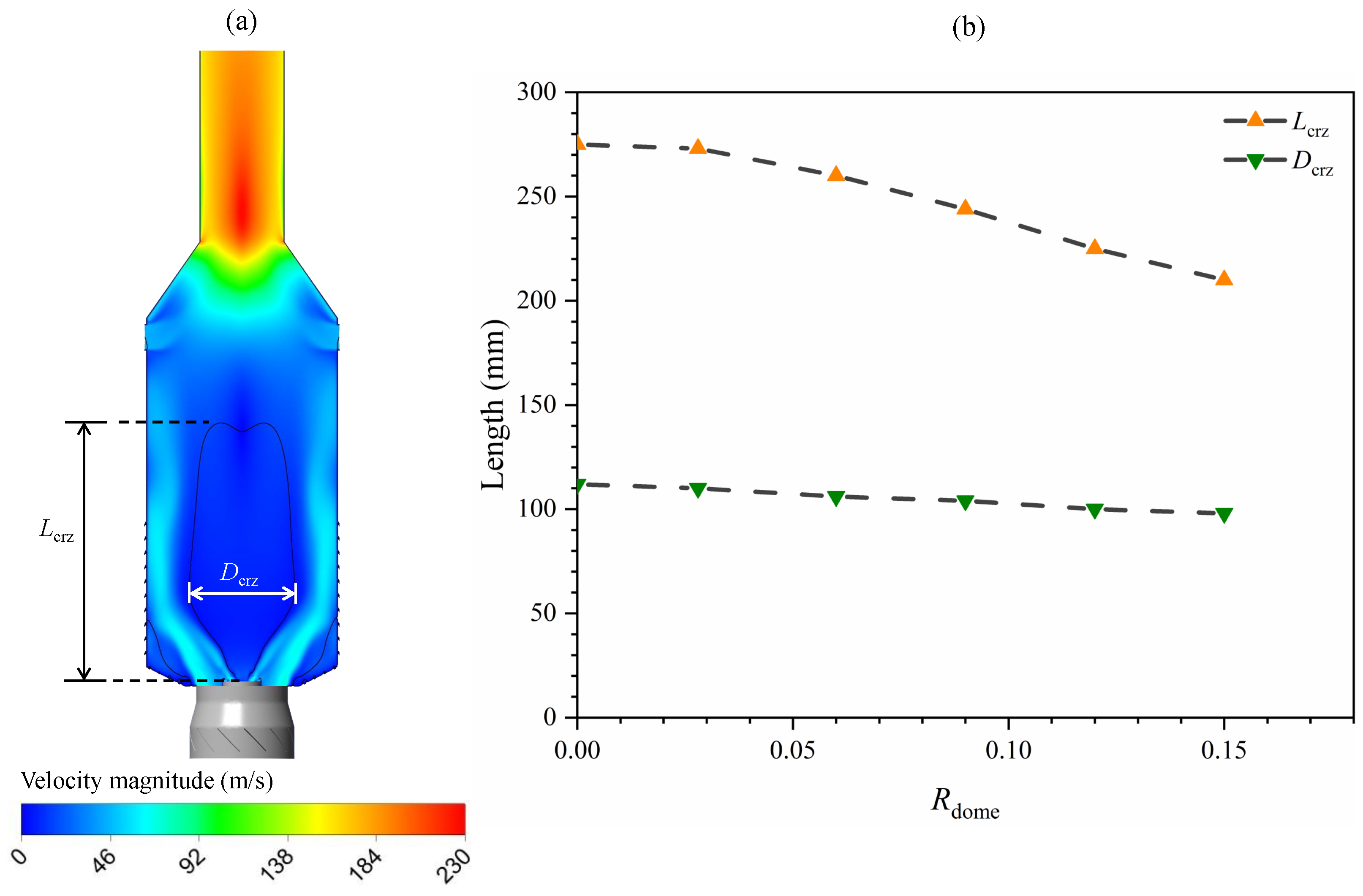
3.2. Effects of the on Flow Fields within the Combustor
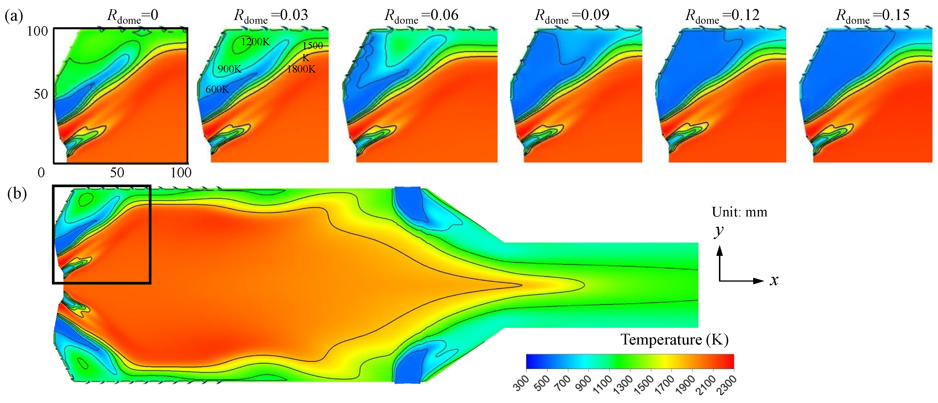
3.3. Effects of the on Temperature and Reaction Rate Distributions
3.4. Effects of the on the NOx Emission Behavior
4. Conclusions
Author Contributions
Funding
Data Availability Statement
Conflicts of Interest
Abbreviations
| CFD | computational fluid dynamics |
| CNG | compressed natural gas |
| CRZ | central recirculation zone |
| EDC | eddy dissipation concept |
| ORZ | outer recirculation zone |
| PIV | particle image velocimetry |
| RANS | Reynolds-averaged Navier-Stokes |
| SMA2 | swirling methane/air flame 2 |
References
- Liu, Y.; Sun, X.; Sethi, V.; Nalianda, D.; Li, Y.G.; Wang, L. Review of modern low emissions combustion technologies for aero gas turbine engines. Prog. Aerosp. Sci. 2017, 94, 12–45. [Google Scholar] [CrossRef]
- Zeldovich, Y.B.; Barenblatt, G.I.; Librovich, V.B.; Makhviladze, G.M. The Mathematical Theory of Combustion and Explosions; Consultants Bureau: New York, NY, USA, 1985. [Google Scholar]
- Siriganano, W.; Merzhabov, A.; De Luca, L. Advances in Combustion Science In Honor of Ya. B. Zelovich. Prog. Astronaut. Aeronaut. 1996, 173. [Google Scholar] [CrossRef]
- Le, X.T.; Nguyen, D.A.; Dinh, C.T. Effect of Two-Head Flared Hole on Film Cooling Performance over a Flat Plate. Aerospace 2021, 8, 128. [Google Scholar] [CrossRef]
- Somarathne, K.; Okafor, E.C.; Hayakawa, A. Emission characteristics of turbulent non-premixed ammonia/air and methane/air swirl flames through a rich-lean combustor under various wall thermal boundary conditions at high pressure. Combust. Flame 2019, 210, 247–261. [Google Scholar] [CrossRef]
- Rivera, J.E.; Gordon, R.L.; Brouzet, D.; Talei, M. Exhaust CO emissions of a laminar premixed propane–air flame interacting with cold gas jets. Combust. Flame 2019, 210, 374–388. [Google Scholar] [CrossRef]
- Huang, Y.; Feng, X.; Lin, Z.; You, Y. Effects of wall cooling with microchannels on swirl combustor performance. Aerosp. Sci. Technol. 2020, 106, 106160. [Google Scholar] [CrossRef]
- Ren, J.; Li, X.; Jiang, H. Conjugate heat transfer characteristics in a highly thermally loaded film cooling configuration with TBC in syngas. Aerospace 2019, 6, 16. [Google Scholar] [CrossRef]
- Tarchi, L.; Facchini, B.; Maiuolo, F.; Coutandin, D. Experimental investigation on the effects of a large recirculating area on the performance of an effusion cooled combustor liner. J. Eng. Gas Turbines Power 2012, 134, 041505. [Google Scholar] [CrossRef]
- Krewinkel, R. A review of gas turbine effusion cooling studies. Int. J. Heat Mass Transf. 2013, 66, 706–722. [Google Scholar] [CrossRef]
- Shen, Z.; Hu, B.; Li, G.; Zhang, H. Large Eddy Simulation of Pulsed Film Cooling with a Dielectric Barrier Discharge Plasma Actuator. Aerospace 2023, 11, 28. [Google Scholar] [CrossRef]
- Mazzei, L.; Puggelli, S.; Bertini, D. Numerical and Experimental Investigation on an Effusion-Cooled Lean Burn Aeronautical Combustor: Aerothermal Field and Emissions. J. Eng. Gas Turbines Power 2019, 141, 041006. [Google Scholar] [CrossRef]
- Ji, Y.; Ge, B.; Zang, S. Analysis of effusion cooling under realistic swirl reacting flow in gas turbine combustor. Appl. Therm. Eng. 2022, 216, 119101. [Google Scholar] [CrossRef]
- Yang, X.; He, Z.; Qiu, P. Numerical investigations on combustion and emission characteristics of a novel elliptical jet-stabilized model combustor. Energy 2019, 170, 1082–1097. [Google Scholar] [CrossRef]
- Yang, G.; Shao, W.; Zhang, Z. Experimental and numerical study on heat transfer characteristics of tangential effusion cooling for a combustor liner. Appl. Therm. Eng. 2022, 218, 119374. [Google Scholar] [CrossRef]
- Ahmed, S.; Ramakrishnan, K.R.; Ekkad, S.V. Overall cooling effectiveness of effusion cooled can combustor liner under reacting and non-reacting conditions. J. Therm. Sci. Eng. Appl. 2022, 14, 021009. [Google Scholar] [CrossRef]
- Hermann, J.; Greifenstein, M.; Boehm, B.; Dreizler, A. Experimental investigation of global combustion characteristics in an effusion cooled single sector model gas turbine combustor. Flow Turbul. Combust. 2019, 102, 1025–1052. [Google Scholar] [CrossRef]
- Wurm, B.; Schulz, A.; Bauer, H.J.; Gerendas, M. Impact of swirl flow on the cooling performance of an effusion cooled combustor liner. J. Eng. Gas Turbines Power 2012, 134, 121503. [Google Scholar] [CrossRef]
- Zong, C.; Ji, C.; Cheng, J.; Zhu, T. Comparison of adiabatic and conjugate heat transfer models on near-wall region flows and thermal characteristics of angled effusion cooling holes. Therm. Sci. Eng. Prog. 2022, 30, 101269. [Google Scholar] [CrossRef]
- Zong, C.; Ji, C.; Cheng, J. Toward off-design loads: Investigations on combustion and emissions characteristics of a micro gas turbine combustor by external combustion-air adjustments. Energy 2022, 253, 124194. [Google Scholar] [CrossRef]
- Zhang, Y.; Li, J.; Xie, J. Effects of lateral cooling hole configuration on a swirl-stabilized combustor. Energy 2022, 259, 125002. [Google Scholar] [CrossRef]
- Lörstad, D.; Lindholm, A.; Pettersson, J. Siemens SGT-800 industrial gas turbine enhanced to 50MW: Combustor design modifications, validation and operation experience. In Turbo Expo: Power for Land, Sea, and Air, Proceedings of the ASME Turbo Expo 2013: Turbine Technical Conference and Exposition, San Antonio, TX, USA, 3–7 June 2013; American Society of Mechanical Engineers: New York, NY, USA, 2013; Volume 55119, V01BT04A038. [Google Scholar] [CrossRef]
- Lörstad, D.; Pettersson, J.; Lindholm, A. Emission reduction and cooling improvements due to the introduction of passive acoustic damping in an existing SGT-800 combustor. In Turbo Expo: Power for Land, Sea, and Air, Proceedings of the ASME Turbo Expo 2009: Power for Land, Sea, and Air, Orlando, FL, USA, 8–12 June 2009; American Society of Mechanical Engineers: New York, NY, USA, 2009; Volume 48845, pp. 1355–1362. [Google Scholar] [CrossRef]
- Greifenstein, M.; Hermann, J.; Boehm, B.; Dreizler, A. Flame–cooling air interaction in an effusion-cooled model gas turbine combustor at elevated pressure. Exp. Fluids 2019, 60, 1–13. [Google Scholar] [CrossRef]
- Greifenstein, M.; Dreizler, A. Investigation of mixing processes of effusion cooling air and main flow in a single sector model gas turbine combustor at elevated pressure. Int. J. Heat Fluid Flow 2021, 88, 108768. [Google Scholar] [CrossRef]
- Wang, Z.; Hu, B.; Fang, A. Analyzing lean blow-off limits of gas turbine combustors based on local and global Damköhler number of reaction zone. Aerosp. Sci. Technol. 2021, 111, 106532. [Google Scholar] [CrossRef]
- Fordoei, E.E.; Mazaheri, K.; Mohammadpour, A. Effects of hydrogen addition to methane on the thermal and ignition delay characteristics of fuel-air, oxygen-enriched and oxy-fuel MILD combustion. Int. J. Hydrogen Energy 2021, 46, 34002–34017. [Google Scholar] [CrossRef]
- ANSYS, Inc. ANSYS Fluent Theory Guide. 2020. Available online: http://www.ansys.com (accessed on 17 April 2024).
- Gregory, P.S.; David, M.G.; Michael, F. GRI-Mech 3.0 Mechanism. 1999. Available online: http://combustion.berkeley.edu/gri-mech/version30/text30.html (accessed on 17 April 2024).
- Kanoshima, R.; Hayakawa, A.; Kudo, T. Effects of initial mixture temperature and pressure on laminar burning velocity and Markstein length of ammonia/air premixed laminar flames. Fuel 2022, 310, 122149. [Google Scholar] [CrossRef]
- Bowman, C.T.; Hanson, R.K.; Davidson, D.F. GRI-Mech 2.11 Mechanism. 1995. Available online: http://combustion.berkeley.edu/gri-mech/new21/version21/text21.html (accessed on 17 April 2024).
- Smooke, M.D. Reduced Kinetic Mechanisms and Asymptotic Approximations for Methane-Air Flames: A Topical Volume; Springer: Berlin/Heidelberg, Germany, 1991. [Google Scholar]
- Tyliszczak, A.; Boguslawski, A.; Nowak, D. Numerical simulations of combustion process in a gas turbine with a single and multi-point fuel injection system. Appl. Energy 2016, 174, 153–165. [Google Scholar] [CrossRef]
- Zhu, R.; Pan, D.; Ji, C. Combustion instability analysis on a partially premixed swirl combustor by thermoacoustic experiments and modeling. Energy 2022, 211, 118884. [Google Scholar] [CrossRef]
- Correa, S.M. A review of NOx formation under gas-turbine combustion conditions. Combust. Sci. Technol. 1993, 87, 329–362. [Google Scholar] [CrossRef]
- Xing, C.; Chen, X.; Qiu, P. Effect of fuel flexibility on combustion performance of a micro-mixing gas turbine combustor at different fuel temperatures. J. Energy Inst. 2022, 102, 100–117. [Google Scholar] [CrossRef]
- Hanson, R.K.; Salimian, S. Survey of rate constants in the N/H/O system. Combust. Chem. 1984, 361–421. [Google Scholar] [CrossRef]
- Masri, A.R.; Kalt, P.A.M.; Barlow, R.S. The compositional structure of swirl-stabilized turbulent nonpremixed flames. Combust. Flame 2004, 137, 1–37. [Google Scholar] [CrossRef]
- Al-Abdeli, Y.M.; Masri, A.R. Stability characteristics and flowfields of turbulent non-premixed swirling flames. Combust. Theory Model. 2003, 7, 731–766. [Google Scholar] [CrossRef]
- Amani, E.; Rahdan, P.; Pourvosoughi, S. Multi-objective optimizations of air partitioning in a gas turbine combustor. Appl. Therm. Eng. 2019, 148, 1292–1302. [Google Scholar] [CrossRef]


| Proportion of Air Flow through Each Part | Case 1 | Case 2 | Case 3 | Case 4 | Case 5 | Case 6 |
|---|---|---|---|---|---|---|
| primary swirler | 0.43 | 0.43 | 0.43 | 0.43 | 0.43 | 0.43 |
| pilot swirler | 0.04 | 0.04 | 0.04 | 0.04 | 0.04 | 0.04 |
| dome cooling holes | 0 | 0.03 | 0.06 | 0.09 | 0.12 | 0.15 |
| liner cooling holes | 0.065 | 0.065 | 0.065 | 0.065 | 0.065 | 0.065 |
| dilution holes | 0.465 | 0.435 | 0.405 | 0.375 | 0.345 | 0.315 |
Disclaimer/Publisher’s Note: The statements, opinions and data contained in all publications are solely those of the individual author(s) and contributor(s) and not of MDPI and/or the editor(s). MDPI and/or the editor(s) disclaim responsibility for any injury to people or property resulting from any ideas, methods, instructions or products referred to in the content. |
© 2024 by the authors. Licensee MDPI, Basel, Switzerland. This article is an open access article distributed under the terms and conditions of the Creative Commons Attribution (CC BY) license (https://creativecommons.org/licenses/by/4.0/).
Share and Cite
Ji, C.; Shi, W.; Ke, E.; Cheng, J.; Zhu, T.; Zong, C.; Li, X. Numerical Investigations on the Effects of Dome Cooling Air Flow on Combustion Characteristics and Emission Behavior in a Can-Type Gas Turbine Combustor. Aerospace 2024, 11, 338. https://doi.org/10.3390/aerospace11050338
Ji C, Shi W, Ke E, Cheng J, Zhu T, Zong C, Li X. Numerical Investigations on the Effects of Dome Cooling Air Flow on Combustion Characteristics and Emission Behavior in a Can-Type Gas Turbine Combustor. Aerospace. 2024; 11(5):338. https://doi.org/10.3390/aerospace11050338
Chicago/Turabian StyleJi, Chenzhen, Wentao Shi, Enlei Ke, Jiaying Cheng, Tong Zhu, Chao Zong, and Xinyan Li. 2024. "Numerical Investigations on the Effects of Dome Cooling Air Flow on Combustion Characteristics and Emission Behavior in a Can-Type Gas Turbine Combustor" Aerospace 11, no. 5: 338. https://doi.org/10.3390/aerospace11050338